
CATU7000U - AV amplifier PANASONIC - Free user manual and instructions
Find the device manual for free CATU7000U PANASONIC in PDF.

| Product Type | Audio-video amplifier with receiver |
| Brand | Panasonic |
| Model | CATU7000U |
| Dimensions (W x H x D) | 430 x 160 x 340 mm |
| Weight | Approximately 8 kg |
| Power Supply | 230 V ~ 50 Hz |
| Power Consumption | 400 W (max) |
| Output Power | 5 channels, 100 W per channel (8 ohms) |
| Main Features | Multi-channel amplification, AM/FM radio reception, surround audio decoder, HDMI connectivity |
| Inputs | HDMI, optical, coaxial, RCA, USB |
| Outputs | Speakers (5.1), subwoofer, HDMI (ARC), headphone |
| Supported Audio Formats | Dolby Digital, DTS, PCM, MP3, AAC |
| Maintenance and Cleaning | Unplug the device, clean with a soft dry cloth. Do not use solvents. |
| Safety | Do not expose to moisture, heat sources or vibrations. Use in a well-ventilated area. |
| Spare Parts and Repairability | Contact Panasonic after-sales service for parts and repairs. Repairability index: 7/10 |
| Included Accessories | Remote control, batteries, FM antenna, power cable |
Frequently Asked Questions - CATU7000U PANASONIC
User questions about CATU7000U PANASONIC
0 question about this device. Answer the ones you know or ask your own.
Ask a new question about this device
Download the instructions for your AV amplifier in PDF format for free! Find your manual CATU7000U - PANASONIC and take your electronic device back in hand. On this page are published all the documents necessary for the use of your device. CATU7000U by PANASONIC.
USER MANUAL CATU7000U PANASONIC
AV Control Unit with Receiver
Radio Frequency Interference Statement (Part 15 of the FCC Rules): Applies only in U.S.A.
This equipment has been tested and found to comply with the limits for a Class B digital, pursuant to Part 15 of the FCC Rules.
- These limits are designed to provide reasonable protection against harmful interference in an automobile installation. This equipment generates, uses, and can radiate radio frequency energy and, if not installed and used in accordance with the instructions, may cause harmful interference to radio communications. However, there is no guarantee that interference will not occur in a particular installation. If this equipment does cause harmful interference to radio or television reception, which can be determined by turning the equipment off and on, the user is encouraged to consult the dealer or an experience radio technician for help.
FCC Warning
Any unauthorized changes or modifications to this equipment would void the user's authority to operate this device.
This device complies with Part 15 of the FCC Rules:
Operation is subject to the following two conditions:
(1) This device may not cause harmful inerference, and
(2) This device must accept any interference received, including interference that may cause undesired operation.
For Canada:
This Class B digital apparatus complies with Canadian ICES-003.
WARNING:
TO REDUCE THE RISK OF FIRE OR ELECTRIC SHOCK, DO NOT EXPOSE THIS PRODUCT TO RAIN OR MOISTURE.
TO REDUCE THE RISK OF FIRE OR ELECTRIC SHOCK, AND ANNOYING INTERFERENCE, USE ONLY THE INCLUDED COMPONENTS.
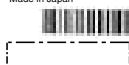
Label Indication and Location
Identification label
Panasonic
Model No. N° De Mo
CA-TU7000U
Manufactured by Matsushita Communication
Industrial Co. Ltd. Yokohama Japan
Made in Japan
m = 311 ;
This device complies with Part 15 of the
FCC Rules. Operation is subject to the
condition that this device does not cause harmful interference.
Find the model number and serial number on either the back or bottom of the unit. Please record them in the space below and retain this booklet as a permanent record of your purchase to help with identification in case of theft.
MODEL NUMBER
CA-TU7000U
SERIAL NUMBER
DATE PURCHASED
FROM
WARNING:
TO AVOID THE RISK OF SERIOUS INJURY OR POSSIBLE VIOLATION OF LAWS, NOT FOR USE WHERE VISIBLE TO DRIVER FOR ANY PURPOSE OTHER THAN NAVIGATION OR USE WITH REAR VIEW CAMERA.
When Driving
- The driver must not operate the color LCD monitor. Operating the color LCD monitor may lead to distraction and cause an accident. Stop your vehicle in a safe location when operating the unit.
- The driver must not watch videos while driving. It may lead to distraction and cause an accident.
- Keep the unit at an appropriate sound level. Driving with the sound at a level that prevents you from hearing sounds outside and around the vehicle may cause an accident.
When Driving
Keep the volume level low enough to be aware of road and traffic conditions.
When Car Washing
Do not expose the product, including the speakers and CDs, to water or excessive moisture. This could cause electrical shorts, fire, or other damage.
When Parked
Parking in direct sunlight can produce very high temperatures inside your vehicle. Give the interior a chance to cool down before switching the unit on.
Use the Proper Power Supply
This product is designed to operate with a 12 volt, negative ground battery system (the normal system in a North American car.)
Disc Mechanism
Do not insert coins or any small objects. Keep screwdrivers and other metallic objects away from the disc mechanism and disc.
Use Authorized Serviccenters
Do not attempt to disassemble or adjust this precision product. Please refer to the Servicenter list included with this product for service assistance.
For Installation
The product should be installed in a horizontal position with the front end up at a convenient angle, but not more than 30^ .
Components
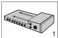
1. AV Control Unit
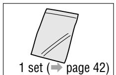
2. Installation Hardware
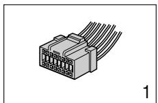
3. Power Connector
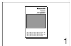
4. Operating Instructions
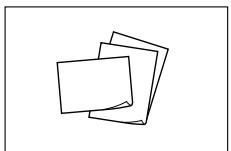
5. Warranty Card,etc.
This system is designed so that you can not see picture from VCR, DVD player, and other devices while you are driving.
- Park your car in a safe place and engage the parking brake before watching the monitor.
- Picture can be seen on the second monitor.
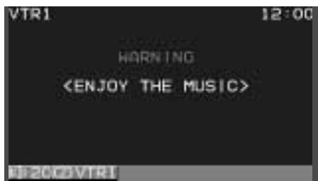
Note: Be sure to connect the parking brake connection lead. ( Operating Instructions for CY-VMC7000U page 46)
Cautions
- Picture might not be displayed, or it might take more time than usual to display picture in low temperature. Also, movement of picture might become labored, or picture quality might become deteriorate as well in low temperature. (practicable temperature: 0^ - 40^ )
- Do not touch the LCD (liquid crystal display). If you touch the LCD, your fingerprints will be conspicuous because the surface of the LCD was specially processed.
- In some cases, noise is generated. It depends on the position or direction of a cellular phone. Change the position or direction of the cellular phone, or keep it away from the unit.
ID Code
Prior to operating this unit, it is a advisable to assign your 4-digit ID code for security. (Make sure to use four digits for ID code. ID code can not be set with two or three digits.)
Once the ID code has been set, the unit cannot be operated if the main power supply is disconnected then re-connected. It is electronically locked so that a thief could not use the stolen unit unless that person knows the code you have set.
The ID code operation must be performed only by the person whom the unit belongs to.
Generally, it is not necessary to enter the ID code each time when using the unit if it has never been disconnected from the main power supply (car battery). For the ID code setting procedures, see pages 34 to 35.
Caution: Record your registered ID code and keep it in a secure location. If you forget it, you will be unable to use the unit. In case that you can not operate the unit because of forgetting the ID code, please consult your nearest Panasonic Servicenter.
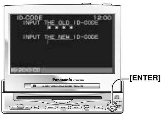
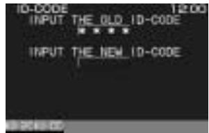
ID Code Input
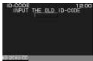
Enter the ID code after turning on the power and activating the display.
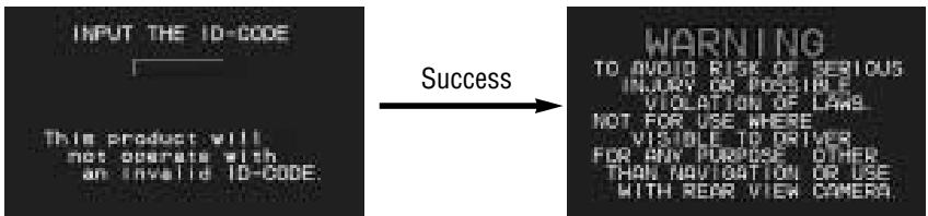
Note: When failing in entering ID code, a screen on the right is displayed, and the unit beeps three times. Enter a correct ID code.
In case of failing in entering ID code three times consecutively, the power is turned off. Turn on the power again and enter a correct ID code in this case.

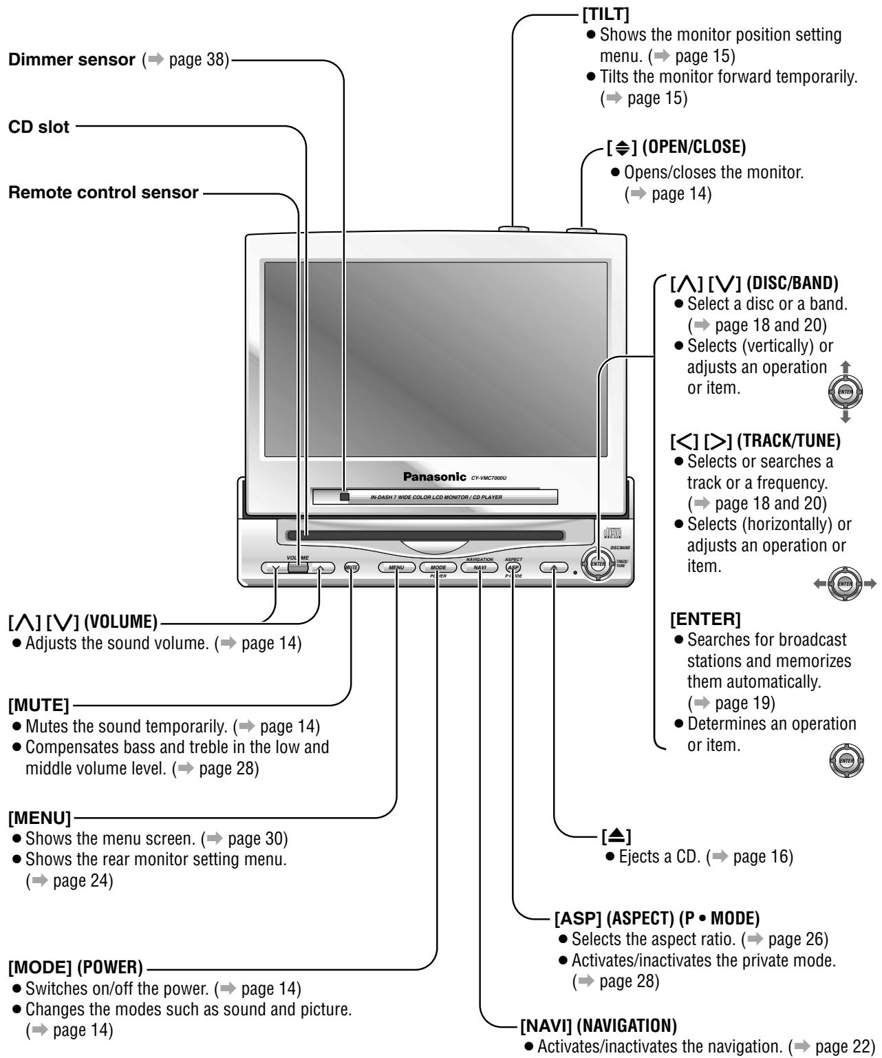
Name of Controls and Functions
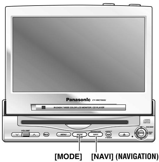
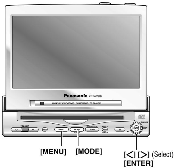
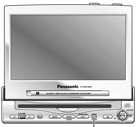
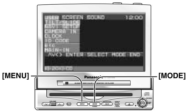
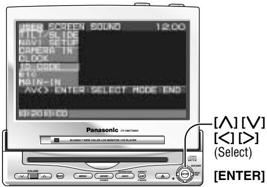
Display Unit (CY-VMC7000U)
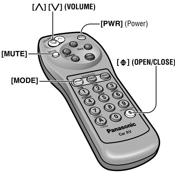
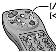
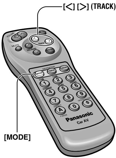
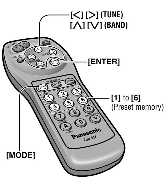
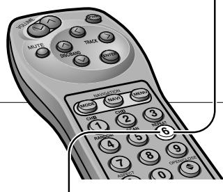
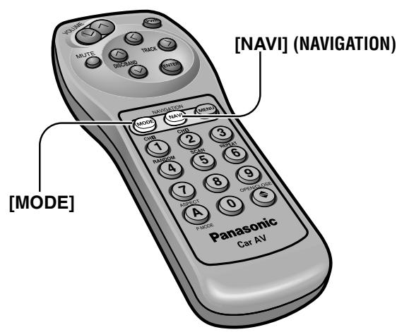
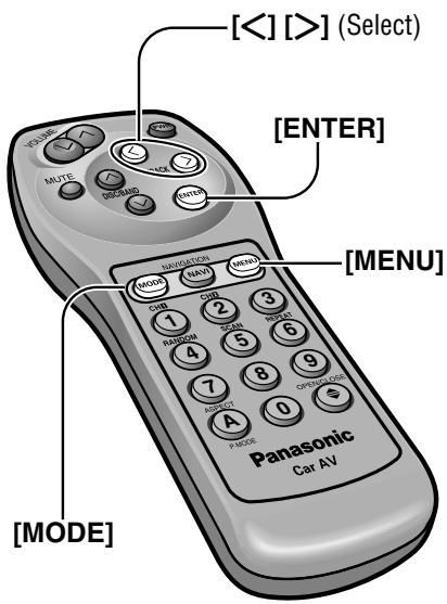
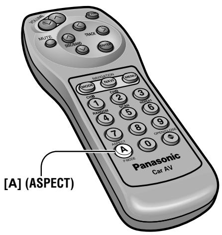
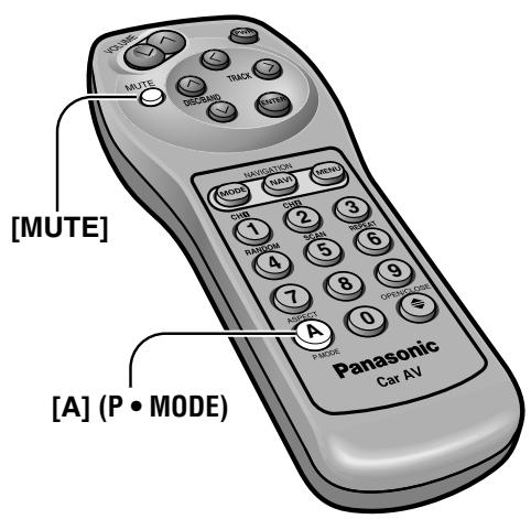
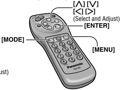
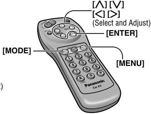
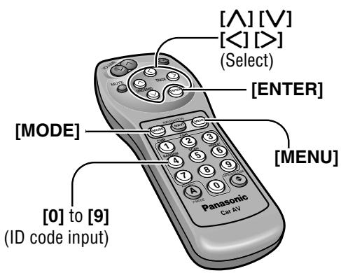
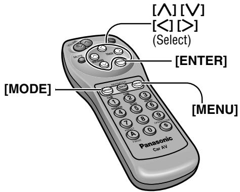
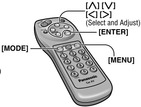
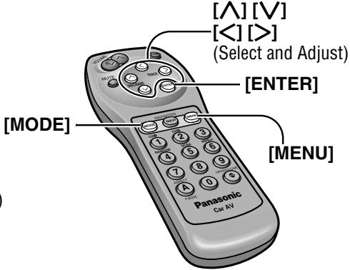
Remote Control (supplied with CY-VMC7000U)
Aim the remote control at the remote control sensor of the display unit and operate it.
[PWR]
- Switches on/off the power. (→ page 14)
[A][V](VOLUME)
- Adjusts the sound volume.
(→ page 14)
[MUTE]
- Mutes the sound temporarily.
(→ page 14)
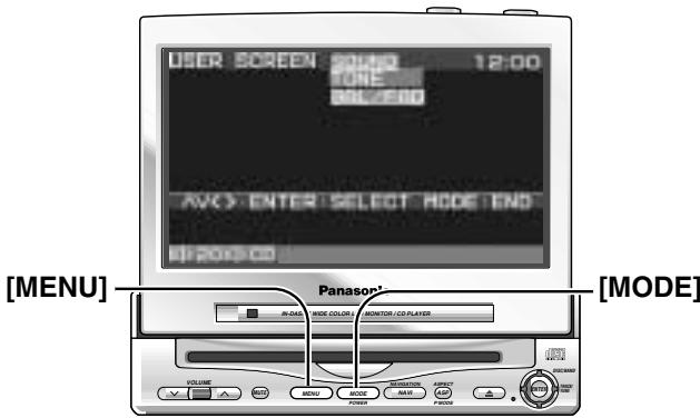
[MODE]
- Switches on/off the power. (→ page 14)
Changes the modes such as sound and picture. ( page 14)
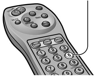
[0] to [9]
- Selects listening pattern. (→ page 17 and 21)
- Sets the ID code. (→ page 34)
- Memorize broadcast stations. (→ page 19)
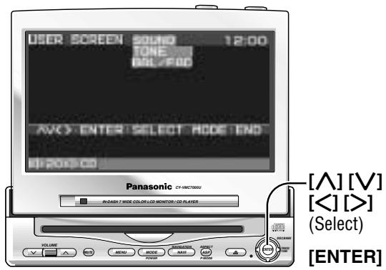
[△][V](DISC/BAND)
- Select a disc or a band. (→ page 18 and 20)
- Selects (vertically) or adjusts an operation or item.
[ [< ] ] [>] (TRACK)
- Selects or searches a track or a frequency.
(→ page 18 and 20) - Selects (horizontally) or adjusts an operation or item.
[ENTER]
- Searches for broadcast stations and memorizes them automatically. (→ page 19)
- Determines an operation or item.
[NAVI] (NAVIGATION)
- Activates/inactivates the navigation.
(→ page 22)
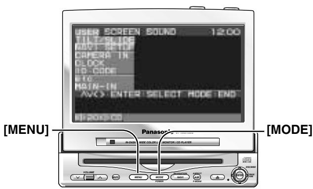
[MENU]
- Shows the menu screen.
(→ page 30) - Shows the rear monitor setting menu. (→ page 24)
[ ] (OPEN/CLOSE)
- Opens/closes the monitor.
(→ page 14)
[A] (ASPECT) (P • MODE)
- Selects the aspect ratio.
(→ page 26) - Activates/inactivates the private mode. ( page 28)
![PANASONIC CATU7000U - [A] (ASPECT) (P • MODE) - 1](/content/2019/11/105079/images/9f8c0432f1d153f2389e9ba9c85093274ab7955c14aeabfffe27261fcc104773.jpg)
Turn the key in the ignition until the accessory indicator lights.
Power
ON: Press [MODE] (POWER). (On the display unit) Press [PWR] or [MODE]. (On the remote control)
OFF: Press [MODE] (POWER) again for more than 2 seconds. (On the display unit) Press [PWR] again or [MODE] again for more than 2 seconds. (On the remote control)
Display Open / Close
OPEN:Press [ ] (OPEN/CLOSE).
If the unit stops halfway, press [ 念 ] (OPEN/CLOSE) again and draw it all the way in.
CLOSE: Press [ ] (OPEN/CLOSE) again.
(After return the lateral angle to the neutral position.)
Note: When the display unit is opened or closed, a loud beep sounds three times.
Warning: Do not insert hands, fingers or foreign objects into the unit while the display is moving. Inserting your hands, fingers or foreign objects into the unit can cause injuries and damage to the unit.
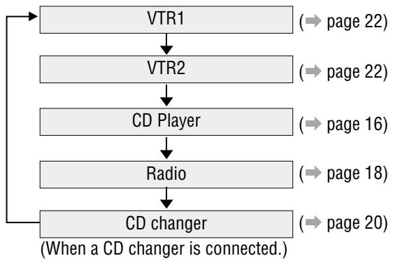
Mode
Press [MODE] to change the mode.
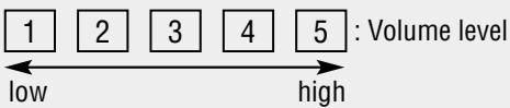
Volume
[Λ] (VOLUME): Up
[√] (VOLUME): Down
VOLUME20
Default:Volume20
Setting Range : 0 to 40
Note: The sound level for each source is stored in memory.
MUTE
MUTE ON: Press [MUTE].
MUTE OFF: Press [MUTE] again.
Monitor Position Adjustment
Cautions:
- For smooth adjustment, make sure to first return the lateral angle to the neutral position and then adjust the tilt angle.
- Do not manually change the position of the unit by using force.
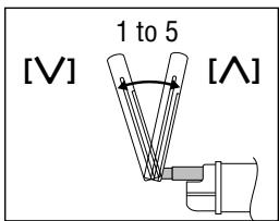
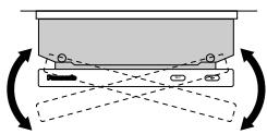
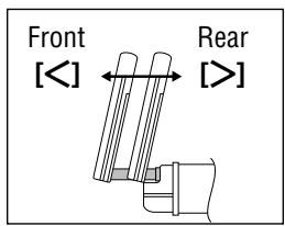
Tilt Angle / Front-Rear Position
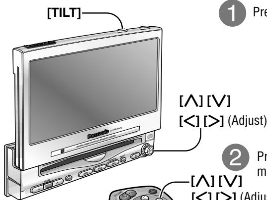
Press and hold [TILT] on the display unit for more than 1 second.
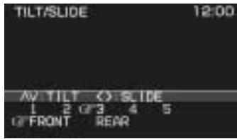
Monitor Position Setting Menu
Press [] or [] to adjust the tilt angle. Press [ ] or [>] to move the display to the front or rear position.
[ʌ][V] mov
[<] [>] (Adjust)
Tilt Angle
Position "REAR" and tilt angle "5" cannot be selected at the same time.
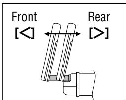
Front-Rear Position
Notes:
- Press [MODE] to return to the regular mode.
- The monitor position setting menu is automatically closed if no operation is performed for about 60 seconds.
- Vertical angle (TILT) and front-rear position data are saved in the memory, so when the display unit is drawn out next, it is automatically set at the angle and in the position adjusted before.
After adjusting its angle, also adjust the brightness to make it easy for you to watch. (→ page 38) - The display position can also be set on the main menu screen. (→ page 30)
Display Unit Lateral Angle Adjustment
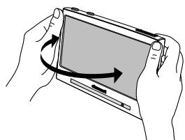
Hold the display unit by the non-slip part in the upper half of it, and adjust its lateral angle.
Caution: There is the danger of your fingers being pinched if you hold the unit by lower part. Hold the unit by the upper half of it, and move it carefully without applying undue force.
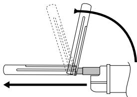
Folding Down the Display Temporarily
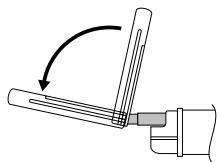
Fold Down: Press [TILT] on the display unit.
Raise: Press [TILT] again on the display unit.
Note: Even when the unit is power off, you can fold down the display temporarily.
Caution: Do not place any object on the display unit, or subject it to undue force.
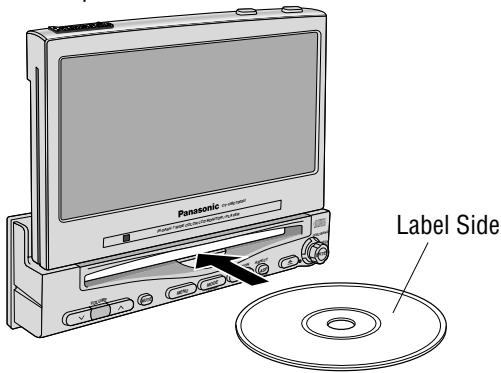
Disc Insert
Playback starts automatically.
Notes:
- Load a CD after making sure that there is no CD in the disc compartment. (If "NO DISC" is displayed while the CD mode is activated, you will find there is not CD in the compartment.)
- Loading a CD when the power is off will turn the power on.
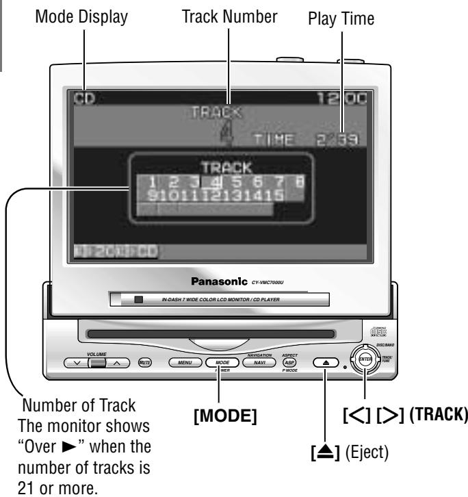
Disc Eject
Press [▲] to stop playback and eject the CD.
When CD is in the player
Press [MODE] to change to CD player mode and playback starts.
Track Selection
[>] (TRACK) : Next track
[ \left[ < \right] ] (TRACK): Beginning of the current track Previous track (Press twice.)
Track Search
Press and hold.
[>] (TRACK) : Fast forward
[<] (TRACK) : Fast backward
Notes :
- You can play a CD even if the monitor is closed.
- If you leave a CD at the CD slot for approximately 30 seconds, the CD is loaded into the compartment automatically after loud beep is energized three times.
Cautions:
- Do not use irregularly shaped CDs.
- Do not insert foreign matter into the disc slots.
Various Way of Listening (Only on the remote control)
Random Play
All the available tracks are played in a random sequence.
Scan Play
The first 10 seconds of each track plays in sequence.
Repeat Play
Repeat the current selection.
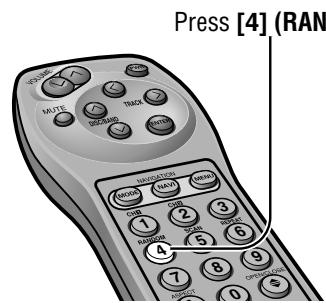
RANDOM
Press [4] (RANDOM) again to cancel.
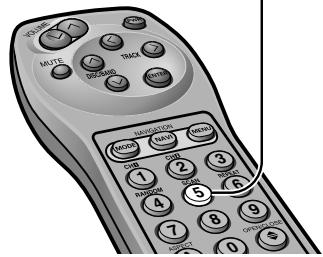
Press [5] (SCAN)
SCAN
With the scanning of all tracks over, the original program starts playing from the beginning.
Press [5] (SCAN) again to cancel.
Press [6] (REPEAT)
REPEAT
Press [6] (REPEAT) again to cancel.
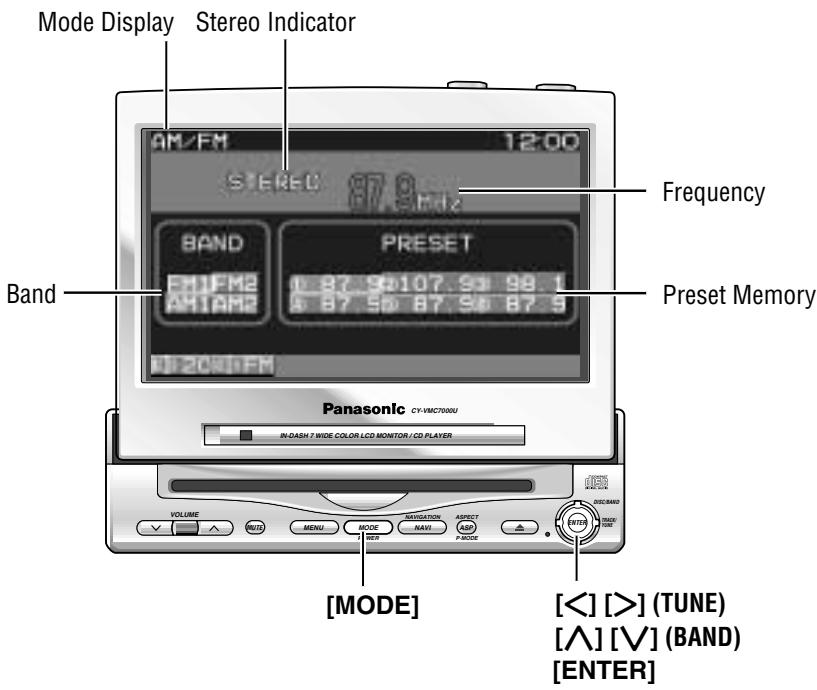
1 Radio Mode Press [MODE] to change to radio mode.
2 Band [A] (BAND) : FM band [V] (BAND) : AM band
3 Tuning [>] (TUNE) : Up [<] (TUNE) : Down
Press and hold [>] (TUNE) or [<] (TUNE) for more than 0.5 seconds, then release. Seeking will start.
Note: The stereo indicator lights during reception of an FM stereo broadcast.
One-touch selection of a station
Up to 6 stations each can be saved in the FM1, FM2, AM1 and AM2 preset station memories.
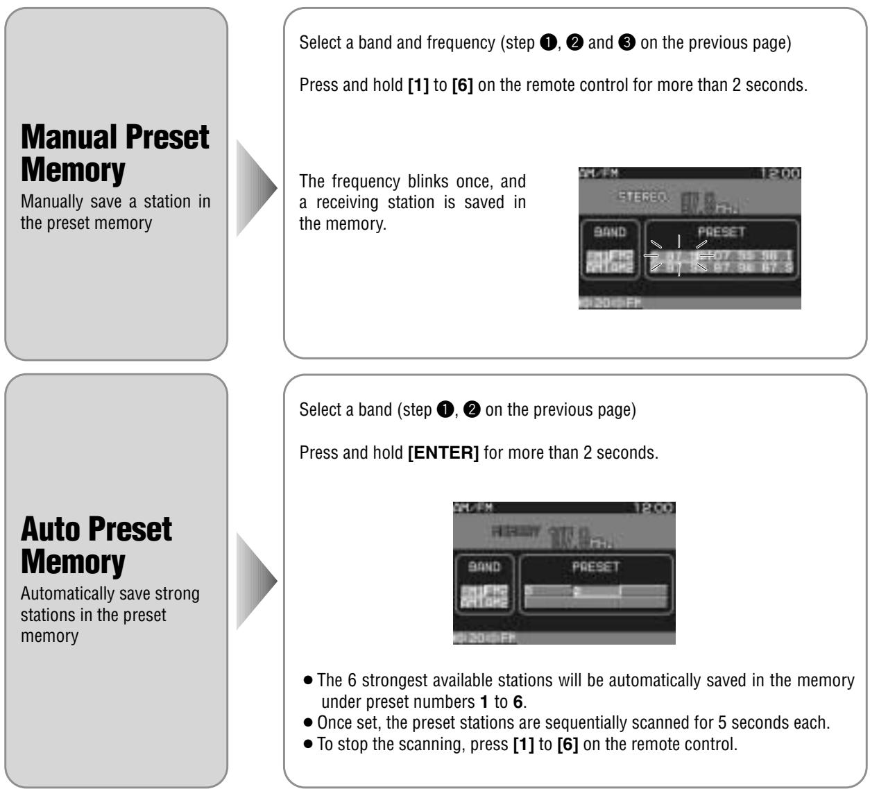

Note: New stations are overwritten on existing saved stations after following this procedure.
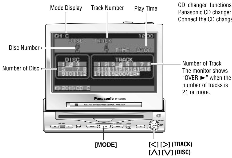
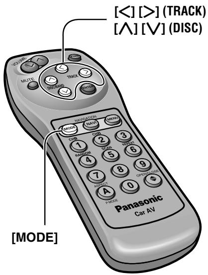
CD changer functions are designed for optional Panasonic CD changer unit.
Connect the CD changer, and load a magazine.
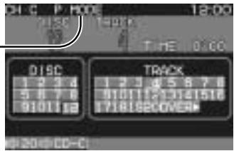
CD Changer Mode
Press [MODE] to change to CD changer mode and playback starts.
Note: Load a magazine with CDs when "NO MAG-AZINE" is displayed.
Disc Selection
[Δ] (DISC): Next disc
[V] (DISC): Previous disc
Track Selection
[>] (TRACK): Next track
[< ] (TRACK) : Beginning of the current track
Previous track (Press twice.)
Track Search
Press and hold.
[>] (TRACK) : Fast forward
[<] (TRACK) : Fast backward
Caution: Do not use irregularly shaped CDs.
Various Way of Listening (Only on the remote control)
Track Random
All the available tracks on all discs in the magazine are played in a random sequence.
Disc Random
All the available tracks on current disc are played in a random sequence.
Track Scan
The first 10 seconds of each track on the discs plays in sequence.
Disc Scan
The first track of all the discs in the magazine is played for 10 seconds each.
Track Repeat
Repeat the current selection.
Disc Repeat
Repeat the current disc selection.
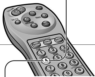
Press [4] (RANDOM).
RANDOM
Press [4] (RANDOM) again to cancel.
D-RANDOM
Press and hold [4] (RANDOM) again to cancel.
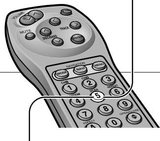
Press [5] (SCAN)
SCAN
With the scanning of all tracks over, the original program starts playing from the beginning.
Press [5] (SCAN) again to cancel.
D-SCAN
With the scanning of all tracks over, the original disc starts playing from the beginning.
Press and hold [5] (SCAN) again to cancel.
Press [6] (REPEAT)
REPEAT
Press [6] (REPEAT) again to cancel.
D-REPEAT
Press and hold [6] (REPEAT) again to cancel.
Picture/Sound from Auxiliary Devices
Car Navigation
Preparation:
- Connect a car navigation system.
- Select a terminal in the "NAVIGATION SET UP" screen according to the terminal actually connected to the car navigation system. ( page 30)
DVD Player
Preparation: Connect a DVD player. (→ page 50)
When you connect a car navigation system through RGB cord [Panasonic Car Navigation (not available yet)]:
Car Navigation ON: Press [NAVI] (NAVIGATION).
Car Navigation OFF: Press [NAVI] (NAVIGATION) again.
Notes:
- When you connect a Panasonic car navigation system with a built-in DVD player, use an RCA cord as well.
- The sound that a Panasonic car navigation system generates comes from the speakers supplied with CY-VMC7000U.
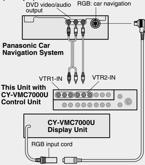
(Example)
When you connect a car navigation system to VTR1-IN or VTR2-IN terminal (other brand's car navigation system):
Car Navigation ON: Press [NAVI] (NAVIGATION).
Car Navigation OFF: Press [NAVI] (NAVIGATION) again.
Or press [MODE] to change to the VTR1 or VTR2 mode.
Select the same mode (VTR1 or VTR2) as the terminal that connected to a car navigation system (VTR1-IN or VTR2-IN).
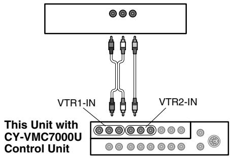
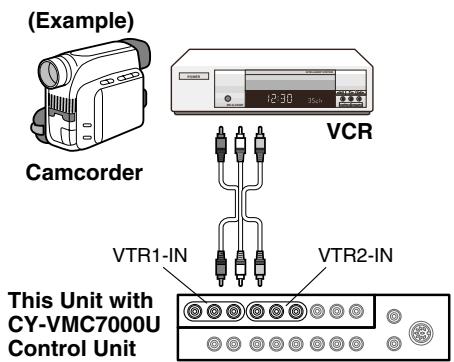
(Example)
Other brand's car navigation system
Press [MODE] to change to the VTR1 or VTR2 mode.
Select the same mode (VTR1 or VTR2) as the terminal that is connected to a DVD video player (VTR1-IN or VTR2-IN).
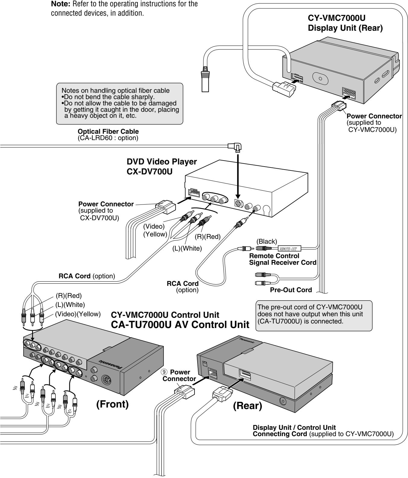
Note: When you connect a Panasonic mobile DVD player (CX-DV700U or CX-DV1500EUC), you can operate it by aiming a remote control, that is supplied with the DVD player, at the remote control sensor of the display unit.
Be sure to connect a remote control signal receiver cord.
( page 51)
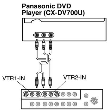
(Example)
This Unit with
CY-VMC7000U
Control Unit
VCR / Camcorder
Preparation: Connect a VCR or Camcorder. () Operating Instructions for CY-VMC7000U page 46)
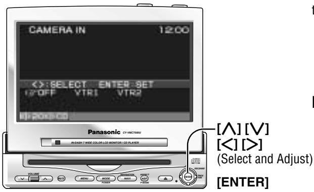
Rear View Camera
Preparation:
- Connect a rear view camera and a reverse lead. ( Operating Instructions for CYVMC7000U page 47)
- Select a terminal in the "CAMERA IN" screen according to the terminal actually connected to the rear view camera. ( page 32)
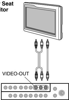
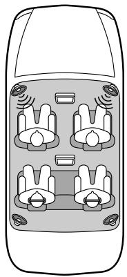
Rear Seat Monitor
You can have different picture and sound at the front monitor and rear monitor at the same time.
Default: AUTO
Preparation: Connect another monitor. ( Operating Instructions for CY-VMC7000U page 44)
Press [MODE] to change to the VTR1 or VTR2 mode.
Select the same mode (VTR1 or VTR2) as the terminal that is connected to a VCR or Camcorder (VTR1-IN or VTR2-IN).
Shift the transmission gear into the reverse position.
The display shows a picture from the rear view camera.
Notes:
- You can see a picture from the rear view camera even if the power of the display unit is inactivated.
- You can see a picture from the rear view camera if you change the mode to the same one (VTR1 or VTR2) as the terminal to which the rear view camera was connected (VTR1-IN or VTR2-IN).
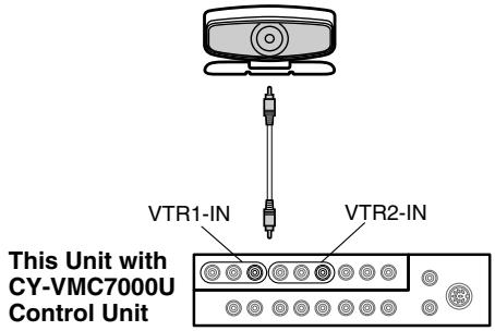
(Example)
Rear View Camera
Press and hold [MENU] for more than 2 seconds.
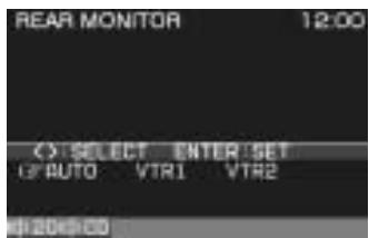
Rear Monitor Setting Menu
(Example)
Rear Seat Monitor
Press [> or [ ] to select an item.
AUTO : Picture and sound come out. These are in the same mode as the front seat monitor.
VTR1 : Picture and sound in the VTR1 mode always come out.
VTR2 : Picture and sound in the VTR2 mode always come out.
This Unit with
CY-VMC7000U
Control Unit
3 Press [ENTER] to set.
Notes:
- Press [MENU] or [MODE] to return to the regular mode.
- The display returns to the previous one if there is no operation for 60 seconds, after changing to the rear monitor setting menu.
- Picture and sound from the car navigation system connected to an RGB are not available at the rear monitor.
- The sound in the CD, radio and CD changer modes is not available at the rear seat monitor.
- You can mute the sound from the rear speakers connected to the front seat monitor, so that you can have different modes at the front seat monitor and the rear seat monitor. (→ page 28)
Useful Functions
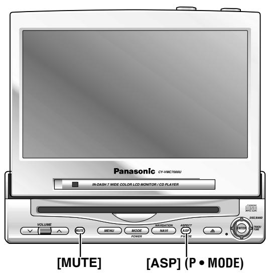
[ASP] (ASPECT)
Aspect Ratio (for VTR Mode)
Default:Normal
Mode: 4 types
Press [ASP] (ASPECT) on the display unit or press [A] (ASPECT) on the remote control to change the aspect ratio as follows.
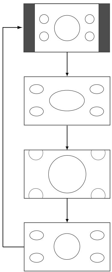
Normal
- The conventional display image has a 4 to 3 ratio of horizontal to vertical.
- In this case, a blank area remains on the right and left sides of the display.
Full
- The screen is extended horizontally as a whole to the aspect ratio of 16 to 9.
- The extension ratio is the same at any point of the screen.
Zoom
- The screen is fully extended at the normal aspect ratio of 4 to 3.
- The top and bottom of the screen are slightly cut.
Just
- The screen is extended horizontally to the aspect ratio of 16 to 9.
- The extension ratio increases toward the right and left ends of the screen.
Notes:
- This adjustment is common to VTR1 and VTR2.
- You can not change the aspect in the menu screen and a screen in the CD mode. These are fixed to "Full".
- The "Zoom" and "Just" screens do not apply to car navigation images.
- When the rear view camera is in operation with the transmission gear shift in the reverse position, the image is shown on the "Full" screen only.
- In some cases, the picture looks different from the original one due to your selection of aspect.
Cautions:
- This is to remind you that compression or extension of the screen using the aspect ratio (screen mode) changing function of this product for commercial purpose of profit making or viewing / listening by the public could infringe on the rights of the author protected by the copyright law.
- If you expand normal picture (4 to 3) by using "Just", "Zoom" or "Full" aspect to the full of the screen, you might not see the periphery of the picture, or you might see deformed picture. Therefore, use the "Normal" mode when you see original picture in deference to picture-making purpose.
Private Mode
Default:OFF
Tone Enhancement (LOUD)
Default:ON
You can mute the sound from the rear speakers connected to the front seat monitor, when you have different modes at the front seat monitor and the rear seat monitor, after connecting the rear seat monitor.
You can enjoy the sound from the rear seat monitor by using headphones.
Private Mode ON: Press and hold [ASP] (P • MODE) for more than 2 seconds. (On the display unit)
Press and hold [A] (P · MODE) for more than 2 seconds. (On the remote control)
Private Mode OFF: Press and hold [ASP] (P • MODE) again for more than 2 seconds. (On the display unit)
Press and hold [A] (P · MODE) again for more than 2 seconds. (On the remote control)
“P·MODE” indicator lights when the Private Mode is activated.
Notes:
- It is not possible to choose and set the BAL/FAD from the SOUND menu while Private Mode is activated.
- When MAIN-IN is set to ON, Private Mode will be inactivated.
When listening at low or medium volume, enhance bass and trebles tones.
LOUD ON: Press and hold [MUTE] for more than 2 seconds.
LOUD OFF: Press and hold [MUTE] again for more than 2 seconds.


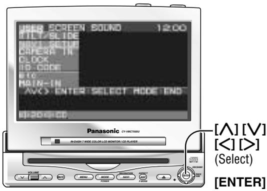
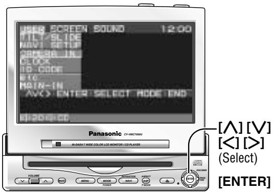
Press [MENU] to display the main menu.

① Press [> or [ ] to select "USER". Press [ ] or [ ] to select an item.
② Press [ENTER] to set.
Monitor Position
Default:TILT...3
SLIDE...Front
Setting range : TILT...1 to 5
SLIDE...Front, Rear
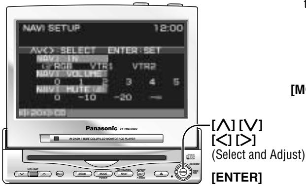
Navigation Set Up
Default:Navigationinput...RGB
Navigation volume ... 4
Navigation mute level ... -10 dB
Note: You can set the Navigation volume and Navigation mute level when "RGB" is selected on Navigation input.
Select
USER
Select
TILT / SLIDE
Select
NAVI SETUP

① Press [> , [<] , [] or [] to select and adjust.
② Press [ENTER] to set. (for NAVI SET UP)
Notes:
- Press [MODE] to return to the regular mode.
- The display returns to the previous one if there is no operation for more than 60 seconds after changing to the setting / adjusting menu.
The monitor position setting menu can also be displayed by pressing the [TILT] button on the display unit for more than 1 second. (For details, refer to page 15.)
Tilting angle adjustment: 1 2 3 4 5
Front-rear position : FRONT REAR
Notes:
- For smooth adjustment, make sure to first return the lateral angle to the neutral position and then adjust the tilt angle.
- Front-rear position "REAR" and tilt angle "5" cannot be selected at the same time.
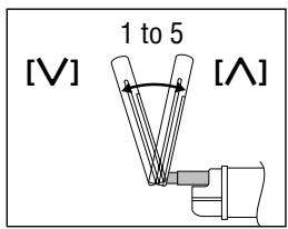
Tilt Angle
Front-Rear Position
NAVI IN
Navigation Input
RGB
: Connected to the RGB input cord, or a car navigation system not connected
VTR1
Connected to the VTR1-IN
VTR2
Connected to the VTR2-IN
NAVI VOLUME
Navigation Volume
0 : The sound that a Panasonic car navigation system (not available yet) generates does not come out.
NAVI MUTE(dB)
Navigation Mute Level
Select the mute level of this unit during the voice guidance from the Panasonic car navigation system (not available yet).
Preparation: Connect the navi mute cord.
0
:Unchanged
-10
: Decrease to 1/3
-20
: Decrease to 1/10
-∞
: No sound

Press [MENU] to display the main menu.

① Press [> or [ ] to select "USER". Press [ ] or [ ] to select an item.
② Press [ENTER] to set.

Rear View Camera Set Up
Default:OFF
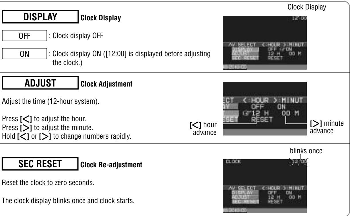
Clock Setting
Default:Clockdisplay...OFF
Select
USER
Select
CAMERA IN
Select
CLOCK

① Press [] , [ < ] [A] or [V] to select and adjust.
② Press [ENTER] to set.
Notes:
- Press [MODE] to return to the regular mode.
- The display returns to the previous one if there is no operation for more than 60 seconds after changing to the setting / adjusting menu.
OFF : Unconnected
VTR1 : Connected to the VTR1-IN
VTR2 : Connected to the VTR2-IN
Notes:
- Make sure to select "OFF" when no rear view camera is connected.
- In case using an optional rear view camera, the reverse lead must be connected.

Press [MENU] to display the main menu.

① Press [ ] or [ ] to select "USER". Press [ ] or [ ] to select an item.
② Press [ENTER] to set.
ID Code setting
Prior to operating this unit, it is advisable to assign your 4-digit ID code for security. (Make sure to use four digits for ID code. ID code can not be set with two or three digits.) Once the ID code has been set, the unit cannot be operated if the main power supply is disconnected then re-connected. It is electronically locked so that a thief could not use the stolen unit unless that person knows the code you have set.
The ID code operation must be performed only by the person whom the unit belongs to.
Generally, it is not necessary to enter the ID code each time when using the unit if it has never been disconnected from the main power supply (car battery).
Caution: Record your registered ID code and keep it in a secure location. If you forget it, you will be unable to use the unit. In case that you can not operate the unit because of forgetting the ID code, please consult your nearest Panasonic Servicenter.
Note: Refer to ID Code Input regarding how to enter the ID code (→ page 11).
Select
USER
Select
ID-CODE

Enter an ID code by using the remote control.
Note: Press [MODE] to return to the regular mode.
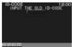
How to Set Your ID Code (For the First Time)
① Enter an ID code of 4 digits using the buttons [0] to [9] on the remote control.
Note: When you are setting your ID code for the first time, it is not necessary to enter the old ID code.
② Enter the ID code of 4 digits again using the buttons [0] to [9] on the remote control.
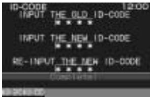
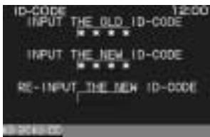
How to Change Your ID Code
① Enter the preset (old) ID code of 4 digits using the buttons [0] to [9] on the remote control. If the wrong ID code is entered, a new ID code cannot be registered.
② Enter a new ID code of 4 digits using the buttons [0] to [9] on the remote control.
③ Enter the new ID code of 4 digits again using the buttons [0] to [9] on the remote control.
How to Cancel the Known ID Code
Note: Should your unit ever require service, cancel your ID code before sending for repair.
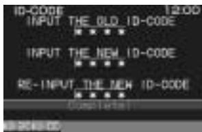
How to Cancel the Known ID Code
① Enter the preset (old) ID code of 4 digits using the buttons [0] to [9] on the remote control. If the wrong ID code is entered, it is not possible to cancel the ID code function.
(2) Press and hold [ENTER] until display the "Complete!".
The ID code cancelling procedure is completed. The unit now works without an ID code.

Press [MENU] to display the main menu.

① Press [ ] or [ ] to select "USER". Press [ ] or [ ] to select an item.
② Press [ENTER] to set.

Button Operation Sound
Default:ON
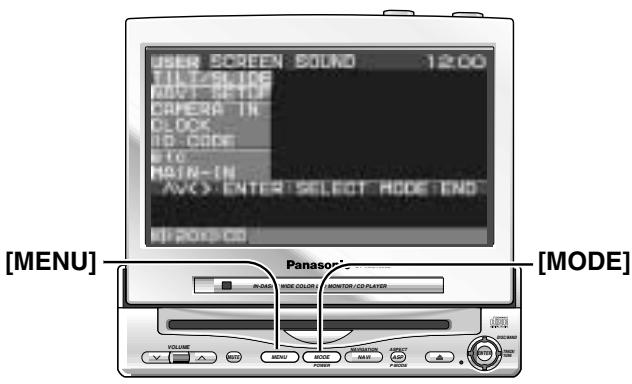
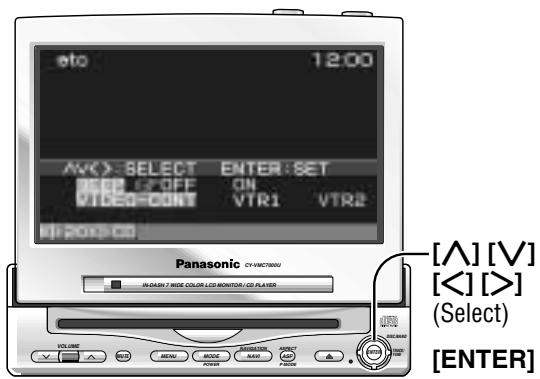
Video Control Setting
This "Video Control Setting" is required when you connect a Panasonic car navigation system with a built-in DVD player. (not available yet)
Default: VTR1
Select
USER
Select
etc
Main Input
This setting is required when you connect a Panasonic digital surround processor (CY-AC300).
Default:OFF

Select
MAIN - IN

① Press [> , [] , [] or [] to select.
② Press [ENTER] to set.
Notes:
- Press [MODE] to return to the regular mode.
- The display returns to the previous one if there is no operation for more than 60 seconds after changing to the setting / adjusting menu.
BEEP
Beep Setting
OFF
Operation sound (Beep) OFF
ON
Operation sound (Beep) ON
Note: The loud beep is energized when opening or closing the display unit even if you select OFF for the beep setting.
VIDEO-CONT
Video Control Setting
VTR1
Connected to the VTR1-IN
VTR2
Connected to the VTR2-IN
Note: Select a terminal connected to the DVD output terminal of a Panasonic car navigation system with a built-in DVD player (not available yet) through an RCA cord.
OFF
: No use of MAIN-IN (front/rear) terminal
ON
: Use of MAIN-IN (front/rear) terminal
Note : Be sure to select “OFF” when you do not connect a digital surround processor (CY-AC300). If you select “ON”, sound does not come from the speakers.
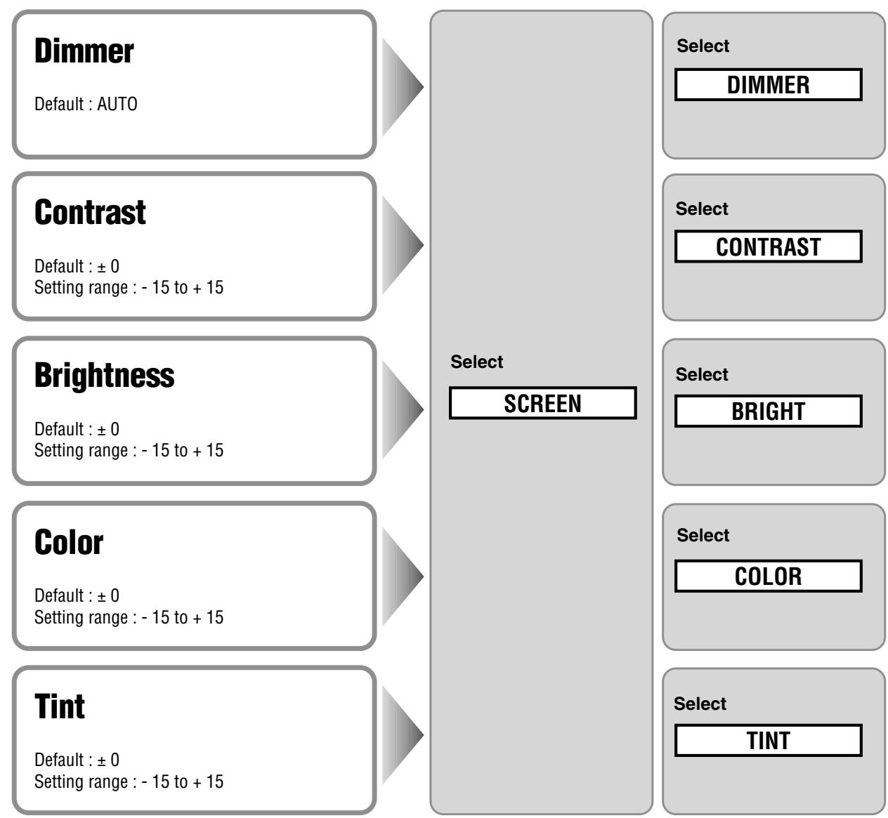
Display Settings

Press [MENU] to display the main menu.

① Press [ ] or [ < ] to select "SCREEN". Press [ ] or [ ] to select an item.
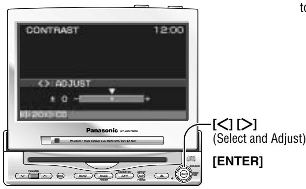
② Press [ENTER] to set.
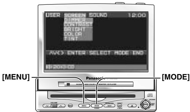
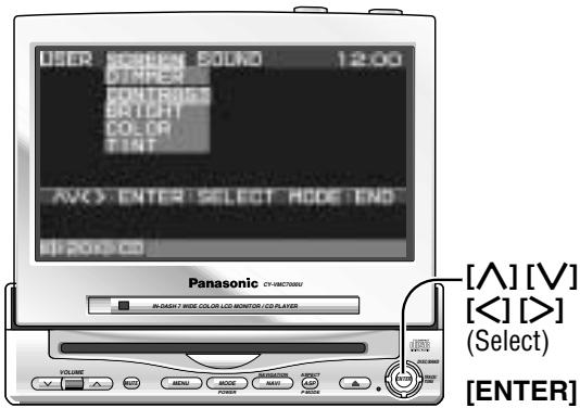

Press [> or [ ] to select and adjust.
Notes:
- Press [MODE] to return to the regular mode.
- The display returns to the previous one if there is no operation for more than 60 seconds after changing to the setting / adjusting menu.
AUTO
: Automatically adjusted according to ambient light intensity.


ker (1) to Brighter (4).
Press [ENTER] to set.
Decrease the contrast between black and white.
Increase the contrast between black and white.
Darken
Lighten

Lighten the depth of color on the display
Deepen the depth of color on the display

Emphasize red in the color image
Emphasize green in the color image

Press [MENU] to display the main menu.

① Press [> or [ ] to select "SOUND". Press [ ] or [ ] to select an item.
② Press [ENTER] to set.
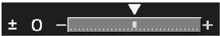
Bass / Treble
Default: ±0 dB
Setting range: -12 dB to +12 dB by 2 dB step
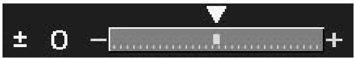
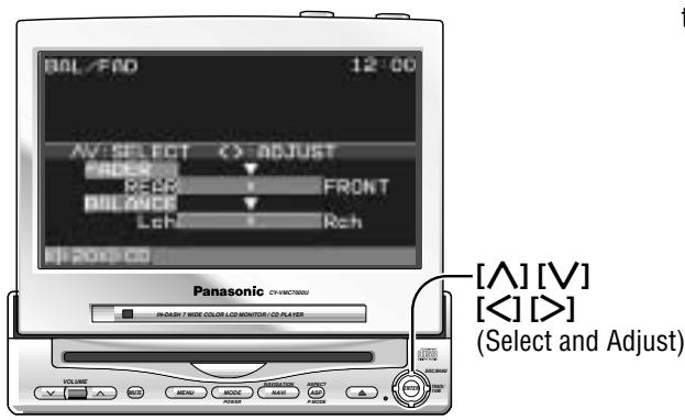
Balance / Fader
Default:Center
Setting range :15 levels for each
Select
SOUND
Select
TONE
Select
BAL/FAD

Press [> , [<] , [] or [] to select and adjust.
Notes:
- Press [MODE] to return to the regular mode.
- The display returns to the previous one if there is no operation for more than 60 seconds after changing to the setting / adjusting menu.
BASS
Bass Adjustment

Decrease the bass level.
Increase the bass level
TREBLE
Bass Adjustment

Decrease the treble level
Increase the treble level
FADER
Fader

Rear enhanced
Front enhanced
BALANCE
Balance

Left enhanced
Right enhanced

WARNING
This installation information is designed for experienced installers and is not intended for non-technical individuals. It does not contain warnings or cautions of potential dangers involved in attempting to install this product.
Any attempt to install this product in a motor car by anyone other than qualified installer could cause damage to the electrical system and could result in serious personal injury or death.
Overview
This product should be installed by a professional. However, if you plan to install this product yourself, your first step is to decide where to install it. The instructions in these pages will guide you through the remaining steps: (Please refer to the "WARNING" statement above).
- Identify and label the car wires.
- Connect the car wires to the wires of the power connector.
Install the unit. - Check the operation of the unit.
If you encounter problems, please consult your nearest professional installer.
Caution: This unit operates with a 12 volt DC negative ground auto battery system only. Do not attempt to use it in any other system. Doing so could cause serious damage.
Before you begin installation, look for the items on the right which are packed with your unit.
- Warranty Card ....... Fill this out promptly.
- Panasonic Servicenter for Service Directory ....... Keep for future reference in case the product needs servicing.
- Installation Hardware ....... Needed for installation
Installation Hardware
| No. | Item | Diagram | Qty |
| ① | Binding-Head Screw (M3 x 6 mm) | 2 | |
| ② | Binding-Head Screw (M5 x 8 mm) | 4 | |
| ③ | Tapping Screw (M6 x 20 mm) | 4 | |
| ④ | Hex. Nut (M5) | 4 | |
| ⑤ | Mounting Bracket | 2 | |
| ⑥ | Base Bracket | 2 | |
| ⑦ | Double-Faced Adhesive Tape | 2 | |
| ⑧ | Velcro Tape | 2 | |
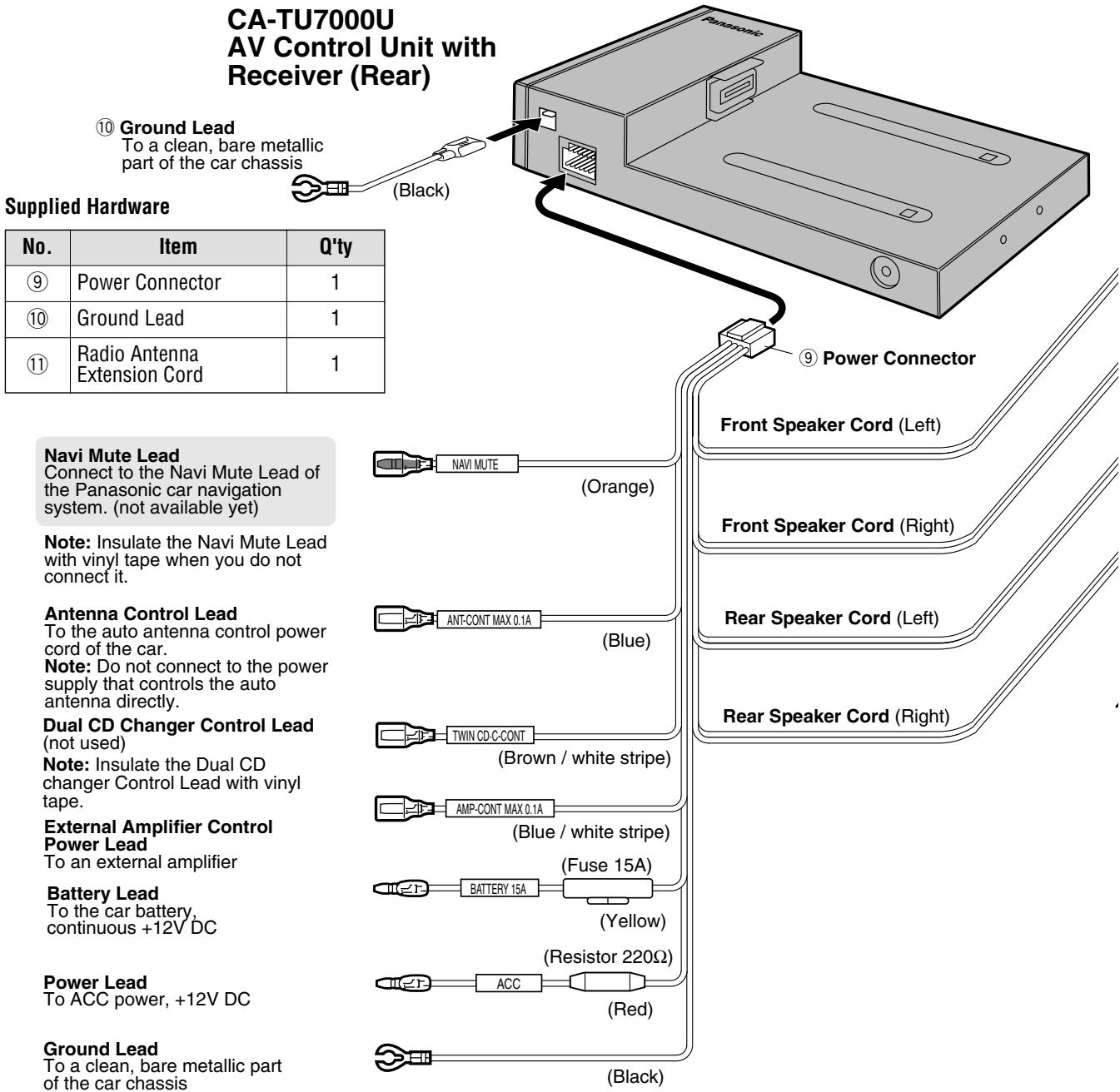
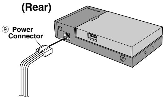
| ⑨ | Power Connector | 1 | |
| ⑩ | Ground Lead | 1 | |
| ⑪ | Radio Antenna Extension Cord | 1 |
Before Installation
Warning
- Do not install the monitor in a location which obstructs driving, visibility or which is prohibited by applicable laws and regulations. If the monitor is installed in a location which obstructs forward visibility or operation of the air bag or other safety equipment or which interferes with operation of the vehicle, it may cause an accident.
- Never use bolts or nuts from the vehicle's safety devices for installation. If bolts or nuts from the wheel, brakes or other safety devices are used for installation of the monitor, it may cause an accident.
- Attach the wires correctly. If the wiring is not correctly performed, it may cause a fire or an accident. In particular, be sure to run and secure the lead wire so that it does not get tangled with a screw or the moving portion of a seat rail.
- Use with 12 volt DC negative ground vehicle. This unit is only for use with a 12 volt DC negative ground vehicle. It cannot be used in large trucks or diesel vehicles which are 24 volt DC vehicle. If it is used in the wrong type of vehicles, it may cause a fire or an accident.
Caution
- Use the specified fuse. Be sure to always use the specified fuse. If a fuse other than the specified fuse is used, it may cause a fire or an accident.
- Do not damage the cord by pinching or pulling it. Do not pull or damage the cord. If the cord is not treated properly, it will short out or be severed and may cause a fire or an accident.
Required Tools
You'll need a screwdriver, a 1.5 volt AA battery, and the following:
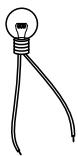
12 V DC Test Bulb
Electrical Tape
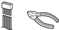
Side-Cut Pliers


Identify All Leads
The first step in installation is to identify all the car wires you'll use when hooking up your sound system.
As you identify each wire, we suggest that you label it using masking tape and a permanent marker. This will help avoid confusion when making connections later.
Note: Do not connect the power connector to the stereo unit until you have made all connections. If there are no plastic caps on the stereo hooking wires, insulate all exposed leads with electrical tape until you are ready to use them. Identify the leads in the following order.
Power Lead
If your car has a radio or is pre-wired for one :
Cut the connector wires one at a time from the plug (leaving the leads as long as possible) so that you can work with individual leads. Turn the ignition on to the accessory position, and ground one lead of the test bulb to the chassis.
Touch the other lead of the test bulb to each of the exposed wires from the cut radio connector plug. Touch one wire at a time until you find the outlet that causes the test bulb to light.
Now turn the ignition off and then on. If the bulb also turns off and on, that outlet is the car power lead.
If your car is not wired for an audio unit :
Go to the fuse block and find the fuse port for radio (RADIO), accessory (ACC), or ignition (IGN).
Battery Lead
If your stereo unit has a yellow lead, you will need to
Installation Guide (continued)
locate the car's battery lead. Otherwise you may ignore this procedure. (The yellow battery lead provides continuous power to maintain a clock, memory storage, or other functions.)
If your car has a radio or is pre-wired for one:
With the ignition and headlights off, identify the car battery lead by grounding one lead of the test bulb to the chassis and checking the remaining exposed wires from the cut radio connector plug.
If your car is not wired for an audio unit :
Go to the fuse block and find the fuse port for the battery, usually marked BAT.
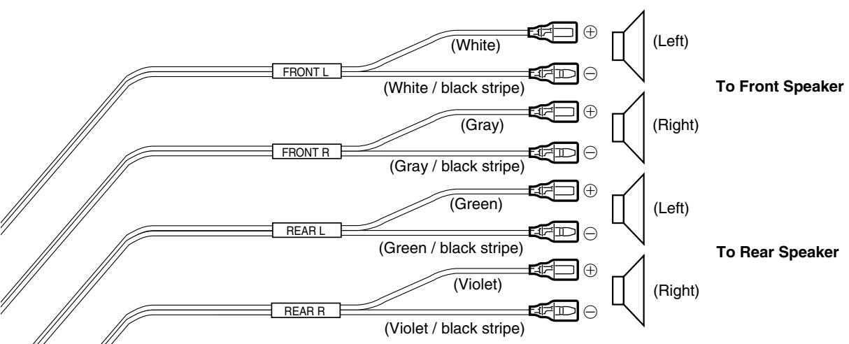
Speakers
Identify the car speaker leads. There will be two leads for each speaker, usually color coded.
A handy way to identify the speaker leads and the speaker they connect with is to test the leads using a 1.5 V AA battery as follows.
Hold one lead against one pole of the battery and stroke the other lead across the other pole. You will hear a scraping sound in a speaker if you are holding a speaker lead.
If not, keep testing different lead combinations until you have located all the speaker leads. When you label them, include the speaker location for each.
Connect All Leads
Now that you have identified all the wires in the car, you're ready to begin connecting them to the stereo unit wires. The connection diagram ( Page 48) shows the proper connections and color coding of the leads.
We strongly recommend that you test the unit before making a final installation.
You can set the unit on the floor and make temporary connections to test the unit. Use electrical tape to cover all exposed wires.
Important: Connect the red power lead last, after you have made and insulated all other connections.
Ground
Connect the black ground lead of the power connector to the metal car chassis.
Speakers
Connect the speaker wires. See the wiring diagram for the proper hookups. Follow the diagram
carefully to avoid damaging the speakers and the stereo unit.
The speakers used must be able to handle more than 45W of audio power. If using an optional audio power, the speakers should be able to handle the maximum amplifier output power. Speakers with low input ratings can be damaged.
Speaker impedance should measure 4 - 8 Ω, which is typically marked on most speakers. Lower or higher impedance speakers will affect output and can cause both speaker and stereo unit damage.
Caution: Never ground the speaker cords. For example, do not use a chassis ground system or a three-wire speaker common system. Each speaker must be connected separately using parallel insulated wires. If in doubt about how your car's speakers are wired, please consult with your nearest professional installer.
Motor Antenna
Connect the vehicle motor antenna lead to the blue motor antenna relay control lead.
Battery
Connect the yellow battery lead to the correct radio wire or to the battery fuse port on the fuse block.
Antenna
Connect the antenna by plugging the antenna lead into the antenna receptacle.
Equipment
Connect any optional equipment such as an DVD video player according to the instructions furnished with the equipment. Read the operating and installation instructions of any equipment you will connect to this unit.
Power
Connect the red power lead to the correct car radio wire or to the appropriate fuse port on the fuse block.
If the stereo unit functions properly with all these connections made, disconnect the wires and proceed to the final installation.
Final Installation
Lead Connections
Connect all wires, making sure that each connection is insulated and secure. Bundle all loose wires and fasten them with tape so they won't fall down later.
Congratulations! After making a few final checks, you're ready to enjoy your new auto stereo system.
Final Checks
- Make sure that all wires are properly connected and insulated.
- Turn on the ignition to check the unit for proper operation.
If you have difficulties, consult your nearest authorized professional installer for assistance.
Precautions
We strongly recommend that you wear gloves for installation work to protect yourself from injuries.
- Disconnect the cable from the negative (-) battery terminal (see caution below).
- Unit should be installed in a horizontal position with the front end up at a convenient angle, but not more than 30^ .
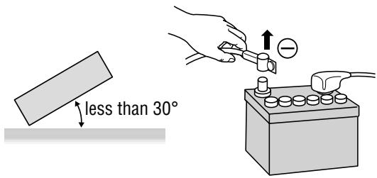
Caution : Do not disconnect the battery terminals of a car with trip or navigational computer since all user settings stored in memory will be lost. Instead take extra care with installing the unit to prevent shorts.
This unit should be professionally installed. In case of difficulty, please consult with your nearest professional installer.
- This unit only operates in a 12-volt DC negative ground system.
- Follow the electrical connections carefully ( Page 48 to 52). Failure to do so may result in damage to the unit.
- Connect the power lead after all other connections are made.
- Be sure to connect the battery lead (yellow) to the positive terminal (+) of the battery or fuse block (BAT) terminal.
- Insulate all exposed wires to prevent short circuiting.
- Secure all loose wires after installing the unit.
- Please carefully read the operating and installation instructions of the respective equipment before connecting it to this unit.
Caution: Please follow the laws and regulations of your state, province or country for installation of the unit.
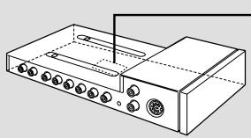
Mounting the AV Control Unit
Remove the cover.
- Remove the cover from the control unit of the head unit (CY-VMC7000U).
- Remove Velcro tape from the bottom of the control unit of the head unit (CY-VMC7000U) if any.
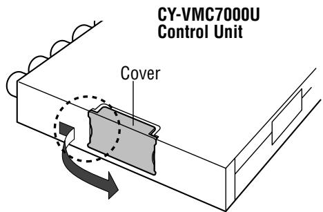
Hook the cover with your nail.
Slide the cover and remove it.
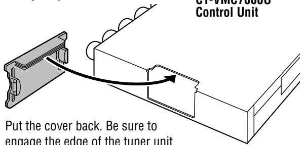
When you put the cover back
with the cover.
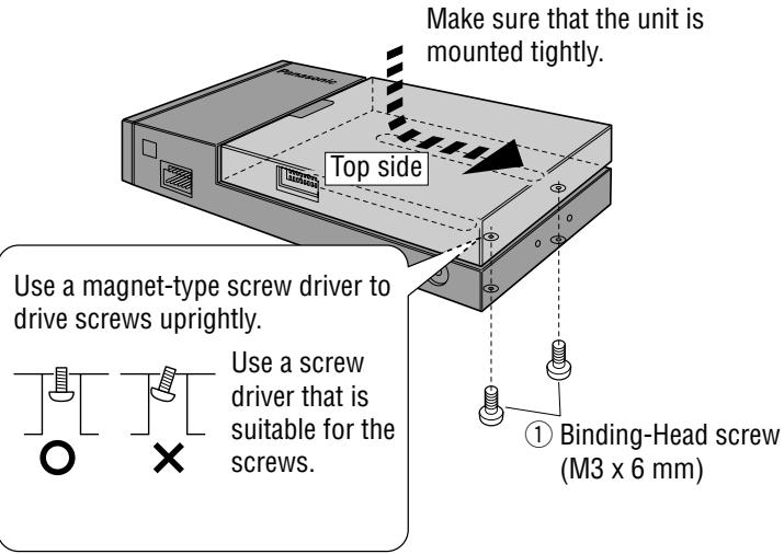
1 Connect the control unit of the head unit (CY-VMC7000U) to this unit (CA-TU7000U).
1 Slide the unit along the guides, and insert the connector in this unit securely.
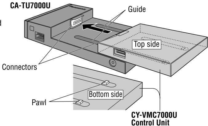
Make sure that the pawls on the bottom of the control unit of the head unit are in position. Try to move the control unit by pressing the topside of it as shown with the arrow in the figure.
Drive two Binding-Head Screws ① from the bottom of the AV control unit to fix it. Make sure to fix it firmly.

Installation
Cautions:
- Never mount the unit in any of the following locations to avoid damage due to overheating;
- Near the heater port.
- Places like the dashboard or rear deck, where it may be exposed to direct sunlight.
- Do not mount the unit near the door, where it could be exposed to rain.
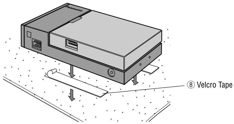
Mount the unit on the car carpet by using Velcro Tape ⑧.
Attach the seal side of the Velcro Tape ⑧ to the AV control unit, then mount the unit on the carpet.
Note: Some carpet materials may not be suitable for this mounting method. In this case, please contact your nearest Panasonic Servicenter for installation.
□ Unit installation by using the Mounting Brackets ⑤ and the Base Brackets ⑥.
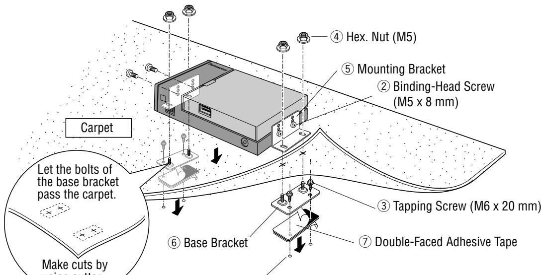
Drill for 4.8mm diameter holes to the chassis.
* Put the tape and the base bracket together with each hole of the tape and bracket connected so that the screw goes in at two positions.
Note : Apply an anticorrosive to the holes and tapping screws.
Caution: You run the risk of interfering with the mounting or causing damage by drilling into the gas tank, a wiring harness, or other component.
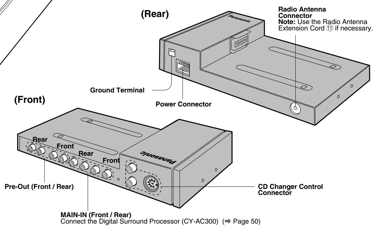
Wiring Diagram
Cautions:
- This product is designed to operate off a 12 volt, negative ground battery system.
- To prevent damage to the unit, be sure to follow the connection diagram below.
- Remove approx. 1/4'' (5mm) of protective covering from the ends of the leads before connecting.
- Do not insert the power connector into the unit until the wiring is completed.
- Be sure to insulate any exposed wires from a possible short-circuit from the car chassis. Bundle all cables and keep cable terminals free from touching any metal parts.
- Remember, if your car has a drive computer or a navigation computer, the data of its memory may be erased when the battery terminals are disconnected.
Cautions:
- Ask a qualified service person for installation and wiring.
The installation and wiring of this unit requires special skills and experience. For safety, ask the store where you purchased it to perform its installation and wiring. - Do Not Disassemble or Modify.
Do not disassemble or modify the unit. Do not remove the coverings from the ends of cables and wires to provide power for other devices. Because it may generate smoke or fire, and cause electric shock or trouble.
Example: Connection with DVD Player (CX-DV700U) and Digital Surround Processor (CY-AC300)
- Set the MAIN-IN to ON when the digital surround processor is connected. (→ Page 36)
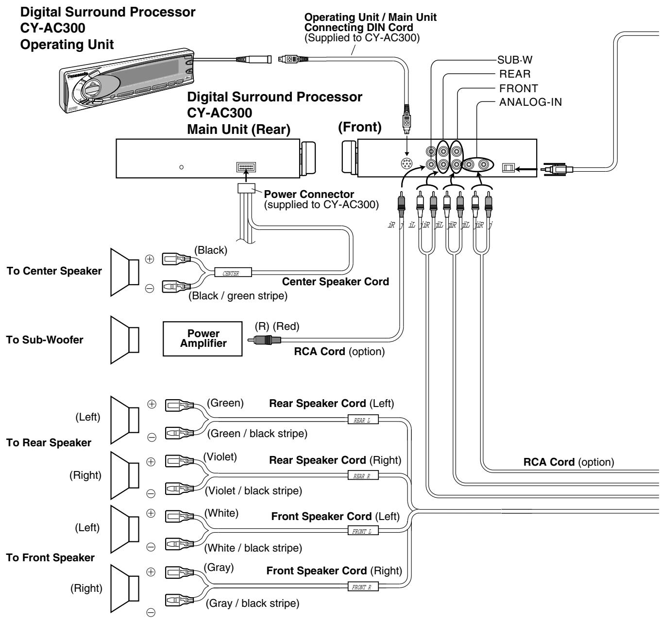
Note: Refer to the operating instructions for the connected devices, in addition.
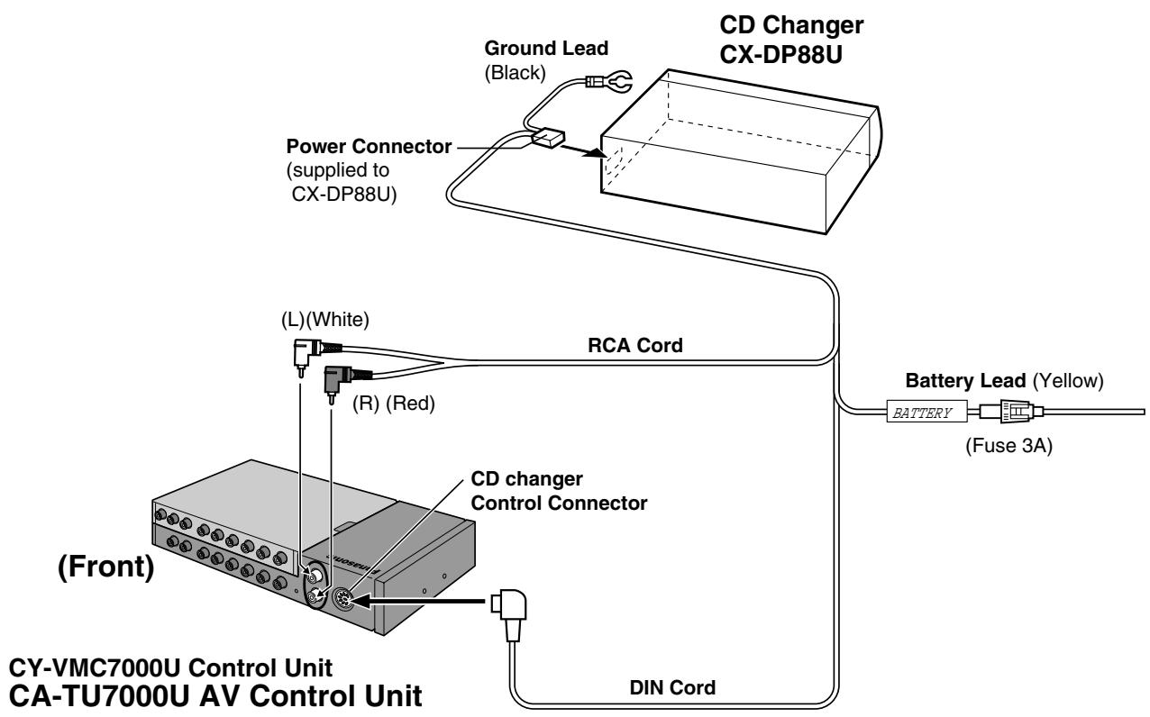
Example: Connection with CD Changer (CX-DP88U)
Note: Refer to the operating instructions for the connected devices, in addition.
Preliminary Steps
Check and take steps as described in the tables below.
If You Suspect Something Wrong
Immediately switch power off.
Disconnect the power cable and check that there is neither smoke nor heat from the unit before asking for repairs. Never try to repair the unit yourself because it is dangerous to do so.
Cautions:
- Do not use the unit if it malfunctions or is something wrong.
- Do not use the unit in an irregular condition, for example, without sound, or with smoke or foul smell, can cause ignition or electric shock. Immediately stop using it and call the store where you purchased it.
Note : Refer to the operating instructions of the head unit (CY-VMC7000U) with regard to Remedy.

Common
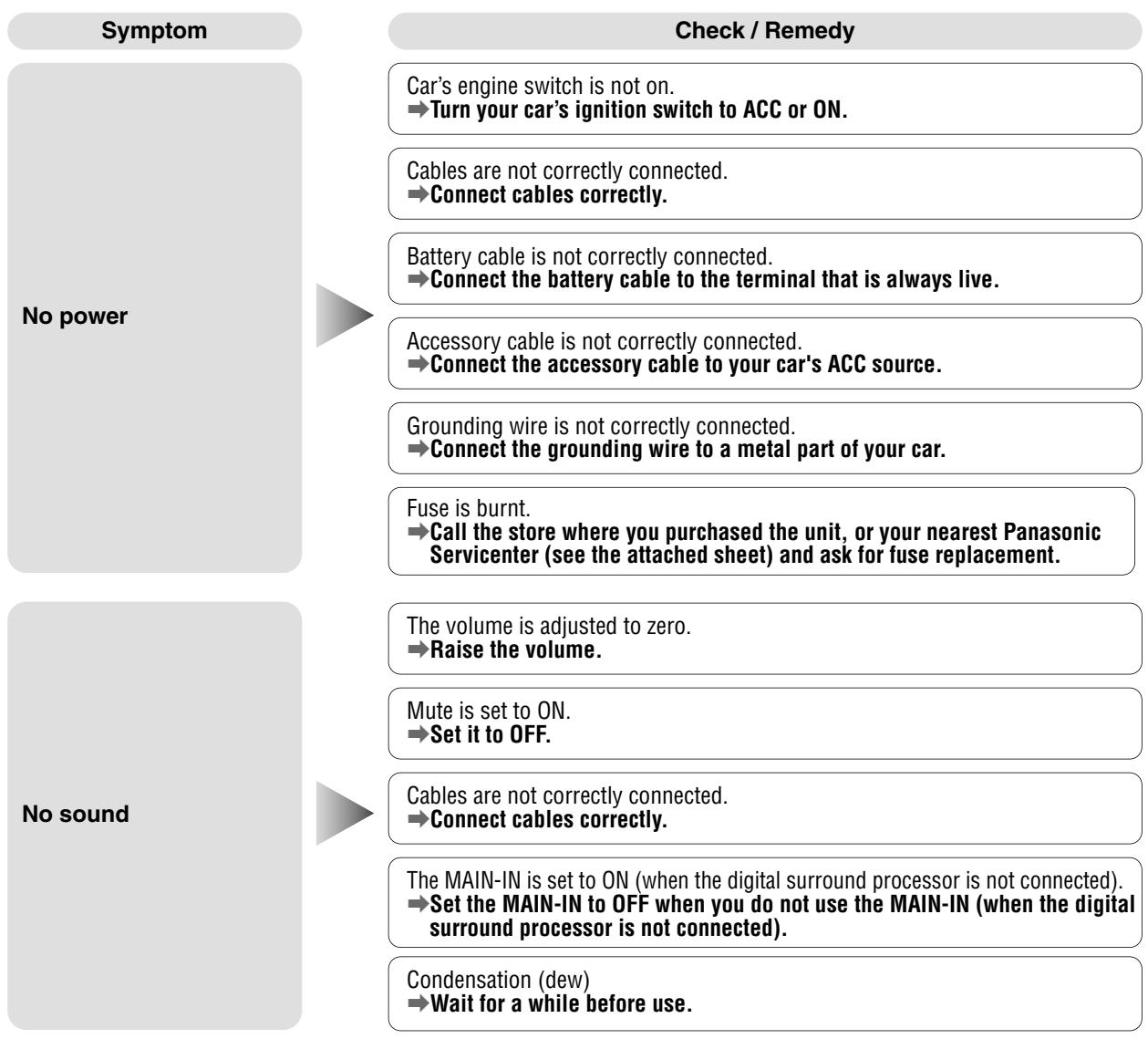
Troubleshooting (continued)
| Symptom | Check / Remedy |
| Only sound, no picture. | Side brake cord is not correctly connected. →Connect the side brake cord correctly. |
| You did not pull the parking brake lever. →Pull the parking brake lever. | |
| Noise Picture is not clear. | You are using a cellular phone near the unit. →Keep some space between the unit and your cellular phone. |
Monitor
| Symptom | Check / Remedy |
| The tilt angle or the front-rear position of the display is not adjustable. | There is an obstacle. Install the unit where the unit moves freely. |
| The monitor does not go back into the unit. | The monitor direction is not proper. Change the monitor direction to the center. |
| The monitor stops on the way to the home position for some reason. Raise the monitor a little and press [♀] (OPEN/CLOSE). |
CD
| Symptom | Check / Remedy |
| CD is inside but no sound. | CD is upside down. →Place CD in the correction direction, the label side up. |
| CD is dirty. →Clean CD, referring to the section on Notes on CD. | |
| CD sound skips, tone quality is low. | CD is dirty. →Clean CD, referring to the section on Notes on CD. |
| Sound skip due to vibration. | Mounting angle is over 30 degrees. →Adjust mounting angle to less than 30 degrees. |
| Unstable mounting. →Mount the unit securely with the mounting parts, referring to the section on Installation. | |
| CD is not ejected. | ●CD is defective. ●Mechanical trouble. →Press [▲]. If failure persists, press the reset switch. If normal operation is not restored, call the store where you purchased the unit or the nearest Panasonic Servicenter to ask for repairs. |
Radio
Symptom
Much noise in FM stereo and monaural broadcasts.
Preset station is reset.
Check / Remedy
Station is too far, or signals are too weak.
Select other stations of higher signal level.
The radio antenna is not extended enough.
Fully extend the radio antenna.
Battery cable is not correctly connected.
Connect the battery cable to the terminal that is always live.
Car Navigation, DVD Player, VCR, Camcorder, Rear View Camera
Symptom
The picture from a car navigation system is not displayed.
The picture from a DVD player is not dis
The picture from a VCR or a camcorder is not displayed.
The picture from a rear view camera is not displayed.
The picture or the sound of the second monitor is not switchable.
Check / Remedy
The connection of a car navigation system is not correct.
Connect it correctly.
Input setting of a car navigation system is not correct.
Make the input setting correct.
The connection of a DVD player is not correct.
Connect it correctly.
A VCR or Camcorder is not connected correctly.
Connect a VCR or Camcorder correctly.
Rear view camera is not connected correctly.
Connect a rear view camera correctly.
Input setting of a camera is not correct.
Make the input setting correct.
"AUTO" is not selected for the setting of a rear monitor.
Select "AUTO" for the setting.
Display Settings
Symptom
The brightness of the screen is not stable.
The picture is dark. The picture is whitish. Something is wrong with the picture. The picture is light in color.
Red, blue, or green spots appears.
Check / Remedy
"AUTO" dimmer is selected.
Select one of the dimmer levels from among 1 to 4 to make the dimmer adjustment become free from light intensity.
The screen is not adjusted properly.
Make every adjustment of the screen.
This is a characteristic of liquid crystal panels and is not a problem.
Troubleshooting (continued)
Sound Settings
Symptom
No sound from left, right, front, or rear speaker.
Left and right sounds are reversed in stereo listening.
Remote Control
Symptom
Buttons are invalid for operation.
Check / Remedy
Left and right balance, or front and rear balance is off on one side.
Adjust BAL/FAD as appropriate.
Cables are not correctly connected.
Connect the cables correctly.
The right speaker wire is connected to the left speaker and the left speaker wire to the right speaker.
Connect the speaker wires to the correct one.
Check / Remedy
Battery polarities (+) (-) are reversed.
Insert the batteries correctly.
Wrong batteries.
Check the batteries.
Batteries have run down.
Replace the batteries.
Remote control is in the wrong direction.
Direct the remote control at remote control sensor on the display unit.
Error Display Messages
CD / CD Changer
Display
E1
E2
E3
NO DISC
NO MAGAZINE
Check / Remedy
Disc is dirty, or is upside down.
Check disc.
Disc has scratches.
Check disc.
No operation by some cause.
Press [▲]. If failure persists, press the reset switch. If normal operation is not restored, call the store where you purchased the unit or the nearest Panasonic Servicenter to ask for repairs.
No disc is in the player.
Insert disc into the CD slot.
There is no CD-loaded magazine in the changer.
Load the changer with CD-loaded magazine.
Notes:
- There may be cases where the disc numbers affected by an error are displayed before E1 and E2.
- Displays and the steps to be taken for errors vary in part from changer to changer. For details, refer to the Operating Instructions for the changer used.
Maintenance
Your product is designed and manufactured to ensure a minimum of maintenance. Use a dry soft cloth for routine exterior cleaning. Never use benzine, thinner or other solvents.
Product Servicing
If the suggestions in the charts do not solve the problem, we recommend that you take it to your nearest authorized Panasonic Servicenter. The product should be serviced only by a qualified technician.
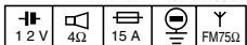
Replacing the Fuse
Use fuses of the same specified rating (15 amps). Using different substitutes or fuses with a higher rating, or connecting the product directly without a fuse, could cause fire or damage to the stereo unit.
If the replacement fuse fails, contact your nearest Panasonic Servicenter for service.
Reset Switch
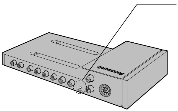
Reset switch
Insert a hard, slender stick into the hole and push the switch. Press the reset switch on the front side of the display unit connected to the head unit (CY-VMC 7000U), too.
The unit returns to the default state when the trouble is reset. Remember, the data and settings stored in the memory are deleted.
Important
Push the switch only when the unit fails to operate with any buttons.
If the unit fails to return to normal condition, call the nearest
Panasonic Servicenter and ask for repairs.
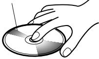
Notes on CD
- Do not touch the underside of the disc.
- Do not make scratches on the disc.
- Do not bend disc.
- When not in use, keep CD in the case.
Do not use irregularly shaped CDs
Do not leave discs in the following places:
- Direct sunlight
Near car heaters - Dirty, dusty and damp areas
- Seats and dashboards
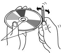
Disc Cleaning
Use a dry, soft cloth to wipe from the center outward.
Caution on New Discs
A new disc may have rough edges on its inner and outer perimeter. These may cause malfunction.
Remove the rough edges using a pencil, etc.
Label side


Do not use irregularly shaped CDs


Rough edge
Notes on CD-R Disc
A playable CD-R disc is only a CD-R disc on which sound was recorded.
- Some recorded CD-R discs by using CD recorder are not playable because of their characteristic, or scratches or dirt on the discs.
- You can not play a CD-R disc that has not been finalized.
- A CD-RW disc is not playable.
- MP3 file, video CD, CD-ROM and CD-EX disc are not playable.
- Be sure to observe the handling instructions of CD-R disc.
- Do not apply a disc that has a label printed by a commercially available label printer.
The specification for CY-VMC7000U are excluded from the following.
General
Power Supply DC 12 V (11 V - 16 V), test voltage 14.4 V, negative ground
Current Consumption Less than 10 A
Rated Output : 18 W x 4 ch (1 kHz, 1%, 4 Ω)
Maximum Power Output : 45 W x 4 ch (at 16 V)
Compatible Speaker Impedance : 4 Ω
Pre-Amp Output Voltage : 4.0 Vrms
Pre-Amp Output Impedance Less than 60 Ω
Dimensions (W x H x D) : 9-5/8" x 1-5/8" x 5-7/8" (245 x 42 x 150 mm)
Weight : 2 lbs. 14 oz. (1.3 kg)
FM Stereo Radio
Frequency Range : 87.9 - 107.9 MHz
Usable Sensitivity 12 dBf
Stereo Separation : 35 dB (1 kHz)
Signal / Noise Ratio : 60 dBf
AM Radio
Frequency Range : 530 - 1,710 kHz
Useable Sensitivity : 28 dB / μV
Image Rejection Ratio : 50 dB
Above specifications comply with EIA standards.
Note: Specifications and the design are subject to modification without notice due to improvements in technology.
Panasonic Consumer Electronics Company, Division of Matsushita Electric Corporation of America
One Panasonic Way, Secaucus, New Jersey 07094
http://www.panasonic.com
Panasonic Sales Company.
Division of Matsushita Electric of Puerto Rico, Inc. ("PSC")
Ave. 65 de Infanteria, Km. 9.5
San Gabriel Industrial Park, Carolina, Puerto Rico 00985
http://www.panasonic.com
Panasonic Canada Inc.
5770 Ambler Drive,
Mississauga, Ontario
L4W 2T3
www.panasonic.ca