Chassis 5500 (2018) - Car DODGE - Free user manual and instructions
Find the device manual for free Chassis 5500 (2018) DODGE in PDF.

| Product Type | Heavy-duty Cab Chassis |
| Make | Dodge (Ram) |
| Model | Chassis 5500 |
| Year | 2018 |
| Engine | 6.7L Cummins Turbo Diesel I6 |
| Horsepower | 325 hp @ 2,800 rpm |
| Torque | 750 lb-ft @ 1,600 rpm |
| Transmission | 6-speed automatic Aisin AS69RC |
| Drivetrain | Rear-wheel drive (4x4 optional) |
| GVWR | 19,500 lbs (8,845 kg) |
| Fuel Type | Diesel |
| Fuel Capacity | 52 gallons (197 L) |
| Maximum Towing Capacity | Up to 37,000 lbs (16,783 kg) with gooseneck |
| Wheelbase Options | 142 in (3,607 mm) to 240 in (6,096 mm) |
| Brakes | 4-wheel disc with ABS |
| Tire Size | 19.5 x 6.75 (steel wheels) or optional 22.5 |
| Oil Capacity (with filter) | 12 quarts (11.4 L) |
| Recommended Oil | SAE 15W-40 CJ-4 or higher |
| Maintenance Interval | Oil change every 7,500 miles (12,000 km) |
| Air Conditioning Refrigerant | R134a (52 oz / 1.47 kg approx) |
Frequently Asked Questions - Chassis 5500 (2018) DODGE
User questions about Chassis 5500 (2018) DODGE
0 question about this device. Answer the ones you know or ask your own.
Ask a new question about this device
Download the instructions for your Car in PDF format for free! Find your manual Chassis 5500 (2018) - DODGE and take your electronic device back in hand. On this page are published all the documents necessary for the use of your device. Chassis 5500 (2018) by DODGE.
USER MANUAL Chassis 5500 (2018) DODGE
text_image
RAM COMMERCIAL2018
CHASSIS CAB
OWNER'S MANUAL

VEHICLESSOLDINCANADA
With respect to any Vehicles Sold in Canada, the name FCA US LLC shall be deemed to be deleted and the name FCA Canada Inc. used in substitution therefore.
DRIVINGANDALCOHOL
Drunken driving is one of the most frequent causes of accidents.
Your driving ability can be seriously impaired with blood alcohol levels far below the legal minimum. If you are drinking, don't drive. Ride with a designated non-drinking driver, call a cab, a friend, or use public transportation.
WARNING!
Drivingafterdrinkingcanleadtoanaccident. Yourperceptionsarelesssharp,yourreflexesare slower,andyourjudgmentisimpairedwhenyou havebeendrinking.Neverdrinkandthendrive.
This manual illustrates and describes the operation of features and equipment that are either standard or optional on this vehicle. This manual may also include a description of features and equipment that are no longer available or were not ordered on this vehicle. Please disregard any features and equipment described in this manual that are not on this vehicle.
FCA US LLC reserves the right to make changes in design and specifications, and/or make additions to or improvements to its products without imposing any obligation upon itself to install them on products previously manufactured.
Copyright © 2018 FCA US LLC


SECTION PAGE
TABLE OF CONTENTS
1 INTRODUCTION....3
2 GRAPHICALTABLEOFCONTENTS. 9
3 GETTINGTOKNOWYOURVEHICLE. 15
4 GETTINGTOKNOWYOURINSTRUMENTPANEL....129
5 SAFETY....165
6 STARTING AND OPERATING....
7 INCASEOFEMERGENCY
8 SERVICINGANDMAINTENANCE. 359
9 TECHNICALSPECIFICATIONS. 427
10 MULTIMEDIA
11 CUSTOMER ASSISTANCE....509
12 I N D E X....

INTRODUCTION
CONTENTS
■INTRODUCTION....4
■HOW TO USE THIS MANUAL....5
□Essential Information....5
□Symbols....6
■WARNINGS AND CAUTIONS....7
■VAN CONVERSIONS/CAMPERS....7
■VEHICLE MODIFICATIONS/ALTERATIONS ..... 7
4 INTRODUCTION
INTRODUCTION
Dear Customer, congratulations on selecting your new vehicle. Be assured that it represents precision workmanship, distinctive styling, and high quality.
This is a specialized utility vehicle. It can go places and perform tasks that are not intended for conventional passenger vehicles. It handles and maneuvers differently from many passenger vehicles both on-road and off-road, so take time to become familiar with your vehicle. If equipped, the two-wheel drive version of this vehicle was designed for on-road use only. It is not intended for off-road driving or use in other severe conditions suited for a four-wheel drive vehicle. Before you start to drive this vehicle, read the Owner's Manual. Be sure you are familiar with all vehicle controls, particularly those used for braking, steering, transmission, and transfer case shifting. Learn how your vehicle handles on different road surfaces. Your driving skills will improve with experience. When driving off-road, or working the vehicle, don't overload the vehicle or expect the vehicle to overcome the natural laws of physics. Always observe federal, state, provincial and local laws wherever you drive. As with other vehicles of this type, failure to operate this vehicle correctly may result in loss of control or a collision. Refer to the "Driving Tips" in "Starting and Operating" for further information.
This Owner's Manual has been prepared with the assistance of service and engineering specialists to acquaint you with the operation and maintenance of your vehicle. It is supplemented by Warranty Information, and customer oriented documents. In the attached Warranty Booklet you will find a description of the services that FCA offers to its customers, the Warranty Certificate and the details of the terms and conditions for maintaining its validity. Please take the time to read all of these publications carefully before driving your vehicle for the first time. Following the instructions, recommendations, tips, and important warnings in this manual will help assure safe and enjoyable operation of your vehicle.
This Owner's Manual describes all versions of this vehicle. Options and equipment dedicated to specific markets or versions are not expressly indicated in the text. Therefore, you should only consider the information which is related to the trim level, engine, and version that you have purchased. Any content introduced throughout the Owner's Information, that may or may not be applicable to your vehicle, will be identified with the wording "If Equipped". All data contained in this publication are intended to help you use your vehicle in the best possible way. FCA aims at a constant improvement of the vehicles produced. For this reason, it reserves the right to make changes to the model
described for technical and/or commercial reasons. For further information, contact an authorized dealer.
If applicable, refer to the Owner's Manual Supplement for related information.
NOTE: After reviewing the Owner's Information, it should be stored in the vehicle for convenient referencing, and remain with the vehicle when sold.
When it comes to service, remember that your authorized dealer knows your vehicle best, has factory-trained technicians and genuine MOPAR® parts, and cares about your satisfaction.
HOW TO USE THIS MANUAL
Essential Information
Consult the Table of Contents to determine which section contains the information you desire.
Since the specification of your vehicle depends on the items of equipment ordered, certain descriptions and illustrations may differ from your vehicle's equipment.
The detailed index at the back of this Owner's Manual contains a complete listing of all subjects.
6 INTRODUCTION
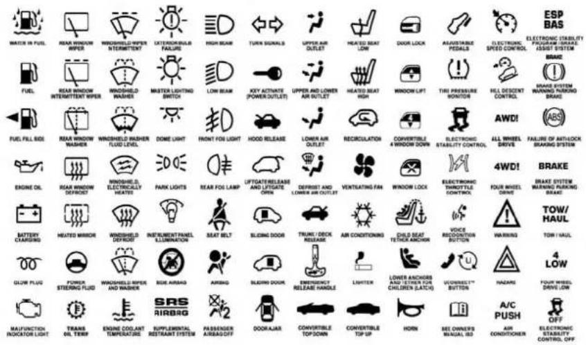
Symbols
Consult the following table for a description of the symbols that may be used on your vehicle or throughout this
Owner's Manual:
text_image
WATER IN FUEL REAR WINDOW WIPER WINDSHIELD WIPER INTERMETHET CATERBION INSULS FAILURES HIGH BEAR TURN SIGNALS UPPER AIR OUTLET HEATED BEAT LOW DOOR LOCK AVAILABLE PEDALS ELECTRONIC SPEED CONTROL ESP BAS ELECTRONIC STABILITY PROGRAM (BRATE ASSIST SYSTEM) BRAKE FUEL REAR WINDOW INTERMITTENT WIPER WINDSHIELD WASHER MASTER LIGHTING SWITCH LOW BEAR JOY ACTIVATE (POWER OUTLET) UPPER AND LOWER AIR OUTLET HEATED BEAT HIGH WINDOW LIPT THI PRESSURE MONITOR HELL DESCENT CONTROL BRAKE SYSTEM WARNING TURNING BRAKE FUEL FILL RIDI REAR WINDOW WASHER WINDSHIELD WASHER FLUID LEVEL DOME LIGHT FRONT FOI LIGHT HOOD RELEASE LOWER AIR OUTLET RECIRCULATION CONVERTIBLE 4 WINDOW DOWN ELECTRONIC STABILITY CONTROL AWDI ALL WHEEL DRIVE FAILURE OF ANTHON BREAKING SYSTEM BRAKE ENGINE OIL REAR WINDOW DEFROOD WINDSHIELD ELECTRICALLY HEATERS PARK LIGHTS REAR FOI LAMP LIFTGATERELEASE AND LIFTGATE OPEN DEFRUST AND LOWER AIR OUTLET VENTLEATING FAIR WINDOW LOCK ELECTRONIC THROTTLE CONTROL FOUR WHEEL DRIVE BATTERY CHARGING HEATED WIPER WINDSHIELD DEFROOD INSTRUMENT PANEL KILLAMINATION SEAT BELT SLICING DOOR TRUMI / DECK RELEASE AIR CONDITIONING CHILD SEAT TETRICK ANCHOR VOICE RECOCONITION BUTTON WARNING TOW/HAUL GLOW PLUG POWER STERING FLUID WINDSHIELD WIPER AND WASHER SIDE AIRSAG AIRSAG SLICING DOOR EMERGENCY RELEASE HANDLE LIGHTER LOWER ANCHORS AND LETTER FOR CHILDREN (LATCH) VONEEETTM BUTTON HAZARI FOUR WHEEL DRIVE LOW MALFUNCTION INDICATOR LIGHT TRANS OIL TERM ENGINE COOLANT TEMPERATING SRS AIRBAG SUPPLEMENTAL RESTRAINT SYSTEM PASSENGER AIRSAG OFF DOOR JAZAR CONVERTIBLE TOP DOWN CONVERTIBLE TOP UP HORN SEE OWNER'S MANUAL SO A/C PUSH AIR CONDITIONER OFF ELECTRONIC STABILITY CONTROL OFF010533317
WARNINGS AND CAUTIONS
This Owner's Manual contains WARNINGS against operating procedures that could result in a collision, bodily injury and/or death. It also contains CAUTIONS against procedures that could result in damage to your vehicle. If you do not read this entire Owner's Manual, you may miss important information. Observe all Warnings and Cautions.
VAN CONVERSIONS/CAMPERS
The New Vehicle Limited Warranty does not apply to body modifications or special equipment installed by van conversion/camper manufacturers/body builders. U.S. residents refer to the Warranty Information book, Section 2.1.C. Canadian residents refer to the "What Is Not Covered" section of the Warranty Information book. Such equipment includes video monitors, VCRs, heaters, stoves, refrigerators, etc. For warranty coverage and service on these items, contact the applicable manufacturer.
Operating instructions for the special equipment installed by the conversion/camper manufacturer should also be supplied with your vehicle. If these instructions are missing, please contact your authorized dealer for assistance in obtaining replacement documents from the applicable manufacturer.
For information on the Body Builder's Guide refer to www.rambodybuilder.com. This website contains dimensional and technical specifications for your vehicle. It is intended for Second Stage Manufacturer's technical support. For service issues, contact your authorized dealer.
VEHICLE MODIFICATIONS/ALTERATIONS
WARNING!
Anymodificationsoralterationstothisvehiclecould seriously affect its roadworthiness and safety and may leadtoacollisionresultinginseriousinjuryordeath.

GRAPHICAL TABLE OF CONTENTS
CONTENTS
■FRONT VIEW....10
■REAR VIEW....1 1
■INSTRUMENT PANEL....12
■INTERIOR....13
10 GRAPHICAL TABLE OF CONTENTS
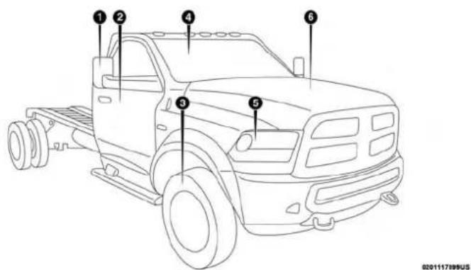
FRONT VIEW
text_image
Diagram of a 3D truck with numbered parts labeled for identificationFrontView
1 — Exterior Mirrors 4 — Windshield
2 — Doors 5 — Headlights
3 — Wheels/Tires 6 — Hood/Engine Compartment
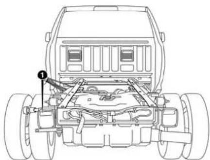
REAR VIEW
GRAPHICAL TABLE OF CONTENTS 11
natural_image
Technical line drawing of a vehicle chassis with labeled components (no text or symbols present)RearView
0201117900US
1 — Rear Lights

12 GRAPHICAL TABLE OF CONTENTS
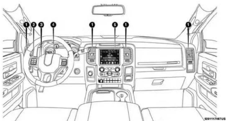
INSTRUMENT PANEL
text_image
Diagram of a car dashboard with numbered navigation keys and instrument panelsInstrumentPanel
1 — Air Vents 4 — Instrument Cluster
2 — Multifunction Lever 5 — Radio
3 — Steering Wheel
INTERIOR
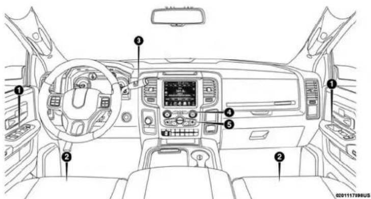
text_image
Diagram of a car dashboard with numbered components for identification and assembly reference.Interior
1 — Door Locks/Window Switches 4 — Switch Panel
2 — Seats 5 — Climate Controls
3 — Gear Selector

GETTING TO KNOW YOUR VEHICLE
CONTENTS
■KEYS....19
□Key Fobs....19
■IGNITION SWITCH....26
□Wireless Ignition Node (WIN) — If Equipped. . . . 2 6
☐Keyless Push Button Ignition — If Equipped . . . . 2 7
□Key-In-Ignition Reminder....28
■REMOTE START — IF EQUIPPED ..... 2 8
□How To Use Remote Start. 28
□Remote Start Abort Message....28
□To Enter Remote Start Mode....29
□To Exit Remote Start Mode Without Driving The Vehicle....29
□To Exit Remote Start Mode And Drive The Vehicle....29
□ Remote Start Comfort Systems — If Equipped . . .30
□ General Information ....30
■SENTRY KEY....30
□Customer Key Programming....3 1
□Replacement Keys....3 1
□ General Information ....32
■VEHICLE SECURITY ALARM....32
□To Arm The System....3 2
□To Disarm The System....3 3
□ Rearming Of The System .....33
□Security System Manual Override....34
■DOORS 34
□Manual Door Locks....3 4
□Power Door Locks — If Equipped . . . . . . . . . . 3 5
□ Keyless Enter-N-Go — Passive Entry .....36
16 GETTING TO KNOW YOUR VEHICLE
□Automatic Door Locks — If Equipped . . . . . . . 3 9
□Child-Protection Door Lock....40
■SEATS
□Manual Front Seat Adjustment....4 1
□Manual Rear Seat Adjustment....43
□Power Driver Seat Adjustment — If Equipped . . .44
□Power Passenger Seat Adjustment — If Equipped....4 6
□Driver Memory Seat — If Equipped . . . . . . . . . 4 6
□Heated Seats — If Equipped . . . . . . . . . . . . . . . . 5 0
□Ventilated Seats — If Equipped . . . . . . . . . . . . . . . 5 2
□Plastic Grocery Bag Retainers (Regular Cab Models) 53
■HEAD RESTRAINTS....53
□Front Head Restraint Adjustment....54
□ Rear Head Restraint Adjustment .....54
□Front Head Restraint Removal....5 5
□ Rear Head Restraint Removal .....55
■STEERING WHEEL....56
□ Tilt Steering Column .....56
□ Heated Steering Wheel — If Equipped. . . . . . . . .57
■DRIVER ADJUSTABLE PEDALS — IF EQUIPPED....57
■MIRRORS....59
□ Inside Day/Night Mirror — If Equipped .....59
□Automatic Dimming Mirror — If Equipped . . . . . 5 9
□Automatic Dimming Mirror With Rear View Camera Display — If Equipped . . . . . . . . . . . . . . 6 0
□Outside Mirrors....6 1
□Driver's Outside Automatic Dimming Mirror — If Equipped....6 1
□Power Mirrors — If Equipped . . . . . . . . . . . . . . 6 2
□Power Folding Outside Mirrors For Standard And Trailer Tow — If Equipped . . . . . . . . . . . . . . . . . . . . . . . . . 6 3
□ Trailer Towing Mirrors — If Equipped .....65
□ Heated Mirrors — If Equipped .....66
GETTING TO KNOW YOUR VEHICLE
17
□Tilt Side Mirrors In Reverse — If Equipped . . . . . 6 6
□Illuminated Vanity Mirror — If Equipped . . . . . 6 7
■EXTERIOR LIGHTS....68
□Headlight Switch....68
□Headlights....69
□Daytime Running Lights (DRL) — If Equipped . .69
□Multifunction Lever....6 9
□High/Low Beam Switch....70
□Automatic High Beam Headlamp Control — If Equipped....70
□Flash-To-Pass....71
□Automatic Headlights — If Equipped . . . . . . . . 7 1
□Parking Lights And Panel Lights. 72
□Headlights On With Wipers (Available With Automatic Headlights Only)....72
□Headlight Delay....72
□Lights-On Reminder. 72
□ Fog Lights — If Equipped .....73
□ Turn Signals .....73
□ Lane Change Assist — If Equipped .....74
□Cargo Light 74
□ Battery Saver....74
■INTERIOR LIGHTS....74
□ Courtesy Lights....74
□Illuminated Approach....77
■WINDSHIELD WIPERS AND WASHERS ..... 7 7
□Windshield Wipers....77
□Rain Sensing Wipers — If Equipped . . . . . . . . . 7 9
■CLIMATE CONTROLS....80
□Manual Climate Controls Without Touchscreen . .80
□Automatic Climate Controls With A Touchscreen....85
□Climate Control Functions....93
□Automatic Temperature Control (ATC) — If Equipped....94
□ Operating Tips .....95
18 GETTING TO KNOW YOUR VEHICLE
■WINDOWS....97
□Power Windows — If Equipped . . . . . . . . . . . . . 9 7
□Wind Buffeting....100
■HOOD....100
□To Open The Hood....100
□To Close The Hood. . . . . . . . . . . . . . . . . . . . . . . . . . . . . . . . . . . . . . . . . . . . 101
■GARAGE DOOR OPENER — IF EQUIPPED ....102
□Before You Begin Programming HomeLink . . . . .103
□Programming A Rolling Code....104
□Programming A Non-Rolling Code....105
□Canadian/Gate Operator Programming .....106
□Using HomeLink....108
□Security....108
□Troubleshooting Tips....108
□General Information....109
■INTERNAL EQUIPMENT....109
□Storage....109
□Cupholders .....121
□ Electrical Power Outlets .....122
□Cigar Lighter And Ash Receiver — If Equipped .....126
□Power Inverter — If Equipped .....126
□ Auxiliary Switches — If Equipped .....127
KEYS
Key Fobs
Your vehicle uses either a wireless ignition node system or keyless ignition system. The ignition system consists of a key fob with a Remote Keyless Entry (RKE) and an ignition switch. The keyless ignition system consists of a key fob and Keyless Enter-N-Go button.
NOTE: The key fob may not be found if it is located next to a mobile phone, laptop or other electronic device; these devices may block the key fob's wireless signal.
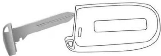
The key fob operates the ignition switch. Insert the square end of the key fob into the ignition switch located on the instrument panel and rotate to the desired position. It also contains the key fob and an emergency key, which stores in the rear of the key fob.
The emergency key allows for entry into the vehicle should the battery in the vehicle or the key fob go dead. You can keep the emergency key with you when valet parking.
To remove the emergency key, slide the mechanical latch at the top of the key fob sideways with your thumb and then pull the key out with your other hand.
NOTE: When using the emergency key to gain access to your vehicle, be aware that the security alarm may be triggered. Insert the key into the ignition and place the ignition in the ON/RUN mode to disarm the security system.
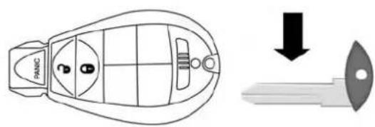
text_image
PANIC0301117793US
KeyFobEmergencyKey
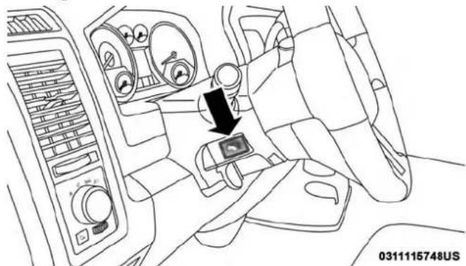
This Keyless Push Button Ignition key fob allows the driver to operate the ignition switch with the push of a button, as long as the key fob is in the passenger compartment. The Keyless Push Button Ignition has four operating positions, three of which are labeled and will illuminate when in position. The three positions are OFF, ACC, and ON/RUN.

20 GETTING TO KNOW YOUR VEHICLE
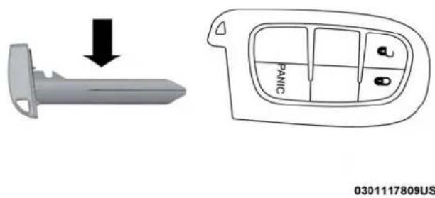
The fourth position is START, during start RUN will illuminate. It also contains the key fob and an emergency key, which stores in the rear of the key fob.
The emergency key allows for entry into the vehicle should the battery in the vehicle or the key fob go dead. You can keep the emergency key with you when valet parking.
To remove the emergency key, slide the mechanical latch on the backside of the key fob sideways with your thumb and then pull the key out with your other hand.
NOTE: When using the emergency key to gain access to your vehicle, be aware that the security alarm may be triggered. Put the nose side (side opposite of the emergency key) of the key fob against the ENGINE START/STOP button and push to disarm the security system.
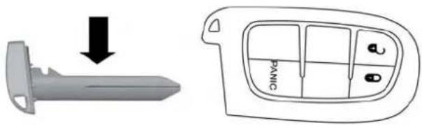
text_image
Diagram showing a gray tool with a downward arrow and a fan panel labeled 'PANIC' with control buttons.0301117809US
KeyFobEmergencyKey
NOTE: You can insert the double-sided emergency key into the door lock cylinder with either side up.
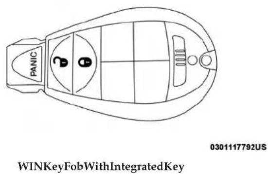
The Remote Keyless Entry system allows you to lock or unlock all doors, and the tailgate as well as activate the Panic Alarm from distances up to approximately 66 ft (20 m) using a key fob with integrated key. The key fob does not need to be pointed at the vehicle to activate the system. Push and release the lock button on the key fob to lock all doors, and the tailgate. The turn signal lights will flash and the horn will chirp to acknowledge the signal.

NOTE: Inserting the key fob with integrated key into the ignition switch disables the system from responding to any button pushes from that key fob. Driving at speeds 5 mph (8 km/h) and above disables the system from responding to all key fob buttons for all key fobs.
text_image
PANIC WINKeyFobWithIntegratedKey 0301117792US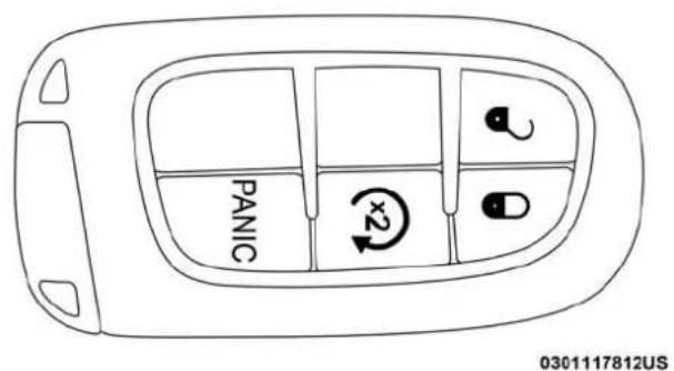
text_image
PANIC x2 0301117812USPassiveEntryKeyFob
ToUnlockTheDoorsAndTailgate
Push and release the unlock button on the key fob once to unlock the driver's door. Push the unlock button twice within five seconds to unlock all doors, and the tailgate. The turn signal lights will flash to acknowledge the unlock signal. The illuminated entry system will also turn on.
NOTE: The instrument cluster display or Uconnect Settings are setup for driver door first, otherwise this will unlock all doors.

22 GETTING TO KNOW YOUR VEHICLE
ToLockTheDoorsAndTailgate
Push and release the lock button on the key fob to lock all doors, and the tailgate. The turn signal lights will flash and the horn will chirp to acknowledge the signal.
SoundHornWithLock
This feature will cause the horn to chirp when the doors are locked with the key fob. This feature can be turned on or turned off. To change the current setting, proceed as follows:
- For vehicles not equipped with a touchscreen radio, refer to "Instrument Cluster Display" in "Getting To Know Your Instrument Panel" for further information.
- For vehicles equipped with a touchscreen radio, refer to "Uconnect Settings" in "Multimedia" for further information.
NOTE: Pushing the lock button on the key fob while you are in the vehicle will activate the vehicle security alarm system. Opening a door with the vehicle security alarm system activated will cause the alarm to sound. Push the unlock button to deactivate the vehicle security alarm system.
UsingThePanicAlarm
To turn the Panic Alarm feature on or off, push the Panic button on the key fob. When the Panic Alarm is activated, the turn signals will flash, the horn will pulse on and off, and the interior lights will turn on.
The Panic Alarm will stay on for three minutes unless you turn it off by either pushing the Panic button a second time or drive the vehicle at a speed of 15 mph (24 km/h) or greater.
NOTE:
- The interior lights will turn off if you place the ignition in the ACC or ON/RUN position while the Panic Alarm is activated. However, the exterior lights and horn will remain on.
- You may need to be less than 35 ft (11 m) from the vehicle when using the key fob to turn off the Panic Alarm due to the radio frequency noises emitted by the system.
ReplacingTheBatteryInTheKeyFobWithRemote Control
The recommended replacement battery is one CR2032 battery.
NOTE:
- Perchlorate Material — special handling may apply. See www.dtsc.ca.gov/hazardouswaste/perchlorate for further information.
-
Do not touch the battery terminals that are on the back housing or the printed circuit board.
-
Remove the emergency key by sliding the mechanical latch on the back of the key fob sideways with your thumb and then pull the key out with your other hand.

text_image
PANC0301117793US
EmergencyKeyRemoval
24 GETTING TO KNOW YOUR VEHICLE
text_image
PANIC 0301117809USEmergencyKeyRemoval
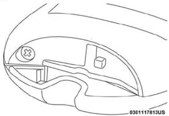
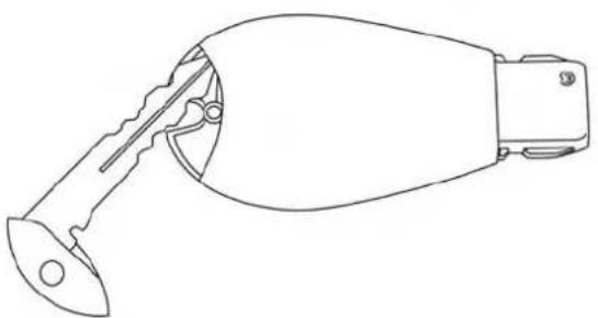
- Separating key fob halves requires screw removal – if equipped, and gently prying the two halves of the key fob apart. Make sure not to damage the seal during removal.
natural_image
Technical line drawing of a mechanical component or bracket (no text or symbols)RemoveScrewFromKeyFobCase

natural_image
Line drawing of a handheld device with a pointed tip and handle (no text or symbols)0301117795US
natural_image
Line drawing of a car key and its open hood (no text or symbols)0301101915NA
SeparatingKeyFobCaseSeparatingKeyFobCase
- Remove the battery by turning the back cover over (battery facing downward) and tapping it lightly on a solid surface such as a table or similar, then replace the battery. When replacing the battery, match the + sign on the battery to the + sign on the inside of the battery clip, located on the back cover. Avoid touching the new battery with your fingers. Skin oils may cause battery deterioration. If you touch a battery, clean it with rubbing alcohol.
- To assemble the key fob case, snap the two halves together, reposition and secure the screw as shown in step #2 for removal.

26 GETTING TO KNOW YOUR VEHICLE
ProgrammingAdditionalKeyFobs
Programming the key fob may be performed by an authorized dealer.
GeneralInformation
The following regulatory statement applies to all radio frequency (RF) devices equipped in this vehicle:
This device complies with Part 15 of the FCC Rules and with Industry Canada license-exempt RSS standard(s). Operation is subject to the following two conditions:
- This device may not cause harmful interference, and
- This device must accept any interference received, including interference that may cause undesired operation.
NOTE: Changes or modifications not expressly approved by the party responsible for compliance could void the user's authority to operate the equipment.
IGNITION SWITCH
Wireless Ignition Node (WIN) — If Equipped
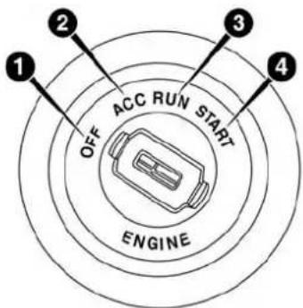
The Wireless Ignition Node (WIN) operates similar to an ignition switch. It has four operating positions, three with detents and one that is spring-loaded. The detent positions are OFF, ACC, and ON/RUN. The START position is a spring-loaded momentary contact position. When released from the START position, the switch automatically returns to the ON/RUN position.
text_image
1 2 OFF ACC RUN START 3 4 ENGINE0301127600US
WirelessIgnitionSwitch
1-OFF
2 — ACC (Accessory)
3—ON/RUN
4 — START

Keyless Push Button Ignition — If Equipped
This feature allows the driver to operate the ignition switch with the push of a button as long as the Remote Keyless Entry key fob is in the passenger compartment.
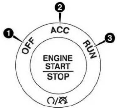
The Keyless Push Button Ignition has four operating positions; three of which are labeled and will illuminate when in position. The three positions are OFF, ACC, and ON/RUN. The fourth position is START, during start RUN will illuminate.
NOTE: In case the ignition switch does not change with the push of a button, the key fob may have a low or dead battery. In this situation, a back up method can be used to operate the ignition switch. Put the nose side (side opposite of the emergency key) of the key fob against the ENGINE START/STOP button, with your foot applied on the brake pedal, and push to operate the ignition switch.
flowchart
graph TD
    A["1 OFF"] --> B["2 ACC"]
    B --> C["3 RUN"]
    C --> D["4 STOP"]
    style A fill:#f9f,stroke:#333
    style B fill:#ccf,stroke:#333
    style C fill:#cfc,stroke:#333
    style D fill:#fcc,stroke:#333
0301113478US
KeylessPushButtonIgnition
1-OFF
2 — ACC (Accessory)
3—ON/RUN
28 GETTING TO KNOW YOUR VEHICLE
Key-In-Ignition Reminder
Opening the driver's door when the key fob is in the ignition and the ignition switch position is OFF or ACC, a chime will sound to remind you to remove the key fob.
NOTE:
- "Keyed" Ignition systems will chime in OFF or ACC when the driver door is open.
- "Keyless"Ignition systems will chime in ACC or RUN when the driver door is open.
- The instrument cluster display will display "Key In Ignition."
REMOTE START — IF EQUIPPED
How To Use Remote Start
All of the following conditions must be met before the engine will remote start:
•Gear selector in PARK
- Doors closed
- Hood closed
•HAZARD switch off
- BRAKE switch inactive (brake pedal not pushed
- Ignition key removed from ignition switch
- Battery at an acceptable charge level
- PANIC button not pushed
• Fuel meets minimum requirement - System not disabled from previous remote start event
• Vehicle security alarm not active
WARNING!
- Donotstartorrunanengineinaclosedgarageor confinedarea.ExhaustgascontainsCarbonMonoxide(CO)whichisodorlessandcolorless.Carbon Monoxideispoisonousandcancauseseriousinjury ordeathwheninhaled.
- Keepkeyfobsawayfromchildren.Operationofthe RemoteStartSystem,windows,doorlocksorother controlscouldcauseseriousinjuryordeath.
Remote Start Abort Message
The following messages will display in the instrument cluster display if the vehicle fails to remote start or exits remote start prematurely:
• Remote Start Cancelled — Door Open

GETTING TO KNOW YOUR VEHICLE 29
- Remote Start Cancelled — Hood Open
- Remote Start Cancelled — Fuel Low
- Remote Start Cancelled — System Fault
- Remote Start Disabled — Start Vehicle to Reset
The instrument cluster display message stays active until the ignition is turned to the ON/RUN position.
To Enter Remote Start Mode
Push and release the Remote Start button on the key fob twice within five seconds. The parking lights will flash, vehicle doors will lock, and the horn will chirp twice (if programmed). Once the vehicle has started, the engine will run for 15 minutes.
NOTE:
- If your power door locks were unlocked, Remote Start will automatically lock the doors.
- If an engine fault is present or fuel level is low, the vehicle will start and then shut down in 10 seconds.
-
The park lamps will turn on and remain on during Remote Start mode.
-
For security, power window and power sunroof operation (if equipped) are disabled when the vehicle is in the Remote Start mode.
- The engine can be started two consecutive times (two 15-minute cycles) with the key fob. However, the ignition must be placed in the ON/RUN position before you can repeat the start sequence for a third cycle.
To Exit Remote Start Mode Without Driving The Vehicle
Push and release the remote start button one time or allow the engine to run for the entire 15-minute cycle.
NOTE: To avoid unintentional shutdowns, the system will disable with a one time push of the remote start button for two seconds after receiving a valid remote start request.
To Exit Remote Start Mode And Drive The Vehicle
Before the end of the 15-minute cycle, push and release the unlock button on the key fob to unlock the doors and disarm the vehicle security alarm system (if equipped). Then, prior to the end of the 15-minute cycle, cycle the ignition to the ON/RUN position.

30 GETTING TO KNOW YOUR VEHICLE
Remote Start Comfort Systems — If Equipped
When Remote Start is activated, the heated steering wheel and driver heated seat features will automatically turn on in cold weather. In warm weather, the driver vented seat feature will automatically turn on when the remote start is activated. These features will stay on through the duration of Remote Start or until the ignition switch is placed in the ON/RUN mode.
NOTE: The Remote Start Comfort System can be activated and deactivated through the Uconnect System. Refer to "Uconnect Settings" in "Multimedia" for further information on Remote Start Comfort System operation.
General Information
The following regulatory statement applies to all radio frequency (RF) devices equipped in this vehicle:
This device complies with Part 15 of the FCC Rules and with Industry Canada license-exempt RSS standard(s). Operation is subject to the following two conditions:
- This device may not cause harmful interference, and
- This device must accept any interference received, including interference that may cause undesired operation.
NOTE: Changes or modifications not expressly approved by the party responsible for compliance could void the user's authority to operate the equipment.
SENTRY KEY
The Sentry Key Immobilizer System prevents unauthorized vehicle operation by disabling the engine. The system does not need to be armed or activated. Operation is automatic, regardless of whether the vehicle is locked or unlocked.
The system uses a key fob, an Ignition Node Module, Keyless Push Button Ignition and a RF receiver to prevent unauthorized vehicle operation. Therefore, only key fobs that are programmed to the vehicle can be used to start and operate the vehicle. The system will not allow the engine to crank if an invalid key fob is used to start and operate the vehicle. The system will shut the engine off in two seconds if an invalid key fob is used to start the engine.
NOTE:A key fob that has not been programmed is also considered an invalid key.
During normal operation, after placing the keyless ignition in the ON/RUN position, the vehicle security light will turn on for three seconds for a bulb check. If the light remains on after the bulb check, it indicates that there is a

problem with the electronics. In addition, if the light begins to flash after the bulb check, it indicates that someone used an invalid key fob to try to start the engine. Either of these conditions will result in the engine being shut off after two seconds.
If the vehicle security light turns on during normal vehicle operation (vehicle running for longer than 10 seconds), it indicates that there is a fault in the electronics. Should this occur, have the vehicle serviced as soon as possible by an authorized dealer.
CAUTION!
The SentryKeyImmobilizersystemisnotcompatible with some aftermarketremotestartingsystems.Useof thesesystemsmayresultinvehiclestartingproblems andlossofsecurityprotection.
All of the key fobs provided with your new vehicle have been programmed to the vehicle electronics.
Customer Key Programming
Programming key fobs may be performed at an authorized dealer.
Replacement Keys
NOTE: Only key fobs that are programmed to the vehicle electronics can be used to start and operate the vehicle. Once a key fob is programmed to a vehicle, it cannot be programmed to any other vehicle.
CAUTION!
- Alwaysremovethekeyfobsfromthevehicleand lockalldoorswhenleavingthevehicleunattended.
- ForvehiclesequippedwithKeylessEnter-N-Go—Ignition,alwaysremembertoplacetheignitionin theOFFposition.
NOTE: Duplication of key fobs may be performed at an authorized dealer. This procedure consists of programming a blank key fob to the vehicle electronics. A blank key fob is one that has never been programmed.
When having the Sentry Key Immobilizer System serviced, bring all vehicle keys with you to an authorized dealer.
32 GETTING TO KNOW YOUR VEHICLE
General Information
The following regulatory statement applies to all radio frequency (RF) devices equipped in this vehicle:
This device complies with Part 15 of the FCC Rules and with Industry Canada license-exempt RSS standard(s). Operation is subject to the following two conditions:
- This device may not cause harmful interference, and
- This device must accept any interference received, including interference that may cause undesired operation.
NOTE: Changes or modifications not expressly approved by the party responsible for compliance could void the user's authority to operate the equipment.
VEHICLE SECURITY ALARM
The vehicle security alarm monitors the vehicle doors and ignition for unauthorized operation. When the vehicle security alarm is activated, interior switches for door locks are disabled. The system provides both audible and visible signals for the first three minutes. The horn will sound, the headlights will turn on, the park lamps and/or turn signals will flash and vehicle security light will flash repeatedly. For an additional 15 minutes only, the headlights will turn on, the park lamps and/or turn signals, and vehicle security light will flash.
To Arm The System
Follow these steps to arm the vehicle security alarm:
-
Remove the key from the ignition system (refer to "Starting The Engine" in "Starting And Operating" for further information).
-
For vehicles equipped with Keyless Enter-N-Go — Ignition, make sure the vehicle ignition system is "OFF."
-
For vehicles not equipped with Keyless Enter-N-Go — Ignition, make sure the vehicle ignition system is "OFF" and the key is physically removed from the ignition.
-
Perform one of the following methods to lock the vehicle:
-
Push lock button on the interior power door lock switch with the driver and/or passenger door open.
- Push the lock button on the exterior Passive Entry Door Handle with a valid key fob available in the same exterior zone (refer to "Keyless Enter- N-Go — Passive Entry" in "Getting To Know Your Vehicle" for further information).
- Push the lock button on the key fob.

- If any doors are open, close them.
The vehicle security alarm will set when you use the power door locks, or use the key fob to lock the doors. After all the doors are locked and closed, the vehicle security light, in the instrument panel cluster, will flash rapidly for about 16 seconds to indicate that the alarm is being set. After the alarm is set, the vehicle security light will flash at a slower rate to indicate that the system is armed.
To Disarm The System
The vehicle security alarm can be disarmed using any of the following methods:
- Push the unlock button on the key fob.
- Grasp the Passive Entry Unlock Door Handle with a valid key fob within 5 ft (1.5 m) of the passive entry door handle. If equipped, refer to "Keyless Enter-N-Go — Passive Entry" in "Getting To Know Your Vehicle" for further information.
- Cycle the ignition out of the OFF position.
- For vehicles equipped with Keyless Enter-N-Go — Ignition, push the Keyless Ignition START/STOP button (requires at least one valid key fob in the vehicle).
- For vehicles not equipped with Keyless Enter-N-Go, insert a valid key into the ignition switch and turn the key to the ON position.
The vehicle security alarm is designed to protect your vehicle. However, you can create conditions where the system will give you a false alarm. If one of the previously described arming sequences has occurred, the vehicle security alarm will arm regardless of whether you are in the vehicle or not. If you remain in the vehicle and open a door, the alarm will sound. If this occurs, disarm the vehicle security alarm.
If the vehicle security alarm is armed and the battery becomes disconnected, the vehicle security alarm will remain armed when the battery is reconnected; the exterior lights will flash, and the horn will sound. If this occurs, disarm the vehicle security alarm.
Rearming Of The System
The vehicle security alarm will rearm itself after the 15 additional minutes of headlights and vehicle security light flashing, if the system has not been disabled. If the condition which initiated the alarm is still present, the system will ignore that condition and monitor the remaining doors and ignition.

34 GETTING TO KNOW YOUR VEHICLE
Security System Manual Override
The vehicle security alarm will not arm if you lock the doors using the manual door lock plunger.
DOORS
Manual Door Locks
Front and rear doors may be locked by moving the lock knob down or unlocked by moving the lock knob up.

natural_image
Line drawing of a car interior showing the dashboard and seat area (no text or symbols)DoorLockKnob
Front doors may be opened with the inside door handle without lifting the lock knob.
Doors locked before closing will remain locked when closed.
The emergency key will unlock the driver door lock on your vehicle.
WARNING!
- Donotleavechildrenoranimalsinsideparked vehiclesinhotweather.Interiorheatbuild-upmay causeseriousinjuryordeath.
- Forpersonalsecurityandsafetyintheeventofan collision,lockthevehicledoorsasyoudriveaswell aswhenyouparkandleavethevehicle.
- Beforeexitingvehicle, alwaysshifttheautomatic transmission into PARKorthemanualtransmission into FIRST gearor REVERSE, apply the parking brake, turn the vehicle OFF, removethe key fobs from vehicle, and lock all doors. and lock your vehicle.
- Neverleavechildrenaloneinavehicle,orwithaccess toanunlockedvehicle.Leavingchildreninavehicle unattendedisdangerousforanumberofreasons.A childorotherscouldbeseriouslyorfatallyinjured. Childrenshouldbewarnednottotouchtheparking brake,brakepedalorthegearselector.
WARNING!(Continued)
- Allowingchildrentobeinavehicleunattendedis dangerousforanumberofreasons.Achildorothers couldbeseriouslyorfatallyinjured.Children shouldbewarnednottotouchtheparkingbrake, brakepedalorthegearselector.
- Donotleavethekeyfobinornearthevehicle,orinalocationaccessibletochildren,anddonotleavetheignitionofavehicleequippedwithKeylessEnter-N-GointheACCorON/RUNmode.Achildcouldoperatepowerwindows,othercontrols,ormovethevehicle.
Power Door Locks — If Equipped
The power door lock switches are on each front door trim panel. Use these switches to lock or unlock the doors.
NOTE: The key fob may not be able to be detected by the vehicle Keyless Enter-N-Go system if it is located next to a mobile phone, laptop or other electronic device; these devices may block the key fob's wireless signal and prevent the Keyless Enter-N-Go system from starting the vehicle.

text_image
PowerDoorLockSwitch 0301117797USIf you push the power door lock switch while the key fob is in the ignition, and any front door is open, the power locks will not operate. This prevents you from accidentally locking your key fob in the vehicle. Removing the key fob or closing the door will allow the locks to operate. A chime will sound if the key fob is in the ignition switch and a door is open, as a reminder to remove the key fob.
36 GETTING TO KNOW YOUR VEHICLE
Keyless Enter-N-Go — Passive Entry
The Passive Entry system is an enhancement to the vehicle's Remote Keyless Entry system and a feature of Keyless Enter-N-Go. This feature allows you to lock and unlock the vehicle's door(s) without having to push the key fob lock or unlock buttons.
NOTE:
- Passive Entry may be programmed ON/OFF. Refer to "Uconnect Settings" in "Multimedia" for further information.
- If wearing gloves on your hands, or if it has been raining/snowing on the Passive Entry door handle, the unlock sensitivity can be affected, resulting in a slower response time.
- If the vehicle is unlocked by Passive Entry and no door is opened within 60 seconds, the vehicle will re-lock and if equipped will arm the security alarm.
- The vehicles security alarm can be armed/disarmed by pushing the passive entry key fob lock/unlock buttons (if equipped).
- The key fob may not be able to be detected by the vehicle passive entry system if it is located next to a mobile phone, laptop or other electronic device; these devices may block the key fob's wireless signal and prevent the passive entry handle from locking/unlocking the vehicle.
ToUnlockFromTheDriver'sSide:
With a valid Passive Entry key fob within 5 ft (1.5 m) of the driver door handle, grab the front driver door handle to unlock the driver's door automatically. The interior door panel lock knob will raise when the door is unlocked.

natural_image
Hand holding a remote control device with a button, no visible text or symbols on the device itselfGrabTheDoorHandleToUnlock

NOTE: If "Unlock All Doors 1st Press" is programmed, all doors will unlock when you grab hold of the front driver's door handle. To select between "Unlock Driver Door 1st Press" and "Unlock All Doors 1st Press," refer to "Uconnect Settings" in "Multimedia" for further information.
ToUnlockFromThePassengerSide:
With a valid Passive Entry key fob within 5 ft (1.5 m) of the passenger door handle, grab the front passenger door handle to unlock all doors automatically. The interior door panel lock knob will raise when the door is unlocked.
NOTE: All doors will unlock when the front passenger door handle is grabbed regardless of the driver's door unlock preference setting ("Unlock Driver Door 1st Press" or "Unlock All Doors 1st Press").
PreventingInadvertentLockingOfPassiveEntryKey FobInVehicle:
To minimize the possibility of unintentionally locking a Passive Entry key fob inside your vehicle, the Passive Entry system is equipped with an automatic door unlock feature which will function if the ignition switch is in the OFF position.
If one of the vehicle doors is open and the door panel switch is used to lock the vehicle, once all open doors have been closed the vehicle checks the inside and outside of the vehicle for any valid Passive Entry key fobs. If one of the vehicle's Passive Entry key fobs is detected inside the vehicle, and no other valid Passive Entry key fobs are detected outside the vehicle, the Passive Entry System automatically unlocks all vehicle doors and chirps the horn three times (on the third attempt ALL doors will lock and the Passive Entry key fob can be locked in the vehicle).
38 GETTING TO KNOW YOUR VEHICLE
ToLockTheVehicle'sDoors:
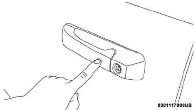
With one of the vehicle's Passive Entry key fobs within 5 ft (1.5 m) of the driver or passenger front door handles, push the door handle lock button to lock all doors.
natural_image
Line drawing of a hand holding a small mechanical component, no text or symbols presentPushTheDoorHandleButtonToLock
Do NOT grab the door handle when pushing the door handle lock button. This could unlock the door(s).
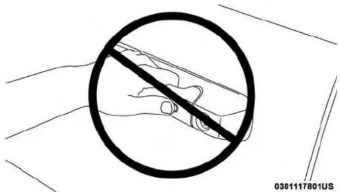
text_image
0301117801USDoNOTGrabTheDoorHandleWhenLocking
NOTE:
• After pushing the door handle lock button, you must wait two seconds before you can lock or unlock the doors, using either Passive Entry door handle. This is done to allow you to check if the vehicle is locked by pulling the door handle, without the vehicle reacting and unlocking.
- The Passive Entry system will not operate if the key fob battery is dead.

The vehicle doors can also be locked by using the key fob lock button or the lock button located on the vehicle's interior door panel.
GeneralInformation
The following regulatory statement applies to all radio frequency (RF) devices equipped in this vehicle:
This device complies with Part 15 of the FCC Rules and with Industry Canada license-exempt RSS standard(s). Operation is subject to the following two conditions:
- This device may not cause harmful interference, and
- This device must accept any interference received, including interference that may cause undesired operation.
NOTE: Changes or modifications not expressly approved by the party responsible for compliance could void the user's authority to operate the equipment.
Automatic Door Locks — If Equipped
The auto door lock feature default condition is enabled. When enabled, the door locks will lock automatically when the vehicle's speed exceeds 15 mph (24 km/h). The auto door lock feature can be enabled or disabled by an authorized dealer per written request of the customer. Please see an authorized dealer for service.
AutomaticDoorsUnlock—IfEquipped
This feature unlocks all of the doors of the vehicle when either front door is opened. This will occur only after the vehicle has been shifted into the PARK position after the vehicle has been driven (shifted out of PARK and all doors closed).
AutomaticDoorsUnlockProgramming—If Equipped
The Automatic Doors Unlock feature can be enabled or disabled as follows:
- For vehicles not equipped with a touchscreen radio, refer to "Instrument Cluster Display" in "Getting To Know Your Instrument Panel" for further information.
- For vehicles equipped with a touchscreen radio, refer to "Uconnect Settings" in "Multimedia" for further information.
NOTE: Use the Auto Unlock Doors feature in accordance with local laws.

40 GETTING TO KNOW YOUR VEHICLE
Child-Protection Door Lock
To provide a safer environment for children riding in the rear seat, the rear doors (if equipped) of your vehicle have the Child-Protection Door Lock system.
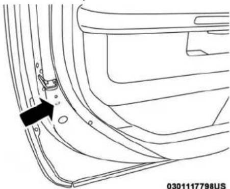
natural_image
Technical line drawing of a car door panel with a black arrow pointing to a small component (no text or symbols present)Child-ProtectionDoorLockLocation
To use the system, open each rear door, use a flat blade screwdriver (or emergency key) and rotate the dial to engage and disengage the Child-Protection locks. When the system on a door is engaged, that door can only be opened by using the outside door handle even if the inside door lock is in the unlocked position.

text_image
ChildLockControl 0305128931USWARNING!
Avoidtrappinganyoneinvehicleinacollision. Rememberthatthereardoorscanonlybeopenedfrom theoutsidewiththeChild-Protectionlocksareengaged(locked).
NOTE:
- After setting the Child-Protection Door Lock system, always test the door from the inside to make certain it is in the desired position.
- For emergency exit with the system engaged, move the door lock switch to the unlock position, roll down the window and open the door with the outside door handle.
SEATS
Seats are a part of the Occupant Restraint System of the vehicle.
WARNING!
- Itisdangeroustorideinacargoarea,insideoroutside ofvehicle.Inacollision,peopleridingintheseareas aremorelikelytobeseriouslyinjuredorkilled.
- Donotallowpeopletorideinanyareaofyour vehiclethatisnotequippedwithseatsandseatbelts. Inacollision,peopleridingintheseareasaremore likelytobeseriouslyinjuredorkilled.
- Besureeveryoneinyourvehicleisinaseatand usingaseatbeltproperly.
Manual Front Seat Adjustment
ManualFrontSeatForward/RearwardAdjustment
Both front seats are adjustable forward or rearward. The manual seat adjustment handle is located under the seat cushion at the front edge of each seat.
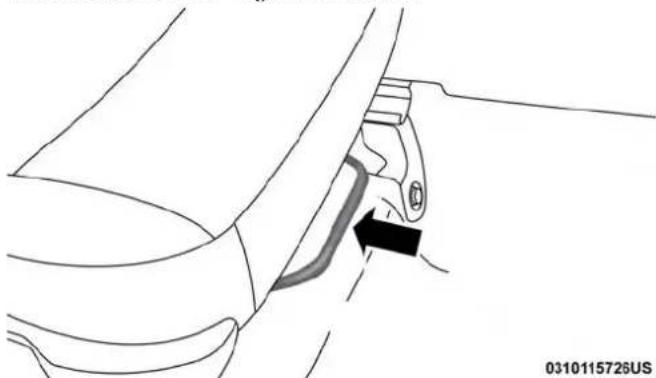
natural_image
Diagram of a mechanical component with a highlighted section and arrow, no readable text or symbols presentManualSeatAdjuster
While sitting in the seat, pull up on the handle and slide the seat forward or rearward. Release the bar once you have reached the desired position. Then, using body pressure, move forward and rearward on the seat to be sure that the seat adjusters have latched.

WARNING!
- Adjustingaseatwhiledrivingmaybedangerous. Movingaseatwhiledrivingcouldresultinlossof controlwhichcouldcauseacollisionandserious injuryordeath.
- Seatsshouldbeadjustedbeforefasteningtheseat beltsandwhilethevehicleisparked.Seriousinjury ordeathcouldresultfromapoorlyadjustedseatbelt.
ManualFrontSeatReclineAdjustment
The recline lever is located on the outboard side of the seat. To recline the seat, lean forward slightly, lift the lever, lean back to the desired position and release the lever. To return the seatback to its normal upright position, lean forward and lift the lever. Release the lever once the seat back is in the upright position
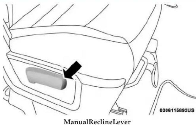
text_image
ManualReclineLever 0306115892USWARNING!
- Donotstandorleaninfrontoftheseatwhile actuatingthehandle.Theseatbackmayswingforwardandhityoucausinginjury.
• To avoid injury, place your hand on these seat back and actuat the handle, then position these seat back in the desired position.
GETTING TO KNOW YOUR VEHICLE 43
40-20-40FrontBenchSeat—IfEquipped
The seat is divided into three segments. The outboard seat portions are each 40% of the total width of the seat. On some models, the back of the center portion (20%) easily folds down to provide an armrest/center storage compartment.
Manual Rear Seat Adjustment
RecliningRearSeats—IfEquipped
The recliner handle is located on the outside of the seat cushion. To adjust the seatback, lift upward on the handle, lean back on the seatback and when you reach the desired position, release the handle.
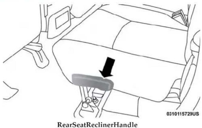
text_image
RearSeatReclinerHandle 0310115729USWARNING!
Donotridewiththeseatbackreclinedsothatthe shoulderbeltisnolongerrestingagainstyourchest.In acollisionyoucouldslideundertheseatbelt,which couldresultinseriousinjuryordeath.
44 GETTING TO KNOW YOUR VEHICLE
Power Driver Seat Adjustment — If Equipped
Some models may be equipped with an eight-way power driver's seat. The power seat switches are located on the outboard side of the driver's seat cushion. There are two power seat switches that are used to control the movement of the seat cushion and the seatback.
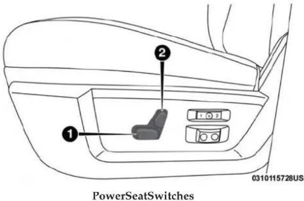
text_image
PowerSeatSwitches 0310115728US1 — Power Seat Switch
2 — Power Seatback Switch
AdjustingTheSeatForwardOrRearward
The seat can be adjusted both forward and rearward. Push the seat switch forward or rearward. The seat will move in the direction of the switch. Release the switch when the desired position has been reached.
AdjustingTheSeatUpUpDown
The height of the seats can be adjusted up or down. Pull upward or push downward on the rear of seat switch, the seat will move in the direction of the switch. Release the switch when the desired position has been reached.
TiltingTheSeatUpUpDown
The angle of the seat cushion can be adjusted in four directions. Pull upward or push downward on the front or rear of the seat switch, the front or rear of the seat cushion will move in the direction of the switch. Release the switch when the desired position is reached.
RecliningTheSeatback
The angle of the seatback can be adjusted forward or rearward. Push the seatback switch forward or rearward, the seat will move in the direction of the switch. Release the switch when the desired position is reached.

WARNING!
- Adjustingaseatwhiledrivingmaybedangerous. Movingaseatwhiledrivingcouldresultinlossof controlwhichcouldcauseacollisionandserious injuryordeath.
- Seatsshouldbeadjustedbeforefasteningtheseat beltsandwhilethevehicleisparked.Seriousinjury ordeathcouldresultfromapoorlyadjustedseatbelt.
- Donotridewiththeseatbackreclinedsothatthe shoulderbeltisnolongerrestingagainstyourchest. Inacollisionyoucouldslideundertheseatbelt, whichcouldresultinseriousinjuryordeath.
CAUTION!
Donotplaceanyarticleunderapowerseatorimpede itsabilitytomoveasitmaycausedamagetotheseat controls.Seattravelmaybecomelimitedifmovement isstoppedbyanobstructionintheseat'spath.
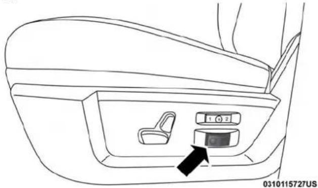
PowerLumbar—IfEquipped
Vehicles equipped with power driver or passenger seats may be also be equipped with power lumbar. The power lumbar switch is located on the outboard side of the power seat. Push the switch forward to increase the lumbar support. Push the switch rearward to decrease the lumbar support.
natural_image
Line drawing of a car interior showing seatbelt and control panel (no text or symbols)LumbarControlSwitch
Power Passenger Seat Adjustment — If Equipped
Some models are equipped with a six-way power passenger seat. The power seat switch is located on the outboard side of the seat. The switch is used to control the movement of the seat and seat cushion.
AdjustingTheSeatForwardOrRearward
The seat can be adjusted both forward and rearward. Push the seat switch forward or rearward. The seat will move in the direction of the switch. Release the switch when the desired position has been reached.
AdjustingTheSeatUpUpDown
The height of the seats can be adjusted up or down. Pull upward or push downward on the rear of seat switch, the seat will move in the direction of the switch. Release the switch when the desired position has been reached.
TiltingTheSeatUpUpDown
The angle of the seat cushion can be adjusted in four directions. Pull upward or push downward on the front or rear of the seat switch, the front or rear of the seat cushion will move in the direction of the switch. Release the switch when the desired position is reached.
Driver Memory Seat — If Equipped
This feature allows the driver to store up to two different memory profiles for easy recall through a memory switch. Each memory profile contains desired position settings for the driver's seat, side mirrors, adjustable pedals (if equipped) and a set of desired radio station presets. Your remote keyless entry key fob can also be programmed to recall the same positions when the unlock button is pushed.
NOTE: Your vehicle is equipped with two key fobs, one key fob can be linked to memory position 1 and the other key fob can be linked to memory position 2.

GETTING TO KNOW YOUR VEHICLE 47
The memory seat buttons are located on the outboard side of the driver's seat cushion.

text_image
MemorySeatButtons 0310115730USProgrammingTheMemoryFeature
To create a new memory profile, perform the following:
-
Cycle the vehicle's ignition to the ON/RUN position (do not start the engine).
-
Adjust all memory profile settings to desired preferences (i.e., driver's seat, outside mirrors and radio station presets).
-
Push and release the set (S) button on the memory switch.
-
Within five seconds, push and release either of the memory buttons (1) or (2). The instrument cluster display will show which memory position has been set.
NOTE:
- Memory profiles can be set without the vehicle in PARK, but the vehicle must be in PARK to recall a memory profile.
- To set a memory profile to your key fob, refer to "Linking And Unlinking The Remote Keyless Entry Key Fob To Memory" in this section.
48 GETTING TO KNOW YOUR VEHICLE
LinkingAndUnlinkingTheRemoteKeylessEntry KeyFobToMemory
Your key fobs can be programmed to recall one of two pre-programmed memory profiles by pushing the unlock button on the key fob.
NOTE: Before programming your key fobs to memory the feature has to be selected.
- If your vehicle is equipped with a touchscreen, you must select the "Memory Linked To Fob" feature through the Uconnect system. Refer to "Uconnect Settings" in "Multimedia" for further information.
- If your vehicle is not equipped with a touchscreen, you must select the "Key Fob Linked To Memory" feature through the instrument cluster display. Refer to "Instrument Cluster Display" in "Getting To Know Your Instrument Panel" for further information.
To program your key fobs, perform the following:
- Cycle the vehicle's ignition to the OFF position.
- Select desired memory profile (1) or (2).
NOTE: If a memory profile has not already been set, refer to "Programming The Memory Feature" for instructions on how to set a memory profile.
- Once the profile has been recalled, push and release the set (S) button on the memory switch, then push and release button (1) or (2) accordingly. "Memory Profile Set" (1 or 2) will display in the instrument cluster display.
- Push and release the lock button on the key fob within 10 seconds.
NOTE: Your key fobs can be unlinked to your memory settings by pushing the set (S) button, and within 10 seconds, followed by pushing the unlock button on the key fob.
MemoryPositionRecall
NOTE:
- For vehicles equipped with an automatic transmission, the vehicle speed must be lower than 5 mph (8 km/h) to recall memory positions. If a recall is attempted when the vehicle speed is greater than 5 mph (8 km/h), a message will be displayed in the instrument cluster display.
- For vehicles equipped with a manual transmission, the vehicle speed must be at 0 mph (0 km/h) to recall memory positions. If a recall is attempted with the vehicle speed above 0 mph (0 km/h), a message will appear in the instrument cluster display.
DriverOneMemoryPositionRecall
- To recall the memory settings for driver one using the memory switch, push memory button (1) on the memory switch.
- To recall the memory settings for driver one using the key fob, push the unlock button on the key fob linked to memory position 1.
DriverTwoMemoryPositionRecall
- To recall the memory setting for driver two using the memory switch, push memory button (2) on the memory switch.
- To recall the memory settings for driver two using the key fob, push the unlock button on the key fob linked to memory position 2.
A recall can be cancelled by pushing any of the memory buttons during a recall (S, 1, or 2). When a recall is cancelled, the driver's seat and the power pedals (if equipped) stop moving. A delay of one second will occur before another recall can be selected.
EasyEntry/ExitSeat
This feature provides automatic driver's seat positioning to enhance driver mobility when entering and exiting the vehicle.
The distance the driver's seat moves depends on where you have the driver's seat positioned when you remove the key fob from the ignition (or change the ignition to OFF, for vehicles equipped with Keyless Enter-N-Go).
- When you remove the key fob from the ignition (or change the ignition to OFF, for vehicles equipped with Keyless Enter-N-Go), the driver's seat will move about 2.4 inches (60 mm) rearward if the driver's seat position is greater than or equal to 2.7 inches (67.7 mm) forward of the rear stop. The seat will return to its previously set position when you place the ignition into the ACC or RUN position.
- When you remove the key fob from the ignition (or change the ignition to OFF, for vehicles equipped with Keyless Enter-N-Go), the driver's seat will move to a position 0.3 inches (7.7 mm) forward of the rear stop if the driver's seat position is between 0.9 inches and 2.7 inches (22.7 mm and 67.7 mm) forward of the rear stop. The seat will return to its previously set position when you place the ignition to the ACC or RUN position.
- The Easy Entry/Easy Exit feature is disabled when the driver's seat position is less than 0.9 inches (22.7 mm) forward of the rear stop. At this position, there is no benefit to the driver by moving the seat for Easy Easy Entry.
Each stored memory setting will have an associated Easy Entry and Easy Exit position.
NOTE: The Easy Entry/Exit feature is not enabled when the vehicle is delivered from the factory. The Easy Entry/Exit feature is enabled (or later disabled) through the programmable features in the Uconnect system. Refer to "Uconnect Settings" in "Multimedia" for further information.
Heated Seats — If Equipped
On some models, the front and rear seats may be equipped with heaters located in the seat cushions and seat backs.
WARNING!
- Persons who are unable to feel pain to the skin becauseofadvancedage,chronicillness,diabetes, spinalcordinjury,medication,alcoholuse,exhaustionorotherphysicalconditionmustexercisecare whenusingtheseatheater.Itmaycauseburnseven atlowtemperatures,especiallyifusedforlong periodsoftime.
(Continued)

WARNING!(Continued)
- Donotplaceanythingontheseatorseatbackthat insulatesagainstheat,suchasablanketorcushion. Thismaycausetheseatheatertooverheat.Sittingin aseatthathasbeenoverheatedcouldcauseserious burnsduetotheincreasedsurfacetemperatureofthe seat.
FrontHeatedSeats
The front heated seats control buttons are located within the climate or controls screen of the touchscreen.
- Press the heated seat button setting on.
# once to turn the HI
- Press the heated seat button the LO setting on.
a second time to turn
- Press the heated seat button heating elements off.
a third time to turn the
If the HI-level setting is selected, the system will automatically switch to LO-level after approximately 60 minutes of continuous operation. At that time, the display will change from HI to LO, indicating the change. The LO-level setting will turn off automatically after approximately 45 minutes.
NOTE: The engine must be running for the heated seats to operate.
VehiclesEquippedWithRemoteStart
On models that are equipped with remote start, the heated seats can be programmed to come on during a remote start.
If your vehicle is equipped with a touchscreen, this feature can be programmed through the Uconnect system. Refer to "Uconnect Settings" in "Multimedia" for further information.
RearHeatedSeats
On some models, the two outboard seats are equipped with heated seats. The heated seat switches for these seats are located on the rear of the center console.
There are two heated seat switches that allow the rear passengers to operate the seats independently. You can choose from HI, LO or OFF heat settings. Amber indicator lights in each switch indicate the level of heat in use. Two indicator lights will illuminate for HI, one for LO and none for OFF.
- Push the heated seat button setting on.
once to turn the HI

52 GETTING TO KNOW YOUR VEHICLE
- Push the heated seat button the LO setting on.
a second time to turn - Push the heated seat button heating elements off.
a third time to turn the
NOTE:
- Once a heat setting is selected, heat will be felt within two to five minutes.
- The engine must be running for the heated seats to operate.
When the HI-level setting is selected, the heater will provide a boosted heat level during the first four minutes of operation. Then, the heat output will drop to the normal HI-level. If the HI-level setting is selected, the system will automatically switch to LO-level after approximately 60 minutes of continuous operation. At that time, the number of illuminated LEDs changes from two to one, indicating the change. The LO-level setting will turn OFF automatically after approximately 45 minutes.
Ventilated Seats — If Equipped
Located in the seat cushion are small fans that draw the air from the passenger compartment and pull air through fine perforations in the seat cover to help keep the driver and front passenger cooler in higher ambient temperatures. The fans operate at two speeds, HI and LO.
The front ventilated seats control buttons are located within the climate or controls screen of the touchscreen.
- Press the ventilated seat button
* once to choose HI.
- Press the ventilated seat button choose LO.
a second time to
- Press the ventilated seat button the ventilated seat OFF.
a third time to turn
NOTE: The engine must be running for the ventilated seats to operate.
VehiclesEquippedWithRemoteStart
On models that are equipped with remote start, the ventilated seats can be programmed to come on during a remote start.
If your vehicle is equipped with a touchscreen, this feature can be programmed through the Uconnect system. Refer to "Uconnect Settings" in "Multimedia" for further information.

Plastic Grocery Bag Retainers (Regular Cab Models)
Retainer hooks which will hold plastic grocery bag handles are built into the back panel of the cab, behind the rear seat.

text_image
0322115786USGroceryBagHooks
HEAD RESTRAINTS
Head restraints are designed to reduce the risk of injury by restricting head movement in the event of a rear impact. Head restraints should be adjusted so that the top of the head restraint is located above the top of your ear.
WARNING!
- Alloccupants, including the driver, should not operate vehicle or sitin vehicle's seat until the head restraints are placed in their proper positions in ordertominimize risk of neck injury in the event of acrash.
- Headrestraintsshouldneverbeadjustedwhilethe vehicleisinmotion.Drivingavehiclewiththehead restraintsimproperlyadjustedorremovedcould causeseriousinjuryordeathintheeventofa collision.
54 GETTING TO KNOW YOUR VEHICLE
Front Head Restraint Adjustment
To raise the head restraint, pull upward on the head restraint. To lower the head restraint, push the adjustment button located on the base of the head restraint and push downward on the head restraint.

text_image
0311115757USAdjustmentButtons
1 — Release Button
2 — Adjustment Button
NOTE: Do not reposition the head restraint 180 degrees to the incorrect position in an attempt to gain additional clearance to the back of the head.
Rear Head Restraint Adjustment
The rear seats are equipped with adjustable and removable head restraints. To raise the head restraint, pull upward on the head restraint. To lower the head restraint, push the adjustment button located on the base of the head restraint and push downward on the head restraint.

text_image
① ② 0306114054USRelease/AdjustmentButtons
1 — Release Button
2 — Adjustment Button

NOTE:
- The rear center head restraint (Crew Cab and Quad Cab) has only one adjustment position that is used to aid in the routing of a tether. Refer to "Occupant Restraints" in "Safety" for further information.
- Do not reposition the head restraint 180 degrees to the incorrect position in an attempt to gain additional clearance to the back of the head.
Front Head Restraint Removal
To remove the head restraint, raise it up as far as it can go. Then, push the adjustment button and the release button at the base of each post while pulling the head restraint up. To reinstall the head restraint, put the head restraint posts into the holes. Then, adjust it to the appropriate height.
NOTE: Do not reposition the head restraint 180 degrees to the incorrect position in an attempt to gain additional clearance to the back of the head.
WARNING!
- A looseheadrestraintthrownforwardinacollision orhardstopcouldcauseseriousinjuryordeathto occupantsofthevehicle.Alwayssecurelystowremovedheadrestraintsinalocationoutsidethe occupantcompartment.
- ALLtheheadrestraintsMUSTbereinstalledinthe vehicletoproperlyprotecttheoccupants.Followthe re-installationinstructionsabovepriortooperating thevehicleoroccupyingaseat.
Rear Head Restraint Removal
To remove the head restraint, push the adjustment button and the release button while pulling upward on the whole assembly. To reinstall the head restraint, put the head restraint posts into the holes and adjust it to the appropriate height.
NOTE: To remove outboard restraints, the rear seat bottom must be folded up.
56 GETTING TO KNOW YOUR VEHICLE
WARNING!
- A looseheadrestraintthrownforwardinacollision orhardstopcouldcauseseriousinjuryordeathto occupantsofthevehicle.Alwayssecurelystowremovedheadrestraintsinalocationoutsidethe occupantcompartment.
- ALLtheheadrestraintsMUSTbereinstalledinthe vehicletoproperlyprotecttheoccupants.Followthe re-installationinstructionsabovepriortooperating thevehicleoroccupyingaseat.
STEERING WHEEL
Tilt Steering Column
This feature allows you to tilt the steering column upward or downward. The tilt lever is located on the steering column, below the multifunction lever.
Pull the lever toward the steering wheel to unlock the steering column. With one hand firmly on the steering wheel, move the steering column up or down, as desired. Release the lever to lock the steering column firmly in place.
natural_image
Interior view of a car dashboard with steering wheel, air vent, and directional arrows indicating left-hand rule (no text or symbols)TiltSteeringLever
WARNING!
Donotadjustthesteeringcolumnwhiledriving. Adjustingthesteeringcolumnwhiledrivingordrivingwiththesteeringcolumnunlocked,couldcausethe drivertolosecontrolofthevehicle.Failuretofollow thiswarningmayresultinseriousinjuryordeath.
Heated Steering Wheel — If Equipped
The steering wheel contains a heating element that helps warm your hands in cold weather. The heated steering wheel has only one temperature setting. Once the heated steering wheel has been turned on, it will operate for an average of 80 minutes before automatically shutting off. This time may vary based on the temperature of the surrounding environment or the heated steering wheel may not turn on when it is already warm.
The heated steering wheel control button is located on the center instrument panel below the climate controls. There are also buttons located within the climate or controls screen of the touchscreen.
- Press the heated steering wheel button the heating element on.
once to turn
- Press the heated steering wheel button to turn the heating element off.
a second time
NOTE: The engine must be running for the heated steering wheel to operate.
VehiclesEquippedWithRemoteStart
On models that are equipped with remote start, the heated steering wheel can be programmed to come on during a remote start.
This feature can be programmed through the Uconnect system. Refer to “Uconnect Settings” in “Multimedia” for further information.
WARNING!
- Persons who are unable to feel painted the skin because of advanced age, chronic illness, diabetes, spinal cord injury, medication, alcohol use, exhaustion, or other physical conditions must exercise care when using the steering wheel heater. It may cause burn seven at low temperatures, especially if used for long periods.
- Donotplaceanythingonthesteeringwheelthat insulatesagainstheat,suchasablanketorsteering wheelcoversofanytypeandmaterial.Thismay causethesteeringwheelheatertooverheat.
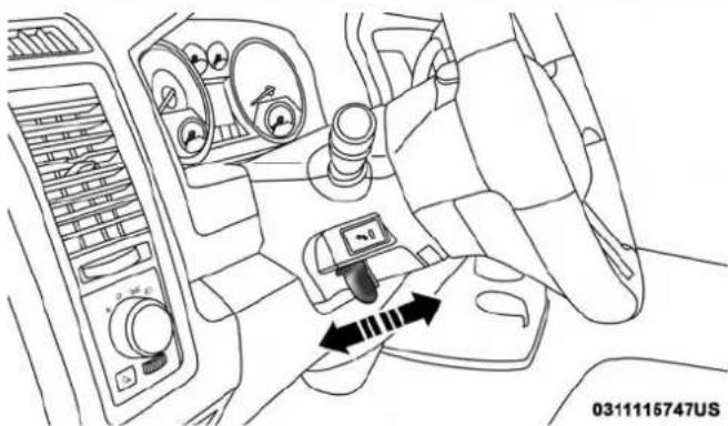
DRIVER ADJUSTABLE PEDALS — IF EQUIPPED
The adjustable pedals system is designed to allow a greater range of driver comfort for steering wheel tilt and seat position. This feature allows the brake, accelerator, and clutch pedals (if equipped) to move toward or away from the driver to provide improved position with the steering
wheel.

58 GETTING TO KNOW YOUR VEHICLE
The adjustable pedal switch is located to the left side of the steering column.
natural_image
Interior view of a car dashboard with steering wheel, air vent, and camera module (no text or symbols visible)AdjustablePedalsSwitch
• The pedals can be adjusted with the ignition OFF.
- The pedals cannot be adjusted when the vehicle is in REVERSE or when the Speed Control System is on. The following messages will appear on vehicles equipped with an instrument cluster display if the pedals are attempted to be adjusted when the system is locked out: "Adjustable Pedal Disabled — Cruise Control Engaged" or "Adjustable Pedal Disabled — Vehicle In Reverse".
NOTE:
• Always adjust the pedals to a position that allows full pedal travel.
• Further small adjustments may be necessary to find the best possible seat/pedal position.
- For vehicles equipped with Driver Memory Seat, you can use your remote keyless entry key fob or the memory switch on the driver's door trim panel to return the adjustable pedals to pre-programmed positions. Refer to "Driver Memory Seat" in "Getting To Know Your Vehicle" for further information.
WARNING!
Donotadjustthepedalswhilethevehicleismoving. Youcouldlosecontrolandhaveanaccident.Always adjustthepedalswhilethevehicleisparked.
CAUTION!
Donotplaceanyarticleundertheadjustablepedalsor impedeitsabilitytomove,asitmaycausedamagetothe pedalcontrols.Pedaltravelmaybecomelimitedifmovementisstoppedbyanobstructionintheadadjustable pedal(spath.
MIRRORS
Inside Day/Night Mirror — If Equipped
The mirror head can be adjusted up, down, left, and right for various drivers. The mirror should be adjusted to center on the view through the rear window.
Headlight glare from vehicles behind you can be reduced by moving the small control under the mirror to the night position (toward the rear of the vehicle). The mirror should be adjusted while set in the day position (toward the windshield).
Automatic Dimming Mirror — If Equipped
The mirror head can be adjusted up, down, left, and right for various drivers. The mirror should be adjusted to center on the view through the rear window.
This mirror automatically adjusts for headlight glare from vehicles behind you.
NOTE: The Automatic Dimming feature is disabled when the vehicle is in REVERSE to improve rear view viewing.

natural_image
Simple line drawing of a car front bumper with an arrow pointing to the lower side (no text or symbols)AdjustingRearviewMirror
0311114489US

DEALER ePROCESS
60 GETTING TO KNOW YOUR VEHICLE
The Automatic Dimming feature can be turned on or off through the touchscreen.
- Press the mirror dimmer button once to turn the feature on.
- Press the mirror dimmer button a second time to turn the feature off.
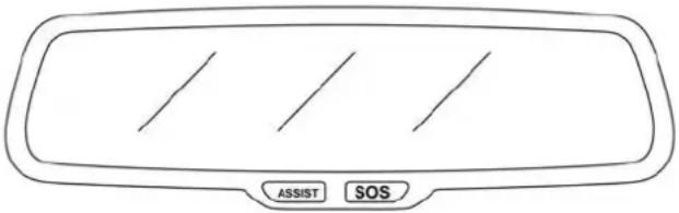
text_image
ASSIST SOS0306114048US
AutomaticDimmingMirror
CAUTION!
To avoid damage to the mirror during cleaning, never spray any cleanings solution directly onto the mirror. Apply the solution onto a clean cloth and wipe the mirror clean.
Automatic Dimming Mirror With Rear View Camera Display — If Equipped
A single ball joint mirror is provided in the vehicle. It is a twist on mirror that has a fixed position at the windshield. The mirror installs on the windshield button with a counterclockwise rotation and requires no tools for mounting. The mirror head can be adjusted up, down, left, and right for various drivers. The mirror should be adjusted to center on the view through the rear window.
This mirror automatically adjusts for headlight glare from vehicles behind you.
When the vehicle is placed into reverse gear, a video display illuminates to display the image generated by the rear view camera located on the tailgate handle. The auto dimming feature is also disabled to improve rear view viewing.
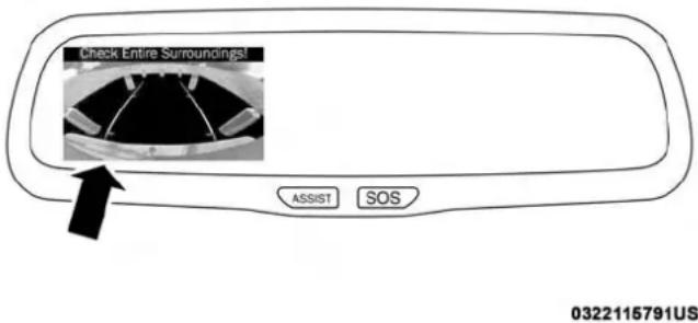
text_image
Check Entire Surroundings! ASSIST SOS 0322115791USAutomaticDimmingMirrorWithRearViewCamera
Outside Mirrors
To receive maximum benefit, adjust the outside mirrors to center on the adjacent lane of traffic with a slight overlap of the view obtained on the inside mirror.
NOTE: If your vehicle is equipped with illuminated approach lights under the outside mirrors, they can be turned off through the instrument cluster display or the Uconnect display. For further information, refer to "Instrument Cluster Display" in "Getting To Know Your Instrument Panel" or "Uconnect Settings" in "Multimedia".
WARNING!
Vehiclesandotherobjectsseeninthepassengerside convexmirrorwilllooksmallerandfartherawaythan theyreallyare.Relyingtoomuchonyourpassenger sideconvexmirrorcouldcauseyoutocollidewith anothervehicleorotherobject.Useyourinsidemirror whenjudgingthesizeordistanceofavehicleseenin thepassengersideconvexmirror.Somevehicleswill nothaveaconvexpassengersidemirror.
Driver's Outside Automatic Dimming Mirror — If Equipped
The driver's outside mirror will automatically adjust for glare from vehicles behind you. This feature is controlled by the inside automatic dimming mirror and will automatically adjust for headlight glare when the inside mirror
adjusts.

62 GETTING TO KNOW YOUR VEHICLE
Power Mirrors — If Equipped
The controls for the power mirrors are located on the driver's door trim panel.
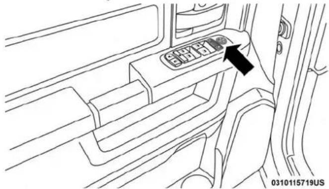
natural_image
Interior view of a car showing the dashboard and seat area with an arrow pointing to the left side (no text or symbols present)PowerMirrorControlsLocation
The power mirror controls consist of mirror select buttons and a four-way mirror control switch.
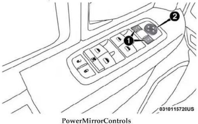
text_image
PowerMirrorControls 0310115720US1 — Mirror Select Buttons
2 — Four-Way Mirror Control Switch
GETTING TO KNOW YOUR VEHICLE 63
To adjust a mirror, push either the L (left) or R (right) button to select the mirror that you want to adjust.
Using the mirror control switch, push on any of the four arrows for the direction that you want the mirror to move.

text_image
PowerMirrorMovement 0310115717USPower Folding Outside Mirrors For Standard And Trailer Tow — If Equipped
If equipped with power folding mirrors, they can be electrically folded rearward and unfolded into the drive position.
The switch for the power folding mirrors is located between the power mirror switches L (left) and R (right). Push the switch once and the mirrors will fold in, push the switch a second time and the mirrors will return to the normal driving position.
If the mirror is manually folded after electrically cycled, a potential extra button push is required to get the mirrors back to the home position. If the mirror does not electrically fold, check for ice or dirt build up at the pivot area which can cause excessive drag.

text_image
PowerFoldingMirrorSwitch 0310115725US
64 GETTING TO KNOW YOUR VEHICLE
ResettingThePowerFoldingOutsideMirrors
You may need to reset the power folding mirrors if the following occurs:
- The mirrors are accidentally blocked while folding.
- The mirrors are accidentally manually folded/unfolded.
- The mirrors come out of the unfolded position.
- The mirrors shake and vibrate at normal driving speeds.
ToResetThePowerFoldingMirrors:
- Using the power folding mirror switch, move the mirror to its full forward position.
- Using the power folding mirror switch, move the mirror to the full retract position (this may require multiple button pushes). This resets them to their normal position.
NOTE:
- The power fold mirrors are designed to operate while the vehicle is stationary or traveling at moderate speeds. If you attempt to power fold the mirrors at high speeds they may not fully open or close. You should slow down to a moderate speed and complete the operation.
- When pushing the power fold button 10 or more times in one minute the system shuts down for one minute to protect the motors from over heating.
OutsideMirrorsFoldingFeature
All outside mirrors are designed to be able to be manually folded both forward and rearward to prevent damage.

natural_image
Diagram of a car interior showing a seatbelt component and dashboard (no text or symbols)FoldingMirror
CAUTION!
Itisrecommendedtofoldthemirrorsintothefull rearwardpositiontoresistdamagewhenenteringacar washoranarrowlocation.
Trailer Towing Mirrors — If Equipped
These mirrors are designed with an adjustable mirror head to provide a greater vision range when towing extra-wide loads. To change position inboard or outboard, the mirror head should be rotated (flipped in or out).

natural_image
Diagram of a car side mirror with an arrow pointing to the front wheel (no text or symbols on the mirror itself)TrailerTowingPosition
NOTE: Fold the trailer towing mirrors rearward prior to entering an automated car wash.
66 GETTING TO KNOW YOUR VEHICLE
A small blindspot mirror is located next to main mirror and can be adjusted separately.
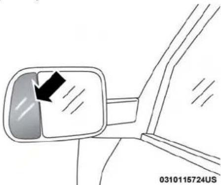
natural_image
Diagram of a car side mirror with an arrow indicating direction, no text or symbols presentBlindspotMirror
Heated Mirrors — If Equipped

These mirrors are heated to melt frost or ice. This feature will be activated whenever you turn on the rear window defroster (if equipped). Refer to "Climate Controls" in this section for further information.
Tilt Side Mirrors In Reverse — If Equipped
Tilt Side Mirrors In Reverse provides automatic outside mirror positioning which will aid the driver's view of the ground rearward of the front doors. The outside mirrors will move slightly downward from the present position when the vehicle is shifted into REVERSE. The outside mirrors will then return to the original position when the vehicle is shifted out of the REVERSE position. Each stored memory setting will have an associated Tilt Side Mirrors In Reverse position.
NOTE: The Tilt Side Mirrors In Reverse feature is not turned on when delivered from the factory.
This feature can be programmed through the Uconnect system. Refer to "Uconnect Settings" in "Multimedia" for further information.

Illuminated Vanity Mirror — If Equipped
Illuminated vanity mirrors are located on each sun visor. To use the mirror, rotate the sun visor down and swing the mirror cover upward. The lights will turn on automatically. Closing the mirror cover turns off the light.

natural_image
Diagram of a car interior showing a mounted device with an arrow pointing to it, no text or symbols present.Illuminated VanityMirror
"Slide-On-Rod"FeaturesOfSunVisor—If Equipped
The sun visor "Slide-On-Rod" feature allows for additional flexibility in positioning the visor to block out the sun.
To use the "Slide-On-Rod" feature, rotate the sun visor downward and unclip it. Pull the sun visor along the "Slide-On-Rod" until the sun visor is in the desired position.
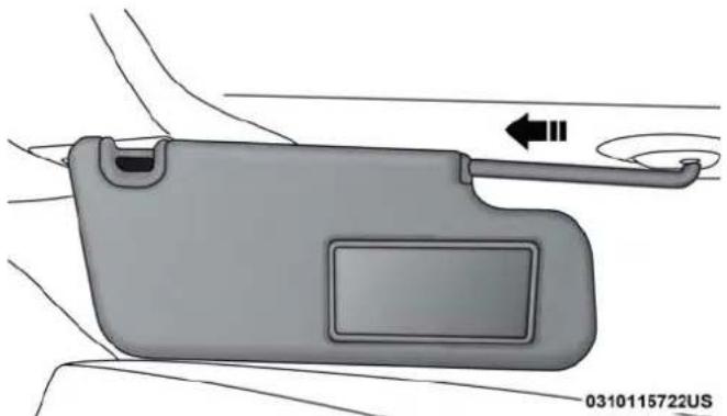
natural_image
Diagram of a car interior showing the front compartment and side arm, with no readable text or symbols."Slide-On-Rod"Extender
68 GETTING TO KNOW YOUR VEHICLE
EXTERIOR LIGHTS
Headlight Switch
The headlight switch is located on the left side of the instrument panel, next to the steering wheel. The headlight switch controls the operation of the headlights, parking lights, instrument panel lights, cargo lights and fog lights (if equipped).
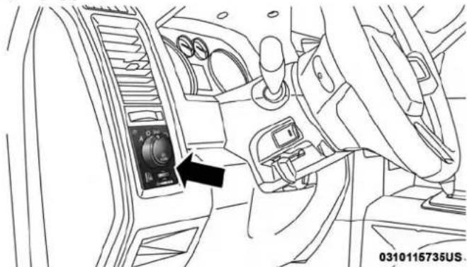
natural_image
Interior view of a car dashboard with a control panel and directional arrows (no text or symbols)HeadlightSwitchLocation
Your vehicle is equipped with plastic headlight and fog light (if equipped) lenses that are lighter and less susceptible to stone breakage than glass lights. Plastic is not as scratch resistant as glass and therefore different lens cleaning procedures must be followed.
To minimize the possibility of scratching the lenses and reducing light output, avoid wiping with a dry cloth. To remove road dirt, wash with a mild soap solution followed by rinsing.
NOTE: If your vehicle is equipped with illuminated approach lights under the outside mirrors they can be turned off through the instrument cluster display or the Uconnect radio. For further information refer to "Instrument Cluster Display" in "Getting To Know Your Instrument Panel" and "Uconnect Settings" in "Multimedia".
CAUTION!
Donotuseabrasivecleaningcomponents,solvents,steelwoolorotherabrasivematerialstocleanthe lenses.

Headlights
To turn on the headlights, rotate the headlight switch clockwise to the headlight position. When the headlight switch is on, the parking lights, taillights, license plate light and instrument panel lights are also turned on. To turn off the headlights, rotate the headlight switch back to the O (off) position.

text_image
AUTO 30°E 30°E PUSH0311116387US
HeadlightPosition
Daytime Running Lights (DRL) — If Equipped
The headlights on your vehicle will illuminate when the engine is started and the transmission is in any gear except PARK. This provides a constant "lights on" condition until the ignition is turned OFF. The lights illuminate at less than half of normal intensity. If the parking brake is applied, the Daytime Running Lights (DRL) will turn off. Also, if a turn signal is activated, the DRL lamp on the same side of the vehicle may turn off for the duration of the turn signal activation. Once the turn signal is no longer active, the DRL lamp will illuminate.
Multifunction Lever
The multifunction lever is located on the left side of the steering column.

70 GETTING TO KNOW YOUR VEHICLE
High/Low Beam Switch
Push the multifunction lever toward the instrument panel to switch the headlights to high beam. Pulling the multifunction lever back toward the steering wheel will turn the low beams back on, or shut the high beams off.

natural_image
Interior view of a car dashboard with steering wheel and gauges (no text or symbols visible)High/LowBeamSwitch
Automatic High Beam Headlamp Control — If Equipped
The Automatic High Beam Headlamp Control system provides increased forward lighting at night by automating high beam control through the use of a digital camera mounted on the inside rearview mirror. This camera detects vehicle specific light and automatically switches from high beams to low beams until the approaching vehicle is out of view.
NOTE:
- The Automatic High Beam Headlamp Control can be turned on or off by selecting "ON" under "Auto Dim High Beams" within your Uconnect settings, as well as turning the headlight switch to the AUTO position. Refer to "Uconnect Settings" in "Multimedia" for further information.
- Broken, muddy, or obstructed headlights and taillights of vehicles in the field of view will cause headlights to remain on longer (closer to the vehicle). Also, dirt, film, and other obstructions on the windshield or camera lens will cause the system to function improperly.
If the windshield or Automatic High Beam Headlamp Control mirror is replaced, the mirror must be re-aimed to ensure proper performance. See a local authorized dealer.
ToActivate
- The Automatic High Beams are enabled through the Uconnect system. Refer to "Uconnect Settings" in "Multimedia" for further information.

- Turn the headlight switch to the AUTO headlight position.
- Push the multifunction lever away from you (toward front of vehicle) to engage the high beam mode.
NOTE: This system will not activate until the vehicle is at or above 20 mph (32 km/h).
ToDeactivate
- Pull the multifunction lever toward you (or rearward in vehicle) to manually deactivate the system (normal operation of low beams).
- Push back on the multifunction lever to reactivate the system.
Flash-To-Pass
You can signal another vehicle with your headlights by lightly pulling the multifunction lever toward you. This will cause the high beam headlights to turn on, and remain on, until the lever is released.
Automatic Headlights — If Equipped
This system automatically turns the headlights on or off according to ambient light levels. To turn the system on, rotate the headlight switch counterclockwise to the
position. When the system is on, the headlight time delay feature is also on. This means the headlights will stay on for up to 90 seconds after you place the ignition into the OFF position. The headlight time delay can be programmed 0/30/60/90 seconds. Refer to "Uconnect Settings" in "Multimedia" for further information.
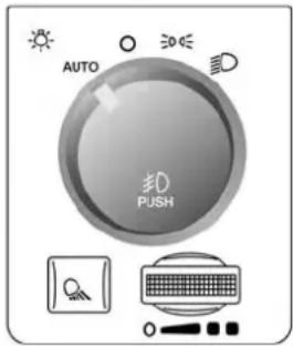
text_image
AUTO PUSH0311115741US
AutomaticHeadlightPosition
To turn the automatic system off, move the headlight switch out of the AUTO position.
NOTE: The engine must be running before the headlights will turn on in the Automatic Mode.

72 GETTING TO KNOW YOUR VEHICLE
Parking Lights And Panel Lights

To turn on the parking lights and instrument panel lights, rotate the headlight switch clockwise. To turn off the parking lights, rotate the headlight switch back to the O (off) position.
Headlights On With Wipers (Available With Automatic Headlights Only)
When this feature is active, the headlights will turn on approximately 10 seconds after the wipers are turned on if the headlight switch is placed in the AUTO position. In addition, the headlights will turn off when the wipers are turned off, if they were turned on by this feature.
NOTE: This feature can be programmed through the Uconnect system. Refer to "Uconnect Settings" in "Multimedia" for further information.
Headlight Delay
To aid in your exit, your vehicle is equipped with a headlight delay that will leave the headlights on for approximately up to 90 seconds. This delay is initiated when the ignition is turned off while the headlight switch is on, and then the headlight switch is cycled off. Headlight delay can be canceled by either turning the headlight switch on then off, or by turning the ignition to the ON/RUN position.
NOTE: This feature can be programmed through the Uconnect system. Refer to "Uconnect Settings" in "Multimedia" for further information.
Lights-On Reminder
If the headlights, parking lights, or cargo lights are left on after the ignition is turned OFF, a chime will sound when the driver's door is opened.

Fog Lights — If Equipped
The fog lights are turned on by rotating the headlight switch to the parking light or headlight position and pushing in the headlight rotary control.
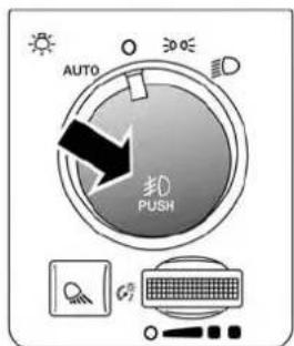
text_image
AUTO 0.0 0.0 0.0 0.0 0.0 0.0 0.0 0.0 0.0 0.0 0.0 0.0 0.0 0.0 0.0 0.0 0.0 0.0 0.0 0.0 0.0 0.0 0.0 0.0 0.0 0.1 0.2 0.3 0.4 0.5 0.6 0.7 0.8 0.9 1.0 1.1 1.2 1.3 1.4 1.5 1.6 1.7 1.8 1.9 2.0 2.1 2.2 2.3 2.4 2.5 2.6 2.7 2.8 2.9 3.0 3.1 3.2 3.3 3.4 3.5 3.6 3.7 3.8 3.9 4.0 4.1 4.2 4.3 4.4 4.5 4.6 4.7 4.8 4.9 5.00311115742US
FogLightSwitch
The fog lights will operate only when the parking lights are on or when the vehicle headlights are on low beam. An indicator light located in the instrument cluster display will illuminate when the fog lights are on. The fog lights will turn off when the switch is pushed a second time, when the headlight switch is rotated to the off position, or the high beam is selected.
Turn Signals
Move the multifunction lever up or down and the arrows on each side of the instrument cluster display will flash to show proper operation of the front and rear turn signal lights.

text_image
0311115745USTurnSignalLever
NOTE: If either light remains on and does not flash, or there is a very fast flash rate, check for a defective outside light bulb. If an indicator fails to light when the lever is moved, it would suggest that the indicator bulb is defective.

74 GETTING TO KNOW YOUR VEHICLE
Lane Change Assist — If Equipped
Tap the multifunction lever up or down once, without moving beyond the detent, and the turn signal (right or left) will flash three times then automatically turn off.
Cargo Light
The cargo light is turned on by pushing on the cargo light button.

text_image
AUTO 30.0 30.0 30.0 30.0 30.0 30.0 30.0 30.0 30.0 30.0 30.0 30.0 30.0 30.0 30.0 30.0 30.0 30.0 30.0 30.0 30.10311115744US
CargoLightButton
The cargo light will also turn on for approximately 60 seconds when the unlock button on a key fob is pushed, as part of the Illuminated Entry feature.
Battery Saver
To protect the life of your vehicle's battery, load shedding is provided for both the interior and exterior lights.
If the ignition is OFF and any door is left ajar for 10 minutes or the dimmer control is rotated all the way up to the dome on position for 10 minutes, the interior lights will automatically turn off.
NOTE: Battery saver mode is canceled if the ignition is ON.
If the headlights remain on while the ignition is cycled OFF, the exterior lights will automatically turn off after eight minutes. If the headlights are turned on and left on for eight minutes while the ignition is OFF, the exterior lights will automatically turn off.
INTERIOR LIGHTS
Courtesy Lights
Courtesy and dome lights are turned on when the front doors are opened, when the dimmer control (rotating wheel on the bottom of the switch) is rotated to the far right detent position. If your vehicle is equipped with Remote Keyless Entry, and the unlock button is pushed on the key fob, the courtesy and dome lights will turn on.
Courtesy/ReadingLights
Both lights in the overhead console and rear passenger compartment will illuminate as courtesy lights when a door is opened, when the dimmer control is rotated to the courtesy light position (full right position), or when the unlock button is pushed on the Remote Keyless Entry key fob, if equipped. These lights are also operated individually as reading lights by pushing on the corresponding lens.

text_image
0311115749USFrontCourtesy/ReadingLights

natural_image
Close-up of a computer control panel with a sun icon and an arrow pointing to it (no text or symbols on the panel itself)RearPassengerCourtesy/ReadingLight
NOTE: The courtesy/reading lights will remain on until the switch is pushed a second time, so be sure they have been turned off before exiting the vehicle. If the interior lights are left on after the ignition is turned off, they will automatically turn off after 15 minutes.
76 GETTING TO KNOW YOUR VEHICLE
AmbientLight
The overhead console is equipped with an ambient light feature. This light casts illumination for improved visibility of the floor console area.

text_image
AmbientLight 0311115761USDimmerControl
The brightness of the instrument panel as well as the ambient lighting can be regulated by rotating the dimmer control to the right (brighter) or to the left (dimmer).
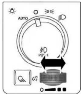
text_image
AUTO ED PUI-10311115743US
DimmerControl
"PartyMode"
When a door is open and the interior lights are on, rotating the dimmer control all the way left, to the off detent, will cause all the interior lights to go out. This is also known as the "Party" mode because it allows the doors to stay open for extended periods of time without discharging the vehicle's battery.
"ParadeMode"
When the headlights are on you can supplement the brightness of the odometer, trip odometer, radio and overhead console by rotating the control to the right until
you hear a click. This feature is termed the "Parade" mode and is useful when headlights are required during the day.
NOTE: If your vehicle is equipped with a touchscreen, the dimming of the touchscreen is programmable through the Uconnect system. Refer to "Uconnect Settings" in "Multimedia" for further details.
Illuminated Approach
The courtesy lights will turn on when you use the key fob to unlock the doors or open any door.
This feature also turns on the approach lighting in the outside mirrors (if equipped). Refer to "Mirrors" in "Getting To Know Your Vehicle" for further information.
The lights will fade to off after approximately 30 seconds, or they will immediately fade to off once the ignition switch is turned to ON/RUN from the OFF position.
The front courtesy overhead console and door courtesy lights will not turn off if the dimmer control is in the "Dome ON" position (rotate vertical thumb wheel all the way to the top detent).
The illuminated entry system will not operate if the dimmer control is in the "Dome OFF" position (rotate vertical thumb wheel all the way to the bottom de tent). NOTE: If your vehicle is equipped with illuminated approach lights under the outside mirrors, they can be turned off by moving the instrument panel dimmer into the "Dome Defeat" detent position.
WINDSHIELD WIPERS AND WASHERS
Windshield Wipers
The wipers and washers are operated by a switch in the multifunction lever. Turn the end of the lever to select the desired wiper speed.

text_image
MUST PUSH 0322115792USWindshieldWiper/WasherSwitch

Rotate the end of the lever upward, to the first detent past the intermittent settings for low-speed wiper operation. Rotate the end of the lever upward to the second detent past the intermittent settings for high-speed wiper operation.
IntermittentWiperSystem
The intermittent feature of this system was designed for use when weather conditions make a single wiping cycle, with a variable pause between cycles, desirable. For maximum delay between cycles, rotate the control knob upward to the first detent.
The delay interval decreases as you rotate the knob until it enters the low continual speed position. The delay can be regulated from a maximum of about 18 seconds between cycles, to a cycle every one second. The delay intervals will double in duration when the vehicle speed is 10 mph (16 km/h) or less.
WindshieldWashers
To use the windshield washer, push the washer knob, located on the end of the multifunction lever, inward to the second detent. Washer fluid will be sprayed and the wiper will operate for two to three cycles after the washer knob is released from this position.
If the washer knob is depressed while in the delay range, the wiper will operate for several seconds after the washer knob is released. It will then resume the intermittent interval previously selected. If the washer knob is pushed while in the off position, the wiper will turn on and cycle approximately three times after the wash knob is released.
To prevent freeze-up of your windshield washer system in cold weather, select a solution or mixture that meets or exceeds the temperature range of your climate. This rating information can be found on most washer fluid containers.
WARNING!
Suddenlossofvisibilitythroughthewindshieldcould leadtoacollision.Youmightnotseeothervehiclesor otherobstacles.Toavoidsuddenicingofthewindshieldduringfreezingweather,warmthewindshield withthedefrosterbeforeandduringwindshield washeruse.
MistFeature
When a single wipe to clear off road mist or spray from a passing vehicle is needed, push the washer knob, located

on the end of the multifunction lever, inward to the first detent and release. The wipers will cycle one time and automatically shut off.
NOTE: The mist feature does not activate the washer pump; therefore, no washer fluid will be sprayed on the windshield. The wash function must be used in order to spray the windshield with washer fluid.
Rain Sensing Wipers — If Equipped
This feature senses moisture on the windshield and automatically activates the wipers for the driver. The feature is especially useful for road splash or overspray from the windshield washers of the vehicle ahead. Rotate the end of the multifunction lever to one of five settings to activate this feature.
NOTE: This feature can be programmed through the Uconnect system. Refer to "Uconnect Settings" in "Multimedia" for further information.
The sensitivity of the system can be adjusted with the multifunction lever. Wiper delay position 1 is the least sensitive, and wiper delay position 5 is the most sensitive. Position 3 should be used for normal rain conditions. Positions 1 and 2 can be used if the driver desires less
wiper sensitivity. Positions 4 and 5 can be used if the driver desires more sensitivity. Place the wiper switch in the O (off) position when not using the system.
NOTE:
- The Rain Sensing feature will not operate when the wiper switch is in the low or high-speed position.
- The Rain Sensing feature may not function properly when ice, or dried salt water is present on the windshield.
- Use of Rain-X or products containing wax or silicone may reduce Rain Sensing performance.
The Rain Sensing system has protection features for the wiper blades and arms, and will not operate under the following conditions:
- Low Ambient Temperature — When the ignition is first turned ON, the Rain Sensing system will not operate until the wiper switch is moved, vehicle speed is greater than 0 mph (0 km/h), or the outside temperature is greater than 32°F (0°C).

80 GETTING TO KNOW YOUR VEHICLE
- Transmission In NEUTRAL Position — When the ignition is ON, and the transmission is in the NEUTRAL position, the Rain Sensing system will not operate until the wiper switch is moved, vehicle speed is greater than 5 mph (8 km/h), or the gear selector is moved out of the NEUTRAL position.
- RemoteStartModeInhibit— On vehicles equipped with Remote Starting system, Rain Sensing wipers are not operational when the vehicle is in the remote start mode. Once the operator is in the vehicle and has placed the ignition switch in the RUN position, Rain Sensing wiper operation can resume, if it has been selected, and no other inhibit conditions (mentioned previously) exist.
CLIMATE CONTROLS
Manual Climate Controls Without Touchscreen
The controls for the manual heating and air conditioning system in this vehicle consist of a series of outer rotary dials and inner push knobs. These comfort controls can be set to obtain desired interior conditions.
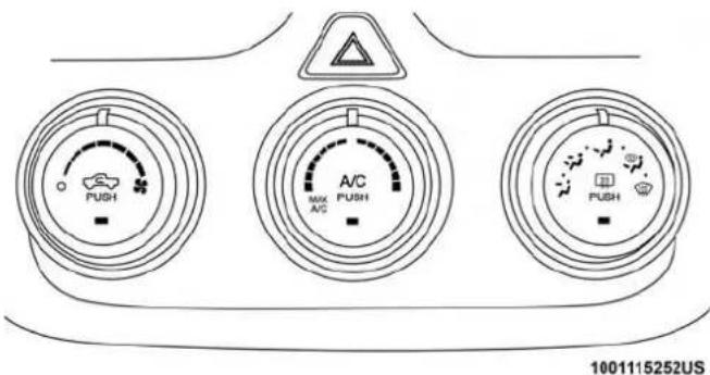
text_image
PUSH A/C MAX A/C PUSH 1001115252USManualClimateControlsWithoutATouchscreen

ManualClimateControlDescriptions
| IconDescription | |
 | MAXA/CSettingRotate the Temperature Control Knob counterclockwise until it is set to MAX A/C. This is the coldest setting and will put the A/C to its maximum power. |
 | A/CButtonPush the A/C button to engage the Air Conditioning (A/C). A LED will illuminate when the A/C system is engaged. |
 | RecirculationButtonPush and release this button to change the system between recirculation mode and outside air mode. Recirculation can be used when outside conditions such as smoke, odors, dust, or high humidity are present.NOTE:Continuous use of the Recirculation mode may make the inside air stuffy and window fogging may occur. Extended use of this mode is not recommended.The use of the Recirculation mode in cold or damp weather could cause windows to fog on the inside, because of moisture buildup inside the vehicle. Select the outside air position for maximum defogging.Recirculation can be used in all modes except for Defrost.The A/C can be deselected manually without disturbing the mode control selection. |
82 GETTING TO KNOW YOUR VEHICLE
| IconDescription | |
 FRONT FRONT | FrontDefrostSettingTurn the Mode Control knob to the Defrost mode. Air comes from the windshield and side window demist outlets. Use Defrost mode with maximum temperature settings for best windshield and side window defrosting and defogging. |
 REAR REAR | RearDefrostButtonPush and release the Rear Defrost Control button to turn on the rear window defroster and the heated outside mirrors (if equipped). An indicator will illuminate when the rear window defroster is on. The rear window defroster automatically turns off after ten minutes. |
 | TemperatureControlUse this control knob to regulate the temperature of the air inside the passenger compartment. Rotating the knob counterclockwise, from top center into the blue area of the scale, indicates cooler temperatures. Rotating the knob clockwise, into the red area, indicates warmer temperatures. |
  | BlowerControlThere are seven blower speeds. Use this control knob to regulate the amount of air forced through the system in any mode you select. The blower speed increases as you move the control clockwise from the off position.ModesControl:Rotate the Mode Control Knob to change the airflow distribution mode. The airflow distribution mode can be adjusted so air comes from the instrument panel outlets, floor outlets, defrost outlets and demist outlets. The Mode settings are as follows: |
PanelMode | PanelModeAir comes from the outlets in the instrument panel. Each of these outlets can be individually adjusted to direct the flow of air. The air vanes of the center outlets and outboard outlets can be moved up and down or side to side to regulate airflow direction. There is a shut off wheel located below the air vanes to shut off or adjust the amount of airflow from these outlets. |
Bi-LevelMode | Bi-LevelModeAir comes from the instrument panel outlets and floor outlets. A slight amount of air is directed through the defrost and side window demister outlets.NOTE:Bi-Level mode is designed under comfort conditions to provide cooler air out of the panel outlets and warmer air from the floor outlets. |
FloorMode | FloorModeAir comes from the floor outlets. A slight amount of air is directed through the defrost and side window demister outlets. |
84 GETTING TO KNOW YOUR VEHICLE
| IconDescription | |
MixMode | MixModeAir is directed through the floor, defrost, and side window demister outlets. This setting works best in cold or snowy conditions that require extra heat to the windshield. This setting is good for maintaining comfort while reducing moisture on the windshield. |
EconomyMode
If ECONOMY mode is desired, push the A/C button to turn off the LED indicator and the A/C compressor. Rotate the temperature control knob to the desired temperature. Also, make sure to select only Panel, Bi-Level or Floor modes.

Automatic Climate Controls With A Touchscreen

text_image
10:10 Max A/C A/C Air Condition Air Filter Temperature 70 78 Air Fan A Mode Air Air Sync Auto Climate Off Screened OFF Back SPOKSWED ENTER AUTO A/C - - - - - - - - - - - - - - - - - - - - - - - - - - - - - - - - - - - - - - - - - - - - - - - - - - - - - - - - - - - - - - - - - - - - - - - - - - -Uconnect3With5-inchDisplayWithAutomaticTemperatureControls
1001115253US

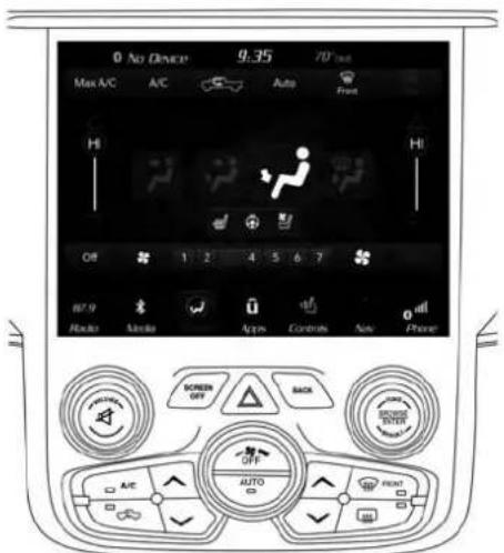
text_image
0 No Device 9:35 70 Hz Max A/C A/C Auto Front Hi Off 1 2 4 5 6 7 87.9 Radio Audio Apps Controls Spin Power SCREEN OFF BACK AUTO A/EUconnect4C/4CNAVWithAutomaticTemperatureControls
0313129069US

ControlDescriptions
NOTE: Icons and descriptions can vary based upon vehicle equipment.
| IconDescription | |
| MAXA/C | MAXA/CButtonPress and release to change the current setting, the indicator illuminates when MAX A/C is on. Performing this function again will cause the MAX A/C operation to switch into manual mode and the MAX A/C indicator will turn off. |
| A/C | A/CButtonPress and release the button on the touchscreen, or push and release the button on the faceplate, to change the current setting, the indicator illuminates when A/C is on. |
88 GETTING TO KNOW YOUR VEHICLE
| IconDescription | |
 | RecirculationButtonPress and release this button to change the system between recirculation mode and outside air mode. Recirculation can be used when outside conditions such as smoke, odors, dust, or high humidity are present.NOTE:Continuous use of the Recirculation mode may make the inside air stuffy and window fogging may occur. Extended use of this mode is not recommended.The use of the Recirculation mode in cold or damp weather could cause windows to fog on the inside, because of moisture buildup inside the vehicle. Select the outside air position for maximum defogging.Recirculation can be used in all modes except for Defrost.The A/C can be deselected manually without disturbing the mode control selection. |
| AUTO | AUTOButton—IfEquippedAutomatically controls the interior cabin temperature by adjusting airflow distribution and amount. Toggling this function will cause the system to switch between manual mode and automatic modes. Refer to “Automatic Operation” within this section for more information. |

GETTING TO KNOW YOUR VEHICLE 89
| IconDescription | |
 | FrontDefrostButtonPress and release the touchscreen button, or push and release the button on the faceplate, to change the current airflow setting to Defrost mode. The indicator illuminates when this feature is on. Air comes from the windshield and side window demist outlets. When the defrost button is selected, the blower level may increase. Use Defrost mode with maximum temperature settings for best windshield and side window defrosting and defogging. When toggling the front defrost mode button, the climate system will return to previous setting. |
 | RearDefrostButtonPush and release the button on the touchscreen, or push and release the button on the faceplate, to turn on the rear window defroster and the heated outside mirrors (if equipped). An indicator will illuminate when the rear window defroster is on. The rear window defroster automatically turns off after ten minutes. |
Uconnect3 | DriverandPassengerTemperatureUpandDownButtonsProvides the driver and passenger with independent temperature control. Push the up arrow button on the faceplate, press the up arrow button on the touchscreen, or press and slide the temperature bar towards the red arrow button on the touchscreen for warmer temperature settings. Push the down arrow button on the faceplate, press the down arrow button on the touchscreen, or press and slide the temperature bar towards the blue arrow button on the touchscreen for cooler temperature settings. When the SYNC feature is active, the passenger's temperature will move up and down with the driver's temperature, when it is increased and decreased, respectively. |
Uconnect4C/4CNAV | NOTE:Temperature numbers will only be displayed if the system is equipped with Automatic Temperature Control. |
| SYNC | SYNCButton—IfEquippedPress the SYNC button on the touchscreen to toggle the SYNC feature on/off. The SYNC indicator is illuminated when this feature is enabled. SYNC is used to synchronize the passenger temperature setting with the driver temperature setting. The SYNC feature also synchronizes the rear passengers' temperature to the driver temperature setting. Changing the passenger temperature setting while in SYNC will automatically exit this feature. |
FaceplateKnob | BlowerControlBlower Control is used to regulate the amount of air forced through the climate system. There are seven blower speeds available. The speeds can be selected using either the blower control knob on the faceplate or the buttons on the touchscreen.Faceplate:The blower speed increases as you turn the blower control knob clockwise from the lowest blower setting. The blower speed decreases as you turn the blower control knob counterclockwise.Touchscreen:Use the small blower icon to reduce the blower setting and the large blower icon to increase the blower setting. Blower can also be selected by pressing the blower bar area between the icons. For Uconnect 3, press the button to access the blower screen and control the blower. |
TouchscreenButtons | |
PanelModePanel | ModeAir comes from the outlets in the instrument panel. Each of these outlets can be individually adjusted to direct the flow of air. The air vanes of the center outlets and outboard outlets can be moved up and down or side to side to regulate airflow direction. There is a shut off wheel located below the air vanes to shut off or adjust the amount of airflow from these outlets. |
92 GETTING TO KNOW YOUR VEHICLE
| IconDescription | |
Bi-LevelMode | Bi-LevelModeAir comes from the instrument panel outlets and floor outlets. A slight amount of air is directed through the defrost and side window demister outlets.NOTE:Bi-Level mode is designed under comfort conditions to provide cooler air out of the panel outlets and warmer air from the floor outlets. |
FloorMode | FloorModeAir comes from the floor outlets. A slight amount of air is directed through the defrost and side window demister outlets. |
MixMode | MixModeAir is directed through the floor, defrost, and side window demister outlets. This setting works best in cold or snowy conditions that require extra heat to the windshield. This setting is good for maintaining comfort while reducing moisture on the windshield. |
| OFF | ClimateControlOFFButtonPress and release this button on the touchscreen, or push the faceplate button, to turn the Climate Control System off. |
Climate Control Functions
A/C(AirConditioning)
The Air Conditioning (A/C) button allows the operator to manually activate or deactivate the air conditioning system. When the air conditioning system is turned on, cool dehumidified air will flow through the outlets into the cabin. For improved fuel economy, press the A/C button to turn off the air conditioning and manually adjust the blower and airflow mode settings. Also, make sure to select only Panel, Bi-Level, or Floor modes.
NOTE:
- If fog or mist appears on the windshield or side glass, select Defrost mode, and increase blower speed if needed.
- If your air conditioning performance seems lower than expected, check the front of the A/C condenser (located in front of the radiator), for an accumulation of dirt or insects. Clean with a gentle water spray from the front of the radiator and through the condenser.
MAXA/C
MAX A/C sets the control for maximum cooling performance.
Press and release to toggle between MAX A/C and the prior settings. The button illuminates when MAX A/C is on.
In MAX A/C, the blower level and mode position can be adjusted to desired user settings. Pressing other settings will cause the MAX A/C operation to switch to the selected setting and MAX A/C to exit.
Recirculation
In cold weather, use of Recirculation mode may lead to excessive window fogging. The Recirculation feature may be unavailable (button on the touchscreen greyed out) if conditions exist that could create fogging on the inside of the windshield.
On systems with Manual Climate Controls, the Recirculation mode is not allowed in Defrost mode to improve window clearing operation. Recirculation is disabled automatically if this mode is selected. Attempting to use Recirculation while in this mode causes the LED in the control button to blink and then turns off.

Automatic Temperature Control (ATC) — If Equipped
AutomaticOperation
- Push the AUTO button on the faceplate, or the AUTO button on the touchscreen on the Automatic Temperature Control (ATC) Panel.
- Next, adjust the temperature you would like the system to maintain by adjusting the driver and passenger temperature control buttons. Once the desired temperature is displayed, the system will achieve and automatically maintain that comfort level.
- When the system is set up for your comfort level, it is not necessary to change the settings. You will experience the greatest efficiency by simply allowing the system to function automatically.
NOTE:
- It is not necessary to move the temperature settings for cold or hot vehicles. The system automatically adjusts the temperature, mode, and blower speed to provide comfort as quickly as possible.
- The temperature can be displayed in U.S. or Metric units by selecting the US/Metric customer-programmable feature. Refer to the “Uconnect Settings” in “Multimedia” for further information.
To provide you with maximum comfort in the Automatic mode during cold start-ups, the blower fan will remain on low until the engine warms up. The blower will increase in speed and transition into Auto mode.
ManualOperationOverride
This system offers a full complement of manual override features. The AUTO symbol in the front ATC display will be turned off when the system is being used in the manual mode.
Operating Tips
NOTE: Refer to the chart at the end of this section for suggested control settings for various weather conditions.
SummerOperation
The engine cooling system must be protected with a high-quality antifreeze coolant to provide proper corrosion protection and to protect against engine overheating. OAT coolant (conforming to MS.90032) is recommended.
WinterOperation
To ensure the best possible heater and defroster performance, make sure the engine cooling system is functioning properly and the proper amount, type, and concentration of coolant is used. Use of the Air Recirculation mode during Winter months is not recommended, because it may cause window fogging.
Vacation/Storage
Before you store your vehicle, or keep it out of service (i.e., vacation) for two weeks or more, run the air conditioning system at idle for about five minutes, in fresh air with the blower setting on high. This will ensure adequate system lubrication to minimize the possibility of compressor damage when the system is started again.
WindowFogging
Vehicle windows tend to fog on the inside in mild, rainy, and/or humid weather. To clear the windows, select Defrost or Mix mode and increase the front blower speed. Do not use the Recirculation mode without A/C for long periods, as fogging may occur.
CAUTION!
Failure to follow these cautions can cause damage to the heating elements:
- Usecarewhenwashingtheinsideoftherearwindow.Donotuseabrasivewindowcleanersonthe interiorsurfaceofthewindow.Useasoftclothanda mildwashingsolution,wipingparalleltotheheatingelements.Labelscanbepeeledoffaftersoaking withwarmwater.
- Donotusescrapers, sharpinstruments, or abrasive windowcleanersontheinteriorsurfaceofthewindow.
- Keepallobjectsasafedistancefromthewindow.
96 GETTING TO KNOW YOUR VEHICLE
OutsideAirIntake
Make sure the air intake, located directly in front of the windshield, is free of obstructions, such as leaves. Leaves collected in the air intake may reduce airflow, and if they enter the plenum, they could plug the water drains. In Winter months, make sure the air intake is clear of ice, slush, and snow.
CabinAirFilter
The climate control system filters out dust and pollen from the air. Contact an authorized dealer to service your cabin air filter, and to have it replaced when needed.
OperatingTipsChart
| WEATHER | CONTROL SETTINGS |
Hot weather and vehicle interior is very hot | Set the mode control to  on, and blower on high. Roll down the windows for a minute to flush out the hot air. Once comfort is achieved adjust controls for comfort. on, and blower on high. Roll down the windows for a minute to flush out the hot air. Once comfort is achieved adjust controls for comfort. |
Warm weather |  on and set the mode control to the on and set the mode control to the |
| Cool Sunny | Operate in position. |
Cool & Humid conditions _d  |  control to control to 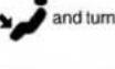 on vs clear. [SDWW] on vs clear. [SDWW] |
Co  | Set the mode control to the position. If windshield fogging starts to occur, move the control towards the position.  |
8000cb71
WINDOWS
Power Windows — If Equipped

text_image
0301117805USPowerWindowSwitches
The power window controls located on the driver's door trim panel have up—down switches that give you fingertip control of all power windows. There is a single opening and closing switch on the front passenger door for passenger window control and on the rear doors of the Crew Cab models. The windows will operate when the ignition switch is turned to the ON/RUN or ACC position, and for up to 10 minutes after the ignition is turned OFF or until a front door is opened.
GETTING TO KNOW YOUR VEHICLE 97
NOTE: The Key Off Power Delay feature will allow the power windows to operate for up to 10 minutes after the ignition is turned OFF. This feature is cancelled when either front door is opened.
WARNING!
Neverleavechildrenunattendedinvehicle.Donot leavethekeyfobinornearthevehicleorinalocation accessibletochildren, and donotleavetheignition of avehicleequipped with KeylessEnter-N-Gointhe ACCorON/RUNmode. Occupants, particularly unattended children, can become entrapped by the windows while operating the power window switches. Such entrapment may result in serious injury or death.
Auto-Down
Both the driver and front passenger window switch have an Auto-Down feature. Push the window switch past the first detent, release, and the window will go down automatically. To cancel the Auto-Down movement, operate the switch in either the up or down direction and release the switch.
To stop the window from going all the way down during the Auto-Down operation, pull up on the switch briefly.

98 GETTING TO KNOW YOUR VEHICLE
To open the window part way, push to the switch to the first detent and release it when you want the window to stop.
Auto-UpFeatureWithAnti-PinchProtection(4-Door ModelsDriverAndFrontPassengerDoorOnly)—IfEquipped
Pull the window switch fully upward to the second detent, release, and the window will go up automatically.
To stop the window from going all the way up during the Auto-Up operation, push down on the switch briefly.
To close the window part way, lift the window switch to the first detent and release when you want the window to stop.
NOTE: If the window runs into any obstacle during the Auto-Closure, it will reverse direction and then go back down. Remove the obstacle and use the window switch again to close the window. Any impact due to rough road conditions may trigger the auto reverse function unexpectedly during auto closure. If this happens, pull the switch lightly to the first detent and hold to close the window manually.
WARNING!
Thereisnoanti-pinchprotectionwhenthewindowis almostclosed.Besuretoclearallobjectsfromthe windowbeforeclosing.
ResetAuto-Up
Should the Auto-Up feature stop working, the window may need to be reset. To reset Auto-Up:
- Make sure the door is fully closed.
- Pull the window switch up to close the window completely and continue to hold the switch up for an additional two seconds after the window is closed.
- Push the window switch down firmly to the second detent to open the window completely and continue to hold the switch down for an additional two seconds after the window is fully open.
WindowLockoutSwitch(4-DoorModelsOnly)
The window lockout switch on the driver's door allows you to disable the window control on the rear passenger doors. To disable the window controls on the rear passenger doors, push the window lock switch into the latched or down position. To enable the window controls, push the window lock switch again and return the switch to the released or up position.

text_image
0301117807USWindowLockoutSwitch
PowerSlidingRearWindow—IfEquipped
The switch for the power sliding rear window is located on the overhead console.

text_image
0314138436USRearWindowSwitch
Push the switch to the right to open the glass. Pull the switch to the left to close the glass.
ManualSlidingRearWindow—IfEquipped
A locking device in the center of the window helps to prevent entry from the rear of the vehicle. Squeeze the lock to release the window.

100 GETTING TO KNOW YOUR VEHICLE
Wind Buffeting
Wind buffeting can be described as the perception of pressure on the ears or a helicopter-type sound in the ears. Your vehicle may exhibit wind buffeting with the windows down, or the sunroof (if equipped) in certain open or partially open positions. This is a normal occurrence and can be minimized. If the buffeting occurs with the rear windows open, open the front and rear windows together to minimize the buffeting. If the buffeting occurs with the sunroof open, adjust the sunroof opening to minimize the buffeting or open any window.
HOOD
To Open The Hood
To open the hood, two latches must be released.
- Pull the hood release lever located below the steering wheel at the base of the instrument panel.
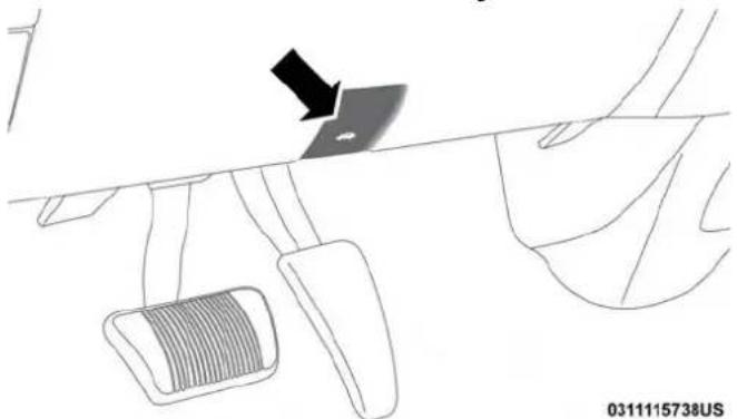
natural_image
Diagram of a car's steering wheel and dashboard with a black arrow indicating the lever (no text or symbols present)HoodRelease

- Reach into the opening beneath the center of the hood and push the safety latch lever to the left to release it, before raising the hood.
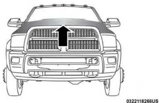
natural_image
Front view of a pickup truck with grille grating and side-mounted sensors (no text or symbols visible)SafetyLatchLocation
GETTING TO KNOW YOUR VEHICLE 101
To Close The Hood
Lower the hood to approximately 12 inches (30 cm) from the engine compartment and drop it. Make sure that the hood is completely closed.
WARNING!
Besurethehoodisfullylatchedbeforedrivingyour vehicle.Ifthehoodisnotfullylatched,itcouldopen whenthevehicleisinmotionandblockyourvision. Failuretofollowthiswarningcouldresultinserious injuryordeath.
CAUTION!
Topreventpossibledamage, donotslamthehoodto closeit. Useafirmdownwardpushatthefrontcenter ofthehoodtoensurethatbothlatchesengage.
GARAGE DOOR OPENER — IF EQUIPPED
HomeLink replaces up to three hand-held transmitters that operate devices such as garage door openers, motorized gates, lighting or home security systems. The HomeLink unit is powered by your vehicles 12 Volt battery.
The HomeLink buttons that are located in the overhead console designate the three different HomeLink channels.
text_image
Diagram showing a house with five vertical bars, each containing black and white symbols, likely representing a sequence or pattern.0449097657US
HomeLinkButtons
NOTE: HomeLink is disabled when the Vehicle Security Alarm is active.
WARNING!
- Yourmotorizeddoororgatewillopenandclose whileyouaretrainingtheuniversaltransceiver.Do nottrainthetransceiverifpeople,petsorother objectsareinthepathofthedoororgate.Onlyuse thistransceiverwithagaragedooropenerthathasa "stopandreverse"featureasrequiredbyFederal safetystandards.Thisincludesmostgaragedoor openermodelsmanufacturedafter1982.Donotusea garagedooropenerwithoutthesesafetyfeatures. Calltoll-free1-800-355-3515or,ontheInternetat www.HomeLink.comforsafetyinformationorassistance.
- Vehicleexhaustcontainscarbonmonoxide,adangerousgas.Donotrunyourvehicleinthegaragewhile trainingthetransceiver.Exhaustgascancauseseriousinjuryordeath.
NOTE: Only use this transceiver with a garage door opener that has a “stop and reverse” feature as required by federal safety standards. This includes most garage door opener models manufactured after 1982. Do not use a garage door opener without these safety features. Call
toll-free 1-800-355-3515 or, on the Internet at HomeLink.com for safety information or assistance.

DEALER ePROCESS
Before You Begin Programming HomeLink
Ensure your vehicle is parked outside of the garage before you begin programming.
For efficient programming and accurate transmission of the radio-frequency signal it is recommended that a new battery be placed in the hand-held transmitter of the device that is being programmed to the HomeLink system.
To erase the channels place the ignition in the ON/RUN position and push and hold the two outside HomeLink buttons (I and III) for up to 20 seconds. The instrument cluster display will display "CLEARING CHANNELS."
Release the buttons when "CHANNELS CLEARED" appears on the display.
NOTE:
- For vehicle's equipped with Keyless Enter-N-Go, place the ignition in the RUN position with the Engine ON. Make sure while programming HomeLink with the engine ON that your vehicle is outside of your garage, or that the garage door remains open at all times.
- Erasing all channels should only be performed when programming HomeLink for the first time. Do not erase channels when programming additional buttons.
- If you have any problems, or require assistance, please call toll-free 1-800-355-3515 or, on the Internet at HomeLink.com for information or assistance.
104 GETTING TO KNOW YOUR VEHICLE
Programming A Rolling Code
For programming garage door openers that were manufactured after 1995. These garage door openers can be identified by the "LEARN" or "TRAIN" button located where the hanging antenna is attached to the garage door opener. It is NOT the button that is normally used to open and close the door. The name and color of the button may vary by manufacturer.
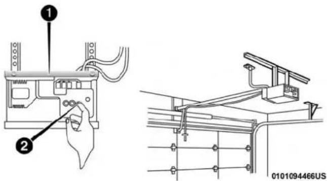
text_image
Technical diagram showing installation steps of a device with labeled components and connection detailsTrainingTheGarageDoorOpener
1 — Door Opener
2 — Training Button
- Turn the ignition switch to the ON/RUN position.
NOTE: For vehicles equipped with Keyless Enter-N-Go, place the ignition in the RUN position with the Engine ON. Make sure while programming HomeLink with the engine ON that your vehicle is outside of your garage, or that the garage door remains open at all times.
- Place the hand - held transmitter 1 to 3 inches (3 to 8 cm) away from the HomeLink button you wish to program.
- Push and hold the HomeLink button you want to program while you push and hold the hand - held transmitter button.
- Continue to hold both buttons until the instrument cluster display changes from "CHANNEL # TRAINING" to "CHANNEL # TRAINED," then release both buttons.
NOTE:
- It may take up to 30 seconds or longer in some cases for the channel to train.
- If "DID NOT TRAIN" appears in the Instrument Cluster Display, repeat from Step 2.

DEALER ePROCESS
- At the garage door opener motor (in the garage), locate the "LEARN" or "TRAINING" button. This can usually be found where the hanging antenna wire is attached to the garage door opener/device motor. Firmly push and release the "LEARN" or "TRAINING" button. On some garage door openers/devices there may be a light that blinks when the garage door opener/device is in the LEARN/TRAIN mode.
NOTE: You have 30 seconds in which to initiate the next step after the LEARN button has been pushed.
- Return to the vehicle and push the programmed HomeLink button twice (holding the button for two seconds each time). The instrument cluster display will show "CHANNEL # TRANSMIT." If the garage door opener/device activates, programming is complete.
NOTE: If the garage door opener/device does not activate, push the button a third time (for two seconds) to complete the training.
To program the remaining two HomeLink buttons, repeat each step for each remaining button. DO NOT erase the channels.
ReprogrammingASingleHomeLinkButton(Rolling Code)
To reprogram a channel that has been previously trained, follow these steps:
- Cycle the ignition to the ON/RUN position.
- Push and hold the desired HomeLink button until the indicator light begins to flash after 20 seconds. Donot releasethebutton.
- Withoutreleasingthebuttonproceed with "Programming A Rolling Code" step 2 and follow all remaining steps.
Programming A Non-Rolling Code
For programming Garage Door Openers manufactured before 1995.
- Turn the ignition switch to the ON/RUN position.
- Place the hand - held transmitter 1 to 3 inches (3 to 8 cm) away from the HomeLink button you wish to program.
- Push and hold the HomeLink button you want to program while you push and hold the hand - held transmitter button.

106 GETTING TO KNOW YOUR VEHICLE
- Continue to hold both buttons until the instrument cluster display changes from "CHANNEL # TRAINING" to "CHANNEL # TRAINED," then release both buttons.
NOTE:
- It may take up to 30 seconds or longer in some cases for the channel to train.
-
If the instrument cluster display shows "DID NOT TRAIN", repeat from Step 2.
-
Push and hold the programmed HomeLink button. The instrument cluster display will display "CHANNEL #TRANSMIT." If the garage door opener/device activates, programming is complete.
To program the remaining two HomeLink buttons, repeat each step for each remaining button. DO NOT erase the channels.
ReprogrammingASingleHomeLinkButton (Non-RollingCode)
To reprogram a channel that has been previously trained, follow these steps:
-
Cycle the ignition to the ON/RUN position.
-
Push and hold the desired HomeLink button until the indicator light begins to flash after 20 seconds. Donot releasethebutton.
- Withoutreleasingthebuttonproceed with "Programming A Non-Rolling Code" step 2 and follow all remaining steps.
Canadian/Gate Operator Programming
For programming transmitters in Canada/United States that require the transmitter signals to “time-out” after several seconds of transmission.
Canadian radio frequency laws require transmitter signals to time-out (or quit) after several seconds of transmission – which may not be long enough for HomeLink to pick up the signal during programming. Similar to this Canadian law, some U.S. gate operators are designed to time-out in the same manner.
It may be helpful to unplug the device during the cycling process to prevent possible overheating of the garage door or gate motor.
- Turn the ignition switch to the ON/RUN position.

NOTE: For vehicle's equipped with Keyless Enter-N-Go, place the ignition in the RUN position with the Engine ON. For vehicle's equipped with Keyless Enter-N-Go, place the ignition in the RUN position with the Engine ON. Make sure while programming HomeLink with the engine ON that your vehicle is outside of your garage, or that the garage door remains open at all times.
- Place the hand - held transmitter 1 to 3 inches (3 to 8 cm) away from the HomeLink button you wish to program.
- Push and hold the HomeLink button while you push and release ("cycle"), your hand - held transmitter every two seconds.
- Continue to hold both buttons until the instrument cluster display changes from "CHANNEL # TRAINING" to "CHANNEL # TRAINED," then release both buttons.
NOTE:
- It may take up to 30 seconds or longer in some cases for the channel to train.
-
If the instrument cluster display shows "DID NOT TRAIN", repeat from Step 2.
-
Push and hold the programmed HomeLink button. The instrument cluster display will display "CHANNEL # TRANSMIT." If the device is plugged in and activates, programming is complete.
If you unplugged the garage door opener/device for programming, plug it back in at this time.
ReprogrammingASingleHomeLinkButton (Canadian/GateOperator)
To reprogram a channel that has been previously trained, follow these steps:
- Turn the ignition switch to the ON/RUN position.
NOTE: For vehicle's equipped with Keyless Enter-N-Go, place the ignition in the RUN position with the Engine ON. For vehicle's equipped with Keyless Enter-N-Go, place the ignition in the RUN position with the Engine ON. Make sure while programming HomeLink with the engine ON that your vehicle is outside of your garage, or that the garage door remains open at all times.
- Push and hold the desired HomeLink button until the instrument cluster display shows "CHANNEL # TRAINING" Donotreleasethebutton.
108 GETTING TO KNOW YOUR VEHICLE
- Withoutreleasingthebuttonproceed with "Canadian/ Gate Operator Programming" Step 2 and follow all remaining steps.
Using HomeLink
To operate, push and release the programmed HomeLink button. Activation will now occur for the programmed device (i.e. garage door opener, gate operator, security system, entry door lock, home/office lighting, etc.) The hand-held transmitter of the device may also be used at any time.
Security
It is advised to erase all channels before you sell or turn in your vehicle.
To erase the channels press and hold the two outside HomeLink buttons (I and III) for up 20 seconds. The instrument cluster display will display "CLEARING CHANNELS." Release the buttons when the instrument cluster display shows "CHANNELS CLEARED."
The HomeLink Universal Transceiver is disabled when the Vehicle Security Alarm is active.
Troubleshooting Tips
If you are having trouble programming HomeLink, here are some of the most common solutions:
- Replace the battery in the Garage Door Opener handheld transmitter.
- Push the LEARN button on the Garage Door Opener to complete the training for a Rolling Code.
- Did you unplug the device for programming and remember to plug it back in?
If you have any problems, or require assistance, please call toll-free 1-800-355-3515 or, on the Internet at HomeLink.com for information or assistance.
WARNING!
- Vehicleexhaustcontainscarbonmonoxide,adangerousgas.Donotrunyourvehicleinthegaragewhile programmingthetransceiver.Exhaustgascancause seriousinjuryordeath.
- Yourmotorizeddoororgatewillopenandclose while you are programming the universal transceiver.Donotprogramthetransceiverifpeople,pets
WARNING!(Continued)
orotherobjectsareinthepathofthedoororgate. Onlyusethistransceiverwithagaragedooropener thathasa"stopandreverse"featureasrequiredby Federalsafetystandards.Thisincludesmostgarage dooropenermodelsmanufacturedafter1982.Donot useagaragedooropenerwithoutthesesafetyfeatures.Calltoll-free1-800-355-3515or,ontheInternet atHomeLink.comforsafetyinformationorassistance.
General Information
The following regulatory statement applies to all Radio Frequency (RF) devices equipped in this vehicle:
This device complies with Part 15 of the FCC Rules and with Industry Canada license-exempt RSS standard(s). Operation is subject to the following two conditions:
- This device may not cause harmful interference, and
- This device must accept any interference received, including interference that may cause undesired operation.
NOTE: Changes or modifications not expressly approved by the party responsible for compliance could void the user's authority to operate the equipment.
INTERNAL EQUIPMENT
Storage
GloveCompartment
The glove compartment is located on the passenger side of the instrument panel and features both an upper and lower storage area.

text_image
GloveCompartment 0322115779US1 — Upper Glove Compartment
2 — Lower Glove Compartment

110 GETTING TO KNOW YOUR VEHICLE
To open the upper glove compartment, push upward on the handle release. The glove compartment door will automatically open.

natural_image
Interior view of a car dashboard with air vent and rear-mounted screens (no text or symbols visible)UpperGloveCompartment
To open the lower glove compartment, pull the release handle.

natural_image
Interior view of a car showing the rear intake compartment with a plastic tray and side compartments (no text or symbols)LowerGloveCompartment
DoorStorage
FrontDoorStorage—IfEquipped
Storage areas and bottle holders (driver's side only) are located in the door trim panels.

natural_image
Interior view of a car showing dashboard and ventricles with arrows indicating flow direction (no text or symbols)FrontDoorStorage
RearDoorStorage—IfEquipped
Storage compartments are located in both the driver and passenger rear door trim panels.

natural_image
Diagram of a car interior showing the backrest door and side panel, with arrows indicating direction (no text or symbols)RearDoorStorage
112 GETTING TO KNOW YOUR VEHICLE
CenterStorageCompartment—IfEquipped
The center storage compartment is located between the driver and passenger seats. The storage compartment provides an armrest and contains both and upper and lower storage area.
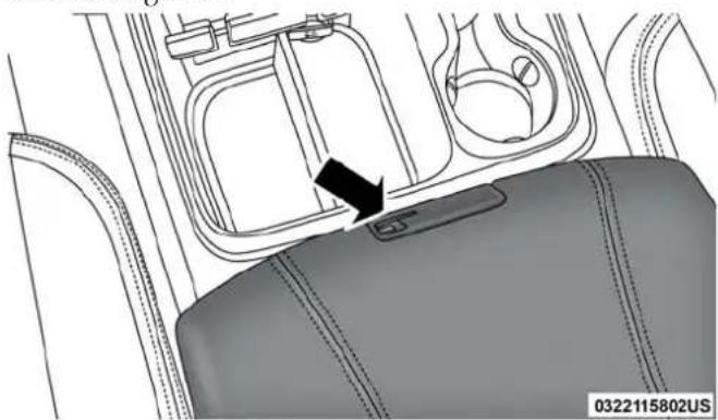
natural_image
Interior view of a car intake canal with a black arrow pointing to the intake compartment (no text or symbols visible)CenterStorageCompartment
WARNING!
- Thisarmrestisnotaseat.Anyoneseatedonthe armrestcouldbeseriouslyinjuredduringvehicle operation,oracollision.Onlyusethecenterseating positionwhenthearmrestisfullyupright.
- Inacollision, the latch may open if the total weight of the items stored exceeds about 10 lbs (4.5 kg). These items could be thrown about endangering occupants of the vehicle. Items stored should not exceed at total of 10 lbs (4.5 kg).
GETTING TO KNOW YOUR VEHICLE 113
Pull on the upper handle on the front of the armrest to raise the cover. The upper storage area contains a USB power outlet that can be used to power small electrical devices, refer to "Electrical Power Outlets" for further information.
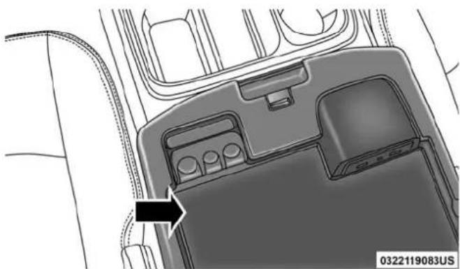
natural_image
Interior view of a vehicle dashboard with control panel and buttons, showing no visible text or symbolsUpperStorageCompartment
With the upper lid closed, pull on the lower handle to open the lower storage bin.
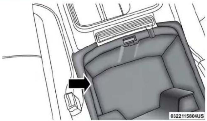
natural_image
Interior view of a vehicle dashboard with no visible text or symbolsLowerStorageBin
WARNING!
Donotoperatethisvehiclewithaconsolecompartmentlidintheopenposition.Drivingwiththeconsole compartmentlidopenmayresultininjuryinacollision.
114 GETTING TO KNOW YOUR VEHICLE
The center console is equipped with a front storage bin located next to the cupholders. This storage bin may be equipped with a manual sliding top door.
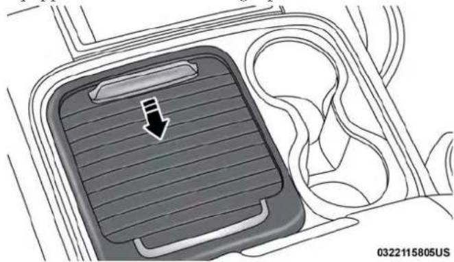
natural_image
Diagram of a car intake tray with a downward arrow indicating flow or direction, enclosed in a vehicle gear (no text or symbols)FrontStorageBinWithDoor—IfEquipped
SeatbackStorage
Located in the back of both the driver and passenger front seats are pockets that can be used for storage.
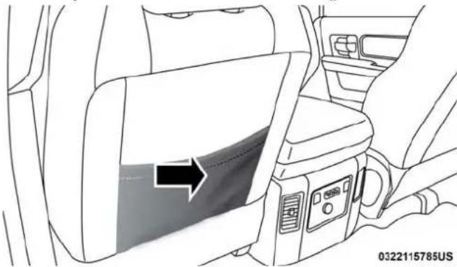
natural_image
Interior view of a car showing seatbelt and dashboard (no text or symbols)Driver'sSideSeatbackStorage

SecondRowIn-FloorStorageBin—IfEquipped
In-floor storage bins are located in front of the second row seats and can be used for extra storage. The storage bins have removable liners that can be easily removed for cleaning.
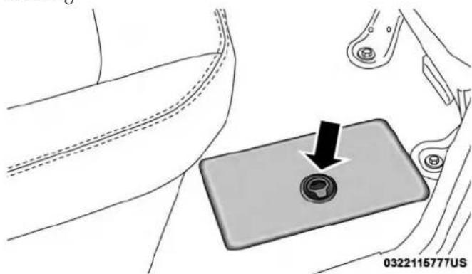
natural_image
Mechanical switch component with a black arrow pointing to a circular button, no text or symbols presentIn-FloorStorageBinAndLatch
To open in-floor storage bin, lift upward on the handle of the latch and open the lid.
NOTE: The front seat may have to be moved forward to fully open the lid.
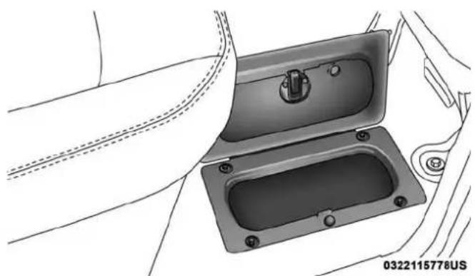
natural_image
Technical illustration of a mechanical component with mounting holes and a side panel (no text or symbols)OpenedStorageBin
116 GETTING TO KNOW YOUR VEHICLE
StorageBin(RegularCab)
The storage bin is located behind the front seats and runs the length of the cab.
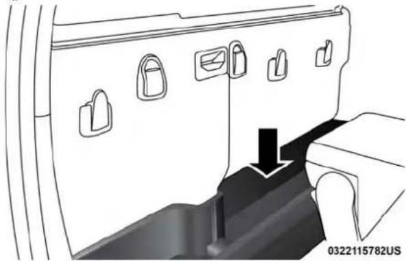
natural_image
Technical diagram of a vehicle door frame with lock symbols and a black arrow indicating a component (no text or labels)StorageBin
FoldFlatLoadFloor—IfEquipped
Quad Cab and Crew Cab models with a 60/40 rear seat may be equipped with a folding load floor.
WARNING!
Donotoperatethevehiclewithlooseitemsstoredon theloadfloor. Whiledrivingorinanaccidentyoumay experienceabruptstopping,rapidacceleration,or sharpturns. Looseobjectsstoredontheloadfloormay movearoundwithforceandstrikeoccupants,resulting inseriousorfatalinjury.
UnfoldingTheLoadFloor/QuadCab
- Lift the 60/40 seat cushion(s) to the upward position.

natural_image
Interior view of a car showing a vehicle seat with a highlighted internal component (no text or symbols visible)UnfoldingTheLoadFloor

- Grasp the knob on the load floor and lift the knob until the load floor unfolds into position.

natural_image
Interior view of a car showing the rear seat and side seats (no text or symbols visible)LoadFloorInOpenPosition
- Reverse the procedure to store the load floor.
UnfoldingTheLoadFloor/CrewCab
- Lift the 60/40 seat cushion(s) to the upward position.

natural_image
Interior view of a vehicle air intake bay with directional arrows indicating flow or movement (no text or symbols)LoadFloorLegsInStowedPosition
118 GETTING TO KNOW YOUR VEHICLE
- Unfold both the legs using the straps.
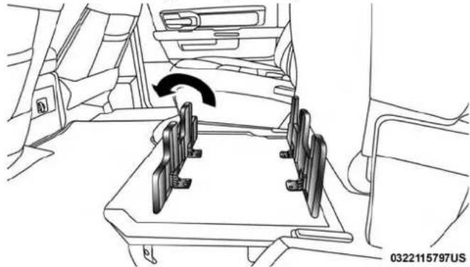
natural_image
Interior view of a car showing a vehicle's seat, dashboard, and steering wheel (no text or symbols visible)LoadFloorLegsInOpenedPosition
- Lift the front panel until the load floor unfolds into position.
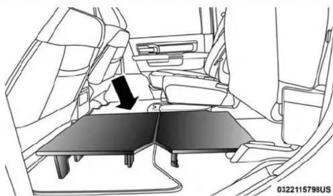
natural_image
Interior view of a car showing the rear seat, dashboard, and side table (no text or symbols visible)LoadFloorInOpenPosition
- Reverse the procedure to store the load floor.
PositioningTheLoadFloorForStorageAccessUnder TheSeat
- Lift the 60/40 seat cushion(s) to the upward position.
- Unsnap the securing snap located at either side of the load floor.
- Lift the load floor up to access storage under the load floor.
WARNING!
Donotdrivewiththeloadfloorintheupposition. Whenstoppingfastorinanaccident,theloadfloor couldmovetothedownpositioncausingserious injury.
QuadCab—IfEquipped

natural_image
Line drawing of a car seatbelt mechanism with no visible text or symbolsLoadFloorSecuringStraps/QuadCab
120 GETTING TO KNOW YOUR VEHICLE
CrewCab—IfEquipped

natural_image
Line drawing of a car seatbelt assembly with a black arrow indicating the component (no text or symbols present)LoadFloorSecuringStraps/CrewCab
4. Reverse the procedure to put the load floor back in the secured down position before you operate the vehicle.
BelowRearSeatStorage(CrewCab/QuadCab)
The Crew Cab and Quad Cab models provide additional storage under the rear seats. Lift the seats to access the storage compartment.
To open the storage compartments, unsnap the securing snap located at either side of the load floor and lift upward on the fold flat lid.
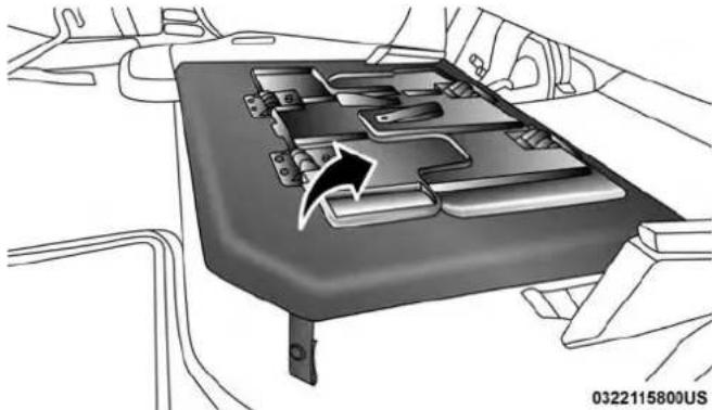
natural_image
Interior view of a car showing the rear vent and dashboard (no text or symbols visible)CrewCabStorage
NOTE: For more information on storage and the fold flat floor, refer to "Fold Flat Load Floor" in this section.

Cupholders
FrontSeatCupholders
For vehicles equipped with bucket seats, two cupholders are located next to the center console storage bin.
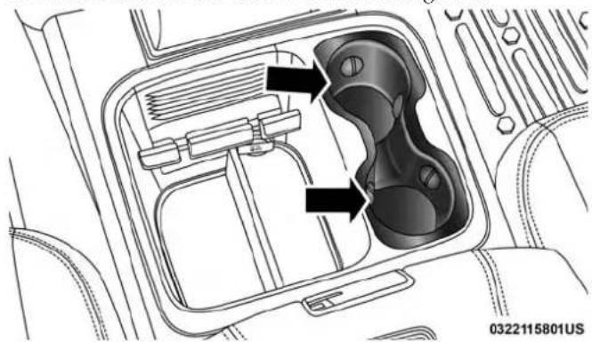
natural_image
Technical diagram of a car interior showing internal compartments and structural elements (no text or labels)FrontCupholdersForBucketSeats
VehiclesEquippedWith40/20/40Seats
The cupholders are located on the backside of the center portion of the front seat (20). Fold down the center section of the front seat to gain access to the cupholders.
RearCupholders—IfEquipped
Some vehicles are equipped with rear cupholders located in the center armrest.

natural_image
Interior view of a car showing the backrest seat, dashboard, and rear seats with a black arrow pointing to the side panel (no text or symbols present)RearArmrestCupholder
122 GETTING TO KNOW YOUR VEHICLE
Some vehicles may be equipped with a rear cupholder that consists of two cup wells for rear passenger convenience.
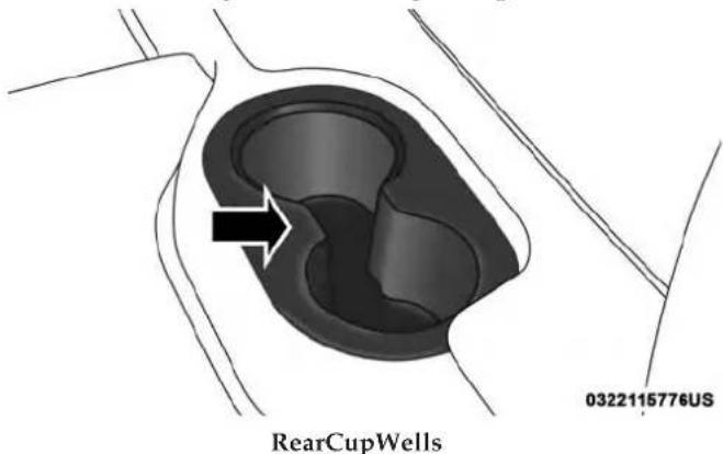
text_image
RearCupWells 0322115776USElectrical Power Outlets
The auxiliary 12 Volt (13 Amp) power outlets can provide power for in-cab accessories designed for use with the standard "cigar lighter" plug. The 12 Volt power outlets and USB Port (Charge Only) have a cap attached to the outlet indicating "12V DC," together with either a key symbol, battery symbol, or USB symbol.
A key symbol indicates that the key must be in the ON/RUN or ACC positions for the outlet to provide power. The battery symbol indicates that the outlet is connected to the battery, and can provide power at all times.
CAUTION!
- Donotexceedthemaximumpowerof160Watts(13 Amps)at12Volts.Ifthe160Watts(13Amps)power ratingisexceeded,thefuseprotectingthesystem willneedtobereplaced.
- Poweroutletsaredesignedforaccessoryplugsonly. Donotinsertanyotherobjectinthepoweroutletsas thiswilldamagetheoutletandblowthefuse. Improperuseofthepoweroutletcancausedamage notcoveredbyyourNewVehicleLimitedWarranty.
The auxiliary power outlets can be found in the following locations:
- Lower left and lower right of the center stack when equipped with a bench seat.
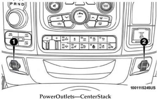
text_image
PRND 1 2 1001115245US PowerOutlets—CenterStack1 — Power Outlet
2 — USB Port (Charge Only)
- Center console when equipped with bucket seats.

text_image
PowerOutlet—CenterConsole 1001115250US124 GETTING TO KNOW YOUR VEHICLE
- Rear of the center console storage compartment — Quad Cab or Crew Cab.

text_image
1001115240USPowerOutlet—RearCenterConsole
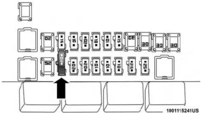
text_image
02 51 00 20 01 10 15 0E 30 30 30 52 204 024 104 104 104 104 104 104 104 104 104 104 104 104 104 104 104 104 104 104 104 104 104 104 104 104 104 180115241USPowerOutlet—RearCenterConsoleFuse
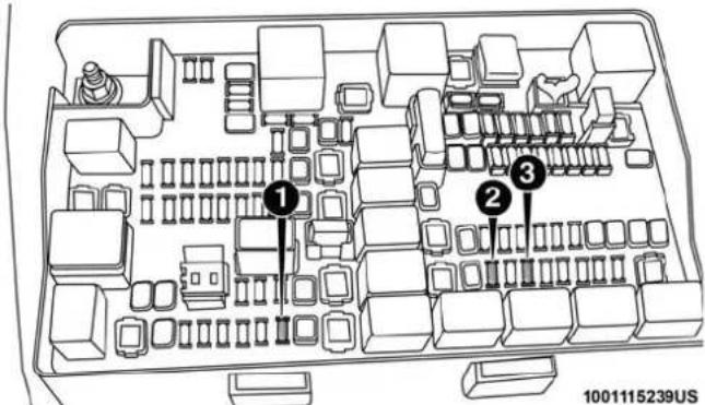
text_image
1 2 3 1001115239USPowerOutletFuseLocations
1 — F104 Fuse 20 A Yellow Power Outlet Center Console Bin / USB Port (Charge Only)
2 — F90-F91 Fuse 20 A Yellow Power Outlet Rear Center Console
3 — F93 Fuse 20 A Yellow Cigar Lighter Instrument Panel
When the vehicle is turned off, be sure to unplug any equipment as to not drain the battery of the vehicle. All accessories connected to the outlet(s) should be removed or turned off when the vehicle is not in use to protect the battery against discharge.
WARNING!
Toavoidseriousinjuryordeath:
- Onlydevicesdesignedforuseinthistypeofoutlet shouldbeinsertedintoany12Voltoutlet.
• Donottouchwithwethands. - Closethelidwhennotinuseandwhiledrivingthe vehicle.
- If this outletismishandled, it may cause an electric shock and failure.
CAUTION!
- Manyaccessoriesthatcanbepluggedindrawpower fromthevehicle'sbattery,evenwhennotinuse(i.e., cellularphones,etc.).Eventually,ifpluggedinlong enough,thevehicle'sbatterywilldischargesufficientlytodegradebatterylifeand/orpreventthe enginefromstarting.
- Accessories that draw higher power (i.e., coolers, vacuum cleaners, lights, etc.), will discharge the battery even more quickly. Only us these intermittently and with greater caution.
CAUTION!(Continued)
- Aftertheuseofhighpowerdrawaccessories,orlong periodsofthevehiclenotbeingstarted(withaccessoriesstillpluggedin),thevehiclemustbedrivena sufficientlengthoftimetoallowthegeneratorto rechargethevehicle'sbattery.
Cigar Lighter And Ash Receiver — If Equipped
A removable cigar lighter and ash receiver are available. For vehicles with a bench seat, the cup holder tray can be used to hold the ash receiver.
Power Inverter — If Equipped
A 115 or 230 Volt (150 Watts Maximum) outlet is located on the center stack of the instrument panel, to the right of the radio. This outlet can power cellular phones, electronics and other low power devices requiring power up to 150 Watts. Certain high-end video game consoles will exceed this power limit, as will most power tools.
The power inverter is designed with built-in overload protection. If the power rating of 150 Watts is exceeded, the power inverter will automatically shut down. Once the electrical device has been removed from the outlet the inverter should automatically reset.
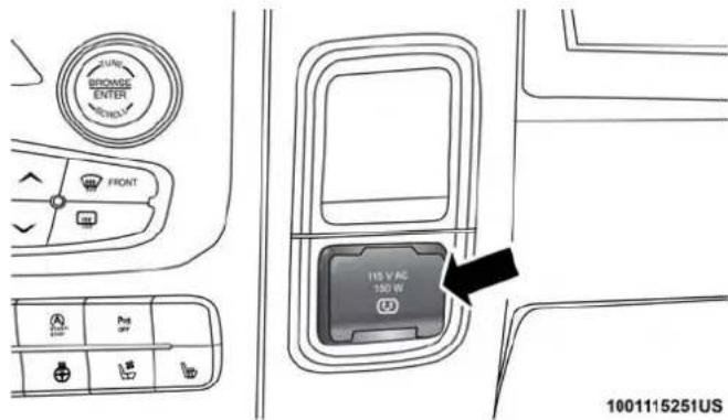
text_image
BROWSE ENTER FRONT 115 V AC 150 W 1001115251USPowerInverterOutlet
To turn on the power outlet, simply plug in the device. The outlet automatically turns off when the device is unplugged.
NOTE:
- The Power Inverter will only turn on if the ignition is in the ACC or ON/RUN position.
- Due to built-in overload protection, the power inverter will shut down if the power rating is exceeded.

WARNING!
Toavoidseriousinjuryordeath:
- Donotinsertanyobjectsintothereceptacles.
- Donottouchwithwethands.
•Closethelidwhennotinuse. - If this outletismishandled, it may cause an electric shock and failure.
Auxiliary Switches — If Equipped
There can be up to five auxiliary switches located in the lower switch bank of the instrument panel which can be used to power various electronic devices and PTO (Power Take Off) – If Equipped. If Power Take Off is equipped, it will take the place of the fifth Auxiliary switch. Connections to the switches are found under the hood in the connectors attached to the auxiliary Power Distribution Center.
You have the ability to configure the functionality of the auxiliary switches via the instrument cluster display. All switches can now be configured for setting the switch type operation to latching or momentary, power source of either battery or ignition, and ability to hold last state across key cycles.
NOTE: Holding last state conditions are met when switch type is set to latching and power source is set to ignition.
For further information on using the auxiliary switches, please refer to the Ram Body Builders Guide by accessing www.rambodybuilder.com and choosing the appropriate links.

GETTING TO KNOW YOUR INSTRUMENT PANEL
CONTENTS
■BASE INSTRUMENT CLUSTER....130
□Base Instrument Cluster Descriptions .....130
■PREMIUM INSTRUMENT CLUSTER....132
□Premium Instrument Cluster Descriptions . . . . .132
■INSTRUMENT CLUSTER DISPLAY....134
□Instrument Cluster Display Controls .....135
□Display Menu Screens....137
□Oil Life Reset. . . . . . . . . . . . . . . . . . . . . . . . . . . . . . . . . . . . . . . . . . . . . . . . . . . . . . . . 139
□Display Messages....140
□Display Menu Items....142
☐Battery Saver On/Battery Saver Mode Message — Electrical Load Reduction Actions — If Equipped....150
■WARNING LIGHTS AND MESSAGES....152
□Red Warning Lights....152
□Yellow Warning Lights....155
□Yellow Indicator Lights. . . . . . . . . . . . . . . . . . . . . . . . . . . . . . . . . . . . . . . . . . . . . . . . . . 159
□Green Indicator Lights....160
□White Indicator Lights....161
□Blue Indicator Lights....161
■ONBOARD DIAGNOSTIC SYSTEM — OBD II . . .161
□Onboard Diagnostic System (OBD II) Cybersecurity....162
■EMISSIONS INSPECTION AND MAINTENANCE PROGRAMS....163
130 GETTING TO KNOW YOUR INSTRUMENT PANEL
BASE INSTRUMENT CLUSTER

text_image
① ② ③ ④ 040117817US ⑤ P R N D BRAKE ⑥ ⑦ ⑧ ⑨ ⑩ ⑪ ⑫ ⑬ ⑭ ⑮ ⑯ ⑰ ⑱ ⑲ ⑳ ⑴ ⑵ ⑶ ⑷ ⑧ ⑨ ⑩ ⑪ ⑫ ⑬ ⑭ ⑮ ⑯ ⑰ ⑱ ⑲ ⑳ ㉑ ㉒ ㉓ ㉔ ㉕ ㉖ ㉗ ㉘ ㉙ ㉚ ㉛ ㉜ ㉝ ㉞ ㉟ ㉳ ㉟ ㉟ ㉟ ㉟ ㉟BaseInstrumentClusters
Base Instrument Cluster Descriptions
1. Tachometer
- Indicates the engine speed in revolutions per minute (RPM x 1000).
2. Instrument Cluster Display
- When the appropriate conditions exist, this display shows the instrument cluster display messages. Refer to "Instrument Cluster Display" in "Getting To Know Your Instrument Panel" for further information.
3. Speedometer
- Indicates vehicle speed.
4. Fuel Gauge
- The pointer shows the level of fuel in the fuel tank when the ignition is in the ON/RUN position.
- The fuel pump symbol points to the side of the vehicle where the fuel door is located.
5. Temperature Gauge
- The temperature gauge shows engine coolant temperature. Any reading within the normal range indicates that the engine cooling system is operating satisfactorily.
- The gauge pointer will likely indicate a higher temperature when driving in hot weather, up mountain grades, or when towing a trailer. It should not be allowed to exceed the upper limits of the normal operating range.
WARNING!
Ahotenginecoolingsystemisdangerous. Youor otherscouldbebadlyburnedbysteamorboiling coolant. Youmaywanttocallanaauthorizeddealerfor serviceifyourvehicleoverheats. If youdecidetolook underthehoodyourself, see "ServicingAndMaintenance." FollowthewarningsundertheCoolingSystem PressureCapparagraph.
CAUTION!
Drivingwithahotenginecoolingsystemcoulddamageyourvehicle.Ifthetemperaturegaugereads"H,"pulloverandstopthevehicle.Idlethevehiclewiththeairconditionerturnedoffuntilthepointerdropsbackintothenormalrange.Ifthepointerremainsonthe"H,"turntheengineoffimmediatelyandcallanauthorizeddealerforservice.
132 GETTING TO KNOW YOUR INSTRUMENT PANEL
PREMIUM INSTRUMENT CLUSTER
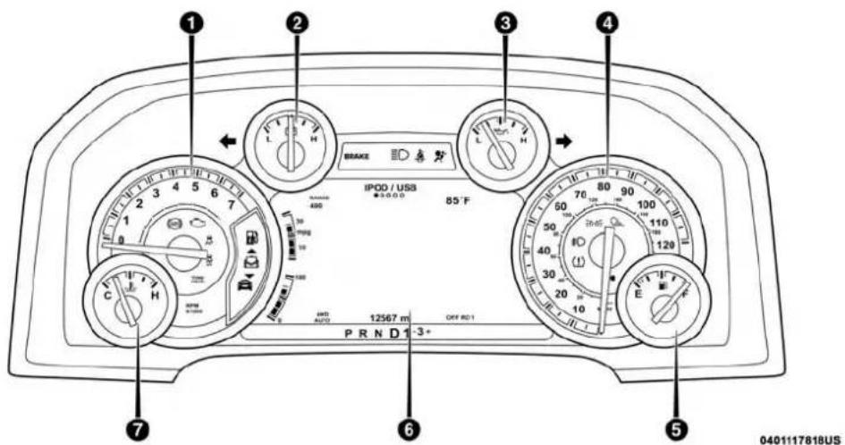
text_image
IPOD / USB 85°F PRND1 -3+ 0401117818USPremiumInstrumentClusters
Premium Instrument Cluster Descriptions
1. Tachometer
- Indicates the engine speed in revolutions per minute (RPM x 1000).
2. Voltmeter
- When the engine is running, the gauge indicates the electrical system voltage. The pointer should stay within the normal range if the battery is charged. If the pointer moves to either extreme left or right and remains there during normal driving, the electrical system should be serviced.

NOTE: The voltmeter may show a gauge fluctuation at various engine temperatures. This cycling operation is caused by the post-heat cycle of the intake manifold heater system. The number of cycles and the length of the cycling operation is controlled by the engine control module. Post-heat operation can run for several minutes, and then the electrical system and voltmeter needle will stabilize.
3. Oil Pressure Gauge
- The pointer should always indicate some oil pressure when the engine is running. A continuous high or low reading under normal driving conditions may indicate a lubrication system malfunction. Immediate service should be obtained from an authorized dealer.
4. Speedometer
- Indicates vehicle speed.
5. Fuel Gauge
- The pointer shows the level of fuel in the fuel tank when the ignition is in the ON/RUN position.
- The fuel pump symbol points to the side of the vehicle where the fuel door is located.
6. Instrument Cluster Display
- When the appropriate conditions exist, this display shows the instrument cluster display messages. Refer to "Instrument Cluster Display" in "Getting To Know Your Instrument Panel" for further information.
7. Temperature Gauge
- The temperature gauge shows engine coolant temperature. Any reading within the normal range indicates that the engine cooling system is operating satisfactorily.
- The gauge pointer will likely indicate a higher temperature when driving in hot weather, up mountain grades, or when towing a trailer. It should not be allowed to exceed the upper limits of the normal operating range.
WARNING!
Ahotenginecoolingsystemisdangerous. Youor otherscouldbebadlyburnedbysteamorboiling coolant. Youmaywanttocallanaauthorizeddealerfor serviceifyourvehicleoverheats. Ifyoudecidetolook underthehoodyourself, see "ServicingAndMaintenance." FollowthewarningsundertheCoolingSystem PressureCapparagraph.
CAUTION!
Drivingwithahotenginecoolingsystemcoulddamageyourvehicle.Ifthetemperaturegaugereads"H,"pulloverandstopthevehicle.Idlethevehiclewiththeairconditionerturnedoffuntilthepointerdropsbackintothenormalrange.Ifthepointerremainsonthe"H,"turntheengineoffimmediatelyandcallanauthorizeddealerforservice.
INSTRUMENT CLUSTER DISPLAY
Your vehicle will be equipped with an instrument cluster display, which offers useful information to the driver. With the ignition in the STOP/OFF mode, opening/closing of a door will activate the display for viewing, and display the total miles, or kilometers, in the odometer. Your instrument cluster display is designed to display important information about your vehicle's systems and features. Using a driver interactive display located on the instrument panel, your instrument cluster display can show you how systems are working and give you warnings when they are not. The steering wheel mounted controls allow you to scroll through the main menus and submenus. You can access the specific information you want and make selections and adjustments.
Instrument Cluster Display Controls
The instrument cluster display features a driver-interactive display that is located in the instrument cluster.
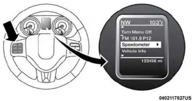
text_image
NW 103°F Turn Menu Off FM 101.9 P12 Speedometer Vehicle Info 123456 mi 0402117827USBaseInstrumentClusterDisplay
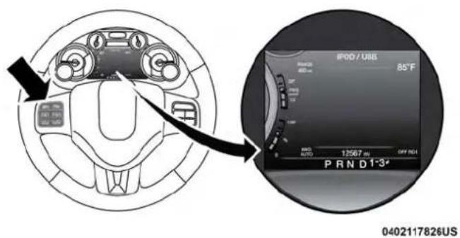
text_image
IP00 / USB 85°F AUTO 12567 ms OFF RGB PRND1-3* 0402117826USPremiumInstrumentClusterDisplay
The instrument cluster display menu items may consist of the following:
•Speedometer
- Vehicle Info
•Fuel Economy Info
- Trip A
- Trip B
•Audio
- Trailer Tow

136 GETTING TO KNOW YOUR INSTRUMENT PANEL
- Stored Messages
- Screen Setup
- Vehicle Settings (Not equipped with a Uconnect touchscreen radio)
The system allows the driver to select information by pushing the following instrument cluster display control buttons located on the left side of the steering wheel:

text_image
VR Δ Δ Δ0402117821US
InstrumentClusterDisplayControlButtons
- UpArrowButton
△ Push and release the uparrow button to scroll upward through the main menu items, submenu screen, and vehicle settings.
-DownArrowButton
Push and release the down arrow button to scroll downward through the main menu items, sub-menu screen, and vehicle settings.
•RightArrowButton
Push and release the rightarrow button to access/select the information screens or sub-menu screens of a main menu item. Push and hold the RIGHT arrow button for two seconds to set displayed/selected features that can be reset.
- LeftArrowButton
Push and release the left arrow button to access/ select the information screens, submenu screens of a main menu item, or to return to the main menu.
Display Menu Screens

text_image
1 2 3 4 5 6 7 8 9 10 11 12 13 14 15 16 17 18 19 20 21 22 23 24 25 26 27 28 29 30 31 32 33 34 35 36 37 38 39 40 41 42 43 44 45 46 47 48 49 50 51 52 53 54 55 56 57 58 59 60 61 62 63 64 65 66 67 68 69 70 71 72 73 74 75 76 77 78 79 80 81 82 83 84 85 86 87 88 89 90 91 92 93 94 95 96 97 98 99 1000402117825US
BaseInstrumentClusterDisplay
The instrument cluster display screens are located in the center portion of the cluster and consists of seven sections:
1. CompassDisplay
Displays the current direction. Refer to "Uconnect Settings" in "Multimedia" for further information.
GETTING TO KNOW YOUR INSTRUMENT PANEL 137
2.TemperatureDisplay
Displays the outside temperature in Celsius or Fahrenheit.
3.MainScreen
Displays main menu, submenus, settings.
- WhiteTelltales
5.AmberTelltales
6.RedTelltales
- Audio/PhoneInformationAndSubmenuInformation
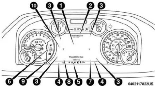
text_image
10 3 1 2 3 Press OK to Hold 13567 Press OK to Hold 13567 0402117822USPremiumInstrumentClusterDisplay
The instrument cluster display screens are located in the center portion of the cluster and consists of eight sections:
1.MainScreen
The inner ring of the display will illuminate in grey under normal conditions, yellow for non critical warnings, red for critical warnings, and white for on demand information.
2. Audio/PhoneInformation and Submenu Information
Whenever there are submenus available, the position within the submenus is shown here.
- Selectable Information (Compass, Outside Temp, Range to Empty, Trip A, Trip B, Average Fuel Economy, Trailer Trip (distance only), Trailer Brake Gain, Time)
- Telltales/Indicators
5.GearSelectorStatus
6.SelectableMenuIcons
7.4WDStatus - Selectable Gauge2(TransTemp, OilTemp, OilLife, TrailerBrake, CurrentFuelEconomy)
- Selectable Gauge1(TransTemp, OilTemp, OilLife, TrailerBrake, Currentfueleconomy)
The instrument cluster display area will normally display the main menu or the screens of a selected feature of the main menu. The main display area also displays "pop up" messages that consist of approximately 60 possible warning or information messages. These pop up messages fall into several categories:
- FiveSecondStoredMessages
When the appropriate conditions occur, this type of message takes control of the main display area for five seconds and then returns to the previous screen. Most of the messages of this type are then stored (as long as the
condition that activated it remains active) and can be reviewed from the "Messages" main menu item. As long as there is a stored message, an "i" will be displayed in the instrument cluster display's compass/outside temp line. Examples of this message type are "Right Front Turn Signal Lamp Out" and "Low Tire Pressure."
- UnstoredMessages
This message type is displayed indefinitely or until the condition that activated the message is cleared. Examples of this message type are "Turn Signal On" (if a turn signal is left on) and "Lights On" (if driver leaves the vehicle).
• UnstoredMessagesUntilRUN
These messages deal primarily with the Remote Start feature. This message type is displayed until the ignition is in the RUN state. Examples of this message type are "Remote Start Aborted - Door Ajar" and "Press Brake Pedal and Push Button to Start."
- FiveSecondUnstoredMessages
When the appropriate conditions occur, this type of message takes control of the main display area for five seconds and then returns to the previous screen. An example of this message type is "Automatic High Beams On."
Oil Life Reset
Your vehicle is equipped with an engine oil change indicator system. The “Oil Change Required” message will display in the instrument cluster display after a single chime has sounded, to indicate the next scheduled oil change interval. The engine oil change indicator system is duty cycle based, which means the engine oil change interval may fluctuate, dependent upon your personal driving style.
NOTE: Use the steering wheel instrument cluster display controls for the following procedure(s).
VehiclesEquippedWithPassiveEntry
- Without pushing the brake pedal, push the ENGINE START/STOP button and place the ignition to the ON/RUN position (do not start the engine).
- Push and release the downarrow button to scroll downward through the main menu to "Vehicle Info."
- Push and release the rightarrow button to access the "Vehicle Info" screen, then scroll up or down to select "Oil Life."
- Push and hold the rightarrow button to select "Reset".
140 GETTING TO KNOW YOUR INSTRUMENT PANEL
- Push and release the down arrow button to select "Yes," then push and release the rightarrow button to select reset of the Oil Life to 100%.
- Push and release the uparrow button to exit the instrument cluster display screen.
VehiclesNotEquippedWithPassiveEntry
- Without pushing the brake pedal, cycle the ignition to the ON/RUN position (do not start the engine).
- Push and release the downarrow button to scroll downward through the main menu to "Vehicle Info."
- Push and release the rightarrow button to access the "Vehicle Info" screen then scroll up or down to select "Oil Life."
- Push and hold the right arrow button to select "YES" by pushing the right arrow then push and release the right arrow button to select reset of the Oil Life to 100%.
- Push and release the uparrow button to exit the instrument cluster display screen.
NOTE: If the indicator message illuminates when you start the vehicle, the Oil Life indicator system did not reset. If necessary, repeat this procedure.
Display Messages
- Front Seatbelts Unbuckled
- Driver Seatbelt Unbuckled
• Passenger Seatbelt Unbuckled
•Service Airbag System - Traction Control Off
- Washer Fluid Low
- Oil Pressure Low
- Oil Change Due
- Fuel Low
•Service Antilock Brake System
•Service Electronic Throttle Control
•Service Power Steering
• Cruise Off
• Cruise Ready
• Cruise Set To XXX MPH - Tire Pressure Screen With Low Tire(s) "Inflate Tire To XX"

GETTING TO KNOW YOUR INSTRUMENT PANEL 141
•Tire Pressure Information System (TPIS)
•Service Tire Pressure System
- Parking Brake Engaged
- Brake Fluid Low
•Service Electronic Braking System
•Engine Temperature Hot
- Battery Voltage Low
•Service Electronic Throttle Control
•Lights On
• Right Turn Signal Light Out
- Left Turn Signal Light Out
- Turn Signal On
• Sound Horn With Remote Lock: Off; 1st Press; 2nd Press
- Vehicle Not In Park
•Key In Ignition
•Key In Ignition Lights On
- Remote Start Active Key To Run
- Remote Start Active Push Start Button
- Remote Start Aborted Fuel Low
- Remote Start Aborted Too Cold
- Remote Start Aborted Door Open
- Remote Start Aborted Hood Open
- Remote Start Aborted Trunk Open
- Remote Start Aborted Time Expired
- Remote Start Disabled Start To Reset
•Service Airbag System
•Service Airbag Warning Light - Driver Seatbelt Unbuckled
• Passenger Seatbelt Unbuckled
•Front Seatbelts Unbuckled - Door Open
- Doors Open
•Gear Not Available - Shift Not Allowed
- Shift to Neutral Then Drive Or Reverse
• Autostick Unavailable Service Required

142 GETTING TO KNOW YOUR INSTRUMENT PANEL
• Automatic Unavailable Use Autostick Service Req.
• Transmission Getting Hot Push Brake
•Trans. Hot Stop Safely Shift To Park Wait To Cool
• Transmission Cool Ready To Drive
• Trailer Brake Disconnected
•Service Transmission
•Service Shifter
- Engage Park Brake To Prevent Rolling
•Transmission Too Cold Idle With Engine On
- Washer Fluid Low
The Reconfigurable Telltales section is divided into the white telltales area on the right, yellow telltales in the middle, and red telltales on the left.
Display Menu Items
Push and release the upor downarrow button until the desired selectable menu icon is highlighted in the instrument cluster display.
Speedometer
Push and release the upor downarrow button until the speedometer menu item is highlighted in the instrument cluster display. Push and release the rightarrow button to cycle the display between mph and km/h.
VehicleInfo
Push and release the upor downarrow button until the Vehicle Info menu item is highlighted in the instrument cluster display. Push and release the rightarrow button to enter the submenus items of Vehicle Info. Follow the directional prompts to access or reset any of the following Vehicle Info submenu items:
- Tire Pressure
• Transmission Temp (Automatic only) - Oil Temp
•Oil Life - Fuel Filter Life
- Battery Voltage — If Equipped
• Gauge Summary — If Equipped - Engine Hours

FuelEconomy
Push and release the upor downarrow button until the Fuel Economy menu item is highlighted in the instrument cluster display. Push and Hold the rightarrow button to reset Average Fuel Economy.
• Current Fuel Economy Gauge
• Average Fuel Economy Value
- Range To Empty
• Dual Fuel Tank levels — If Equipped
- Push and release the rightarrow button to display the Fuel Tank Level submenu item. Your instrument cluster display will display the fuel levels of the Front and Rear fuel tanks. The fuel is automatically transferred from the Rear tank to the Front tank based on both tank levels. Fuel transfer is complete once the Front Fuel Level is greater than the Rear Fuel Level.
TripA/TripB
Push and release the upor downarrow button until the Trip menu item is highlighted in the instrument cluster display. Push and release the rightarrow button to enter the submenus of Trip A and Trip B. The Trip A or Trip B information will display the following:
- Distance
• Average Fuel Economy
- Elapsed Time
Push and hold rightarrow button to reset all information.
TrailerTow
Push and release the upor downarrow button until the Trailer Tow menu item is highlighted in the instrument cluster display. Push and release the rightarrow button and the next screen will display the following trailer trip information:
- Trip (trailer specific) Distance: Push and hold the right arrow button to reset the distance.
-
Trailer Brake
-
Output
• Type
•Gain
Audio
Push and release the upor downarrow button until the Audio display icon is highlighted in the instrument cluster display. Push and release the right arrow button to display the active source.

144 GETTING TO KNOW YOUR INSTRUMENT PANEL
StoredMessages
Push and release the upor downarrow button until the Messages Menu item is highlighted. This feature shows the number of stored warning messages. Pushing the right arrow button will allow you to see what the stored messages are.
When no messages are present, main menu icon will be a closed envelope.
ScreenSetupMenuItem
Push and release the upor downarrow button until the Screen Setup menu item is highlighted in the instrument cluster display. Push and release the rightarrow button to enter the Screen Setup submenu. The Screen Setup feature allows you to change what information is displayed in the instrument cluster as well as the location that information is displayed.
ScreenSetupDriverSelectableItems
UpperLeft
- None
- Compass (Default Setting)
- Outside Temp
• Time
- Range To Empty
• Average MPG
- Current MPG
- Trip A Distance
- Trip B Distance
- Trailer Trip
- Trailer Brake Gain
UpperRight
•None
- Compass
- Outside Temp (Default Setting)
• Time
- Range To Empty
• Average MPG
- Current MPG
- Trip A Distance
- Trip B Distance

GETTING TO KNOW YOUR INSTRUMENT PANEL 145
- Trailer Trip
- Trailer Brake Gain
- None
- Compass
- Outside Temp
• Time - Range To Empty
• Average MPG - Current MPG
- Trailer Brake Gain
- None
- Compass
- Outside Temp
• Time - Range To Empty
• Average MPG
LowerLeft
LowerRight
- Current MPG
- Trailer Brake Gain
- None
- Trans Temp
- Oil Temp
- Oil Life
•Fuel Filter Life (Diesel) - Battery Voltage (Diesel)
- Current MPG
- Trailer Brake
LowerGauge
Odometer
- No Decimals (Default Setting)
- Decimals
- Cancel (Default Setting)
•Ok
RestoreDefaults

Settings—IfEquipped
Personal Settings allows the driver to set and recall features when the transmission is in PARK.
Push and release the upand downbutton until Settings displays in the instrument cluster display.
Follow the prompts to display and set any of the following Vehicle Settings.
NOTE: Your vehicle may be equipped with the following settings.
- If equipped with a base radio (Non-Touchscreen) Vehicle Settings will be included in the instrument cluster display.
- If equipped with a Touchscreen radio, the Vehicle Settings will be included in the radio head unit.
| SettingNames | SettingNamesAbbreviated(Left SubmenuLayer) | Sub-Menus(RightSubmenu Layer) | |
| 1 Language Select Language English, Spanish, French, Italian, | German, Dutch | ||
| 2 Units Units U.S.; Metric | |||
| 3 ParkSense | ParkSense | Notification — Sound Only;Sound & DisplayFront Volume — Low; Medium; HighRear Volume — Low; Medium; High | |
| 4 | Tilt Mirror in Reverse | Tilt Mirror in R | On; Off |
| 5 | Rain Sensing Wipers | Auto Wipers | On; Off |
| 6 | Hill Start Assist | Hill Start Assist | On; Off |
| 7 Headlights Off Delay Lights Off Delay 0 seconds; 30 seconds; 60 seconds; 90 seconds | |||
| 8 Illuminated Approach Lights w/ Unlock 0 seconds; 30 seconds; 60 seconds; 90 seconds | |||
| 9 Headlights On with Wipers Lights w/ Wipers On; Off | |||
| 10 Automatic Highbeams Auto Highbeams On; Off | |||
| 11 Daytime Running Lights Daytime Lights | On; Off | ||
| 12 Flash Lights with Lock | Lights w/ Lock | On; Off | |
| 13 Auto Lock Doors | Auto Lock Doors | On; Off | |
| 14 Auto Unlock Doors | Auto Unlock Doors | On; Off | |
| 15 Sound Horn with Remote Start | Horn w/ Rmt Start | On; Off | |
| 16 Sound Horn with Remote Lock | Horn w/ Rmt Lock | On; Off | |
| 17 Remote Unlock Sequence | Remote Unlock | Driver Door; All Doors | |
| 18 Key Fob Linked to Memory | Key in Memory | On; Off | |
| 19 Passive Entry | Passive Entry | On; Off | |
| 20 Remote Start Comfort System | Rmt Start Comfort | On; Off | |
| 21 Easy Exit Seat | Easy Exit Seat | On; Off | |
| 22 Key-off Power Delay | Power Off Delay | Off; 45 seconds; 5 minutes; 10 minutes | |
| 23 Commercial Settings Commercial | Aux SwitchesPower Take-OffPIN SetupParkSense SetupNOTE:If the vehicle's PIN is forgotten or not known, see an authorized dealer to have the PIN reset. | ||
| 24 Aero Ride Height Mode Aero Mode On; Off | |||
| 25 Tire/Jack Mode Tire/Jack Mode On; Off | |||
| 26 Transport Mode Transport Mode On; Off | |||
| 27 | Wheel Alignment Mode | Wheel Alignment | On; Off |
| 28 | Horn w/ Remote Lower | Horn w/ Rmt Lwr | On; Off |
| 29 | Lights w/ Remote Lower | Lights w/ Rmt Lwr | On; Off |
| 30 | Trailer Select | Trailer Select | Trailer 1; Trailer 2; Trailer 3; Trailer 4 |
| 31 | Brake Type | Brake Type | Light Electric; Heavy Electric; Light EOH; Heavy EOH |
| 32 Trailer Name Trailer Name | • Trailer # (# is equal to slot position)• Boat• Car• Cargo• Dump• Equipment• Flatbed• Gooseneck• Horse• Tag• Motorcycle• Snowmobile• Travel• Utility• 5th Wheel | ||
| 33 Compass Variance Compass Var 1-15 increments of 1 | |||
| 34 Calibrate Compass Compass Cal Cancel; Calibrate | |||
TurnMenuOff—IfEquipped
Push and release the rightarrow button to exit the main menu.
Push and release any instrument cluster display control button to enter the instrument cluster display main menu again.

150 GETTING TO KNOW YOUR INSTRUMENT PANEL
Battery Saver On/Battery Saver Mode Message — Electrical Load Reduction Actions — If Equipped
This vehicle is equipped with an Intelligent Battery Sensor (IBS) to perform additional monitoring of the electrical system and status of the vehicle battery.
In cases when the IBS detects charging system failure, or the vehicle battery conditions are deteriorating, electrical load reduction actions will take place to extend the driving time and distance of the vehicle. This is done by reducing power to or turning off non-essential electrical loads.
Load reduction is only active when the engine is running. It will display a message if there is a risk of battery depletion to the point where the vehicle may stall due to lack of electrical supply, or will not restart after the current drive cycle.
When load reduction is activated, the message “Battery Saver On” or “Battery Saver Mode” will appear in the instrument cluster.
These messages indicate the vehicle battery has a low state of charge and continues to lose electrical charge at a rate that the charging system cannot sustain.
NOTE:
- The charging system is independent from load reduction. The charging system performs a diagnostic on the charging system continuously.
- If the Battery Charge Warning Light is on it may indicate a problem with the charging system. Refer to "Battery Charge Warning Light" in "Getting To Know Your Instrument Panel" for further information.
The electrical loads that may be switched off (if equipped), and vehicle functions which can be affected by load reduction:
- Heated Seat/Vented Seats/Heated Wheel
•Rear Defroster And Heated Mirrors
•HVAC System
•115V AC Power Inverter System
• Audio and Telematics System
Loss of the battery charge may indicate one or more of the following conditions:
- The charging system cannot deliver enough electrical power to the vehicle system because the electrical loads are larger than the capability of charging system. The charging system is still functioning properly.

- Turning on all possible vehicle electrical loads (e.g. HVAC to max settings, exterior and interior lights, overloaded power outlets +12V, 115V AC, USB ports) during certain driving conditions (city driving, towing, frequent stopping).
- Installing options like additional lights, upfitter electrical accessories, audio systems, alarms and similar devices.
- Unusual driving cycles (short trips separated by long parking periods).
- The vehicle was parked for an extended period of time (weeks, months).
- The battery was recently replaced and was not charged completely.
- The battery was discharged by an electrical load left on when the vehicle was parked.
- The battery was used for an extended period with the engine not running to supply radio, lights, chargers, +12V portable appliances like vacuum cleaners, game consoles and similar devices.
Whattodowhenanelectricalloadreductionaction messageispresent("BatterySaverOn" or "BatterySaver Mode")
During a trip:
- Reduce power to unnecessary loads if possible:
- Turn off redundant lights (interior or exterior)
- Check what may be plugged in to power outlets +12V, 115V AC, USB ports
- Check HVAC settings (blower, temperature)
- Check the audio settings (volume)
After a trip:
- Check if any aftermarket equipment was installed (additional lights, upfitter electrical accessories, audio systems, alarms) and review specifications if any (load and Ignition Off Draw currents).
- Evaluate the latest driving cycles (distance, driving time and parking time).
- The vehicle should have service performed if the message is still present during consecutive trips and the evaluation of the vehicle and driving pattern did not help to identify the cause.
152 GETTING TO KNOW YOUR INSTRUMENT PANEL
WARNING LIGHTS AND MESSAGES
The warning/indicator lights will illuminate in the instrument panel together with a dedicated message and/or acoustic signal when applicable. These indications are indicative and precautionary and as such must not be considered as exhaustive and/or alternative to the information contained in the Owner's Manual, which you are advised to read carefully in all cases. Always refer to the information in this chapter in the event of a failure indication. All active telltales will display first if applicable. The system check menu may appear different based upon equipment options and current vehicle status. Some telltales are optional and may not appear.
Red Warning Lights
—SeatBeltReminderWarningLight
This light indicates when the driver or passenger seat belt is unbuckled. When the ignition is first placed in the ON/RUN or ACC/ON/RUN position and if the driver's seat belt is unbuckled, a chime will sound and the light will turn on. When driving, if the driver or front passenger seat belt remains unbuckled, the Seat Belt Reminder Light will flash or remain on continuously and a chime will sound. Refer to "Occupant Restraint Systems" in "Safety" for further information.
—AirBagWarningLight
This light indicates a fault with the air bag, and will turn on for four to eight seconds as a bulb check when the ignition is placed in the ON/RUN or ACC/ON/RUN position. This light will illuminate with a single chime when a fault with the air bag has been detected, it will stay on until the fault is cleared. If the light is either not on during startup, stays on, or turns on while driving, have the system inspected at an authorized dealer as soon as possible.
BRAKE — BrakeWarningLight
This light monitors various brake functions, including brake fluid level and parking brake application. If the brake light turns on it may indicate that the parking brake is applied, that the brake fluid level is low, or that there is a problem with the anti-lock brake system reservoir.
If the light remains on when the parking brake has been disengaged, and the fluid level is at the full mark on the master cylinder reservoir, it indicates a possible brake hydraulic system malfunction or that a problem with the Brake Booster has been detected by the Anti-Lock Brake System (ABS) / Electronic Stability Control (ESC) system.

In this case, the light will remain on until the condition has been corrected. If the problem is related to the brake booster, the ABS pump will run when applying the brake, and a brake pedal pulsation may be felt during each stop.
The dual brake system provides a reserve braking capacity in the event of a failure to a portion of the hydraulic system. A leak in either half of the dual brake system is indicated by the Brake Warning Light, which will turn on when the brake fluid level in the master cylinder has dropped below a specified level.
The light will remain on until the cause is corrected.
NOTE: The light may flash momentarily during sharp cornering maneuvers, which change fluid level conditions. The vehicle should have service performed, and the brake fluid level checked.
If brake failure is indicated, immediate repair is necessary.
WARNING!
Drivingvehiclewiththeredbrakelightonis dangerous.Partofthebrakesystemmayhavefailed.It willtakelongertostopthevehicle.Youcouldhavea collision.Havethevhi clecheckedimmediately
Vehicles equipped with the Anti-Lock Brake System (ABS) are also equipped with Electronic Brake Force Distribution (EBD). In the event of an EBD failure, the Brake Warning Light will turn on along with the ABS Light. Immediate repair to the ABS system is required.
Operation of the Brake Warning Light can be checked by turning the ignition switch from the OFF position to the ON/RUN position. The light should illuminate for approximately two seconds. The light should then turn off unless the parking brake is applied or a brake fault is detected. If the light does not illuminate, have the light inspected by an authorized dealer.
The light also will turn on when the parking brake is applied with the ignition switch in the ON/RUN position.
NOTE: This light shows only that the parking brake is applied. It does not show the degree of brake application.
● —VehicleSecurityWarningLight—IfEquipped
This light will flash at a fast rate for approximately 15 seconds when the vehicle security alarm is arming, and then will flash slowly until the vehicle is disarmed.

—EngineCoolantTemperatureWarningLight
This light warns of an overheated engine condition. If the engine coolant temperature is too high, this indicator will illuminate and a single chime will sound. If the temperature reaches the upper limit, a continuous chime will sound for four minutes or until the engine is able to cool: whichever comes first.
If the light turns on while driving, safely pull over and stop the vehicle. If the A/C system is on, turn it off. Also, shift the transmission into NEUTRAL and idle the vehicle. If the temperature reading does not return to normal, turn the engine off immediately and call for service.
Refer to "If Your Engine Overheats" in "In Case Of Emergency" for further information.
—BatteryChargeWarningLight
This light illuminates when the battery is not charging properly. If it stays on while the engine is running, there may be a malfunction with the charging system. Contact an authorized dealer as soon as possible.
This indicates a possible problem with the electrical system or a related component.
—OilPressureWarningLight
This warning light will illuminate to indicate low engine oil pressure. If the light turns on while driving, stop the vehicle and shut off the engine as soon as possible. A chime will sound when this light turns on.
Do not operate the vehicle until the cause is corrected. This light does not indicate how much oil is in the engine. The engine oil level must be checked under the hood.
H—ElectronicThrottleControl(ETC)Warning Light
This warning light will illuminate to inform of a problem with the Electronic Throttle Control (ETC) system. If a problem is detected while the vehicle is running, the light will either stay on or flash depending on the nature of the problem. Cycle the ignition when the vehicle is safely and completely stopped and the transmission is placed in the PARK position. The light should turn off. If the light remains on with the vehicle running, your vehicle will usually be drivable; however, see an authorized dealer for service as soon as possible.
NOTE: This light may turn on if the accelerator and brake pedals are pressed at the same time.

If the light continues to flash when the vehicle is running, immediate service is required and you may experience reduced performance, an elevated/rough idle, or engine stall and your vehicle may require towing. The light will come on when the ignition is placed in the ON/RUN or ACC/ON/RUN position and remain on briefly as a bulb check. If the light does not come on during starting, have the system checked by an authorized dealer.
●! —ElectricPowerSteeringFaultWarningLight
This light will turn on when there's a fault with the EPS (Electric Power Steering) system. Refer to "Power Steering" in "Starting And Operating" for further information.
WARNING!
Continuedoperationwithreducedassistcouldposea safetyrisktoyourselfandothers.Serviceshouldbe obtainedassoonaspossible.
∅ —TrailerBrakeDisconnectedWarningLight
This warning light will illuminate when the Trailer Brake has been disconnected.
—OilTemperatureWarningLight
This warning light will illuminate to indicate the engine oil temperature is high. If the light turns on while driving, stop the vehicle and shut off the engine as soon as possible. Wait for oil temperature to return to normal levels.
DoorOpenWarningLight
This indicator will illuminate when a door is ajar/open and not fully closed.
NOTE: If the vehicle is moving there will also be a single chime.
Yellow Warning Lights
EngineCheck/MalfunctionIndicatorWarning Light(MIL)
The Engine Check/Malfunction Indicator Light (MIL) is a part of an Onboard Diagnostic System called OBD II that monitors engine and automatic transmission control systems. This warning light will illuminate when the ignition is in the ON/RUN position before engine start. If the bulb does not come on when turning the ignition switch from OFF to ON/RUN, have the condition checked promptly.
Certain conditions, such as a loose or missing gas cap, poor quality fuel, etc., may illuminate the light after engine start.

The vehicle should be serviced if the light stays on through several typical driving styles. In most situations, the vehicle will drive normally and will not require towing.
When the engine is running, the MIL may flash to alert serious conditions that could lead to immediate loss of power or severe catalytic converter damage. The vehicle should be serviced as soon as possible if this occurs.
WARNING!
Amalfunctioningcatalyticconverter, as referenced above, can reach high temperature than innormal operating conditions. This can cause a fire if you drive slowly or park over flammable substances such as dry plants, wood, cardboard, etc. This could result in death or serious injury to the driver, occupants or others.
CAUTION!
ProlongeddrivingwiththeMalfunctionIndicator Light(MIL)oncouldcausedamagetothevehicle controlsystem.Italsocouldaffectfueleconomyand driveability.IftheMILisflashing,severecatalytic converterdamageandpowerlosswillsoonoccur. Immediateserviceisrequired.
—ElectronicStabilityControl(ESC)Active WarningLight—IfEquipped
This light will indicate when the Electronic Stability Control system is Active. The “ESC Indicator Light” in the instrument cluster will come on when the ignition is placed in the ON/RUN or ACC/ON/RUN position, and when ESC is activated. It should go out with the engine running. If the “ESC Indicator Light” comes on continuously with the engine running, a malfunction has been detected in the ESC system. If this light remains on after several ignition cycles, and the vehicle has been driven several miles (kilometers) at speeds greater than 30 mph (48 km/h), see an authorized dealer as soon as possible to have the problem diagnosed and corrected.
- The "ESC Off Indicator Light" and the "ESC Indicator Light" come on momentarily each time the ignition is placed in the ON/RUN or ACC/ON/RUN position.
- The ESC system will make buzzing or clicking sounds when it is active. This is normal; the sounds will stop when ESC becomes inactive.
- This light will come on when the vehicle is in an ESC event.
OFF —ElectronicStabilityControl(ESC)OffWarning Light—IfEquipped
This light indicates the Electronic Stability Control (ESC) is off.
Each time the ignition is turned to ON/RUN or ACC/ON/RUN, the ESC system will be on, even if it was turned off previously.
LowWasherFluidWarningLight—If Equipped
This warning light will illuminate when the windshield washer fluid is low.
(!)—TirePressureMonitoringSystem(TPMS) WarningLight
The warning light switches on and a message is displayed to indicate that the tire pressure is lower than the recommended value and/or that slow pressure loss is occurring. In these cases, optimal tire duration and fuel consumption may not be guaranteed.
Should one or more tires be in the condition mentioned above, the display will show the indications corresponding to each tire in sequence.
CAUTION!
Donotcontinuedrivingwithoneormoreflattiresas handlingmaybecompromised.Stopthevehicle, avoidingsharpbrakingandsteering.Ifatirepuncture occurs,repairimmediatelyusingthededicatedtire repairkitandcontactyourauthorizeddealerassoonas possible.
Each tire, including the spare (if provided), should be checked monthly when cold and inflated to the inflation pressure recommended by the vehicle manufacturer on the vehicle placard or tire inflation pressure label. (If your vehicle has tires of a different size than the size indicated on the vehicle placard or tire inflation pressure label, you should determine the proper tire inflation pressure for those tires.)
As an added safety feature, your vehicle has been equipped with a Tire Pressure Monitoring System (TPMS) that illuminates a low tire pressure telltale when one or more of your tires is significantly under-inflated. Accordingly, when the low tire pressure telltale illuminates, you should stop and check your tires as soon as possible, and inflate them to the proper pressure. Driving on a significantly under-inflated tire causes the tire to overheat and

can lead to tire failure. Under-inflation also reduces fuel efficiency and tire tread life, and may affect the vehicle's handling and stopping ability.
Please note that the TPMS is not a substitute for proper tire maintenance, and it is the driver's responsibility to maintain correct tire pressure, even if under-inflation has not reached the level to trigger illumination of the TPMS low tire pressure telltale.
Your vehicle has also been equipped with a TPMS malfunction indicator to indicate when the system is not operating properly. The TPMS malfunction indicator is combined with the low tire pressure telltale. When the system detects a malfunction, the telltale will flash for approximately one minute and then remain continuously illuminated. This sequence will continue upon subsequent vehicle start-ups as long as the malfunction exists. When the malfunction indicator is illuminated, the system may not be able to detect or signal low tire pressure as intended. TPMS malfunctions may occur for a variety of reasons, including the installation of replacement or alternate tires or wheels on the vehicle that prevent the TPMS from functioning properly. Always check the TPMS malfunction telltale after replacing one or more tires or wheels on your vehicle to ensure that the replacement or alternate tires and wheels allow the TPMS to continue to function properly.
CAUTION!
TheTPMShasbeenoptimizedfortheoriginaleequipmenttiresandwheels.TPMSpressuresandwarning havebeenestablishedforthetiresizeequippedon yourvehicle.Undesirablesystemoperationorsensor damagemayresultwhenusingreplacementequipmentthatisnotofthesamesize,type,and/orstyle.
Aftermarketwheelscancausesensordamage. Using aftermarkettiresealantsmaycausetheTirePressure MonitoringSystem(TPMS)sensortobecomeinoperable. Afterusinganaftermarkettiresealantitis recommendedthatyoutakeyourvehicletoyourauthorizeddealerttohaveyoursensorfunctionchecked.

—LowFuelIndicatorLight
When the fuel level reaches approximately 3.0 gal (11.0 L) this light will turn on, and remain on until fuel is added.


—Anti-LockBrake(ABS)WarningLight
This light monitors the Anti-Lock Brake System (ABS). The light will turn on when the ignition is placed in the ON/RUN or ACC/ON/RUN position and may stay on for as long as four seconds.
If the ABS light remains on or turns on while driving, then the Anti-Lock portion of the brake system is not functioning and service is required as soon as possible. However, the conventional brake system will continue to operate normally, assuming the Brake Warning Light is not also on.
If the ABS light does not turn on when the ignition is placed in the ON/RUN or ACC/ON/RUN position, have the brake system inspected by an authorized dealer.

—LowCoolantLevelWarningLight
This telltale will turn on to indicate the vehicle coolant level is low.

—LooseFuelFillerCapWarningLight—If equipped
This warning light will illuminate when the fuel filler cap is loose. Properly close the filler cap to disengage the light. If the light does not turn off, please see an authorized dealer.

—Service4WDWarningLight—IfEquipped
This warning light will illuminate to signal a fault with the 4WD system. If the light stays on or comes on during driving, it means that the 4WD system is not functioning properly and that service is required. We recommend you drive to the nearest service center and have the vehicle serviced immediately.
Yellow Indicator Lights

—Transmission Temperature Warning Light
This light indicates that the transmission fluid temperature is running hot. This may occur with severe usage, such as trailer towing. If this light turns on, safely pull over and stop the vehicle. Then, shift the transmission into PARK and run the engine at idle or slightly higher until the light turns off.
WARNING!
If you continue operating the vehicle when the Transmission Temperature Warning Light is illuminated you could cause the fluid to oil over, come in contact with hot engine exhaust components and cause a fire.

CAUTION!
ContinuousdrivingwiththeTransmissionTemperatureWarningLightilluminatedwilleventuallycauseseveretransmissiondamageortransmissionfailure.
TOW/HAUL —TOW/HAULIndicatorLight
This indicator light will illuminate when TOW/HAUL mode is selected.
—CargoLight—IfEquipped
This indicator light will illuminate when the cargo light is activated by pushing the cargo light button on the head-light switch.
4WD LOW —4WD Low Indicator Light—If Equipped
This light alerts the driver that the vehicle is in the four-wheel drive LOW mode. The front and rear drive-shafts are mechanically locked together forcing the front and rear wheels to rotate at the same speed. Low range provides a greater gear reduction ratio to provide increased torque at the wheels.
Refer to "Four-Wheel Drive Operation — If Equipped" in "Starting And Operating" for further information on four-wheel drive operation and proper use.
4WD—4WDIndicatorLight—IfEquipped
This light alerts the driver that the vehicle is in the four-wheel drive mode, and the front and rear driveshafts are mechanically locked together forcing the front and rear wheels to rotate at the same speed.
^2WD —2WDIndicatorLight—IfEquipped
This light alerts the driver that the vehicle is in the two-wheel drive mode.
Green Indicator Lights
—Park/HeadlightOnIndicatorLight
This indicator light will illuminate when the park lights or headlights are turned on.
0—FrontFogIndicatorLight—IfEquipped
This indicator light will illuminate when the front fog lights are on.
—TurnSignalIndicatorLights
When the left or right turn signal is activated, the turn signal indicator will flash independently and the corresponding exterior turn signal lamps will flash. Turn signals can be activated when the multifunction lever is moved down (left) or up (right).
NOTE:
- A continuous chime will sound if the vehicle is driven more than 1 mile (1.6 km) with either turn signal on.
- Check for an inoperative outside light bulb if either indicator flashes at a rapid rate.
CruiseControlSetIndicatorLight—If Equipped
This indicator light will illuminate when the speed control is set to the desired speed. Refer to "Speed Control" in "Starting And Operating" for further information.
White Indicator Lights
—CruiseControlReadyIndicator
This light will turn on when the speed control is ready, but not set.
—SpeedControlSETIndicatorLight
This light will turn on when the speed control is set. Refer to "Speed Control" in "Starting And Operating" for further information.
Blue Indicator Lights
ID—HighBeamIndicatorLight
This indicator light will illuminate to indicate that the high beam headlights are on. With the low beams activated, push the multifunction lever forward (toward the front of the vehicle) to turn on the high beams. Pull the multifunction lever rearward (toward the rear of the vehicle) to turn off the high beams. If the high beams are off, pull the lever toward you for a temporary high beam on, "flash to pass" scenario.
ONBOARD DIAGNOSTIC SYSTEM — OBD II
Your vehicle is equipped with a sophisticated Onboard Diagnostic system called OBD II. This system monitors the performance of the emissions, engine, and transmission control systems. When these systems are operating properly, your vehicle will provide excellent performance and fuel economy, as well as engine emissions well within current government regulations.
If any of these systems require service, the OBD II system will turn on the Malfunction Indicator Light (MIL). It will also store diagnostic codes and other information to assist your service technician in making repairs. Although your

162 GETTING TO KNOW YOUR INSTRUMENT PANEL
vehicle will usually be drivable and not need towing, see an authorized dealer for service as soon as possible.
CAUTION!
- ProlongeddrivingwiththeMILoncouldcause furtherdamagetotheemissioncontrolsystem.It couldalsoaffectfueleconomyanddriveability.The vehiclemustbeservicedbeforeanyemissionstests canbeperformed.
- IftheMILisflashingwhilethevehicleisrunning, severecatalyticconverterdamageandpowerloss willsoonoccur.Immediateserviceisrequired.
Onboard Diagnostic System (OBD II) Cybersecurity
Your vehicle is required to have an Onboard Diagnostic system (OBD II) and a connection port to allow access to information related to the performance of your emissions controls. Authorized service technicians may need to access this information to assist with the diagnosis and service of your vehicle and emissions system.
WARNING!
- ONLYanaauthorizedservicetechniciansshouldconnectequipmenttotheOBDIIconnectionportinordertoreadtheVIN,diagnose,orserviceyourvehicle.
- If unauthorized equipment is connected to the OBD II connection port, such as a driver-behavior tracking device, it may:
- Bepossible that vehiclesystems, including safety related systems, could be impaired or loss of vehicle control could occur that may result in an accident involving serious injury or death.
- Access, orallowotherstoaccess, information stored in your vehicle systems, including personal information.
For further information, refer to "Cybersecurity" in "Multimedia".
EMISSIONS INSPECTION AND MAINTENANCE PROGRAMS
In some localities, it may be a legal requirement to pass an inspection of your vehicle's emissions control system. Failure to pass could prevent vehicle registration.

For states that require an Inspection and Maintenance (I/M), this check verifies the "Malfunction Indicator Light (MIL)" is functioning and is not on when the engine is running, and that the
OBD II system is ready for testing.
Normally, the OBD II system will be ready. The OBD II system may not be ready if your vehicle was recently serviced, recently had a dead battery or a battery replacement. If the OBD II system should be determined not ready for the I/M test, your vehicle may fail the test.
Your vehicle has a simple ignition actuated test, which you can use prior to going to the test station. To check if your vehicle's OBD II system is ready, you must do the following:
- Cycle the ignition switch to the ON position, but do not crank or start the engine.
NOTE: If you crank or start the engine, you will have to start this test over.
- As soon as you cycle the ignition switch to the ON position, you will see the "Malfunction Indicator Light (MIL)" symbol come on as part of a normal bulb check.
- Approximately 15 seconds later, one of two things will happen:
- The MIL will flash for about ten seconds and then return to being fully illuminated until you turn OFF the ignition or start the engine. This means that your vehicle's OBD II system is not ready and you should not proceed to the I/M station.
- The MIL will not flash at all and will remain fully illuminated until you place the ignition in the off position or start the engine. This means that your vehicle's OBD II system is ready and you can proceed to the I/M station.
164 GETTING TO KNOW YOUR INSTRUMENT PANEL
If your OBD II system is notready, you should see an authorized dealer or repair facility. If your vehicle was recently serviced or had a battery failure or replacement, you may need to do nothing more than drive your vehicle as you normally would in order for your OBD II system to update. A recheck with the above test routine may then indicate that the system is nowready.
Regardless of whether your vehicle's OBD II system is ready or not, if the MIL is illuminated during normal vehicle operation you should have your vehicle serviced before going to the I/M station. The I/M station can fail your vehicle because the MIL is on with the engine running.

SAFETY
CONTENTS
■SAFETY FEATURES....166
□Anti-Lock Brake System (ABS)....166
□Electronic Brake Control System....167
■AUXILIARY DRIVING SYSTEMS .....178
□Tire Pressure Monitoring System (TPMS) .....178
■OCCUPANT RESTRAINT SYSTEMS .....185
□Occupant Restraint Systems Features .....185
□Important Safety Precautions....185
□Seat Belt Systems....186
□Supplemental Restraint Systems (SRS) .....199
□Child Restraints....211
□Transporting Pets....236
■SAFETY TIPS....236
□Transporting Passengers....236
□Exhaust Gas....237
□Safety Checks You Should Make Inside The Vehicle....237
☐Periodic Safety Checks You Should Make Outside The Vehicle....239
SAFETY FEATURES
Anti-Lock Brake System (ABS)
The Anti-Lock Brake System (ABS) provides increased vehicle stability and brake performance under most braking conditions. The system automatically prevents wheel lock, and enhances vehicle control during braking.
The ABS performs a self-check cycle to ensure that the ABS is working properly each time the vehicle is started and driven. During this self-check, you may hear a slight clicking sound as well as some related motor noises.
ABS is activated during braking when the system detects one or more wheels begin to lock. Road conditions such as ice, snow, gravel, bumps, railroad tracks, loose debris, or panic stops may increase the likelihood of ABS activation(s).
You also may experience the following when ABS activates:
- The ABS motor noise (it may continue to run for a short time after the stop).
• The clicking sound of solenoid valves. - Brake pedal pulsations.
- A slight drop of the brake pedal at the end of the stop.
These are all normal characteristics of ABS.
WARNING!
- TheABScontainssophisticatedelectronicequipmentthatmaybesusceptibletointerferencecaused byimproperlyinstalledorhighoutputradiotransmittingequipment. Thisinterferencecancausepossible loss of anti-lock braking capability. Installation ofsuchequipmentshouldbeperformed byqualified professionals.
- Pumping of the Anti-Lock Brakes will diminish their effectiveness and may lead to a collision. Pumping makes the stopping distance longer. Just press firmly on your brake pedal when you need to slow down or stop.
- TheABScannotpreventthenaturallawsofphysics fromactingonthevehicle,norcanitincreasebrakingorsteeringefficiencybeyondthataffordedbythe conditionofthevehiclebrakesandtiresorthe tractionafforded.
- TheABScannotpreventcollisions,includingthose resultingfromexcessivespeedinturns,following anothervehicletooclosely,orhydroplaning.
WARNING!(Continued)
- The capabilities of an AB equipped vehicle must never be exploited in areckless or dangerous manner that could jeopardize the user's safety or the safety of others.
ABS is designed to function with the OEM tires. Modification may result in degraded ABS performance.
Anti-LockBrakeWarningLight
The yellow "Anti-Lock Brake Warning Light" will turn on when the ignition is turned to the ON/RUN mode and may stay on for as long as four seconds.
If the “Anti-Lock Brake Warning Light” remains on or comes on while driving, it indicates that the anti-lock portion of the brake system is not functioning and that service is required. However, the conventional brake system will continue to operate normally if the “Anti-Lock Brake Warning Light” is on.
If the “Anti-Lock Brake Warning Light” is on, the brake system should be serviced as soon as possible to restore the benefits of anti-lock brakes. If the “Anti-Lock Brake Warning Light” does not come on when the ignition is turned to the ON/RUN mode, have the light repaired as soon as possible.
Electronic Brake Control System
Your vehicle is equipped with an advanced Electronic Brake Control system (EBC). This system includes Electronic Brake Force Distribution (EBD), Anti-Lock Brake System (ABS), Brake Assist System (BAS), Hill Start Assist (HSA), Traction Control System (TCS), Electronic Stability Control (ESC), and Electronic Roll Mitigation (ERM). These systems work together to enhance both vehicle stability and control in various driving conditions.
Your vehicle may also be equipped with Trailer Sway Control (TSC) and Hill Descent Control (HDC).
ElectronicBrakeForceDistribution(EBD)
This function manages the distribution of the braking torque between the front and rear axles by limiting braking pressure to the rear axle. This is done to prevent overslip of the rear wheels to avoid vehicle instability, and to prevent the rear axle from entering ABS before the front axle.
BrakeSystemWarningLight
The red “Brake System Warning Light” will turn on when the ignition is turned to the ON/RUN mode and may stay on for as long as four seconds.

168 SAFETY
If the "Brake System Warning Light" remains on or comes on while driving, it indicates that the brake system is not functioning properly and that immediate service is required. If the "Brake System Warning Light" does not come on when the ignition is turned to the ON/RUN mode, have the light repaired as soon as possible.
BrakeAssistSystem(BAS)
The BAS is designed to optimize the vehicle's braking capability during emergency braking maneuvers. The system detects an emergency braking situation by sensing the rate and amount of brake application and then applies optimum pressure to the brakes. This can help reduce braking distances. The BAS complements the anti-lock brake system (ABS). Applying the brakes very quickly results in the best BAS assistance. To receive the benefit of the system, you must apply continuous braking pressure during the stopping sequence, (do not "pump" the brakes). Do not reduce brake pedal pressure unless braking is no longer desired. Once the brake pedal is released, the BAS is deactivated.
WARNING!
The Brake Assist System (BAS) cannot prevent the naturallawsof physics from acting on the vehicle, nor can it increase the traction afforded by prevailing road conditions. BAS cannot prevent collisions, including those resulting from excessives speed inturns, driving on very slipper surfaces, or hydroplaning. The capabilities of a BAS-equipped vehicle must never be exploited in areckless or dangerous manner, which could jeopardize the user's safety or the safety of others.
HillStartAssist(HSA)
The HSA system is designed to mitigate roll back from a complete stop while on an incline. If the driver releases the brake while stopped on an incline, HSA will continue to hold the brake pressure for a short period. If the driver does not apply the throttle before this time expires, the system will release brake pressure and the vehicle will roll down the hill as normal.
The following conditions must be met in order for HSA to activate:
• The feature must be enabled.

• The vehicle must be stopped.
- Park brake must be off.
- Driver door must be closed.
- The vehicle must be on a sufficient grade.
- The gear selection must match vehicle uphill direction (i.e., vehicle facing uphill is in forward gear; vehicle backing uphill is in REVERSE gear).
- HSA will work in REVERSE gear and all forward gears. The system will not activate if the transmission is in PARK or NEUTRAL. For vehicles equipped with a manual transmission, if the clutch is pressed, HSA will remain active.
WARNING!
TheremaybesituationswheretheHillStartAssist (HSA)willnotactivateandslightrollingmayoccur, suchasonminorhillsorwithaloadedvehicle,or whilepullingatrailer.HSAisnotasubstitutefor activatedrivinginvolvement.Itisalwaysthedriver's responsibilitytobeattentivetodistancetothervehicles,people,andobjects,andmostimportantlybrake
WARNING!(Continued)
operationtoensuresafeoperationofthevehicleunder allroadconditions.Yourcompleteattentionisalways requiredwhiledrivingtomaintainsafecontrolofyour vehicle.Failuretofollowthesewarningscanresultin acollisionorseriouspersonalinjury.
TowingWithHSA
HSA will also provide assistance to mitigate roll back while towing a trailer.
WARNING!
- If you use a trailer brake controller with your trailer, the trailer brakes may be activated and deactivated with the brakes switch. If so, there may not been enough brake pressure to hold both the vehicle and the trailer on a hill when the brake pedal is released. In order to avoid rolling down an inclinewhileresuming acceleration, manually activate the trailer brake or apply more vehicle brake pressure prior to releasing the brake pedal.
(Continued)
WARNING!(Continued)
- HSAisnotaparkingbrake.Alwaysapplythe parkingbrakefullywhenexitingyourvehicle.Also, becertaintoplacethetransmissioninPARK.
- Failuretofollowthesewarningscanresultina collisionorseriouspersonalinjury.
DisablingAndEnablingHSA
This feature can be turned on or turned off. To change the current setting, proceed as follows:
- If disabling HSA using your instrument cluster display, refer to "Instrument Cluster Display" in "Getting To Know Your Instrument Panel" for further information.
- If disabling HSA using Uconnect Settings, refer to "Uconnect Settings" in "Multimedia" for further information.
For vehicles not equipped with an instrument cluster display, perform the following steps:
- Center the steering wheel (front wheels pointing straight forward).
- Shift the transmission into PARK.
-
Apply the parking brake.
-
Start the engine.
- Rotate the steering wheel slightly more than one-half turn to the left.
- Push the "ESC Off" button located in the lower switch bank below the climate control four times within 20 seconds. The "ESC Off Indicator Light" should turn on and turn off two times.
- Rotate the steering wheel back to center and then an additional slightly more than one-half turn to the right.
- Turn the ignition to the OFF mode and then back to ON. If the sequence was completed properly, the "ESC Off Indicator Light" will blink several times to confirm HSA is disabled.
- Repeat these steps if you want to return this feature to its previous setting.
TractionControlSystem(TCS)
This system monitors the amount of wheel spin of each of the driven wheels. If wheel spin is detected, the TCS may apply brake pressure to the spinning wheel(s) and/or reduce engine power to provide enhanced acceleration and stability. A feature of the TCS, Brake Limited Differential
(BLD), functions similar to a limited slip differential and

controls the wheel spin across a driven axle. If one wheel on a driven axle is spinning faster than the other, the system will apply the brake of the spinning wheel. This will allow more engine torque to be applied to the wheel that is not spinning. BLD may remain enabled even if TCS and ESC are in a reduced mode.
ElectronicStabilityControl(ESC)
This system enhances directional control and stability of the vehicle under various driving conditions. ESC corrects for oversteering or understeering of the vehicle by applying the brake of the appropriate wheel(s) to assist in counteracting the oversteer or understeer condition. Engine power may also be reduced to help the vehicle maintain the desired path.
ESC uses sensors in the vehicle to determine the vehicle path intended by the driver and compares it to the actual path of the vehicle. When the actual path does not match the intended path, ESC applies the brake of the appropriate wheel to assist in counteracting the oversteer or understeer condition.
•Oversteer — when the vehicle is turning more than appropriate for the steering wheel position.
- Understeer — when the vehicle is turning less than appropriate for the steering wheel position.
The “ESC Activation/Malfunction Indicator Light” located in the instrument cluster will start to flash as soon as the ESC system becomes active. The “ESC Activation/Malfunction Indicator Light” also flashes when the TCS is active. If the “ESC Activation/Malfunction Indicator Light” begins to flash during acceleration, ease up on the accelerator and apply as little throttle as possible. Be sure to adapt your speed and driving to the prevailing road conditions.
WARNING!
- Electronic Stability Control (ESC) cannot prevent the naturallawsofphysicsfromactingonthevehicle, nor can it increase the traction afforded by prevailing roadconditions.ESCcannotpreventaccidents,including those resulting from excessive speed in turns,drivingonveryslipperysurfaces,orhydroplaning.ESC alsocannotprevent accidentsresulting fromlossofvehiclecontroldue toinappropriate driver input for the conditions. Only a safe, attentive,
WARNING!(Continued)
andskillfuldrivercanpreventaccidents. The capabilities of an ESC equipped vehicle must never be exploited in a reckless or dangerous manner which could jeopardize the user's safety or the safety of others.
- Vehiclemodifications, or failure to properly maintain your vehicle, may change the handling characteristics of your vehicle, and may negatively affect the performance of the ESC system. Changestoe steering system, suspension, braking system, tire type and size or wheels is easy to adversely affect ESC performance. Improperly inflated and unevenly worst tires may also degrade ESC performance. Any vehicle modification or poor vehicle maintenance that reduces the effectiveness of the ESC system can increase risk of loss of vehicle control, vehicle rollover, personal injury and death.
ESCOperatingModes
NOTE: Depending upon model and mode of operation, the ESC system may have multiple operating modes.
ESCON
This is the normal operating mode for the ESC. Whenever the vehicle is started, the ESC system will be in this mode. This mode should be used for most driving conditions. Alternate ESC modes should only be used for specific reasons as noted in the following paragraphs.
PartialOff
The “Partial Off” mode is intended for times when a more spirited driving experience is desired. This mode may modify TCS and ESC thresholds for activation, which allows for more wheel spin than normally allowed. This mode may be useful if the vehicle becomes stuck.
To enter the “Partial Off” mode, momentarily push the “ESC Off” switch and the “ESC Off Indicator Light” will illuminate. To turn the ESC on again, momentarily push the “ESC Off” switch and the “ESC Off Indicator Light” will turn off.
NOTE: For vehicles with multiple partial ESC modes a momentary button push will toggle the ESC mode. Multiple momentary button pushed may be required to return to ESC On.

WARNING!
- Whenin "PartialOff" mode, the TCS functionality of ESC, (except forthelimited slip feature described in the TCS section), has been disabled and the "ESC OffIndicatorLight" will be illuminated. Whenin "PartialOff" mode, the engine power reduction feature of TCS is disabled, and then enhanced vehicle stability offered by the ESC system is reduced.
- TrailerSwaycontrol(TSC)isdisabledwhentheESC systemisinthe"PartialOff"mode.
FullOff—IfEquipped
This mode is intended for off-highway or off-road use only and should not be used on any public roadways. In this mode, TCS and ESC features are turned OFF. To enter the "Full Off" mode, push and hold the "ESC Off" switch for five seconds while the vehicle is stopped with the engine running. After five seconds, a chime will sound, the "ESC Off Indicator Light" will illuminate, and the "ESC OFF" message will display in the instrument cluster. To turn ESC ON again, momentarily push the "ESC Off" switch.
NOTE: System may switch from ESC "Full Off" to "Partial Off" mode when vehicle exceeds a predetermined speed. When the vehicle speed slows below the predetermined speed the system will return to ESC "Full Off".
ESC modes may also be affected by drive modes if so equipped.
WARNING!
- IntheESC"FullOff"mode,theenginetorque reductionandstabilityfeaturesaredisabled.Therefore,enhancedvehiclestabilityofferedbytheESC systemisunavailable.Inanemergencyevasivemaneuver,theESCsystemwillnotengagetoassistin maintainingstability.ESC"FullOff"modeisintendedforoff-highwayoroff-roaduseonly.
- WiththeESCswitchedoff,theenhancedvehicle stabilityofferedbyESCisunavailable.Inanemergencyevasivemaneuver,theESCsystemwillnot engagetoassistinmaintainingstability.ESC"Full Off"modeisonlyintendedforoff-highwayor off-roaduse.
(Continued)
WARNING!(Continued)
- TheElectronicStabilityControl(ESC) cannot prevent then natural law of physics from acting on the vehicle, nor can it increase the traction afforded by prevailing road conditions. ESC cannot prevent all accidents, including those resulting from excessive speed inturns, driving on verly slipper surfaces, or hydroplaning. ESC also cannot prevent collisions.
ESCAvitation/MalfunctionIndicatorLightAnd ESCOFFIndicatorLight

The "ESC Activation/Malfunction Indicator Light" in the instrument cluster will come on when the ignition is turned to the ON mode. It should go out with the engine running. If the
"ESC Activation/Malfunction Indicator Light" comes on continuously with the engine running, a malfunction has been detected in the ESC system. If this light remains on after several ignition cycles, and the vehicle has been driven several miles (kilometers) at speeds greater than 30 mph (48 km/h), see an authorized dealer as soon as possible to have the problem diagnosed and corrected.
The “ESC Activation/Malfunction Indicator Light” (located in the instrument cluster) starts to flash as soon as the tires lose traction and the ESC system becomes active. The “ESC Activation/Malfunction Indicator Light” also flashes when TCS is active. If the “ESC Activation/Malfunction Indicator Light” begins to flash during acceleration, ease up on the accelerator and apply as little throttle as possible. Be sure to adapt your speed and driving to the prevailing road conditions.
NOTE:
- The "ESC Activation/Malfunction Indicator Light" and the "ESC OFF Indicator Light" come on momentarily each time the ignition is turned ON.
- Each time the ignition is turned ON, the ESC system will be on even if it was turned off previously.
- The ESC system will make buzzing or clicking sounds when it is active. This is normal; the sounds will stop when ESC becomes inactive following the maneuver that caused the ESC activation.

OFF

DEALER ePROCESS
The "ESC OFF Indicator Light" indicates the customer has elected to have the Electronic Stability Control (ESC) in a reduced mode.
ElectronicRollMitigation(ERM)
This system anticipates the potential for wheel lift by monitoring the driver's steering wheel input and the speed of the vehicle. When ERM determines that the rate of change of the steering wheel angle and vehicle's speed are sufficient to potentially cause wheel lift, it then applies the appropriate brake and may also reduce engine power to lessen the chance that wheel lift will occur. ERM can only reduce the chance of wheel lift occurring during severe or evasive driving maneuvers; it cannot prevent wheel lift due to other factors, such as road conditions, leaving the roadway, or striking objects or other vehicles.
NOTE:ERM is disabled anytime the ESC is in "Full Off" mode (if equipped). Refer to "Electronic Stability Control (ESC)" in this section for a complete explanation of the available ESC modes.
WARNING!
Many factors, such as vehicle loading, road conditions and driving conditions, influence the chancethat wheel liftor rollover may occur. ERM cannot prevent all wheel liftor rollovers, especially those that involve
WARNING!(Continued)
leavingtheroadwayorstrikingobjectsorothervehicles. The capabilities of an ERM-equipped vehicle must never be exploited in reckless dangerous manner which could jeopardize the user's safety or the safety of others.
TrailerSwayControl(TSC)
TSC uses sensors in the vehicle to recognize an excessively swaying trailer and will take the appropriate actions to attempt to stop the sway. TSC will become active automatically once an excessively swaying trailer is recognized.
NOTE:TSC cannot stop all trailers from swaying. Always use caution when towing a trailer and follow the trailer tongue weight recommendations. Refer to "Trailer Towing" in "Starting And Operating" for further information.
When TSC is functioning, the “ESC Activation/Malfunction Indicator Light” will flash, the engine power may be reduced and you may feel the brakes being applied to individual wheels to attempt to stop the trailer from swaying. TSC is disabled when the ESC system is in the “Partial Off” or “Full Off” modes.
WARNING!
IfTSCactivateswhiledriving,slowthevehicledown, stopatthenarestsafelocation,andadjustthetrailer loadtoeliminatetrailersway.
HillDescentControl(HDC)—IfEquipped
HDC is intended for low speed off road driving while in 4WD Low Range. HDC maintains vehicle speed while descending hills during various driving situations. HDC controls vehicle speed by actively controlling the brakes.
HDCHasThreeStates:
- Off (feature is not enabled and will not activate).
- Enabled (feature is enabled and ready but activation conditions are not met, or driver is actively overriding with brake or throttle application).
- Active (feature is enabled and actively controlling vehicle speed).
EnablingHDC
HDC is enabled by pushing the HDC switch, but the following conditions must also be met to enable HDC:
- Driveline is in 4WD Low Range.
- Vehicle speed is below 5 mph (8 km/h).
- Parking brake is released.
- Driver door is closed.
ActivatingHDC
Once HDC is enabled it will activate automatically if driven down a grade of sufficient magnitude. The set speed for HDC is selectable by the driver, and can be adjusted by using the gear shift +/- . The following summarizes the HDC set speeds:
HDCTargetSetSpeeds
- P = No set speed. HDC may be enabled but will not activate.
• R = 0.6 mph (1 km/h)
•N = 1.2 mph (2 km/h) - D = 0.6 mph (1 km/h)
- 1st = 0.6 mph (1 km/h)
- 2nd = 1.2 mph (2 km/h)
- 3rd = 1.8 mph (3 km/h)
- 4th = 2.5 mph (4 km/h)

- 5th = 3.1 mph (5 km/h)
- 6th = 3.7 mph (6 km/h)
- 7th = 4.3 mph (7 km/h)
- 8th = 5.0 mph (8 km/h)
- 9th = 5.6 mph (9 km/h) - If Equipped
NOTE: During HDC the +/- shifter input is used for HDC target speed selection, but will not affect the gear chosen by the transmission. When actively controlling HDC the transmission will shift appropriately for the driver-selected set speed and corresponding driving conditions.
DriverOverride
The driver may override HDC activation with throttle or brake application at anytime.
DeactivatingHDC
HDC will be deactivated but remain available if any of the following conditions occur:
- Driver overrides HDC set speed with throttle or brake application.
- Vehicle speed exceeds 20 mph (32 km/h) but remains below 40 mph (64 km/h).
- Vehicle is on a downhill grade of insufficient magnitude, is on level ground, or is on an uphill grade.
• Vehicle is shifted to park.
DisablingHDC
HDC will be deactivated and disabled if any of the following conditions occur:
• The driver pushes the HDC switch.
- The driveline is shifted out of 4WD Low Range.
• The parking brake is applied.
- Driver door opens.
- The vehicle is driven greater than 20 mph (32 km/h) for greater than 70 seconds.
- The vehicle is driven greater than 40 mph (64 km/h) (HDC exits immediately).
•HDC detects excessive brake temperature.
178 SAFETY
FeedbackToTheDriver
The instrument cluster has an HDC icon and the HDC switch has an LED icon, which offers feedback to the driver about the state HDC is in.
- The cluster icon and switch lamp will illuminate and remain on solid when HDC is enabled or activated. This is the normal operating condition for HDC.
- The cluster icon and switch lamp will flash for several seconds then extinguish when the driver pushes the HDC switch but enable conditions are not met.
- The cluster icon and switch lamp will flash for several seconds then extinguish when HDC disables due to excess speed.
- The cluster icon and switch lamp will flash when HDC deactivates due to overheated brakes. The flashing will stop and HDC will activate again once the brakes have cooled sufficiently.
WARNING!
HDCisonlyintendedtoassistthedriverincontrolling vehiclespeedwhendescendinghills. Thedrivermust remainattentivetothedrivingconditionsandresponsibleformaintainingasafevehiclespeed.
AUXILIARY DRIVING SYSTEMS
Tire Pressure Monitoring System (TPMS)
The Tire Pressure Monitor System (TPMS) will warn the driver of a low tire pressure based on the vehicle recommended cold placard pressure.
The tire pressure will vary with temperature by about 1 psi (7 kPa) for every 12^ F ( 6.5^ C). This means that when the outside temperature decreases, the tire pressure will decrease. Tire pressure should always be set based on cold inflation tire pressure. This is defined as the tire pressure after the vehicle has not been driven for at least three hours, or driven less than 1 mile (1.6 km) after a three hour period. The cold tire inflation pressure must not exceed the maximum inflation pressure molded into the tire sidewall. Refer to “Tires” in “Servicing And Maintenance” for information on how to properly inflate the vehicle’s tires. The tire pressure will also increase as the vehicle is driven - this is normal and there should be no adjustment for this increased pressure.
The TPMS will warn the driver of a low tire pressure if the tire pressure falls below the low-pressure warning limit for any reason, including low temperature effects and natural pressure loss through the tire.
The TPMS will continue to warn the driver of low tire pressure as long as the condition exists, and will not turn off until the tire pressure is at or above the recommended cold placard pressure. Once the low tire pressure warning (Tire Pressure Monitoring [TPM] Telltale Light) illuminates, you must increase the tire pressure to the recommended cold placard pressure in order for the TPM Telltale Light to turn off. The system will automatically update and the TPM Telltale Light will turn off once the system receives the updated tire pressures. The vehicle may need to be driven for up to 20 minutes above 15 mph (24 km/h) in order for the TPMS to receive this information.
NOTE: When filling warm tires, the tire pressure may need to be increased up to an additional 4 psi (28 kPa) above the recommended cold placard pressure in order to turn the Tire Pressure Monitoring Telltale Light off.
For example, your vehicle may have a recommended cold (parked for more than three hours) placard pressure of 30 psi (207 kPa). If the ambient temperature is 68^ F ( 20^ C) and the measured tire pressure is 27 psi (186 kPa), a temperature drop to 20^ F (-7°C) will decrease the tire pressure to approximately 23 psi (158 kPa). This tire pressure is sufficiently low enough to turn on the TPM Telltale Light.
Driving the vehicle may cause the tire pressure to rise to approximately 27 psi (186 kPa), but the TPM Telltale Light will still be on. In this situation, the TPM Telltale Light will turn off only after the tires are inflated to the vehicle's recommended cold placard pressure value.
CAUTION!
- TheTPMShasbeenoptimizedfortheoriginal equipmenttiresandwheels.TPMSpressuresand warninghavebeenestablishedforthetiresize equippedonyourvehicle.Undesirablesystemoperationorsensordamagemayresultwhenusing replacementequipmentthatisnotofthesamesize, type,and/orstyle.Aftermarketwheelscancause sensordamage.
- UsingaftermarkettiresealantsmaycausetheTire PressureMonitoringSystem(TPMS)sensortobecomeinoperable.Afterusinganaftermarkettire sealantitisrecommendedthatyoutakeyourvehicle toanauthorizeddealershiptohaveyoursensor functionchecked.
- Afterinspectingoradjustingthetirepressurealways reinstallthevalvestemcap. This will prevent moisture and dirt from entering the valvestem, which could damage the TPMS sensor.
180 SAFETY
NOTE:
- The TPMS is not intended to replace normal tire care and maintenance or to provide warning of a tire failure or condition.
- The TPMS should not be used as a tire pressure gauge while adjusting your tire pressure.
- Driving on a significantly under-inflated tire causes the tire to overheat and can lead to tire failure. Under-inflation also reduces fuel efficiency and tire tread life, and may affect the vehicle's handling and stopping ability.
- The TPMS is not a substitute for proper tire maintenance, and it is the driver's responsibility to maintain correct tire pressure using an accurate tire pressure gauge, even if under-inflation has not reached the level to trigger illumination of the TPM Telltale Light.
- Seasonal temperature changes will affect tire pressure, and the TPMS will monitor the actual tire pressure in the tire.
PremiumSystem
The Tire Pressure Monitor System (TPMS) uses wireless technology with wheel rim mounted electronic sensors to monitor tire pressure levels. Sensors, mounted to each wheel as part of the valve stem, transmit tire pressure readings to the receiver module.
NOTE: It is particularly important for you to check the tire pressure in all of the tires on your vehicle monthly and to maintain the proper pressure.
The TPMS consists of the following components:
- Receiver module
- Four tire pressure monitoring sensors
- Various tire pressure monitoring system messages, which display in the instrument cluster
- Tire Pressure Monitoring System Warning Light
TirePressureMonitoringLowPressureWarnings

The "Tire Pressure Monitoring Telltale Light" will illuminate in the instrument cluster and a chime will sound when tire pressure is low in one or more of the four active road tires. In addition, the instrument cluster will display a graphic showing the pressure values of each tire with the low tire pressure values in a different color. An "Inflate to XX" message will also be displayed.
EXAMPLE ONLY
Low Tire PSI
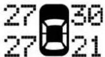
2345 mi
055900259
"LOWTIREPRESSURE"Message
Should this occur, you should stop as soon as possible and inflate the tires with a low pressure condition (those in a different color in the instrument cluster graphic) to the vehicle's recommended cold placard pressure inflation value as shown in the "Inflate to XX" message. Once the system receives the updated tire pressures, the system will automatically update, the graphic display in the instrument cluster will return to it's original color, and the "Tire Pressure Monitoring Telltale Light" will turn off. The vehicle may need to be driven for up to 20 minutes above 15 mph (24 km/h) in order for the TPMS to receive this information.

182 SAFETY
ServiceTPMSWarning
If a system fault is detected, the "Tire Pressure Monitoring Telltale Light" will flash on and off for 75 seconds and then remain on solid. The system fault will also sound a chime. In addition, the instrument cluster will display a "SERVICE TPM SYSTEM" message for a minimum of five seconds and then display dashes (- -) in place of the pressure value to indicate which sensor is not being received.
EXAMPLE ONLY

text_image
Tire PSI 30 33 30 --055900260
TirePressureMonitorDisplay
If the ignition switch is cycled, this sequence will repeat, providing the system fault still exists. If the system fault no longer exists, the "Tire Pressure Monitoring Telltale Light" will no longer flash, and the "SERVICE TPM SYSTEM" message will no longer display, and a pressure value will display in place of the dashes. A system fault can occur due to any of the following:
- Signal interference due to electronic devices or driving next to facilities emitting the same radio frequencies as the TPM sensors.
- Installing aftermarket window tinting that contains materials that may block radio wave signals.
- Accumulation of snow or ice around the wheels or wheel housings.
• Using tire chains on the vehicle. - Using wheels/tires not equipped with TPM sensors.
A system fault may occur due to an incorrect TPM sensor location condition. When a system fault occurs due to an incorrect TPM sensor location, the "Tire Pressure Monitoring Telltale Light" will flash on and off for 75 seconds and then remain on solid. The system fault will also sound a chime. In addition, the instrument cluster will display a "Tire Pressure Temporarily Unavailable" message in place of the tire pressure display screen. If the ignition switch is cycled, this sequence will repeat, providing the system fault still exists. If the system fault no longer exists, the "Tire Pressure Monitoring Telltale Light" will no longer
flash and the tire pressure display screen will be displayed showing the tire pressure values for the correct locations.
VehiclesWithNonMatchingFullSizeSpareOrCompact Spare
- The non matching full size spare or compact spare tire does not have a TPM sensor. Therefore, the TPMS will not monitor the pressure in the non matching full size spare or compact spare tire.
- If you install the non matching full size spare or compact spare tire in place of a road tire that has a pressure below the low-pressure warning limit, upon the next ignition switch cycle, the TPM Telltale Light and a "LOW TIRE" message will remain ON and a chime will sound. In addition, the graphic in the instrument cluster will still display a pressure value in a different color and an "Inflate to XX" message.
-
After driving the vehicle for up to 20 minutes above 15 mph (24 km/h), the TPM Telltale Light will flash on and off for 75 seconds and then remain on solid. In addition, the instrument cluster will display a "SERVICE TPM SYSTEM" message for a minimum of five seconds and then display dashes (- -) in place of the pressure value.
-
For each subsequent ignition switch cycle, a chime will sound, the TPM Telltale Light will flash on and off for 75 seconds and then remain on solid, and the instrument cluster will display a "SERVICE TPM SYSTEM" message for a minimum of five seconds and then display dashes (- -) in place of the pressure value.
- Once you repair or replace the original road tire and reinstall it on the vehicle in place of the non matching full size spare or compact spare, the TPMS will update automatically. In addition, the TPM Telltale Light will turn OFF and the graphic in the instrument cluster will display a new pressure value instead of dashes (- -), as long as no tire pressure is below the low-pressure warning limit in any of the four active road tires. The vehicle may need to be driven for up to 20 minutes above 15mph (24km / h) in order for the TPMS to receive this information.
TirePressureInformationSystem(TPIS)Chassis Cab—IfEquipped
Your vehicle may be equipped with a Tire Pressure Information System (TPIS).
The Tire Pressure Information System (TPIS) uses wireless technology with wheel rim mounted electronic sensors to

184 SAFETY
transmit tire pressure levels. Sensors mounted to each wheel as part of the valve stem transmit tire pressure readings to the receiver module.
NOTE: It is particularly important for you to check the tire pressure in all of the tires on your vehicle monthly and to maintain the proper pressure.
The TPIS consists of the following components:
- Receiver module
- Four TPM sensors (Single Rear Wheel [SRW] applications)
- Six TPM sensors (Dual Rear Wheel [DRW] applications)
- Pressure display in the instrument cluster display.
The TPIS system will display all four (Single Rear Wheel [SRW] applications) or six (Dual Rear Wheel [DRW] applications) tire pressure values in the instrument cluster display.
If a system fault is detected, the instrument cluster will display a "SERVICE TPM SYSTEM" message for a minimum of five seconds and then display dashes (- -) in place of the pressure value to indicate which sensor is not being received.
If the ignition switch is cycled, this sequence will repeat, providing the system fault still exists. If the system fault no longer exists, the "SERVICE TPM SYSTEM" message will no longer be displayed, and a pressure value will display in place of the dashes. A system fault can occur due to any of the following:
- Signal interference due to electronic devices or driving next to facilities emitting the same radio frequencies as the TPM sensors.
- Installing aftermarket window tinting that contains materials that may block radio wave signals.
- Accumulation of snow or ice around the wheels or wheel housings.
• Using tire chains on the vehicle. - Using wheels/tires not equipped with TPM sensors.
GeneralInformation
This device complies with Part 15 of the FCC rules and RSS 210 of Industry Canada. Operation is subject to the following conditions:
- This device may not cause harmful interference.

- This device must accept any interference received, including interference that may cause undesired operation.
NOTE: Changes or modifications not expressly approved by the party responsible for compliance could void the user's authority to operate the equipment.
OCCUPANT RESTRAINT SYSTEMS
Some of the most important safety features in your vehicle are the restraint systems:
Occupant Restraint Systems Features
- Seat Belt Systems
• Supplemental Restraint Systems (SRS) Air Bags - Child Restraints
Some of the safety features described in this section may be standard equipment on some models, or may be optional equipment on others. If you are not sure, ask an authorized dealer.
Important Safety Precautions
Please pay close attention to the information in this section. It tells you how to use your restraint system properly, to keep you and your passengers as safe as possible. Here are some simple steps you can take to minimize the risk of harm from a deploying air bag:
- Children 12 years old and under should always ride buckled up in the rear seat of a vehicle with a rear seat.
- If a child from 2 to 12 years old (not in a rear-facing child restraint) must ride in the front passenger seat, move the seat as far back as possible and use the proper child restraint (refer to "Child Restraints" in this section for further information).
- Children that are not big enough to wear the vehicle seat belt properly (refer to "Child Restraints" in this section for further information) should be secured in the rear seat of a vehicle with a rear seat in child restraints or belt-positioning booster seats. Older children who do not use child restraints or belt-positioning booster seats should ride properly buckled up in the rear seat of a vehicle with a rear seat.
- Never allow children to slide the shoulder belt behind them or under their arm.
- You should read the instructions provided with your child restraint to make sure that you are using it properly.

- All occupants should always wear their lap and shoulder belts properly.
- The driver and front passenger seats should be moved back as far as practical to allow the front air bags room to inflate.
- Do not lean against the door or window. If your vehicle has side air bags, and deployment occurs, the side air bags will inflate forcefully into the space between occupants and the door and occupants could be injured.
- If the air bag system in this vehicle needs to be modified to accommodate a disabled person, refer to the "Customer Assistance" section for customer service contact information.
WARNING!
- Neverplacearear-facingchildrestraintinfrontofan airbag. Adeployingpassengerfrontairbagcan causedeathorseriousinjurytoachild12yearsor younger, includingachildinarear-facingchild restraint.
- Onlyusearear-facingchildrestraintintherearseat ofavehiclewitharearseat.
Seat Belt Systems
Buckle up even though you are an excellent driver, even on short trips. Someone on the road may be a poor driver and could cause a collision that includes you. This can happen far away from home or on your own street.
Research has shown that seat belts save lives, and they can reduce the seriousness of injuries in a collision. Some of the worst injuries happen when people are thrown from the vehicle. Seat belts reduce the possibility of ejection and the risk of injury caused by striking the inside of the vehicle. Everyone in a motor vehicle should be belted at all times.
EnhancedSeatBeltUseReminderSystem(BeltAlert)
DriverandPassengerBeltAlert(ifequipped)
3 BeltAlert is a feature intended to remind the driver and outboard front seat passenger (if equipped with outboard front passenger seat BeltAlert) to buckle their seat belts. The Belt Alert feature is active whenever the ignition switch is in the START or ON/RUN position.
InitialIndication
If the driver is unbuckled when the ignition switch is first in the START or ON/RUN position, a chime will signal for

a few seconds. If the driver or outboard front seat passenger (if equipped with outboard front passenger seat BeltAlert) is unbuckled when the ignition switch is first in the START or ON/RUN position the Seat Belt Reminder Light will turn on and remain on until both outboard front seat belts are buckled. The outboard front passenger seat BeltAlert is not active when an outboard front passenger seat is unoccupied.
BeltAlertWarningSequence
The BeltAlert warning sequence is activated when the vehicle is moving above a specified vehicle speed range and the driver or outboard front seat passenger is unbuckled (if equipped with outboard front passenger seat BeltAlert) (the outboard front passenger seat BeltAlert is not active when the outboard front passenger seat is unoccupied). The BeltAlert warning sequence starts by blinking the Seat Belt Reminder Light and sounding an intermittent chime. Once the BeltAlert warning sequence has completed, the Seat Belt Reminder Light will remain on until the seat belts are buckled. The BeltAlert warning sequence may repeat based on vehicle speed until the driver and occupied outboard front seat passenger seat belts are buckled. The driver should instruct all occupants to buckle their seat belts.
ChangeofStatus
If the driver or outboard front seat passenger (if equipped with outboard front passenger seat BeltAlert) unbuckles their seat belt while the vehicle is traveling, the BeltAlert warning sequence will begin until the seat belts are buckled again.
The outboard front passenger seat BeltAlert is not active when the outboard front passenger seat is unoccupied. BeltAlert may be triggered when an animal or other items are placed on the outboard front passenger seat or when the seat is folded flat (if equipped). It is recommended that pets be restrained in the rear seat (if equipped) in pet harnesses or pet carriers that are secured by seat belts, and cargo is properly stowed.
BeltAlert can be activated or deactivated by an authorized dealer. FCA US LLC does not recommend deactivating BeltAlert.
NOTE: If BeltAlert has been deactivated and the driver or outboard front seat passenger (if equipped with outboard front passenger seat BeltAlert) is unbuckled the Seat Belt Reminder Light will turn on and remain on until the driver and outboard front seat passenger seat belts are buckled.

188 SAFETY
Lap/ShoulderBelts
All seating positions except the Crew Cab front center seating position have combination lap/shoulder belts.
The seat belt webbing retractor will lock only during very sudden stops or collisions. This feature allows the shoulder part of the seat belt to move freely with you under normal conditions. However, in a collision the seat belt will lock and reduce your risk of striking the inside of the vehicle or being thrown out of the vehicle.
WARNING!
- Relyingontheairbagsalonecouldleadtomore severeinjuriesinacollision.Theairbagsworkwith yourseatbelttorestrainyouproperly.Insome collisions,theairbagswon'tdeployatall.Always wearyourseatbelteventhoughyouhaveairbags.
- Inacollision, you and your passengers can suffer much greater injuries if you are not properly buckled up. You can strike the interior of your vehicle or other passengers, or you can be thrown out of the vehicle. Always besure you and others in your vehicle are buckled up properly.
WARNING!(Continued)
- Itisdangeroustorideinacargoarea,insideor outsideofvehicle.Inacollision,peopleriding in theseareasaremorelikelytobeseriouslyinjuredor killed.
- Donotallowpeopletorideinanyareaofyour vehiclethatisnotequippedwithseatsandseatbelts.
- Besureeveryoneinyourvehicleisinaseatand usingaseatbeltproperly.Occupants,includingthe driver,shouldalwaysweartheirseatbeltswhether ornotanairbagisalsopvidedattheirseating positiontominimizetheriskofsevereinjuryor deathintheeventofacrash.
- Wearingyourseatbeltincorrectlycouldmakeyour injuriesinacollisionmuchworse.Youmightsuffer internalinjuries,oryoucouldevenslideoutofthe seatbelt.Followtheseinstructionstowearyourseat beltsafelyandtokeepyourpassengerssafe,too.
- Twopeopleshouldneverbebeltedintoasingleseat belt.Peoplebeltedtogethercancrashintooneanotherinacollision,hurtingoneanotherbadly.Never usealap/shoulderbeltoralapbeltformorethanone person,nomatterwhattheirsize.
WARNING!
- Alapbeltworntoohighcanincreasetheriskof injuryinacollision.Theseatbeltforceswon'tbeat thestronghipandpelvicbones,butacrossyour abdomen.Alwayswearthelappartofyourseatbelt aslowaspossibleandkeepitsnug.
- Atwistedseatbeltmaynotprotectyouproperly. In a collision, it could devencutintoyou. Besuretheseat beltisflatagainstyourbody, withouttwists. If you can't straightenaseatbeltinyourvehicle, takeitto anauthorizeddealerimmediately and haveitfixed.
- Aseatbeltthatisbuckledintothewrongbucklewill notprotectyouproperly. Thelapportioncouldride toohighonyourbody, possiblycausinginternal injuries. Alwaysbuckleyourseatbeltintothe bucklenearestyou.
- Aseatbeltthatistooloosewillnotprotectyou properly.Inasuddenstop,youcouldmovetoofar forward,increasingthepossibilityofinjury.Wear yourseatbeltsnugly.
- Aseatbeltthatiswornunderyourarmisdangerous. Yourbodycouldstriketheinsidesurfacesofthe vehicleinacollision,increasingheadandneck
WARNING!(Continued)
injury.Aseatbeltwornunderthearmcancause internalinjuries.Ribsaren'tasstrongassshoulder bones.Weartheseatbeltoveryourshouldersothat yourstrongestboneswilltaketheforceinacollision.
- Ashoulderbeltplacedbehindyouwillnotprotect youfrominjuryduringacollision.Youaremore likelytohityourheadinacollisionifyoudonot wearyourshoulderbelt.Thelapandshoulderbelt aremeanttbeusedtogether.
- Afrayedortornseatbeltcouldripapartinacollision andleaveyouwithnoprotection.Inspecttheseat beltsystemperiodically,checkingforcuts,frays,or looseparts.Damagedpartsmustbereplacedimmediately.Donotdisassembleormodifytheseatbelt system.Seatbeltassembliesmustbereplacedaftera collision.
Lap/ShoulderBeltOperatingInstructions
- Enter the vehicle and close the door. Sit back and adjust the seat.
190 SAFETY
- The seat belt latch plate is above the back of the front seat, and next to your arm in the rear seat (for vehicles equipped with a rear seat). Grasp the latch plate and pull out the seat belt. Slide the latch plate up the webbing as far as necessary to allow the seat belt to go around your lap.
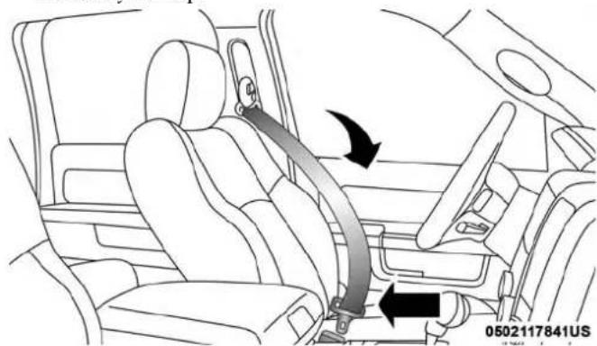
natural_image
Interior view of a car showing seatbelt and belt drive mechanism (no text or symbols)PullingOutTheLatchPlate
- When the seat belt is long enough to fit, insert the latch plate into the buckle until you hear a "click."

natural_image
Interior view of a car showing the seatbelt and dashboard (no text or symbols visible)InsertingLatchPlateIntoBuckle

- Position the lap belt so that it is snug and lies low across your hips, below your abdomen. To remove slack in the lap belt portion, pull up on the shoulder belt. To loosen the lap belt if it is too tight, tilt the latch plate and pull on the lap belt. A snug seat belt reduces the risk of sliding under the seat belt in a collision.

natural_image
Interior view of a car showing seatbelt and belt drive mechanism (no text or symbols)PositioningTheLapBelt
-
Position the shoulder belt across the shoulder and chest with minimal, if any slack so that it is comfortable and not resting on your neck. The retractor will withdraw any slack in the shoulder belt.
-
To release the seat belt, push the red button on the buckle. The seat belt will automatically retract to its stowed position. If necessary, slide the latch plate down the webbing to allow the seat belt to retract fully.
Lap/ShoulderBeltUntwistingProcedure
Use the following procedure to untwist a twisted lap/shoulder belt.
- Position the latch plate as close as possible to the anchor point.
- At about 6 to 12 inches (15 to 30 cm) above the latch plate, grasp and twist the seat belt webbing 180 degrees to create a fold that begins immediately above the latch plate.
- Slide the latch plate upward over the folded webbing. The folded webbing must enter the slot at the top of the latch plate.
- Continue to slide the latch plate up until it clears the folded webbing and the seat belt is no longer twisted.
192 SAFETY
AdjustableUpperShoulderBeltAnchorage
In the driver and front passenger seats, the top of the shoulder belt can be adjusted upward or downward to position the seat belt away from your neck. Push or squeeze the anchorage button to release the anchorage, and move it up or down to the position that serves you best.

text_image
AdjustableAnchorage 0502117864USAs a guide, if you are shorter than average, you will prefer the shoulder belt anchorage in a lower position, and if you are taller than average, you will prefer the shoulder belt anchorage in a higher position. After you release the anchorage button, try to move it up or down to make sure that it is locked in position.
NOTE: The adjustable upper shoulder belt anchorage is equipped with an Easy Up feature. This feature allows the shoulder belt anchorage to be adjusted in the upward position without pushing or squeezing the release button. To verify the shoulder belt anchorage is latched, pull downward on the shoulder belt anchorage until it is locked into position.
WARNING!
- Wearingyourseatbeltincorrectlycouldmakeyour injuriesinacollisionmuchworse.Youmightsuffer internalinjuries,oryoucouldevenslideoutofthe seatbelt.Followtheseinstructionstowearyourseat beltsafelyandtokeepyourpassengerssafe,too.
- Positiontheshoulderbeltacrosstheshoulderand chestwithminimal,ifanyslacksothatitiscomfortableandnotrestingonyourneck. Theretractorwill withdrawanyslackintheshoulderbelt.
- Misadjustmentoftheseatbeltcouldreducethe effectivenessofthesafetybeltinacrash.
SAFETY 193
FirstRowCenterSeatBeltOperatingInstructions (RegularCabOnly)
The first row center seat belt (Regular Cab only) features a seat belt with a mini-latch plate and buckle, which allows the seat belt to detach from the lower anchor when the seat is folded. The latch plate and regular latch plate can then be stored out of the way in the seat for added convenience to open up utilization of the storage areas behind the front seats when the seat is not occupied.
- Remove the mini-latch plate and regular latch plate from its stowed position on the seat.
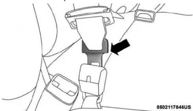
natural_image
Diagram of a car seatbelt buckle assembly with a black arrow indicating the component (no text or symbols present)ConnectMini-LatchToMini-Buckle

natural_image
Diagram of a car seatbelt mechanism with arrows indicating movement (no text or symbols)Mini-LatchAndMini-BuckleConnected
- Grasp the mini-latch plate and pull the seat belt over the seat.
- Route the shoulder belt to the inside of the right head restraint.
- When the seat belt is long enough to fit, insert the mini-latch plate into the mini-buckle until you hear a "click."
- Sit back in seat. Slide the regular latch plate up the webbing as far as necessary to allow the seat belt to go around your lap.

194 SAFETY
-
When the seat belt is long enough to fit, insert the latch plate into the buckle until you hear a "click."
-
Position the lap belt so that it is snug and lies low across your hips, below your abdomen. To remove slack in the lap belt portion, pull up on the shoulder belt. To loosen the lap belt if it is too tight, pull on the lap belt. A snug seat belt reduces the risk of sliding under the seat belt in a collision.
-
Position the shoulder belt on your chest so that it is comfortable and not resting on your neck. The retractor will withdraw any slack in the seat belt.
-
To release the seat belt, push the red button on the buckle.
-
To disengage the mini-latch plate from the mini-buckle for storage, insert the regular latch plate into the center red slot on the mini-buckle. The seat belt will automatically retract to its stowed position. If necessary, slide the latch plate down the webbing to allow the seat belt to retract fully. Insert the mini-latch plate and regular latch plate into its stowed position.

natural_image
Mechanical assembly diagram showing a belt buckle being inserted into a seat (no text or symbols present)DetachingMini-BuckleWithSeatBeltTongue
WARNING!
- Ifthemini-latchplateandmini-bucklearenotproperlyconnectedwhentheseatbeltisusedbyan occupant,theseatbeltwillnotbeabletoprovide properrestraintandwillincreasetheriskofinjuryin acollision.
- Whenreattachingthemini-latchplateandmini-buckle,ensuretheseatbeltwebbingisnottwisted. Ifthewebbingistwisted,followthepreceding
WARNING!(Continued)
proceduretodetachthemini-latchplateandmini-buckle,untwistthewebbing,andreattachthemini-latchplateandmini-buckle.
FirstRowCenterLapBeltOperatingInstructions—IfEquipped
The center seating position for the Crew Cab front seat has a lap belt only. To buckle the lap belt, slide the latch plate into the buckle until you hear a "click." To lengthen the lap belt, tilt the latch plate and pull.
To remove slack, pull the loose end of the webbing. Wear the lap belt snug against the hips. Sit back and upright in the seat, then adjust the seat belt as tightly as is comfortable.
SeatBeltExtender
If a seat belt is not long enough to fit properly, even when the webbing is fully extended and the adjustable upper shoulder belt anchorage (if equipped) is in its lowest position, an authorized dealer can provide you with a Seat Belt Extender. The Seat Belt Extender should be used only if the existing seat belt is not long enough. When the Seat
Belt Extender is not required for a different occupant, it must be removed.
WARNING!
- ONLYuseaSeatBeltExtenderifitisphysically requiredinordertoproperlyfittheoriginalseatbelt system.DONOTUSEtheSeatBeltExtenderif, whenworn,thedistancebetweenthefrontedge of theSeatBeltExtenderbuckleandthecenterofthe occupant'sbodyisLESSthan6inches.
- UsingaSeatBeltExtenderwhennotneededcan increasetheriskofseriousinjuryordeathina collision.OnlyusetheSeatBeltExtenderwhenthe lapbeltisnotlongenoughandonlyuseinthe recommendedseatingpositions.Removeandstore theSeatBeltExtenderwhennotneeded.
196 SAFETY
SeatBeltsAndPregnantWomen
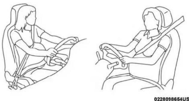
natural_image
Line drawings of a person seated in a car seat, showing two different positions (no text or symbols)PregnantWomenAndSeatBelts
Seat belts must be worn by all occupants including pregnant women: the risk of injury in the event of an accident is reduced for the mother and the unborn child if they are wearing a seat belt.
Position the lap belt snug and low below the abdomen and across the strong bones of the hips. Place the shoulder belt across the chest and away from the neck. Never place the shoulder belt behind the back or under the arm.
SeatBeltPretensioner—IfEquipped
The front seat belt system may be equipped with pretensioning devices that are designed to remove slack from the seat belt in the event of a collision. These devices may improve the performance of the seat belt by removing slack from the seat belt early in a collision. Pretensioners work for all size occupants, including those in child restraints.
NOTE: These devices are not a substitute for proper seat belt placement by the occupant. The seat belt still must be worn snugly and positioned properly.
The pretensioners are triggered by the Occupant Restraint Controller (ORC). Like the air bags, the pretensioners are single use items. A deployed pretensioner or a deployed air bag must be replaced immediately.
EnergyManagementFeature—IfEquipped
The front seat belt system may be equipped with an Energy Management feature that may help further reduce the risk of injury in the event of a collision. The seat belt system has a retractor assembly that is designed to release webbing in a controlled manner.

SwitchableAutomaticLockingRetractors(ALR)
The seat belts in the passenger seating positions may be equipped with a Switchable Automatic Locking Retractor (ALR) which is used to secure a child restraint system. For additional information, refer to "Installing Child Restraints Using The Vehicle Seat Belt" under the "Child Restraints" section of this manual. The figure below illustrates the locking feature for each seating position.
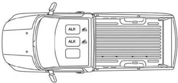
text_image
ALR ALR0502117873US
RegularCabAutomaticLockingRetractor(ALR)Locations
ALR = Switchable Automatic Locking Retractor
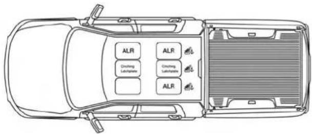
text_image
ALR ALR Cruching Lubrication Cruching Sublimation ALR0502117874US
CrewCabAutomaticLockingRetractor(ALR)Locations
ALR = Switchable Automatic Locking Retractor
If the passenger seating position is equipped with an ALR and is being used for normal usage, only pull the seat belt webbing out far enough to comfortably wrap around the occupant's mid-section so as to not activate the ALR. If the ALR is activated, you will hear a clicking sound as the seat belt retracts. Allow the webbing to retract completely in this case and then carefully pull out only the amount of webbing necessary to comfortably wrap around the occupant's mid-section. Slide the latch plate into the buckle until you hear a "click."

198 SAFETY
In Automatic Locking Mode, the shoulder belt is automatically pre-locked. The seat belt will still retract to remove any slack in the shoulder belt. Use the Automatic Locking Mode anytime a child restraint is installed in a seating position that has a seat belt with this feature. Children 12 years old and under should always be properly restrained in the rear seat of a vehicle with a rear seat.
WARNING!
- Neverplacearear-facingchildrestraintinfrontofan airbag. Adeployingpassengerfrontairbagcan causedethorseriousinjurytoachild12yearsor younger, includingachildinarear-facingchild restraint.
- Onlyusearear-facingchildrestraintintherearseat ofavehiclewitharearseat.
HowToEngageTheAutomaticLockingMode
- Buckle the combination lap and shoulder belt.
-
Grasp the shoulder portion and pull downward until the entire seat belt is extracted.
-
Allow the seat belt to retract. As the seat belt retracts, you will hear a clicking sound. This indicates the seat belt is now in the Automatic Locking Mode.
HowToDisengageTheAutomaticLockingMode
Unbuckle the combination lap/shoulder belt and allow it to retract completely to disengage the Automatic Locking Mode and activate the vehicle sensitive (emergency) locking mode.
WARNING!
- Theseatbeltassemblymustbereplacedifthe switchableAutomaticLockingRetractor(ALR)featureoranyotherseatbeltfunctionisnotworking properlywhencheckedaccordingtotheprocedures intheServiceManual.
- Failuretoreplacetheseatbeltassemblycouldincreaseetheriskofinjuryincollisions.
- DonotusetheAutomaticLockingModetorestrain occupantswhoarewearingtheseatbeltorchildren whoareusingboosterseats. Thelockedmodeisonly usedtoinstallrear-facingorforward-facingchild restraintsthathaveaharnessforrestrainingthe child.
Supplemental Restraint Systems (SRS)
Some of the safety features described in this section may be standard equipment on some models, or may be optional equipment on others. If you are not sure, ask an authorized dealer.
The air bag system must be ready to protect you in a collision. The Occupant Restraint Controller (ORC) monitors the internal circuits and interconnecting wiring associated with the electrical Air Bag System Components. Your vehicle may be equipped with the following Air Bag System Components:
AirBagSystemComponents
•Occupant Restraint Controller (ORC)
• Air Bag Warning Light
•Steering Wheel and Column
- Instrument Panel
- Knee Impact Bolsters
- Driver and Front Passenger Air Bags
- Seat Belt Buckle Switch
• Supplemental Side Air Bags — If Equipped
- Front and Side Impact Sensors — If Equipped
- Seat Belt Pretensioners — If Equipped
AirBagWarningLight

The ORC monitors the readiness of the electronic parts of the air bag system whenever the ignition switch is in the START or ON/RUN position. If the ignition switch is in the OFF position or in the ACC position, the air bag system is not on and the air bags will not inflate.
The ORC contains a backup power supply system that may deploy the air bag system even if the battery loses power or it becomes disconnected prior to deployment.
The ORC turns on the Air Bag Warning Light in the instrument panel for approximately four to eight seconds for a self-check when the ignition switch is first in the ON/RUN position. After the self-check, the Air Bag Warning Light will turn off. If the ORC detects a malfunction in any part of the system, it turns on the Air Bag Warning Light, either momentarily or continuously. A single chime will sound to alert you if the light comes on again after initial startup.

200 SAFETY
The ORC also includes diagnostics that will illuminate the instrument panel Air Bag Warning Light if a malfunction is detected that could affect the air bag system. The diagnostics also record the nature of the malfunction. While the air bag system is designed to be maintenance free, if any of the following occurs, have an authorized dealer service the air bag system immediately.
- The Air Bag Warning Light does not come on during the four to eight seconds when the ignition switch is first in the ON/RUN position.
- The Air Bag Warning Light remains on after the four to eight-second interval.
- The Air Bag Warning Light comes on intermittently or remains on while driving.
NOTE: If the speedometer, tachometer, or any engine related gauges are not working, the Occupant Restraint Controller (ORC) may also be disabled. In this condition the air bags may not be ready to inflate for your protection. Have an authorized dealer service the air bag system immediately.
WARNING!
IgnoringtheAirBagWarningLightinyourinstrument panelcouldmeanyouwon'thavetheairbagsystemto protectyouinacollision.Ifthelightdoesnotcomeon asabulbcheckwhentheignitionisfirstturnedon, staysonafteryoustartthevehicle,orifitcomesonas youdrive,haveanauthorizeddealerservicetheairbag systemimmediately.
FrontAirBags
This vehicle has front air bags and lap/shoulder belts for both the driver and front passenger. The front air bags are a supplement to the seat belt restraint systems. The driver front air bag is mounted in the center of the steering wheel. The passenger front air bag is mounted in the instrument panel, above the glove compartment. The words "SRS AIRBAG" or "AIRBAG" are embossed on the air bag covers.
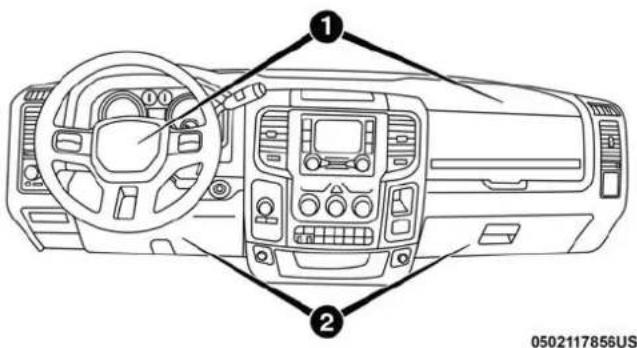
text_image
Diagram of a car dashboard with labeled parts, showing steering wheel, dashboard, and control panelsFrontAirBag/KneeBolsterLocations
1 — Driver And Passenger Front Air Bags
2 — Driver And Passenger Knee Impact Bolsters
WARNING!
- Beingtooclosetothesteeringwheelorinstrument panelduringfrontairbagdeploymentcouldcause seriousinjury,includingdeath.Airbagsneedroom toinflate.Sitback,comfortablyextendingyourarms toreachthesteeringwheelorinstrumentpanel.
WARNING!(Continued)
- Neverplacearear-facingchildrestraintinfrontofan airbag. A deployingpassengerfrontairbag can cause deathorserious injury toachild 12 years or younger, including achildinarear-facingchild restraint.
- Onlyusearear-facingchildrestraintintherearseat ofavehiclewitharearseat.
DriverAndPassengerFrontAirBagFeatures
The Advanced Front Air Bag system has multistage driver and front passenger air bags. This system provides output appropriate to the severity and type of collision as determined by the Occupant Restraint Controller (ORC), which may receive information from the front impact sensors (if equipped) or other system components.
The first stage inflator is triggered immediately during an impact that requires air bag deployment. A low energy output is used in less severe collisions. A higher energy output is used for more severe collisions.
This vehicle may be equipped with a driver and/or front passenger seat belt buckle switch that detects whether the driver or front passenger seat belt is buckled. The seat belt
buckle switch may adjust the inflation rate of the Advanced Front Air Bags.
WARNING!
- Noobjectsshouldbeplacedoverorneartheairbag ontheinstrumentpanelorsteeringwheelbecause anysuchobjectscouldcauseharmifthevehicleisin acollisionsevereenoughtocausetheairbagto inflate.
- Donotputanythingonoraroundtheairbagcovers orattempttoopenthemmanually.Youmaydamage theairbagsandyoucouldbeinjuredbecausetheair bagsmaynolongerbefunctional.Theprotective coversfortheairbagcushionsaredesignedtoopen onlywhentheairbagsareinflating.
- Relyingontheairbagsalonecouldleadtomore severeinjuriesinacollision.Theairbagsworkwith yourseatbelttorestrainyouproperly.Insome collisions,airbagswon'tdeployatall.Alwayswear yourseatbeltseventhoughyouhaveairbags.
FrontAirBagOperation
Front Air Bags are designed to provide additional protection by supplementing the seat belts. Front air bags are not expected to reduce the risk of injury in rear, s rollover collisions. The front air bags will not deploy in all frontal collisions, including some that may produce substantial vehicle damage — for example, some pole collisions, truck underrides, and angle offset collisions.
On the other hand, depending on the type and location of impact, front air bags may deploy in crashes with little vehicle front-end damage but that produce a severe initial deceleration.
Because air bag sensors measure vehicle deceleration over time, vehicle speed and damage by themselves are not good indicators of whether or not an air bag should have deployed.
Seat belts are necessary for your protection in all collisions, and also are needed to help keep you in position, away from an inflating air bag.
When the ORC detects a collision requiring the front air bags, it signals the inflator units. A large quantity of non-toxic gas is generated to inflate the front air bags.
The steering wheel hub trim cover and the upper passenger side of the instrument panel separate and fold out of the way as the air bags inflate to their full size. The front air
bags fully inflate in less time than it takes to blink your eyes. The front air bags then quickly deflate while helping to restrain the driver and front passenger.
KneeImpactBolsters
The Knee Impact Bolsters help protect the knees of the driver and front passenger, and position the front occupants for improved interaction with the front air bags.
WARNING!
- Donotdrill, cut, ortamper with the knee impact bolstersinanyway.
- Donotmountanyaccessoriestothekneeimpact bolsterssuchasalarmlights, stereos, citizenband radios, etc.
SupplementalSideAirBags
SupplementalSeat-MountedSideAirBags(SABs)—If Equipped
Your vehicle may be equipped with Supplemental Seat-Mounted Side Air Bags (SABs). If your vehicle is equipped with Supplemental Seat-Mounted Side Air Bags (SABs), please refer to the information below.
Supplemental Seat-Mounted Side Air Bags (SABs) are located in the outboard side of the front seats. The SABs are marked with "SRS AIRBAG" or "AIRBAG" on a label or on the seat trim on the outboard side of the seats.
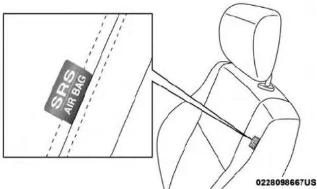
text_image
SRS AIR BAG 0228098667USSupplementalSeat-MountedSideAirBagLabel
The SABs (if equipped with SABs) may help to reduce the risk of occupant injury during certain side impacts, in addition to the injury reduction potential provided by the seat belts and body structure.
When the SAB deploys, it opens the seam on the outboard side of the seatback's trim cover. The inflating SAB deploys through the seat seam into the space between the occupant

204 SAFETY
and the door. The SAB moves at a very high speed and with such a high force that it could injure occupants if they are not seated properly, or if items are positioned in the area where the SAB inflates. Children are at an even greater risk of injury from a deploying air bag.
WARNING!
Donotuseaccessoryseatcoversorplaceobjects betweenyouandtheSideAirBags;theperformance couldbeadverselyaffectedand/orobjectscouldbe pushedintoyou,causingseriousinjury.
SupplementalSideAirBagInflatableCurtains(SABICs)—IfEquipped
Your vehicle may be equipped with Supplemental Side Air Bag Inflatable Curtains (SABICs). If your vehicle is equipped with Supplemental Side Air Bag Inflatable Curtains (SABICs), please refer to the information below.
Supplemental Side Air Bag Inflatable Curtains (SABICs) are located above the side windows. The trim covering the SABICs is labeled "SRS AIRBAG" or "AIRBAG."
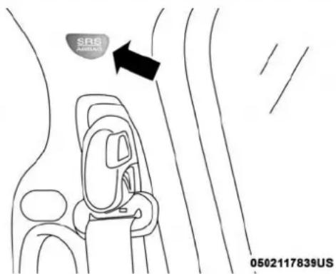
text_image
SRS ASPARS 0502117839USSupplementalSideAirBagInflatableCurtain(SABIC) LabelLocation
SABICs (if equipped with SABICs) may help reduce the risk of head and other injuries to front and rear seat outboard occupants in certain side impacts, in addition to the injury reduction potential provided by the seat belts and body structure.
The SABIC deploys downward, covering the side windows. An inflating SABIC pushes the outside edge of the headliner out of the way and covers the window. The SABICs inflate with enough force to injure occupants if they are not belted and seated properly, or if items are

positioned in the area where the SABICs inflate. Children are at an even greater risk of injury from a deploying air bag.
The SABICs (if equipped with SABICs) may help reduce the risk of partial or complete ejection of vehicle occupants through side windows in certain side impact events.
WARNING!
- Donotmountequipment,orstackluggageorother cargouphighenoughtoblockthedeploymentofthe SABICs. Thetrimcoveringabovethesidewindows wheretheSABICanditsdeploymentpatharelocatedshouldremainfreefromanyobstructions.
- InorderfortheSABICstoworkasintended,donot installanyaccessoryitemsinyourvehiclewhich couldaltertheroof.Donotaddanaftermarket sunrooftoyourvehicle.Donotaddroofracksthat requirepermanentattachments(boltsorscrews)for installationonthevehicleroof.Donotdrillintothe roofofthevehicleforanyreason.
SideImpacts
The Side Air Bags are designed to activate in certain side impacts. The Occupant Restraint Controller (ORC) determines whether the deployment of the Side Air Bags in a particular impact event is appropriate, based on the severity and type of collision. The side impact sensors aid the ORC in determining the appropriate response to impact events. The system is calibrated to deploy the Side Air Bags on the impact side of the vehicle during impacts that require Side Air Bag occupant protection. In side impacts, the Side Air Bags deploy independently; a left side impact deploys the left Side Air Bags only and a right-side impact deploys the right Side Air Bags only. Vehicle damage by itself is not a good indicator of whether or not Side Air Bags should have deployed.
The Side Air Bags will not deploy in all side collisions, including some collisions at certain angles, or some side collisions that do not impact the area of the passenger compartment. The Side Air Bags may deploy during angled or offset frontal collisions where the front air bags deploy.
Side Air Bags are a supplement to the seat belt restraint system. Side Air Bags deploy in less time than it takes to blink your eyes.
WARNING!
- Occupants, including children, who are up against the very closeto Side Air Bags can be seriously injured or killed. Occupants, including children, should never lean onorsleep against the door, sidewindows, or are a where the side air bags inflate, even if they are in an infant or child restraint.
- Seatbelts(and childrestraintswhereappropriate) are necessary for your protection in all collisions. They also help keep you in position, away from an inflating Side Air Bag. To get the best protection from the Side Air Bags, occupants must wear their seat belts properly and sit upright with their backs against these seats. Children must be properly restrained in child restraintor booster seat that is appropriate for the size of the child.
WARNING!
- SideAirBagsneedroomtoinflate.Donotlean againstthedoororwindow.Situprightinthecenter oftheseat.
- BeingtooclosetotheSideAirBagsduringdeploymentcouldcauseyoutobeseverelyinjuredorkilled.
- RelyingontheSideAirBagsalonecouldleadto moresevereinjuriesinacollision.TheSideAirBags workwithyourseatbelttorestrainyouproperly.In somecollisions,SideAirBagswon'tdeployatall. Alwayswearyourseatbelteventhoughyouhave SideAirBags.
NOTE: Air bag covers may not be obvious in the interior trim, but they will open during air bag deployment.
RolloverEvents(IfEquippedWithRolloverSensing)
Side Air Bags are designed to activate in certain rollover events. The Occupant Restraint Controller (ORC) determines whether the deployment of the Side Air Bags in a particular rollover event is appropriate, based on the severity and type of collision. Vehicle damage by itself is not a good indicator of whether or not Side Air Bags should have deployed.
The Side Air Bags will not deploy in all rollover events. The rollover sensing-system determines if a rollover event may be in progress and whether deployment is appropriate. A slower-developing event may deploy the seat belt pretensioners on both sides of the vehicle. A faster-developing event may deploy the seat belt pretensioners as well as the Side Air Bags on both sides of the vehicle. The rollover sensing-system may also deploy the seat belt pretensioners, with or without the Side Air Bags, on both sides of the vehicle if the vehicle experiences a near rollover event.
The SABICs may help reduce the risk of partial or complete ejection of vehicle occupants through side windows in certain rollover or side impact events.
AirBagSystemComponents
NOTE: The Occupant Restraint Controller (ORC) monitors the internal circuits and interconnecting wiring associated with electrical Air Bag System Components listed below:
•Occupant Restraint Controller (ORC)
• Air Bag Warning Light
•Steering Wheel and Column
- Instrument Panel
- Knee Impact Bolsters
- Driver and Front Passenger Air Bags
- Seat Belt Buckle Switch
• Supplemental Side Air Bags — If Equipped - Front and Side Impact Sensors — If Equipped
- Seat Belt Pretensioners — If Equipped
IfADeploymentOccurs
The front air bags are designed to deflate immediately after deployment.
NOTE: Front and/or side air bags will not deploy in all collisions. This does not mean something is wrong with the air bag system.
If you do have a collision which deploys the air bags, any or all of the following may occur:
- The air bag material may sometimes cause abrasions and/or skin reddening to the occupants as the air bags deploy and unfold. The abrasions are similar to friction rope burns or those you might get sliding along a carpet or gymnasium floor. They are not caused by contact with chemicals. They are not permanent and normally heal quickly. However, if you haven't healed significantly within a few days, or if you have any blistering, see your doctor immediately.

- As the air bags deflate, you may see some smoke-like particles. The particles are a normal by-product of the process that generates the non-toxic gas used for air bag inflation. These airborne particles may irritate the skin, eyes, nose, or throat. If you have skin or eye irritation, rinse the area with cool water. For nose or throat irritation, move to fresh air. If the irritation continues, see your doctor. If these particles settle on your clothing, follow the garment manufacturer's instructions for cleaning.
Do not drive your vehicle after the air bags have deployed. If you are involved in another collision, the air bags will not be in place to protect you.
WARNING!
Deployedairbagsandseatbeltpretensionerscannot protectyouinanothercollision.Havetheairbags,seat beltpretensioners,andtheseatbeltretractorassembliesreplacedbyanauthorizeddealerimmediately. Also,havetheOccupantRestraintControllerSystem servicedaswell.
NOTE:
- Air bag covers may not be obvious in the interior trim, but they will open during air bag deployment.
- After any collision, the vehicle should be taken to an authorized dealer immediately.
EnhancedAccidentResponseSystem
In the event of an impact, if the communication network remains intact, and the power remains intact, depending on the nature of the event, the ORC will determine whether to have the Enhanced Accident Response System perform the following functions:
- Cut off fuel to the engine (If Equipped)
- Cut off battery power to the electric motor (If Equipped)
- Flash hazard lights as long as the battery has power
- Turn on the interior lights, which remain on as long as the battery has power or for 15 minutes from the intervention of the Enhanced Accident Response System.
- Unlock the power door locks.
Your vehicle may also be designed to perform any of these other functions in response to the Enhanced Accident Response System:
- Turn off the Fuel Filter Heater, Turn off the HVAC Blower Motor, Close the HVAC Circulation Door
- Cut off battery power to the:
•Engine
• Electric Motor (if equipped)
• Electric power steering
- Brake booster
• Electric park brake
•Automatic transmission gear selector
• Horn
- Front wiper
•Headlamp washer pump
NOTE: After an accident, remember to cycle the ignition to the STOP (OFF/LOCK) position and remove the key from the ignition switch to avoid draining the battery. Carefully check the vehicle for fuel leaks in the engine compartment and on the ground near the engine compartment and fuel tank before resetting the system and starting the engine. If there are no fuel leaks or damage to the vehicle electrical devices (e.g. headlights) after an accident, reset the system by following the procedure described below.
EnhancedAccidentResponseSystemReset Procedure
In order to reset the Enhanced Accident Response System functions after an event, the ignition switch must be changed from ignition START or ON/RUN to ignition OFF. Carefully check the vehicle for fuel leaks in the engine compartment and on the ground near the engine compartment and fuel tank before resetting the system and starting the engine.
MaintainingYourAirBagSystem
WARNING!
- Modificationstoanypartoftheairbagsystemcould causeittofailwhenyouneedit.Youcouldbe injurediftheairbagsystemisnottheretoprotect you.Donotmodifythecomponentsorwiring,includingaddinganykindofbadgesorstickerstothe steeringwheelhubtrimcoverortheupperpassenger sideoftheinstrumentpanel.Donotmodifythefront bumper,vehiclebodystructure,oraddaftermarket sidestepsorrunningboards.
- Itisdangeroustotrytorepairanypartoftheairbag systemyourself.Besuretotellanyonewhoworkson yourvehiclethatithasanairbagsystem.
- Donotattempttomodifyanypartofyourairbag system. The airbag may inflate accidentally or may not function properly if modifications are made. Take your vehicle to an authorized dealer for any air bag systems service. If your seat, including your trim cover and cushion, need to be serviced in any way (including removal or loosening/tightening of seat attachment bolts), takethe vehicle to an authorized
WARNING!(Continued)
dealer.Onlymanufacturerapprovedseataccessories maybeused.Ifitisnecessarytomodifytheairbag systemforpersonswithdisabilities,contactanauthorizeddealer.
EventDataRecorder(EDR)
This vehicle is equipped with an event data recorder (EDR). The main purpose of an EDR is to record, in certain crash or near crash-like situations, such as an air bag deployment or hitting a road obstacle, data that will assist in understanding how a vehicle's systems performed. The EDR is designed to record data related to vehicle dynamics and safety systems for a short period of time, typically 30 seconds or less. The EDR in this vehicle is designed to record such data as:
- How various systems in your vehicle were operating;
- Whether or not the driver and passenger safety belts were buckled/fastened;
- How far (if at all) the driver was depressing the accelerator and/or brake pedal; and,
- How fast the vehicle was traveling.
These data can help provide a better understanding of the circumstances in which crashes and injuries occur.
NOTE:EDR data are recorded by your vehicle only if a non-trivial crash situation occurs; no data are recorded by the EDR under normal driving conditions and no personal data (e.g., name, gender, age, and crash location) are recorded. However, other parties, such as law enforcement, could combine the EDR data with the type of personally identifying data routinely acquired during a crash investigation.
To read data recorded by an EDR, special equipment is required, and access to the vehicle or the EDR is needed. In addition to the vehicle manufacturer, other parties, such as law enforcement, that have the special equipment, can read the information if they have access to the vehicle or the EDR.
Child Restraints
Everyone in your vehicle needs to be buckled up at all times, including babies and children. Every state in the United States, and every Canadian province, requires that small children ride in proper restraint systems. This is the law, and you can be prosecuted for ignoring it. Children 12 years or younger should ride properly buckled up in a rear seat, if available. According to crash statistics, children are safer when properly restrained in the rear seats rather than in the front.
WARNING!
Inacollision, an unrestrained child can become a projectile inside the vehicle. The forcerequired to hold even an infant on your lap could become so great that you could no hold the child, nomatter how strong you are. The child and others could be badly injured or killed. Any child riding in your vehicles should be a proper restraint for the child's size.
There are different sizes and types of restraints for children from newborn size to the child almost large enough for an adult safety belt. Always check the child seat Owner's Manual to make sure you have the correct seat for your child. Carefully read and follow all the instructions and warnings in the child restraint Owner's Manual and on all the labels attached to the child restraint.
Before buying any restraint system, make sure that it has a label certifying that it meets all applicable Safety Standards. You should also make sure that you can install it in the vehicle where you will use it.

212 SAFETY
NOTE:
- For additional information, refer to www.safercar.gov/parents/index.htm or call: 1-888-327-4236
- Canadian residents should refer to Transport Canada's website for additional information: http://www.tc.gc.ca/eng/motorvehiclesafety/safedrivers-childsafety-index-53.htm
SummaryOfRecommendationsForRestrainingChildrenInVehicles
| ChildSize,Height,WeightOrAge | RecommendedTypeOfChildRestraint | |
| Infants and Toddlers Children who are two years old or younger and who have not reached the height or weight limits of their child restraint | Either an Infant Carrier or a Convertible Child Restraint, facing rearward in the rear seat of the vehicle | |
| Small Children Children who are at least two years old or who have outgrown the height or weight limit of their rear-facing child restraint | Forward-Facing Child Restraint with a five-point Harness, facing forward in the rear seat of the vehicle | |
| Larger Children Children who have outgrown their forward-facing child restraint, but are too small to properly fit the vehicle's seat belt | Belt Positioning Booster Seat and the vehicle seat belt, seated in the rear seat of the vehicle | |
| Children Too Large for Child Restraints | Children 12 years old or younger, who have outgrown the height or weight limit of their booster seat | Vehicle Seat Belt, seated in the rear seat of the vehicle |

InfantAndChildRestraints
Safety experts recommend that children ride rear-facing in the vehicle until they are two years old or until they reach either the height or weight limit of their rear-facing child restraint. Two types of child restraints can be used rear-facing: infant carriers and convertible child seats.
The infant carrier is only used rear-facing in the vehicle. It is recommended for children from birth until they reach the weight or height limit of the infant carrier. Convertible child seats can be used either rear-facing or forward-facing in the vehicle. Convertible child seats often have a higher weight limit in the rear-facing direction than infant carriers do, so they can be used rear-facing by children who have outgrown their infant carrier but are still less than at least two years old. Children should remain rear-facing until they reach the highest weight or height allowed by their convertible child seat.
WARNING!
- Neverplacearear-facingchildrestraintinfrontofan airbag. A deployingpassengerfrontairbag can cause deathorserious injury toachild 12 years or younger, including achildinarear-facingchild restraint.
- Onlyusearear-facingchildrestraintintherearseat ofavehiclewitharearseat.
WARNING!
Donotinstallarear-facingcarseatusingarearsupport leginthisvehicle.Thefloorofthisvehicleisnot designedtomanagethecrashforcesofthistypeofcar seat.Inacrash,thesupportlegmaynotfunctionasit wasdesignedbythecarseatmanufacturer,andyour childmaybemoreseverelyinjuredasaresult.

natural_image
3D rendered illustration of a car seat with diagonal lines indicating crossed safety or clearance zones (no text or symbols)OlderChildrenAndChildRestraints
Children who are two years old or who have outgrown their rear-facing convertible child seat can ride forward-facing in the vehicle. Forward-facing child seats and convertible child seats used in the forward-facing direction are for children who are over two years old or who have outgrown the rear-facing weight or height limit of their rear-facing convertible child seat. Children should remain in a forward-facing child seat with a harness for as long as possible, up to the highest weight or height allowed by the child seat.
All children whose weight or height is above the forward-facing limit for the child seat should use a belt-positioning booster seat until the vehicle's seat belts fit properly. If the child cannot sit with knees bent over the vehicle's seat cushion while the child's back is against the seatback, they should use a belt-positioning booster seat. The child and belt-positioning booster seat are held in the vehicle by the seat belt.
WARNING!
- Improperinstallationcanleadtofailureofaninfant orchildrestraint.Itcouldcomelooseinacollision. Thechildcouldbebadlyinjuredorkilled.Follow thechildrestraintmanufacturer'sdirectionsexactly wheninstallinganinfantorchildrestraint.
- Afterachildrestraintisinstalledinthevehicle,do notmovethevehicleseatforwardorrearwardbecauseitcanloosenthechildrestraintattachments. Removethechildrestraintbeforeadjustingthevehicleseatposition.Whenthevehicleseathasbeen adjusted,reinstallthechildrestraint.
- When your child restraint is not in use, secure it in the vehicle with these seat belt or LATCH anchorages, or remove it from the vehicle. Don't leave it loose in the vehicle. In sudden stop or accident, it could strik the occupants or seat backs and causes serious personal injury.
ChildrenTooLargeForBoosterSeats
Children who are large enough to wear the shoulder belt comfortably, and whose legs are long enough to bend over the front of the seat when their back is against the seatback, should use the seat belt in a rear seat. Use this simple 5-step test to decide whether the child can use the vehicle's seat belt alone:
- Can the child sit all the way back against the back of the vehicle seat?
- Do the child's knees bend comfortably over the front of the vehicle seat – while the child is still sitting all the way back?
- Does the shoulder belt cross the child's shoulder between their neck and arm?
- Is the lap part of the belt as low as possible, touching the child's thighs and not the stomach?
- Can the child stay seated like this for the whole trip?
If the answer to any of these questions was "no," then the child still needs to use a booster seat in this vehicle. If the child is using the lap/shoulder belt, check seat belt fit periodically and make sure the seat belt buckle is latched. A child's squirming or slouching can move the belt out of position. If the shoulder belt contacts the face or neck, move the child closer to the center of the vehicle, or use a booster seat to position the seat belt on the child correctly.
WARNING!
Neverallowachildtoputtheshoulderbeltunderan armorbehindtheirback.Inacrash,theshoulderbelt willnotprotectachildproperly,whichmayresultin seriousinjuryordeath.Achildmustalwayswearboth thelapandshoulderportionsoftheseatbeltcorrectly.
RecommendationsForAttachingChildRestraints
| RestraintTypeCombined | UseAnyAttachmentMethodShownWithAn“X”Below | |||
| LATCH-Lower AnchorsOnly | SeatBeltOnlyLATCH-Lower Anchors+Top TetherAnchor | SeatBelt+Top TetherAnchor | ||
| Rear-Facing Child Restraint | Up to 65 lbs (29.5 kg) | X | X | |
| Rear-Facing Child Restraint | More than 65 lbs (29.5 kg) | X | ||
| Forward-Facing Child Restraint | Up to 65 lbs (29.5 kg) | X | ||
| Forward-Facing Child Restraint | More than 65 lbs (29.5 kg) | X | ||
LowerAnchorsAndTethersForCHILDREN(LATCH) RestraintSystem
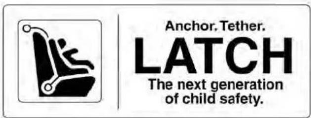
text_image
Anchor, Tether. LATCH The next generation of child safety.022668173
LATCHLabel
Your vehicle is equipped with the child restraint anchorage system called LATCH, which stands for Lower Anchors and Tethers for CHildren. The LATCH system has three vehicle anchor points for installing LATCH-equipped child seats. There are two lower anchorages located at the back of the seat cushion where it meets the seatback and one top tether anchorage located behind the seating position. These anchorages are used to install LATCH-equipped child seats without using the vehicle's seat belts. Some seating positions may have a top tether anchorage but no lower anchorages. In these seating positions, the seat belt must be
used with the top tether anchorage to install the child restraint. Please see the following table for more information.
LATCHPositionsForInstallingChildRestraintsIn ThisVehicle
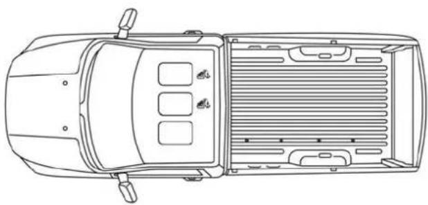
natural_image
Top-down line drawing of a car showing front and rear views with no text or symbols0502117857US
RegularCabLATCHPositions
Top Tether Anchorage Symbol

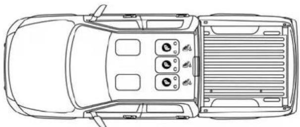
natural_image
Top-down line drawing of a car showing front, rear, and side views with no text or symbols0502117872US
CrewCab60/40SplitBenchLATCHPositions
Lower Anchorage Symbol (2 Anchorages Per Seating Position)
Top Tether Anchorage Symbol

natural_image
Top-down line drawing of a car showing front, rear, and side views with no text or symbols0502117862US
CrewCabFullBenchLATCHPositions
Lower Anchorage Symbol (2 Anchorages Per Seating Position)
Top Tether Anchorage Symbol
| FrequentlyAskedQuestionsAboutInstallingChildRestraintsWithLATCH | ||
| What is the weight limit (child's weight + weight of the child restraint) for using the LATCH anchorage system to attach the child restraint? | 65 lbs (29.5 kg) Use the LATCH anchorage system until the combined weight of the child and the child restraint is 65 lbs (29.5 kg). Use the seat belt and tether anchor instead of the LATCH system once the combined weight is more than 65 lbs (29.5 kg). | |

SAFETY 219
| FrequentlyAskedQuestionsAboutInstallingChildRestraintsWithLATCH | ||
| Can the LATCH anchorages and the seat belt be used together to attach a rear-facing or forward-facing child restraint? | No | Do not use the seat belt when you use the LATCH anchorage system to attach a rear-facing or forward-facing child restraint. Booster seats may be attached to the LATCH anchorages if allowed by the booster seat manufacturer. See your booster seat owner's manual for more information. |
| Can a child seat be installed in the center position using the inner LATCH lower anchorages? | No Full bench rear | seat only: Use the seat belt and tether anchor to install a child seat in the center seating position. |
| Can two child restraints be attached using a common lower LATCH anchorage? | No Never “share” | a LATCH anchorage with two or more child restraints. If the center position does not have dedicated LATCH lower anchorages, use the seat belt to install a child seat in the center position next to a child seat using the LATCH anchorages in an outboard position. |
220 SAFETY
| FrequentlyAskedQuestionsAboutInstallingChildRestraintsWithLATCH | ||
| Can the rear-facing child restraint touch the back of the front passenger seat? | Yes The child seat | may touch the back of the front passenger seat if the child restraint manufacturer also allows contact. See your child restraint owner's manual for more information. |
| Can the head restraints be removed? Yes | The head restraints can be removed in each seating position. | |
LocatingTheLATCHAnchorage—CrewCabOnly

The lower anchorages are round bars that are found at the rear of the seat cushion where it meets the seatback. They are just visible when you lean into the rear seat to install the child
restraint. You will easily feel them if you run your finger along the gap between the seatback and seat cushion.

natural_image
Line drawing of a car seatbelt with two black arrows indicating downward movement (no text or symbols)CrewCabRearOutboardSeatsDriverSide
SAFETY 221
LocatingTheUpperTetherAnchorage

Regular Cab models have tether strap anchorages behind the front center and right seats. Crew Cab models have tether strap anchorages located behind each of the rear seats.
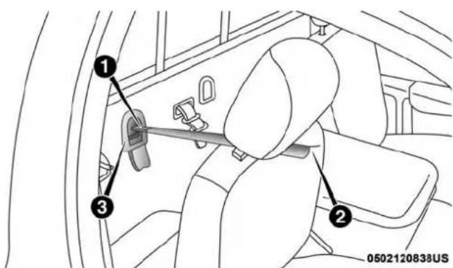
text_image
① ② ③ 0502120838USRegularCabTetherAnchorage(BehindCovers)
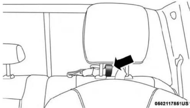
natural_image
Line drawing of a car seatbelt seat with a black arrow pointing to the seat (no text or symbols)CrewCabOutboardTetherAnchorage
1 — Tether Strap Hook
2 — Tether Strap To Child Restraint
3 — Tether Anchor

222 SAFETY
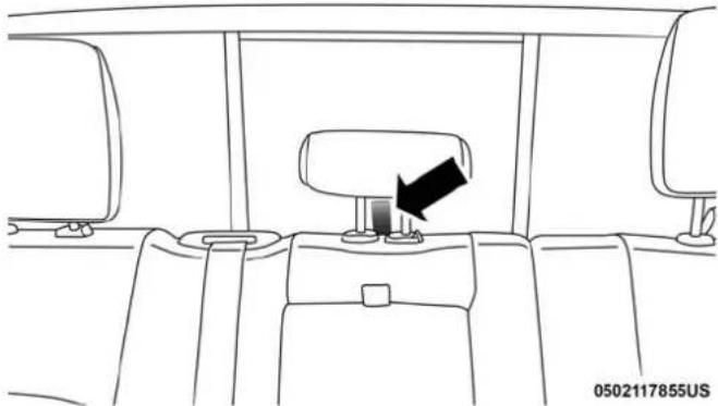
natural_image
Line drawing of a car interior showing seatbelt and dashboard (no text or symbols)CrewCabCenterTetherAnchorageWithHeadRestraint InRaisedPosition
LATCH-compatible child restraint systems will be equipped with a rigid bar or a flexible strap on each side. Each will have a hook or connector to attach to the lower anchorage and a way to tighten the connection to the anchorage. Forward-facing child restraints and some rear-facing child restraints will also be equipped with a tether strap. The tether strap will have a hook at the end to attach to the top tether anchorage and a way to tighten the strap after it is attached to the anchorage.
CenterSeatLATCH
RegularCabOrCrewCabFullBenchRearSeat:No LowerCenterLATCHAnchorageAvailable
WARNING!
- Donotinstallachildrestraintinthecenterposition usingtheLATCHsystem. ThispositionisnotapprovedforinstallingchildseatsusingtheLATCH attachments. Youmustusetheseatbeltandtether anchortoinstallachildseatinthecenterseating position.
- Neverusethesameloweranchoragetoattachmore thanonechildrestraint.
- Pleasereferto"ToInstallALATCH-Compatible ChildRestraint"fortypicalinstallationinstructions.
CrewCabSplitBenchRearSeat:CenterLATCHAnchorageAvailable
If a child restraint installed in the center position blocks the seat belt webbing or buckle for the outboard position, do not use that outboard position. If a child seat in the center position blocks the outboard LATCH anchors or seat belt, do not install a child seat in that outboard position.

WARNING!
Neverusethesameloweranchoragetoattachmore thanonechildrestraint.
Pleasereferto"ToInstallALATCH-CompatibleChild Restraint"fortypicalinstallationinstructions.
Always follow the direction of the child restraint manufacturer when installing your child restraint. Not all child restraints system will be installed as described here.
ToInstallALATCH-CompatibleChildRestraint
If the selected seating position has a Switchable Automatic Locking Retractor (ALR) seat belt, stow the seat belt, following the instructions below. See the section "Installing Child Restraints Using the Vehicle Seat Belt" to check what type of seat belt each seating position has.
-
Loosen the adjusters on the lower straps and on the tether strap of the child seat so that you can more easily attach the hooks or connectors to the vehicle anchorages.
-
Place the child seat between the lower anchorages for that seating position. For some second row seats, you may need to recline the seat and / or raise the head restraint to get a better fit. If the rear seat can be moved forward and rearward in the vehicle, you may wish to move it to its rear-most position to make room for the child seat. You may also move the front seat forward to allow more room for the child seat.
- Attach the lower hooks or connectors of the child restraint to the lower anchorages in the selected seating position.
- If the child restraint has a tether strap, connect it to the top tether anchorage. See the section "Installing Child Restraints Using the Top Tether Anchorage" for directions to attach a tether anchor.
- Tighten all of the straps as you push the child restraint rearward and downward into the seat. Remove slack in the straps according to the child restraint manufacturer's instructions.
- Test that the child restraint is installed tightly by pulling back and forth on the child seat at the belt path. It should not move more than 1 inch (25.4 mm) in any direction.
HowToStowAnUnusedSwitchable-ALR(ALR) SeatBelt:
When using the LATCH attaching system to install a child restraint, stow all ALR seat belts that are not being used by other occupants or being used to secure child restraints. An unused belt could injure a child if they play with it and accidentally lock the seat belt retractor. Before installing a child restraint using the LATCH system, buckle the seat belt behind the child restraint and out of the child's reach. If the buckled seat belt interferes with the child restraint installation, instead of buckling it behind the child restraint, route the seat belt through the child restraint belt path and then buckle it. Do not lock the seat belt. Remind all children in the vehicle that the seat belts are not toys and that they should not play with them.
WARNING!
- Improperinstallationofachildrestrainttothe LATCHanchoragescanleadtofailureofthere-straint.Thechildcouldbebadlyinjuredorkilled. Followthechildrestraintmanufacturer'sdirections exactlywheninstallinganinfantorchildrestraint.
WARNING!(Continued)
- Childrestraintanchoragesaredesignedtowithstand onlythoseloadsimposedbycorrectly-fittedchild restraints.Undernocircumstancesaretheytobe usedforadultseatbelts,harnesses,orforattaching otheritemsorequipmenttothevehicle.
InstallingChildRestraintsUsingTheVehicleSeat Belt
Child restraint systems are designed to be secured in vehicle seats by lap belts or the lap belt portion of a lap/shoulder belt.
WARNING!
- Improperinstallationorfailuretoproperlysecurea childrestraintcanleadtofailureoftherestraint.The childcouldbebadlyinjuredorkilled. - Followthechildrestraintmanufacturer'sdirections exactlywheninstallinganinfantorchildrestraint.
RegularCabOnly
The seat belts in the passenger seating positions are equipped with a Switchable Automatic Locking Retractor (ALR) that is designed to keep the lap portion of the seat belt tight around the child restraint so that it is not necessary to use a locking clip. The ALR retractor can be “switched” into a locked mode by pulling all of the webbing out of the retractor and then letting the webbing retract back into the retractor. If it is locked, the ALR will make a clicking noise while the webbing is pulled back into the retractor. Refer to the “Automatic Locking Mode” description in “Switchable Automatic Locking Retractors (ALR)” under “Occupant Restraint Systems” for additional information on ALR.
CrewCab:SplitBenchAndFullBench
The seat belts in the passenger seating positions are equipped with either a Switchable Automatic Locking Retractor (ALR) or a cinching latch plate or both. Both types of seat belts are designed to keep the lap portion of the seat belt tight around the child restraint so that it is not necessary to use a locking clip. The ALR retractor can be “switched” into a locked mode by pulling all of the webbing out of the retractor and then letting the webbing retract back into the retractor. If it is locked, the ALR will make a clicking noise while the webbing is pulled back into the retractor. Refer to the “Automatic Locking Mode” description in “Switchable Automatic Locking Retractors (ALR)” under “Occupant Restraint Systems” for additional information on ALR. The cinching latch plate is designed to hold the lap portion of the seat belt tight when webbing is pulled tight and straight through a child restraint’s belt path.

226 SAFETY
Please see the table below and the following sections for more information.
Lap/ShoulderBeltSystemsForInstallingChild RestraintsInThisVehicle

natural_image
Top-down line drawing of a car interior showing air vent, control panel, and exhaust grille (no text or symbols)0502117859US
RegularCabAutomaticLockingRetractor(ALR)Locations
ALR = Switchable Automatic Locking Retractor
Top Tether Anchorage Symbol
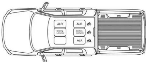
text_image
ALR AlR Cooling Latencyline Cooling Latencyline ALR0502117860US
CrewCabAutomaticLockingRetractor(ALR)Locations
Cinching Latchplate = Cinching Latchplate
ALR = Switchable Automatic Locking Retractor
Top Tether Anchorage Symbol
SAFETY 227
| FrequentlyAskedQuestionsAboutInstallingChildRestraintsWithSeatBelts | ||
| What is the weight limit (child's weight + weight of the child restraint) for using the Tether Anchor with the seat belt to attach a forward facing child restraint? | Weight limit of the Child Restraint Always use the tether anchor when using the seat belt to install a forward facing child restraint, up to the recommended weight limit of the child restraint. | |
| Can the rear-facing child restraint touch the back of the front passenger seat? | Yes Contact between the front passenger seat and the child restraint is allowed, if the child restraint manufacturer also allows contact. | |
| Can the head restraints be removed? Yes The head restraints can be removed | in each seating position. | |
| Can the buckle stalk be twisted to tighten the seat belt against the belt path of the child restraint? | Yes – Cinching Latch Plate No – ALR | In positions with cinching latch plates (CINCH), the buckle stalk may be twisted up to 3 full turns. Do not twist the buckle stalk in a seating position with an ALR retractor. |
InstallingAChildRestraintWithASwitchable AutomaticLockingRetractor(ALR):
Child restraint systems are designed to be secured in vehicle seats by lap belts or the lap belt portion of a lap/shoulder belt.
WARNING!
- Improperinstallationorfailuretoproperlysecurea childrestraintcanleadtofailureoftherestraint.The childcouldbebadlyinjuredorkilled.
- Follow the child restraint manufacturer's directions exactly when installing an infant or child restraint.
1. ForCrewCabModels
Place the child seat in the center of the seating position. For some second row seats, you may need to recline the seat and/or raise the head restraint to get a better fit. If the rear seat can be moved forward and rearward in the vehicle, you may wish to move it to its rear-most position to make room for the child seat. You may also move the front seat forward to allow more room for the child seat.
ForRegularCabModels
Place the child seat in the center of the seating position. Move the vehicle seat as far rearward as possible to keep the child as far from the passenger air bag as possible.
- Pull enough of the seat belt webbing from the retractor to pass it through the belt path of the child restraint. Do not twist the belt webbing in the belt path.
- Slide the latch plate into the buckle until you hear a "click."
- Pull on the webbing to make the lap portion tight against the child seat.
- To lock the seat belt, pull down on the shoulder part of the belt until you have pulled all the seat belt webbing out of the retractor. Then, allow the webbing to retract back into the retractor. As the webbing retracts, you will hear a clicking sound. This means the seat belt is now in the Automatic Locking mode.
-
Try to pull the webbing out of the retractor. If it is locked, you should not be able to pull out any webbing. If the retractor is not locked, repeat step 5.
-
Finally, pull up on any excess webbing to tighten the lap portion around the child restraint while you push the child restraint rearward and downward into the vehicle seat.
- If the child restraint has a top tether strap and the seating position has a top tether anchorage, connect the tether strap to the anchorage and tighten the tether strap. See the section "Installing Child Restraints Using the Top Tether Anchorage" for directions to attach a tether anchor.
- Test that the child restraint is installed tightly by pulling back and forth on the child seat at the belt path. It should not move more than 1 inch (25.4 mm) in any direction.
Any seat belt system will loosen with time, so check the belt occasionally, and pull it tight if necessary.
InstallingAChildRestraintWithACinchingLatch Plate(CINCH)—IfEquipped:
Child restraint systems are designed to be secured in vehicle seats by lap belts or the lap belt portion of a lap/shoulder belt.
WARNING!
- Improperinstallationorfailuretoproperlysecurea childrestraintcanleadtofailureoftherestraint.The childcouldbebadlyinjuredorkilled.
-
Follow the child restraint manufacturer's directions exactly when installing an infant or child restraint.
-
Place the child seat in the center of the seating position. For some second row seats, you may need to recline the seat and / or raise the head restraint to get a better fit. If the rear seat can be moved forward and rearward in the vehicle, you may wish to move it to its rear-most position to make room for the child seat. You may also move the front seat forward to allow more room for the child seat.
- Next, pull enough of the seat belt webbing from the retractor to pass it through the belt path of the child restraint. Do not twist the belt webbing in the belt path.
- Slide the latch plate into the buckle until you hear a "click."
- Finally, pull up on any excess webbing to tighten the lap portion around the child restraint while you push the child restraint rearward and downward into the vehicle

230 SAFETY
- If the child restraint has a top tether strap and the seating position has a top tether anchorage, connect the tether strap to the anchorage and tighten the tether strap. See the section "Installing Child Restraints Using the Top Tether Anchorage" for directions to attach a tether anchor.
- Test that the child restraint is installed tightly by pulling back and forth on the child seat at the belt path. It should not move more than 1 inch (25.4 mm) in any direction.
Any seat belt system will loosen with time, so check the belt occasionally, and pull it tight if necessary.
If the buckle or the cinching latch plate is too close to the belt path opening of the child restraint, you may have trouble tightening the seat belt. If this happens, disconnect the latch plate from the buckle and twist the short buckle-end belt up to three full turns to shorten it. Insert the latch plate into the buckle with the release button facing out, away from the child restraint. Repeat steps 4 to 6, above, to complete the installation of the child restraint.
If the belt still cannot be tightened after you shorten the buckle, disconnect the latch plate from the buckle, turn the buckle around one half turn, and insert the latch plate into the buckle again. If you still cannot make the child restraint installation tight, try a different seating position.
InstallingChildRestraintsUsingTheTopTether Anchorage
WARNING!
Donotattachatetherstrapforarear-facingcarseatto anylocationinfrontofthecarseat,includingtheseat frameoratetheranchorage.Onlyattachthetether strapofarear-facingcarseattothetetheranchorage thatisapprovedforthatseatingposition,located behindthetopofthevehicleseat.Seethesection "LowerAnchorsandTethersforCHildren(LATCH) RestraintSystem" forthelocationofapprovedtether anchoragesinyourvehicle.
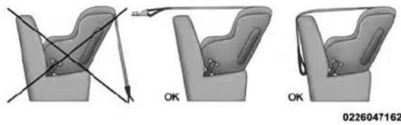
natural_image
Three-step illustration of a car seat assembly with diagonal lines indicating alignment, no text or symbols present.SAFETY 231
RegularCabTrucks:
In the regular cab truck, the top tether anchorages are located behind the center and right passenger seats. There is a plastic cover over each anchorage. To attach the tether strap of the child restraint:
- Place the child restraint on the seat and adjust the tether strap so that it will reach over the seat back, under the head restraint and to the tether anchor directly behind the seat.

text_image
1 3 2 0502117848US RegularCabTetherAnchorage1 — Tether Strap Hook
2 — Tether Strap To Child Restraint
3 — Tether Anchor
- Route the tether strap to provide the most direct path between the anchorage and the child seat. The tether strap should go between the head restraint posts underneath the head restraint. You may need to adjust the head restraint to the upward position to pass the tether strap underneath the head restraint and between its posts.
- Lift the cover (if so equipped), and attach the hook to the square opening in the sheet metal. Tighten the tether strap according to the child seat manufacturer's instructions.
WARNING!
Neverplacearear-facingchildrestraintinfrontofan airbag.AdeployingPassengerFrontAirBagcancause deathorseriousinjurytoachild12yearsoryounger, includingachildinarear-facingchildrestraint.
CrewCabTrucks:
The top tether anchorages in this vehicle are tether strap loops located between the rear glass and the back of the rear seat. There is a tether strap loop located behind each seating position. Follow the steps below to attach the tether strap of the child restraint.

232 SAFETY
RightOrLeftOutboardSeats:
- Raise the head restraint and reach between the rear seat and rear glass to access the tether strap loop.
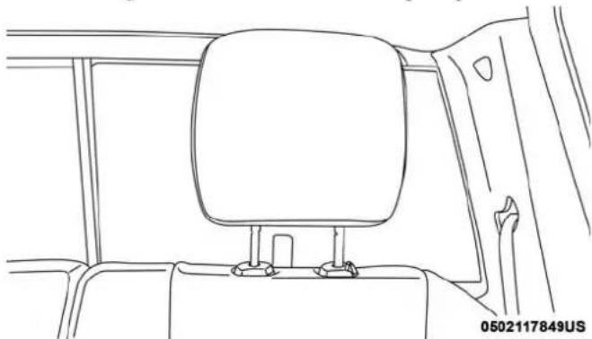
natural_image
Line drawing of a car backrest and seat assembly (no text or symbols)HeadRestraintInRaisedPosition
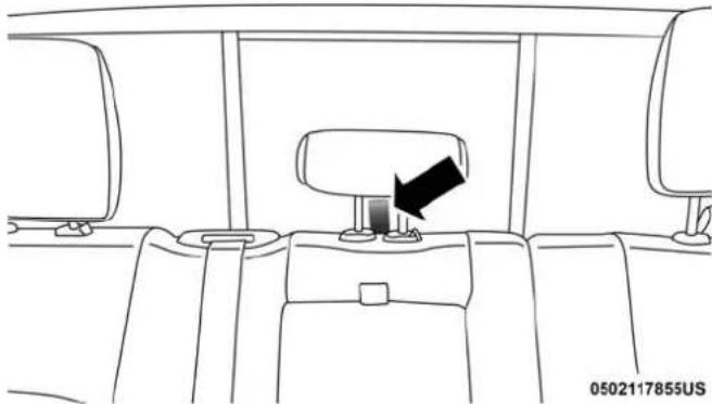
natural_image
Line drawing of a car interior showing seat, dashboard, and steering wheel (no text or symbols)TetherStrapLoopWithCenterHeadRestraintInRaised Position
- Place a child restraint on the seat and adjust the tether strap so that it will reach over the seat back, under the head restraint, through the tether strap loop behind the seat and over to the tether strap loop behind the center seat.
SAFETY 233
- Pass the tether strap hook under the head restraint behind the child seat, though the tether strap loop behind the seat and over to the center tether strap loop.

natural_image
Line drawing of a car seatbelt seat with a black arrow pointing to the seat (no text or symbols)- Attach the hook to the center tether strap loop (see diagram). Tighten the tether strap according to the child seat manufacturer's instructions.
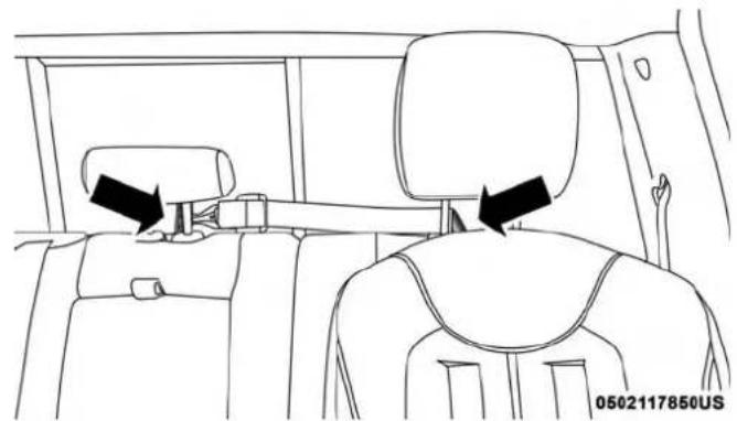
natural_image
Line drawing of a car backrest and seat assembly, showing two black arrows pointing to the seat (no text or symbols present)TetherStrapThroughOutboardTetherStrapLoopTetherStrapThroughOutboardTetherStrapLoopAnd
AttachedToCenterTetherStrapLoop
NOTE: If there are child seats in both of the outboard (left and right) seating positions, the tether strap hooks of both child seats should be connected to the center tether strap loop. This is the correct way to tether two outboard child seats.

234 SAFETY
CenterSeat:
- Raise the head restraint and reach between the rear seat and rear glass to access the tether strap loop.
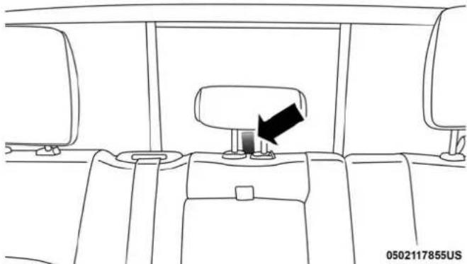
natural_image
Interior view of a car showing the seat, dashboard, and rear seats with a black arrow pointing to the wheel (no text or symbols)TetherStrapLoopWithHeadRestraintInRaisedPosition
- Place a child restraint on the seat and adjust the tether strap so that it will reach over the seat back, under the head restraint, through the tether strap loop behind the seat and over to the tether strap loop behind either the right or left outboard seat.
- Pass the tether strap hook under the head restraint behind the child seat, though the tether strap loop behind the seat and over to the right or left outboard tether strap loop.

natural_image
Line drawing of a car interior showing steering wheel, seatbelt, and dashboard (no text or symbols)TetherStrapThroughCenterTetherStrapLoop

SAFETY 235
- Attach the hook to the outboard tether strap loop (see diagram). Tighten the tether strap according to the child seat manufacturer's instructions.
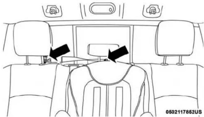
natural_image
Interior view of a car dashboard with seats and seatbelt (no text or symbols visible)TetherStrapThroughCenterTetherStrapLoopAnd AttachedToOutboardTetherStrapLoop
InstallingThreeChildRestraints:
-
Place a child restraint on each outboard rear seat. Route the tether straps following the directions for right and left seating positions, above.
-
Attach both hooks to the center tether strap loop, but do not tighten the straps yet.
-
Place a child restraint on the center rear seat. Route the tether strap following the directions for the center seating position, above.
- Attach the hook to the outboard tether strap loop.
- Tighten the tether straps according to the child seat manufacturer's instructions, tightening the right and left tether straps before the center tether strap.
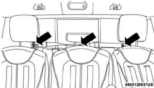
natural_image
Interior view of a car with seats and overhead air ducts, no visible text or symbolsOutboardAndCenterSeatingPositionsShown
WARNING!
- Anincorrectlyanchoredtetherstrapcouldleadto increasedheadmotionandpossibleinjurytothe child.Useonlytheanchoragepositiondirectlybehindthechildseattosecureachildrestrainttop tetherstrap.
- If your vehicle is equipped with a split rearseat, makes sure the ether strap does not slip into the opening between these at backs as you removes lack in the strap.
Transporting Pets
Air Bags deploying in the front seat could harm your pet. An unrestrained pet will be thrown about and possibly injured, or injure a passenger during panic braking or in a collision.
Pets should be restrained in the rear seat in pet harnesses or pet carriers that are secured by seat belts.
SAFETY TIPS
Transporting Passengers
NEVER TRANSPORT PASSENGERS IN THE CARGO AREA.
WARNING!
- Donotleavechildrenoranimalsinsideparked vehiclesinhotweather.Interiorheatbuild-upmay causeseriousinjuryordeath.
- Itisextremelydangeroustorideinacargoarea, insideoroutsideofvehicle.Inacollision,people ridingintheseareasaremorelikelytobeseriously injuredorkilled.
- Donotallowpeopletorideinanyareaofyour vehiclethatisnotequippedwithseatsandseatbelts.
- Besureeveryoneinyourvehicleisinaseatand usingaseatbeltproperly.
Exhaust Gas
WARNING!
Exhaustgasescaninjureorkill. They containcarbon monoxide(CO), which is colorless and odorless. Breathing it can make you unconscious and can eventually poison you. To avoid breathing(CO), follow the safety tips:
- Donotruntheengineinaclosedgarageorin confinedareasanylongerthanneededtomoveyour vehicleinoroutofthearea.
- If you are required to drivewith the trunk/lift gate/reard oorsopen, makes sure that all windows are closed and the climate control BLOWER switch isset athigh speed. DONOT usethere circulation mode.
- Ifitisnecessarytositinaparkedvehiclewiththe engineerunning,adjustyourheatingorcoolingcontrolstoforceoutsideairintothevehicle.Setthe blowerathighspeed.
The best protection against carbon monoxide entry into the vehicle body is a properly maintained engine exhaust system.
Whenever a change is noticed in the sound of the system, when exhaust fumes can be detected ins vehicle, or when the underside or rear of the vehicle is damaged, have a competent mechanic inspect the complete exhaust system and adjacent body areas for broken, damaged, deteriorated, or mispositioned parts. Open seams or loose connections could permit exhaust fumes to seep into the passenger compartment. In addition, inspect the exhaust system each time the vehicle is raised for lubrication or oil change. Replace as required.
Safety Checks You Should Make Inside The Vehicle
SeatBelts
Inspect the seat belt system periodically, checking for cuts, frays, and loose parts. Damaged parts must be replaced immediately. Do not disassemble or modify the system.
Front seat belt assemblies must be replaced after a collision. Rear seat belt assemblies must be replaced after a collision if they have been damaged (i.e., bent retractor, torn webbing, etc.). If there is any question regarding seat belt or retractor condition, replace the seat belt.
AirBagWarningLight
The Air Bag warning light will turn on for four to eight seconds as a bulb check when the ignition switch is first turned to ON/RUN. If the light is either not on during starting, stays on, or turns on while driving,

238 SAFETY
have the system inspected at your authorized dealer as soon as possible. After the bulb check, this light will illuminate with a single chime when a fault with the Air Bag System has been detected. It will stay on until the fault is removed. If the light comes on intermittently or remains on while driving, have your authorized dealer service the vehicle immediately.
Refer to "Occupant Restraint Systems" in "Safety" for further information.
Defroster
Check operation by selecting the defrost mode and place the blower control on high speed. You should be able to feel the air directed against the windshield. See your authorized dealer for service if your defroster is inoperable.
FloorMatSafetyInformation
Always use floor mats designed to fit your vehicle. Only use a floor mat that does not interfere with the operation of the accelerator, brake or clutch pedals. Only use a floor mat that is securely attached using the floor mat fasteners so it cannot slip out of position and interfere with the accelerator, brake or clutch pedals or impair safe operation of your vehicle in other ways.
WARNING!
Animproperlyattached,damaged,folded,orstacked floormat,ordamagedfloormatfastenersmaycause yourfloormattointerferewiththeaccelerator,brake, orclutchpedalsandcausealossofvehiclecontrol.To preventSERIOUSINJURYorDEATH:
- ALWAYSsecurelyattach yourfloormatusingthe floormatfasteners.DONOTinstallyourfloormat upsidedownorturnyourfloormatover.Lightlypull toconfirmmatissecuredusingthefloormatfastenersonaregularbasis.
- ALWAYSREMOVETHEEXISTINGFLOORMAT FROMTHEVEHICLE 🕒 beforeinstallinganyother floormat.NEVERinstallorstackanadditionalfloor matontopofanexistingfloormat.
(Continued)
WARNING!(Continued)
- ONLYinstallfloormatsdesignedtofityourvehicle. NEVERinstallafloormatthatcannotbeproperly attachedandsecuredtoyourvehicle.Ifafloormat needstobereplaced,onlyuseaFCAapprovedfloor matforthespecificmake,model,andyearofyour vehicle.
- ONLYYusethedriver'ssidefloormatonthedriver's sidefloorarea.Tocheckforinterference,withthe vehicleproperlyparkedwiththeengineoff,fully depresstheaccelerator,thebrake,andtheclutch pedal(ifpresent)tocheckforinterference.Ifyour floormatinterfereswiththeoperationofanypedal, orisnotsecuretothefloor,removethefloormat fromthevehicleandplacethefloormatinyour trunk.
- ONLYusethepassenger'ssidefloormatonthe passenger'ssidefloorarea.
- ALWAYSmakesureobjectscannotfallorslideinto thedriver'ssidefloorareawhenthevehicleis moving.Objectscanbecometrappedunderaccelerator,brake,orclutchpedalsandcouldcausealossof vehiclecontrol.
WARNING!(Continued)
- NEVERplaceanyobjectsunderthefloormat(e.g., towels, keys, etc.). Theseobjectscouldchangethe positionofthefloormatandmaycauseinterference withtheaccelerator,brake,orclutchpedals.
- If the vehicle carpet has been removed and re-installed, always properly attach carpet to the floor and check the floor at fasteners are secure to the vehicle carpet. Fully depresse each pedal to check for interference with the accelerator, brake, or clutch pedal sthenre - install the floor mats.
- It is recommended to only use mild soap and water to clean your floormats. After cleaning, always check your floormath has been properly installed and is secured by your vehicle using the floormat fasteners by lightly pulling that.
Periodic Safety Checks You Should Make Outside The Vehicle
Tires
Examine tires for excessive tread wear and uneven wear patterns. Check for stones, nails, glass, or other objects lodged in the tread or sidewall. Inspect the tread for cuts and cracks. Inspect sidewalls for cuts, cracks, and bulges.
240 SAFETY
Check the wheel bolts for tightness. Check the tires (including spare) for proper cold inflation pressure.
Lights
Have someone observe the operation of brake lights and exterior lights while you work the controls. Check turn signal and high beam indicator lights on the instrument panel.
DoorLatches
Check for proper closing, latching, and locking.
FluidLeaks
Check area under the vehicle after overnight parking for fuel, coolant, oil, or other fluid leaks. Also, if gasoline fumes are detected or if fuel, or brake fluid leaks are suspected. The cause should be located and corrected immediately.

STARTING AND OPERATING
CONTENTS
■STARTING THE ENGINE — GASOLINE ENGINE....244
□Automatic Transmission....244
□Normal Starting . . . . . . . . . . . . . . . . . . . . . . . . . . . . . . . . . . . . . . . . . . . . . . 244
□Keyless Enter-N-Go — Ignition....246
□If Engine Fails To Start....247
☐Cold Weather Operation (Below -22^ F Or -30^ C) .....248
□After Starting. .248
■ENGINE BLOCK HEATER — IF EQUIPPED . . . .248
■ENGINE BREAK-IN RECOMMENDATIONS . . .248
□Manually Shifted Transfer Case — If Equipped . .261
□Electronically Shifted Transfer Case (Four-Position Switch) — If Equipped .....265
■ LIMITED-SLIP DIFFERENTIAL .....270
□ Stationary Mode .....271
□Mobile Mode....272
■POWER STEERING. . . . . . . . . . . . . . . . . . . . . . . . . . . . . . . . . . . . . . . . . . . . . . . . . . . . . 273
□ Hydraulic Power Steering .....273
SPEED CONTROL .274

242 STARTING AND OPERATING
□To Activate....275
□To Set A Desired Speed. . . . . . . . . . . . . . . . . . . . . . . . . . . . . . . . . . . . . . . . . . . . . . . . . 275
□To Vary The Speed Setting . . . . . . . . . . . . . . . . . . . . . . . . . . . . . . . . . . . . . . . . . . . . . . . . . . . . . . . 275
□To Accelerate For Passing....276
□To Resume Speed....277
□To Deactivate....277
■PARKSENSE REAR PARK ASSIST — IF EQUIPPED....277
□ParkSense Sensors....277
□ParkSense Warning Display. . . . . . . . . . . . . . . . . . . . . . . . . . . . . . . . . . . . . . . . . . . . . . . . . 278
□ParkSense Display....278
□Enabling And Disabling ParkSense....281
□Service The ParkSense Rear Park Assist System. .281
□Cleaning The ParkSense System. . . . . . . . . . . . . . . . . . . . . . . . . . . . . . . . . . . . . . . . . . . . . . . . . . . . . . . . . . . . . . . . . .
□ ParkSense System Usage Precautions .....282
■PARKSENSE FRONT AND REAR PARK ASSIST — IF EQUIPPED....284
□ ParkSense Sensors .....284
□ParkSense Warning Display. . . . . . . . . . . . . . . . . . . . . . . . . . . . . . . . . . . . . . . . . . . . . . . . . . 285
□ParkSense Display .....285
□Enabling And Disabling Front And/Or Rear ParkSense....287
□Service The ParkSense Park Assist System . . . . .288
□Cleaning The ParkSense System. . . . . . . . . . . . . . . . . . . . . . . . . . . . . . . . . . . . . . . . . . . . . . . . . . . . . . . . . . . . . 288
□ ParkSense System Usage Precautions .....289
■PARKVIEW REAR BACK UP CAMERA — IF EQUIPPED....290
■REFUELING THE VEHICLE — GAS .....293
□Loose Fuel Filler Cap Message .....294
□Materials Added To Fuel . . . . . . . . . . . . . . . . . . . . . . . . . . . . . . . . . . . . . . 294
■VEHICLE LOADING....294
□Gross Vehicle Weight Rating (GVWR) .....294
□Payload....295
□Gross Axle Weight Rating (GAWR) .....295
□Tire Size .295
□ Rim Size .....295
STARTING AND OPERATING 243
□Inflation Pressure....295
□Curb Weight....295
□Loading....295
■TRAILER TOWING....296
□Common Towing Definitions. . . . . . . . . . . . . . . . . . . . . . . . . . . . . 296
□Trailer Hitch Type and Maximum Trailer Weight . . . . . . . . . . . . . . . . . . . . . . . . . . . . . . . . . . . . . . . . . . . . . . . . . . . . . . . . . 300
□Trailer Towing Weights (Maximum Trailer Weight Ratings)....301
□Trailer And Tongue Weight....301
□Towing Requirements....302
□Towing Tips....309
■SNOWPLOW....310
□2500/3500 Models Only . . . . . . . . . . . . . . . . . . . . . . . . . . . . . . . . . . . . . . . . . . . . . . . . . . 310
■RECREATIONAL TOWING (BEHIND MOTORHOME, ETC.) . . . . . . . . . . . . . . . . . . . . . . . . . . . . . . . . . . . . . . . . . . . . . . . . . . . 313
□ Towing This Vehicle Behind Another Vehicle. . . .313
□Recreational Towing — Two-Wheel Drive Models .....314
□Recreational Towing — Four-Wheel Drive Models .....314
■DRIVING TIPS....318
□Driving On Slippery Surfaces....318
□Driving Through Water....318
STARTING THE ENGINE — GASOLINE ENGINE
Before starting your vehicle, adjust your seat, adjust both inside and outside mirrors, and fasten your seat belt.
The starter should not be operated for more than 10-second intervals. Waiting a few seconds between such intervals will protect the starter from overheating.
WARNING!
- Whenleavingthevehicle,alwaysmakesurethe keylessignitionnodeisinthe"OFF"mode,remove thekeyfobfromthevehicleandlockthevehicle.
- Neverleavechildrenaloneinavehicle,orwithaccess toanunlockedvehicle.Allowingchildrentobeina vehicleunattendedisdangerousforanumberof reasons.Achildorotherscouldbeseriouslyorfatally injured.Childrenshouldbewarnednottotouchthe parkingbrake,brakepedalorthegearselector.
- Donotleavethekeyfobinornearthevehicle,orina locationaccessibletochildren,anddonotleavethe ignitionofavehicleequippedwithKeylessEnter-N-Go intheACCorON/RUNmode.Achildcouldoperate powerwindows,othercontrols,ormovethevehicle.
WARNING!(Continued)
- Donotleavechildrenoranimalsinsideparked vehiclesinhotweather.Interiorheatbuild-upmay causeseriousinjuryordeath.
Automatic Transmission
Start the engine with the gear selector in the NEUTRAL or PARK. Apply the brake before shifting into any driving range.
NOTE: This vehicle is equipped with at transmission shift interlockings system. The brake pedal must be pressed to shift out of PARK.
TipStartFeature
Donotpress the accelerator. Cycle the ignition switch briefly to the START position and release it. The starter motor will continue to run and will automatically disengage when the engine is running.
Normal Starting
Normal starting of either a warm or cold engine is obtained without pumping or pressing the accelerator pedal. Cycle the ignition to the RUN position and release when the engine starts. If the engine fails to start within 10 seconds,
cycle the ignition to the OFF position, wait five seconds, then repeat the "Normal Starting" procedure.
ToTurnOnTheEngineUsingTheENGINE START/STOPButton
- Transmission must be in PARK or NEUTRAL.
- Press and hold the brake pedal while pushing the ENGINE START/STOP button once.
- The system takes over and attempts to start the vehicle. If the vehicle fails to start, the starter will disengage automatically after 10 seconds.
- If you wish to stop the cranking of the engine prior to the engine starting, push the button again.
NOTE: Normal starting of either a cold or a warm engine is obtained without pumping or pressing the accelerator pedal.
ToTurnOffTheEngineUsingENGINE START/STOPButton
-
Place the gear selector in PARK, then push and release the ENGINE START/STOP button.
-
The ignition switch will return to the OFF mode.
- If the gear selector is not in PARK (with vehicle stopped) and the ENGINE START/STOP button is pushed once, the transmission will automatically select PARK and the engine will turn off, however the ignition will remain in the ACC mode (NOT the OFF mode). Never leave a vehicle out of the PARK position, or it could roll.
- If the vehicle speed is above 5 mph (8 km/h), the ENGINE START/STOP button must be held for two seconds (or three short pushes in a row) to turn the engine off. The ignition will remain in the ACC mode (NOT the OFF mode) if the engine is turned off when the transmission is not in PARK.
NOTE: If the ignition switch is left in the ACC or RUN (engine not running) mode and the transmission is in PARK, the system will automatically time out after 30 minutes of inactivity and the ignition will switch to the OFF mode.
246 STARTING AND OPERATING
IdleShutdown—6.4LEngineOnly
This feature can be enabled so that the truck will automatically shutdown when the truck has been idling for a set period of time when the engine is at operating temperature. Idle time can be set in 5 minute increments between 5 and 60 minutes. See your local authorized dealer to enable this feature.
NOTE: The idle shut down timer is disabled while the PTO is active.
ENGINESTART/STOPButtonFunctions—With Driver'sFootOFFTheBrakePedal(InPARKOr NEUTRALPosition)
The ENGINE START/STOP button operates similar to an ignition switch. It has three positions, OFF, ACC, RUN. To change the ignition switch positions without starting the vehicle and use the accessories follow these steps:
- Starting with the ignition in the OFF position:
- Push the ENGINE START/STOP button once to change the ignition to the ACC position.
- Push the ENGINE START/STOP button a second time to change the ignition to the RUN position.
- Push the ENGINE START/STOP button a third time to return the ignition to the OFF position.
Keyless Enter-N-Go — Ignition
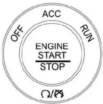
flowchart
graph TD
    A["ENGINE START STOP"] --> B["ACC"]
    B --> C["RUN"]
    C --> D["STOP"]
    D --> E["OFF"]
0101113902US
KeylessPushButtonIgnition
This feature allows the driver to operate the ignition switch with the push of a button, as long as the Remote Start/Keyless Enter-N-Go key fob is in the passenger compartment.

If Engine Fails To Start
If the engine fails to start after you have followed the "Normal Starting" procedure, it may be flooded. Push the accelerator pedal all the way to the floor and hold it there while the engine is cranking. This should clear any excess fuel in case the engine is flooded.
The starter motor will engage automatically, run for 10 seconds, and then disengage. Once this occurs, release the accelerator pedal and the brake pedal, wait 10 to 15 seconds, then repeat the "Normal Starting" procedure.
WARNING!
- Neverpourfuelorotherflammableliquidintothe throttlebodyairinletopeninginanattempttostart thevehicle. Thiscouldresultinflashfirecausing seriouspersonalinjury.
- Donotattempttopushortowyourvehicletogetit started. Vehiclesequippedwithanautomatictransmissioncannotbestedthisway.Unburnedfuel couldenterthecatalyticconverterandoncethe enginehasstarted,igniteanddamagetheconverter andvehicle.
WARNING!(Continued)
- If the vehicle has ad discharged battery, boostercables maybe used to obtain a start from a booster battery or the battery in another vehicle. This type of start can be dangerous if done improperly. Referto "Jump Starting Procedure" in "In Case Of Emergency" for further information.
CAUTION!
Topreventdamagetothestarter, donotcrank the engineformorethan10secondsatatime. Wait10to15 secondsbeforetryingagain.
If the engine has been flooded, it may start to run, but not have enough power to continue running when the ignition button/key is released. If this occurs, continue cranking with the accelerator pedal pushed all the way to the floor. Release the accelerator pedal and the ignition button/key once the engine is running smoothly.
If the engine shows no sign of starting after a 10 second period of engine cranking with the accelerator pedal held to the floor, wait 10 to 15 seconds, then repeat the "Normal
Starting" procedure.
248 STARTING AND OPERATING
Cold Weather Operation (Below -22°F Or -30°C)
To ensure reliable starting at these temperatures, use of an externally powered electric engine block heater (available from your authorized dealer) is recommended.
After Starting
The idle speed is controlled automatically, and it will decrease as the engine warms up.
ENGINE BLOCK HEATER — IF EQUIPPED
The engine block heater warms the engine, and permits quicker starts in cold weather. Connect the cord to a standard 110-115 Volt AC electrical outlet with a grounded, three-wire extension cord.
GasolineEngineOnly
The engine block heater cord is routed through the grille by the right front tow hook.
It includes a removable cap that is secured by a tethered strap. It also has a c-clip that is used for storage when not in use for the Winter months. During Winter months, remove the heater cord wiring assembly from itself on the c-clip.
The engine block heater must be plugged in at least one hour to have an adequate warming effect on the engine.
WARNING!
Remembertodisconnecttheengineblockheatercord beforedriving. Damagetothe110-115Voltelectrical cordcouldcauseelectrocution.
ENGINE BREAK-IN RECOMMENDATIONS
A long break-in period is not required for the engine and drivetrain (transmission and axle) in your vehicle.
Drive moderately during the first 300 miles (500 km). After the initial 60 miles (100 km), speeds up to 50 or 55 mph (80 or 90 km/h) are desirable.
While cruising, brief full-throttle acceleration within the limits of local traffic laws contributes to a good break-in. Wide-open throttle acceleration in low gear can be detrimental and should be avoided.
The engine oil installed in the engine at the factory is a high-quality energy conserving type lubricant. Oil changes should be consistent with anticipated climate conditions

under which vehicle operations will occur. For the recommended viscosity and quality grades, refer to "Fluids And Lubricants" in "Technical Specifications".
CAUTION!
NeveruseNon-DetergentOilorStraightMineralOil intheengineordamagemayresult.
NOTE:A new engine may consume some oil during its first few thousand miles (kilometers) of operation. This should be considered a normal part of the break-in and not interpreted as a problem. Please check your oil level with the engine oil indicator often during the break in period. Add oil as required.
PARKING BRAKE
Before leaving the vehicle, make sure that the parking brake is fully applied. Also, be certain to leave the transmission in PARK.
The foot operated parking brake is located below the lower left corner of the instrument panel. To apply the park brake, firmly push the park brake pedal fully. To release the parking brake, pull the parking brake release handle.
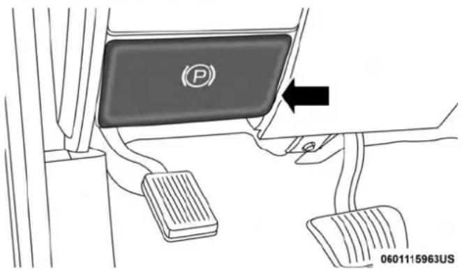
text_image
P 0601115963USParkingBrakeRelease
When the parking brake is applied with the ignition switch ON, the "Brake Warning Light" in the instrument cluster will illuminate.
NOTE:
- When the parking brake is applied and the transmission is placed in gear, the "Brake Warning Light" will flash. If vehicle speed is detected, a chime will sound to alert the driver. Fully release the parking brake before attempting to move the vehicle.
- This light only shows that the parking brake is applied. It does not show the degree of brake application.

250 STARTING AND OPERATING
When parking on a hill, it is important to turn the front wheels toward the curb on a downhill grade and away from the curb on an uphill grade. Apply the parking brake before placing the gear selector in PARK, otherwise the load on the transmission locking mechanism may make it difficult to move the gear selector out of PARK. The parking brake should always be applied whenever the driver is not in the vehicle.
WARNING!
- NeverusethePARKpositionasasubstituteforthe parkingbrake.Alwaysapplytheparkingbrakefully whenparkedtoguardagainstvehiclemovementand possibleinjuryordamage.
- Neverleavechildrenaloneinavehicle,orwithaccess toan unlocked vehicle.Leaving unattended children inavehicle is dangerous for an number of reasons. A child or others could be seriously or fatally injured.
- Donotleavethekeyfobinornearthevehicle,orinalocationaccessibletochildren,anddonotleavea vehicleequippedwithKeylessEnter-N-Gointhe ACCorON/RUNmode.Achildcouldoperatepower windows,othercontrols,ormovethevehicle.
WARNING!(Continued)
- Besuretheparkingbrakeisfullydisengagedbefore driving;failuretodosocanleadtobrakefailureand acollision.
- Alwaysfullyapplytheparkingbrakewhenleaving yourvehicleoritmayrollandcausedamageor injury. Also, becertaintoleavethetransmissionin PARK. Failuretodosomaycausethevehicletoroll andcausedamageorinjury.
CAUTION!
If the Brake System Warning Lightremainson with the parkingbrakereleased, abrakesystemmalfunction is indicated. Havethebrakesystemserviced by an authorized dealer immediately.
AUTOMATIC TRANSMISSION
WARNING!
- It is dangerous to shift out of PARK or NEUTRAL if the enginespeed is higher than needles speed. If your foot is not firmly pressing the brake pedal, the vehicle could accelerate quickly forward or in reverse. You could lose control of the vehicle and hits someone or something. Only shift to gear when the engine is idling normally and your foot is firmly pressing the brake pedal.
- Unintendedmovementofvehiclecouldinjure thoseinornearthevehicle.Aswithallvehicles,you shouldneverexitavehiclewhiletheengineis running.Beforeexitingavehicle,alwayscometoa completestop,thenapplytheparkingbrake,shift thetransmissionintoPARK,turntheengineOFF, andremovethekeyfob.Whentheignitionisinthe LOCK/OFF(keyremoval)position,(or,withKeyless Enter-N-Go,whentheignitionisintheOFFmode) thetransmissionislockedinPARK,securingthe vehicleagainstunwantedmovement.
- Whenleavingthevehicle,alwaysmakesurethe ignitionisintheOFFmode,removethekeyfobfrom thevehicle,andlockthevehicle.
WARNING!(Continued)
- NeverusethePARKpositionasasubstituteforthe parkingbrake.Alwaysapplytheparkingbrakefully whenexitingthevehicletoguardagainstvehicle movementandpossibleinjuryordamage.
- Yourvehiclecouldmoveandinjureyouandothersif itisnotinPARK.Checkbytryingtomovethegear selectoroutofPARKwiththebrakepedalreleased. MakesurethetransmissionisinPARKbeforeexitingthevehicle.
- Neverleavechildrenaloneinavehicle,orwith accesstoan unlocked vehicle. Allowingchildrento beinavehicleunattendedisdangerousforanumber ofreasons.Achildorotherscouldbeseriouslyor fatallyinjured.Childrenshouldbewarnednotto touchtheparkingbrake,brakepedalorthetransmissiongearselector.
- Donotleavethekeyfobinornearthevehicle(orinalocationaccessibletochildren),anddonotleave theignition(inavehicleequippedwithKeyless Enter-N-Go)intheACCorON/RUNmode.Achild couldoperatepowerwindows,othercontrols,or movethevehicle.
CAUTION!
Damagetothetransmissionmayoccurifthefollowing precautionsarenotobserved:
- ShiftintooroutofPARKorREVERSEonlyafterthe vehiclehascometoacompletestop.
- DonotshiftbetweenPARK, REVERSE, NEUTRAL, orDRIVEwhentheengineisaboveidlespeed.
- Beforeshiftingintoanygear,makesureyourfootis firmlypressingthebrakepedal.
NOTE: You must press and hold the brake pedal while shifting out of PARK.
Key Ignition Park Interlock
This vehicle is equipped with a Key Ignition Park Interlock which requires the transmission to be in PARK before the ignition can be turned to the LOCK/OFF (key removal) position. The key fob can only be removed from the ignition when the ignition is in the LOCK/OFF position, and the transmission is locked in PARK whenever the ignition is in the LOCK/OFF position.
NOTE: If a malfunction occurs, the system will trap the key fob in the ignition to warn you that this safety feature is inoperable. The engine can be started and stopped but the key fob cannot be removed until you obtain service.
Brake/Transmission Shift Interlock System
This vehicle is equipped with a Brake Transmission Shift Interlock system (BTSI) that holds the transmission gear selector in PARK unless the brakes are applied. To shift the transmission out of PARK, the ignition must be in the ON/RUN mode (engine running or not) and the brake pedal must be pressed.
Six-Speed Automatic Transmission — If Equipped
Chassis Cab models (with automatic transmission) may use either the AS66RC transmission (which is equipped with a Power Take-Off (PTO) access cover on the side of the transmission case), or the 66RFE transmission (which has no PTO access cover).
The transmission gear position display (located in the instrument cluster) indicates the transmission gear range. The gear selector is mounted on the right side of the steering column. You must press the brake pedal to move the gear selector out of PARK (refer to "Brake/Transmission Shift Interlock System" in this section). To

drive, move the gear selector from PARK or NEUTRAL to the DRIVE position. Pull the gear selector toward you when shifting into REVERSE or PARK, or when shifting out of PARK.
The electronically-controlled transmission provides a precise shift schedule. The transmission electronics are self-calibrating; therefore, the first few shifts on a new vehicle may be somewhat abrupt. This is a normal condition, and precision shifts will develop within a few hundred miles (kilometers).
Only shift from DRIVE to PARK or REVERSE when the accelerator pedal is released and the vehicle is stopped. Be sure to keep your foot on the brake pedal when shifting between these gears.
The transmission gear selector has only PARK, REVERSE, NEUTRAL, and DRIVE shift positions. Manual downshifts can be made using the Electronic Range Select (ERS) shift control. Pushing the ERS (-/+) switches (on the gear selector) while in the DRIVE position will select the highest available transmission gear, and will display that gear limit in the instrument cluster as 1, 2, 3, etc. Refer to "Electronic Range Select (ERS) Operation" in this section for further information. Some models will display both the selected gear limit, and the actual current gear, while in ERS mode.
GearRanges
Do not depress the accelerator pedal when shifting from PARK or NEUTRAL into another gear range.
NOTE: After selecting any gear range, wait a moment to allow the selected gear to engage before accelerating. This is especially important when the engine is cold.
PARK(P)
This range supplements the parking brake by locking the transmission. The engine can be started in this range. Never attempt to use PARK while the vehicle is in motion. Apply the parking brake when exiting the vehicle in this range.
When parking on a level surface, you may shift the transmission into PARK first, and then apply the parking brake.
When parking on a hill, apply the parking brake before shifting the transmission to PARK, otherwise the load on the transmission locking mechanism may make it difficult to move the gear selector out of PARK. As an added precaution, turn the front wheels toward the curb on a downhill grade and away from the curb on an uphill grade.

NOTE: On four-wheel drive vehicles be sure that the transfer case is in a drive position.
When exiting the vehicle, always:
- Apply the parking brake.
- Shift the transmission into PARK.
- Turn the engine OFF.
- Remove the key fob.
WARNING!
- NeverusethePARKpositionasasubstituteforthe parkingbrake.Alwaysapplytheparkingbrakefully whenexitingthevehicletoguardagainstvehicle movementandpossibleinjuryordamage.
- YourvehiclecouldmoveandinjureyouandothersifitisnotinPARK.Checkbytryingtomovethegear selectoroutofPARKwiththebrakepedalreleased. MakesurethetransmissionisinPARKbeforeexitingthevehicle.
- It is dangerous to shift out of PARK or NEUTRAL if the engines speed higher than needles speed. If your foot is not firmly pressing the brake pedal, the
WARNING!(Continued)
vehiclecouldacceleratequicklyforwardorinreverse.Youcouldlosecontrolofthevehicleandhit someoneorsomething.Onlyshiftintogearwhenthe engineisidlingnormallyandyourfootisfirmly pressingthebrakepedal.
- Unintendedmovementofvehiclecouldinjure thoseinornearthevehicle.Aswithallvehicles,you shouldneverexitavehiclewhiletheengineis running.Beforeexitingavehicle,alwayscometoa completestop,thenapplytheparkingbrake,shift thetransmissionintoPARK,turntheengineOFF, andremovethekeyfob.Whentheignitionisinthe LOCK/OFF(keyremoval)position(or,withKeyless Enter-N-Go,whentheignitionisintheOFFmode), thetransmissionislockedinPARK,securingthe vehicleagainstunwantedmovement.
- Whenleavingthevehicle,alwaysmakesurethe ignitionisintheOFFmode,removethekeyfobfrom thevehicle,andlockthevehicle.
- Never leave children alone in a vehicle, or with access to an unlocked vehicle. Allowing childrento be in a vehicle unattended is dangerous for a number
WARNING!(Continued)
ofreasons.Achildorotherscouldbeseriouslyor fatallyinjured.Childrenshouldbewarnednotto touchtheparkingbrake,brakepedalorthetransmissiongearselector.
- Donotleavethekeyfobinornearthevehicle(orin allocationaccessibletochildren), and donotleave theignition(inavehicleequippedwithKeyless Enter-N-Go) in the ACCorON/RUNmode. Achild could operate powerwindows, other controls, or movethevehicle.
CAUTION!
- Beforemovingthetransmissiongearselectoroutof PARK, you must turn the ignition to the ON/RUN mode, and also pressthebrakepedal. Otherwise, damagetothe gear selector could result.
- DONOTracetheenginewhenshiftingfromPARK orNEUTRALintoanothergearrange,asthiscan damagethedrivetrain.
The following indicators should be used to ensure that you have properly engaged the transmission into the PARK position:
- When shifting into PARK, pull the gear selector toward you and move it all the way counterclockwise until it stops.
- Release the gear selector and make sure it is fully seated in the PARK gate.
- Look at the transmission gear position display and verify that it indicates the PARK position (P).
- With brake pedal released, verify that the gear selector will not move out of PARK.
REVERSE(R)
This range is for moving the vehicle backward. Shift into REVERSE only after the vehicle has come to a complete stop.
NEUTRAL(N)
Use this range when the vehicle is standing for prolonged periods with the engine running. The engine may be started in this range. Apply the parking brake and shift the transmission into PARK if you must exit the vehicle.
WARNING!
DonotcoastinNEUTRALandneverturnoffthe ignitiontocoastdownahill.Theseareunsafepractices thatlimityourresponsetochangingtrafficorroad conditions.Youmightlosecontrolofthevehicleand haveacollision.
CAUTION!
Towingthevehicle,coasting,ordrivingforanyother reasonwiththetransmissioninNEUTRALcancause severetransmissiondamage.Referto"Recreational Towing"in"StartingAndOperating"and"TowingA Disabled Vehicle"in"InCaseOfEmergency"for furtherinformation.
DRIVE(D)
This range should be used for most city and highway driving. It provides the smoothest upshifts and downshifts, and the best fuel economy. The transmission automatically upshifts through underdrive first, second, and third gears, direct fourth gear and overdrive fifth and sixth gears. The DRIVE position provides optimum driving characteristics under all normal operating conditions.
When frequent transmission shifting occurs (such as when operating the vehicle under heavy loading conditions, in hilly terrain, traveling into strong head winds, or while towing a heavy trailer), use the Electronic Range Select (ERS) shift control (refer to "Electronic Range Select (ERS) Operation" in this section for further information) to select a lower gear range. Under these conditions, using a lower gear range will improve performance and extend transmission life by reducing excessive shifting and heat buildup.
If the transmission temperature exceeds normal operating limits, the powertrain controller will modify the transmission shift schedule and expand the range of torque converter clutch engagement. This is done to prevent transmission damage due to overheating.
If the transmission becomes extremely hot or is in danger of overheating, the “Transmission Temperature Warning Light” may illuminate and the transmission may operate differently until the transmission cools down.

NOTE: Use caution when operating a heavily loaded vehicle at low speeds (such as towing a trailer up a steep grade, or in stop-and-go traffic) during hot weather. In these conditions, torque converter slip can impose a significant additional heat load on the cooling system. Downshifting the transmission to the lowest possible gear (when climbing a grade), or shifting to NEUTRAL (when stopped in heavy traffic) can help to reduce this excess heat generation.
During cold temperatures, transmission operation may be modified depending on engine and transmission temperature as well as vehicle speed. This feature improves warm up time of the engine and transmission to achieve maximum efficiency. Engagement of the torque converter clutch is inhibited until the transmission fluid is warm (refer to the "Note" under "Torque Converter Clutch" in this section).
On models with 66RFE transmission, top overdrive gear is also inhibited until the transmission fluid is warm, and during extremely cold temperatures (-16°F [-27°C] or below), operation may briefly be limited to first and direct gears only. On trucks with AS66RC transmission, fifth and sixth gears may be inhibited briefly on cold starts below 41°F (5°C), and during very cold temperatures (-4°F [-20°C]) or below), operation may briefly be limited to third gear only. During this condition, the ability of the vehicle to accelerate under heavily loaded conditions may be reduced. In all cases, normal operation will resume once the transmission temperature has risen to a suitable level.
TransmissionLimpHomeMode
Transmission function is monitored electronically for abnormal conditions. If a condition is detected that could result in transmission damage, Transmission Limp Home Mode is activated. In this mode, the transmission remains in fourth gear (for 66RFE transmission) or third gear (for AS66RC transmission) regardless of which forward gear is selected. If an AS66RC equipped truck enters Limp Home Mode at highway speeds, it will initially engage fifth gear, until the vehicle slows to a speed where third gear can be engaged. PARK, REVERSE, and NEUTRAL will continue to operate. The Malfunction Indicator Light (MIL) may be illuminated. Limp Home Mode allows the vehicle to be driven to an authorized dealer for service without damaging the transmission.
In the event of a momentary problem, the transmission can be reset to regain all forward gears by performing the following steps:
- Stop the vehicle.

258 STARTING AND OPERATING
- Shift the transmission into PARK.
- Turn the ignition OFF.
- Wait approximately 10 seconds.
- Restart the engine.
- Shift into the desired gear range. If the problem is no longer detected, the transmission will return to normal operation.
NOTE: Even if the transmission can be reset, we recommend that you visit your authorized dealer at your earliest possible convenience. Your authorized dealer has diagnostic equipment to assess the condition of your transmission.
If the transmission cannot be reset, authorized dealer service is required.
ElectronicRangeSelect(ERS)Operation
The Electronic Range Select (ERS) shift control allows the driver to limit the highest available gear when the transmission is in DRIVE. For example, if you set the transmission gear limit to 4 (fourth gear), the transmission will not shift above fourth gear, but will shift through the lower gears normally.
You can switch between DRIVE and ERS mode at any vehicle speed. When the gear selector is in the DRIVE position, the transmission will operate automatically, shifting between all available gears. Tapping the ERS (-) switch will activate ERS mode, display the current gear in the instrument cluster, and set that gear as the top available gear. Once in ERS mode, tapping (-) or (+) will change the top available gear.
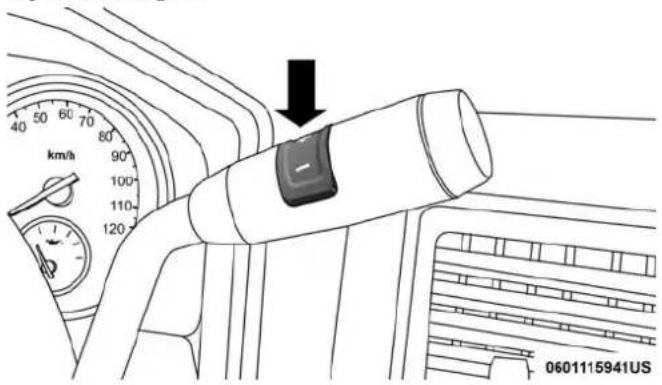
text_image
40 60 70 80 90 100 110 120 km/h 0601115941USElectronicRangeSelect
To exit ERS mode, simply push and hold the ERS (+) switch until the gear limit display disappears from the instrument cluster.

WARNING!
Donotdownshiftforadditionalenginebrakingona slipperysurface. Thedrivewheelscouldlosetheirgrip andthevehiclecouldskid,causingacollisionor personalinjury.
NOTE: To select the proper gear position for maximum deceleration (engine braking), simply push and hold the ERS (-) switch. The transmission will shift to the range from which the vehicle can best be slowed down.
CAUTION!
When using ERSforengine braking while descending steep grades, be careful not too overspeed the engine. Apply the brakes as needed to prevent engine over speed.
OverdriveOperation
The automatic transmission includes an electronically controlled Overdrive (fifth and sixth gears). The transmission will automatically shift into Overdrive if the following conditions are present:
- The gear selector is in the DRIVE position.
- The transmission fluid has reached an adequate temperature.
- The engine coolant has reached an adequate temperature.
- Vehicle speed is sufficiently high.
- The TOW/HAUL switch has not been activated.
- The driver is not heavily pressing the accelerator.
260 STARTING AND OPERATING
WhenToUseTOW/HAULMode
When driving in hilly areas, towing a trailer, carrying a heavy load, etc., and frequent transmission shifting occurs, push the TOW/HAUL switch to activate TOW/HAUL mode. This will improve performance and reduce the potential for transmission overheating or failure due to excessive shifting. When operating in TOW/HAUL mode, transmission upshifts are delayed, and the transmission will automatically downshift (for engine braking) when the throttle is closed and/or during steady braking maneuvers.
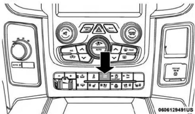
text_image
0606129491USTOW/HAULSwitch
The "TOW/HAUL Indicator Light" will illuminate in the instrument cluster to indicate that TOW/HAUL mode has been activated. Pushing the switch a second time restores normal operation. Normal operation is always the default at engine start-up. If TOW/HAUL mode is desired, the switch must be pushed each time the engine is started.
WARNING!
Donotusethe"TOW/HAUL"featurewhendrivingin icyorslipperyconditions.Theincreasedenginebrakingcancausetherearwheelstoslide,andthevehicle toswingaroundwiththepossiblelossofvehicle control,whichmaycauseanaccidentpossiblyresultinginpersonalinjuryordeath.
TorqueConverterClutch
A feature designed to improve fuel economy has been included in the automatic transmission on your vehicle. A clutch within the torque converter engages automatically at calibrated speeds. This may result in a slightly different feeling or response during normal operation in the upper gears. When the vehicle speed drops or during some accelerations, the clutch automatically disengages.

NOTE:
- The torque converter clutch will not engage (and 66RFE-equipped trucks will not shift to sixth gear), until the transmission fluid and engine coolant are warm [usually after 1 to 3 miles (2 to 5 km) of driving]. Because engine speed is higher when the torque converter clutch is not engaged, it may seem as if the transmission is not shifting properly when cold. This is normal. Using the Electronic Range Select (ERS) shift control, when the transmission is sufficiently warm, will demonstrate that the transmission is able to shift into and out of Overdrive.
- If the vehicle has not been driven for several days, the first few seconds of operation after shifting the transmission into gear may seem sluggish. This is due to the fluid partially draining from the torque converter into the transmission. This condition is normal and will not cause damage to the transmission. The torque converter will refill within five seconds after starting the engine.
Four-wheel drive trucks are equipped with either a manually shifted transfer case or an electronically shifted transfer case. Refer to the operating instructions for your transfer case, located in this section for further information.
Manually Shifted Transfer Case — If Equipped
The transfer case provides four mode positions:
- Two-Wheel Drive High Range (2H)
- Four-Wheel Drive Lock High Range (4H)
• Neutral (N) - Four-Wheel Drive Low Range (4L)
For additional information on the appropriate use of each transfer case mode position, see the information below:
2H
Two-Wheel Drive High Range — This range is for normal street and highway driving on dry, hard surfaced roads.
4H
Four-Wheel Drive Lock High Range — This range locks the front and rear driveshafts together forcing the front and rear wheels to rotate at the same speed. Additional traction for loose, slippery road surfaces only.
NEUTRAL(N)
Neutral — This range disengages both the front and rear driveshafts from the powertrain. To be used for flat towing behind another vehicle. Refer to “Recreational Towing” in “Starting And Operating” for further information.
262 STARTING AND OPERATING
4L
Four-Wheel Drive Low Range — This range locks the front and rear driveshafts together forcing the front and rear wheels to rotate at the same speed. Additional traction and maximum pulling power for loose, slippery road surfaces only. Do not exceed 25 mph (40 km/h).
This transfer case is intended to be driven in the 2H position for normal street and highway conditions such as dry, hard surfaced roads.
When additional traction is required, the 4H and 4L positions can be used to lock the front and rear driveshafts together and force the front and rear wheels to rotate at the same speed. This is accomplished by simply moving the gear selector to the desired positions once the appropriate speed and gear requirements are met, refer to “Shifting Procedure – Manually Shifted Transfer Case” in this section for further information.
The 4H and 4L positions are intended for loose, slippery road surfaces only. Driving in the 4H and 4L positions on dry, hard surfaced roads may cause increased tire wear and damage to the driveline components.
The "Transfer Case Position Indicator Light" in the instrument cluster will alert the driver that the vehicle is in four-wheel drive and that the front and rear driveshafts are locked together. This light will illuminate when the transfer case is shifted into either the 4H or 4L position. There is no light for the 2H or NEUTRAL positions on some models.
When operating your vehicle in 4L, the engine speed is approximately three times that of the 2H or 4H positions at a given road speed. Take care not to overspeed the engine and do not exceed 25 mph (40 km/h).
Proper operation of four-wheel drive vehicles depends on tires of equal size, type and circumference on each wheel. Any difference will adversely affect shifting and can cause damage to the drivetrain.
NOTE: Do not attempt to make a shift while only the front or rear wheels are spinning, as this can cause damage to driveline components.
Because four-wheel drive provides improved traction, there is a tendency to exceed safe turning and stopping speeds. Do not go faster than road conditions permit.
NOTE: Delayed shifts out of four-wheel drive may be experienced due to uneven tire wear, low or uneven tire pressures, excessive vehicle loading, or cold temperatures.

WARNING!
Youorotherscouldbeinjuredorkilledifyouleavethe vehicleunattendedwiththetransfercaseintheNEUTRALpositionwithoutfirstfullyengagingtheparkingbrake.ThetransfercaseNEUTRALpositiondisengagesboththefrontandredriveshaftsfromthe powertrainandwillallowthevehicletoroll,evenif thetransmissionisinPARK.Theparkingbrake shouldalwaysbeappliedwhenthedriverisnotinthe vehicle.
Two-WheelDriveHighRange(2H)
Rear-Wheel Drive High Range — This range is for normal street and highway driving on dry hard surfaced roads.
Four-WheelDriveHighRange(4H)
Four-Wheel Drive High Range — This range locks the front and rear driveshafts together forcing the front and rear wheels to rotate at the same speed. Additional traction for loose, slippery road surfaces only.
Neutral(N)
Neutral — This range disengages the front and rear driveshafts from the powertrain. To be used for flat towing behind another vehicle. Refer to “Recreational Towing” in “Starting And Operating” for further information.
Four-WheelDriveLowRange(4L)
Four-Wheel Drive Low Range — This range locks the front and rear driveshafts together forcing the front and rear wheels to rotate at the same speed. Additional traction and maximum pulling power for loose, slippery road surfaces only. Do not exceed 25 mph (40 km/h).
CAUTION!
Donotuse4L(Low)rangewhenoperatingthevehicle ondrypavement.Drivelinehardwaredamagecan result.
264 STARTING AND OPERATING
ShiftingProcedure—ManuallyShiftedTransfer Case
2HTo4H
Shifting between 2H and 4H can be made with the vehicle stopped or in motion. If the vehicle is in motion, shifts can be made up to 55 mph (88 km/h). With the vehicle in motion, the transfer case will engage/disengage faster if you momentarily release the accelerator pedal after completing the shift. Apply a constant force when shifting the transfer case lever.
2HOr4HTo4L
NOTE: When shifting into or out of 4L some gear noise may be heard. This noise is normal and is not detrimental to the vehicle or occupants.
With the vehicle rolling at 2 to 3 mph (3 to 5 km/h), shift the transmission into NEUTRAL. While the vehicle is coasting at 2 to 3 mph (3 to 5 km/h), shift the transfer case lever firmly to the desired position. Do not pause in transfer case NEUTRAL.
NOTE:
- Pausing in transfer case NEUTRAL in vehicles equipped with an automatic transmission may require shutting the engine OFF to avoid gear clash while completing the shift. If difficulty occurs, shift the transmission into NEUTRAL, hold your foot on the brake, and turn the engine OFF. Complete the range shift to the desired mode.
- Shifting into or out of 4L is possible with the vehicle completely stopped, however difficulty may occur due to the mating clutch teeth not being properly aligned. Several attempts may be required for clutch teeth alignment and shift completion to occur. The preferred method is with the vehicle rolling 2 to 3 mph (3 to 5 km/h). Avoid attempting to engage or disengage 4L with the vehicle moving faster than 2 to 3 mph (3 to 5 km/h).
- Do not attempt to shift into or out of 4L while the transmission is in gear.
TransferCasePositionIndicatorLight
The "Transfer Case Position Indicator Light" in the instrument cluster is used to alert the driver that the front axle is fully engaged and all four wheels are driving.
Electronically Shifted Transfer Case (Four-Position Switch) — If Equipped
The electronic shift transfer case is operated by the 4WD Control Switch (Transfer Case Switch), which is located on the instrument panel.
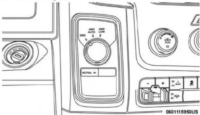
text_image
4WD 4WD AUTO LOW 2WD 0 0 NEUTRAL = 0601115950USFour-Position/PartTimeTransferCase
This electronically shifted transfer case provides four mode positions:
• Two-Wheel Drive High Range (2WD)
• Four-Wheel Drive Lock High Range (4WD LOCK)
• Four-Wheel Drive Low Range (4WD LOW)
• Neutral (NEUTRAL)
For additional information on the appropriate use of each transfer case mode position, see the information below:
2WD
Rear Wheel Drive High Range — This range is for normal street and highway driving on dry, hard surfaced roads.
4WDLOCK
Four-Wheel Drive Lock High Range — This range maximizes torque to the front driveshaft, forcing the front and rear wheels to rotate at the same speed. This range provides additional traction for loose, slippery road surfaces only.
4WDLOW
Four-Wheel Drive Low Range — This range provides low speed four-wheel drive. It maximizes torque to the front driveshaft, forcing the front and rear wheels to rotate at the

266 STARTING AND OPERATING
same speed. This range provides additional traction and maximum pulling power for loose, slippery road surfaces only. Do not exceed 25 mph (40 km/h).
NEUTRAL(N)
Neutral — This range disengages both the front and rear driveshafts from the powertrain. To be used for flat towing behind another vehicle. Refer to “Recreational Towing” in this section for further information.
WARNING!
Youorotherscouldbeinjuredorkilledifyouleavethe vehicleunattendedwiththetransfercaseintheNEUTRALpositionwithoutfirstfullyengagingtheparkingbrake.ThetransfercaseNEUTRALpositiondisengagesboththefrontandreadriveshaftsfromthe powertrainandwillallowthevehicletoroll,evenif thetransmissionisinPARK.Theparkingbrake shouldalwaysbeappliedwhenthedriverisnotinthe vehicle.
This electronically shifted transfer case is designed to be driven in the two-wheel drive position (2WD) for normal street and highway conditions on dry, hard surfaced roads.
When additional traction is required, the transfer case 4WD LOCK and 4WD LOW positions can be used to maximize torque to the front driveshaft, forcing the front and rear wheels to rotate at the same speed. This is accomplished by rotating the 4WD Control Switch to the desired position.
Refer to "Shifting Procedure" in this section for specific shifting instructions.
The 4WD LOCK and 4WD LOW positions are designed for loose, slippery road surfaces only. Driving in the 4WD LOCK and 4WD LOW positions on dry hard surfaced roads may cause increased tire wear and damage to the driveline components.
NOTE: The transfer case NEUTRAL button is located on the lower left hand corner of the 4WD Control Switch. The transfer case NEUTRAL position is to be used for recreational towing only. Refer to "Recreational Towing" in "Starting And Operating" for further information.
TransferCasePositionIndicatorLights
The Transfer Case Position Indicator Lights (4WD and 4LOW) are located in the instrument cluster and indicate the current and desired transfer case selection. When you select a different transfer case position, the indicator lights will do the following:
IfAllOfTheFollowingShiftConditionsAreMet:
- The current position indicator light will turn OFF.
- The selected position indicator light will flash until the transfer case completes the shift.
- When the shift is complete, the indicator light for the selected position will stop flashing and remain ON.
IfOneOrMoreOfTheFollowingShiftConditionsAre NotMet:
- The indicator light for the current position will remain ON.
- The newly selected position indicator light will continue to flash.
- The transfer case willnotshift.
NOTE: Before retrying a selection, make certain that all the necessary requirements for selecting a new transfer case position have been met. To retry the selection, turn the control switch back to the current position, wait five seconds, and retry selection. To find the shift requirements, refer to the "Shifting Procedure" for your transfer case, located in this section.
The “SVC 4WD Warning Light” monitors the electronic shift four-wheel drive system. If this light remains on after engine start up or illuminates during driving, it means that the four-wheel drive system is not functioning properly and that service is required.
WARNING!
Alwaysengagetheparkingbrakewhenpowering downthevehicleifthe"SVC4WDWarningLight"is illuminated. Notengagingtheparkingbrakemay allowthevehicletoroll,whichmaycausepersonal injury.
NOTE: Do not attempt to make a shift while only the front or rear wheels are spinning, as this can cause damage to driveline components.
268 STARTING AND OPERATING
When operating your vehicle in 4WD LOW, the engine speed is approximately three times that of the 2WD or 4WD LOCK positions at a given road speed. Take care not to overspeed the engine and do not exceed 25 mph (40 km/h).
Proper operation of four-wheel drive vehicles depends on tires of equal size, type and circumference on each wheel. Any difference in tire size can cause damage to the drivetrain.
Because four-wheel drive provides improved traction, there is a tendency to exceed safe turning and stopping speeds. Do not go faster than road conditions permit.
ShiftingProcedure
NOTE:
- If any of the requirements to select a new transfer case position have not been met, the transfer case will not shift. The position indicator light for the previous position will remain ON and the newly selected position indicator light will continue to flash until all the requirements for the selected position have been met. To retry a shift: return the control switch back to the original position, make certain all shift requirements have been met, wait five seconds and try the shift again.
- If all the requirements to select a new transfer case position have been met, the current position indicator light will turn OFF, the selected position indicator light will flash until the transfer case completes the shift. When the shift is complete, the position indicator light for the selected position will stop flashing and remain ON.

2WDTo4WDLOCK
Rotate the 4WD control switch to the desired position. Shifts between 2WD and 4WD LOCK can be done with the vehicle stopped or in motion. With the vehicle in motion, the transfer case will engage/disengage faster if you momentarily release the accelerator pedal after turning the control switch. If the vehicle is stopped, the ignition switch must be in the ON position with the engine either running or off. This shift cannot be completed if the ignition switch is in the ACC position.
NOTE: The four-wheel drive system will not allow shifts between 2WD/4WD LOCK if the front and/or rear wheels are spinning (no traction). In this situation, the selected position indicator light will flash and the original position indicator light will remain ON. At this time, reduce speed and stop spinning the wheels to complete the shift.
2WDOr4WDLOCKTo4WDLOW
NOTE: When shifting into or out of 4WD LOW some gear noise may be heard. This noise is normal and is not detrimental to the vehicle or occupants.
Shifting can be performed with the vehicle rolling 2 to 3 mph (3 to 5 km/h) or completely stopped. You can use either of the following procedures:
PreferredProcedure
- With the engine running, slow the vehicle to 2 to 3 mph (3 to 5 km/h).
- Shift the transmission into NEUTRAL.
- While still rolling, rotate the transfer case control switch to the desired position.
- After the desired position indicator light is ON (not flashing), shift the transmission back into gear.
AlternateProcedure
- Bring the vehicle to a complete stop.
- With the ignition switch in the ON position and the engine running, shift the transmission into NEUTRAL.
- Rotate the transfer case control switch to the desired position.
- After the desired position indicator light is ON (not flashing), shift the transmission back into gear.

270 STARTING AND OPERATING
NOTE:
- If Steps 1 or 2 of either the Preferred or Alternate Procedure are not satisfied prior to attempting the shift, then the desired position indicator light will flash continuously while the original position indicator light is ON, until all requirements have been met.
- The ignition switch must be in the ON position for a shift to take place and for the position indicator lights to be operable. If the ignition switch is not in the ON position, the shift will not take place and no position indicator lights will be on or flashing.
LIMITED-SLIP DIFFERENTIAL
The limited-slip differential provides additional traction on snow, ice, mud, sand and gravel, particularly when there is a difference between the traction characteristics of the surface under the right and left rear wheels. During normal driving and cornering, the limited-slip unit performs similarly to a conventional differential. On slippery surfaces, however, the differential delivers more of the driving effort to the rear wheel having the better traction.
The limited-slip differential is especially helpful during slippery driving conditions. With both rear wheels on a slippery surface, a slight application of the accelerator will supply maximum traction. When starting with only one rear wheel on an excessively slippery surface, slight momentary application of the parking brake may be necessary to gain maximum traction.
WARNING!
Onvehiclesequippedwithalimited-slipdifferential neverruntheenginewithonerearwheeloffthe groundsincethevehiclemaydrivethroughtherear wheelremainingontheground.Youcouldlosecontrol ofthevehicle.
Care should be taken to avoid sudden accelerations when both rear wheels are on a slippery surface. This could cause both rear wheels to spin, and allow the vehicle to slide sideways on the crowned surface of a road or in a turn.
This vehicle when equipped with PTO Prep and the AS66RC automatic six-speed, will allow for an aftermarket upfit with a transmission driven PTO (power take off). The customer will have the ability to operate the PTO in either a “stationary” or “mobile” mode. The vehicles will be factory set to the “stationary” mode. To select “mobile”
mode, you will need to enter the commercial vehicle menu on the instrument cluster screen and select mobile PTO mode. Details of the PTO selection modes and further PTO information is available at the Ram Truck Bodybuilders web site: www.rambodybuilder.com.
AS66RCSix-SpeedAutomaticTransmissionOnly
The PTO drive gear (part of the AS66RC) operates at torque converter turbine speed. The turbine speed will be less than engine speed when the torque converter clutch is not engaged and will be same as engine speed when the torque converter clutch is engaged.
Stationary Mode
To operate the PTO in this mode the vehicle must meet the following conditions:
- Transmission in PARK position (vehicles equipped with automatic transmission.)
- PTO switch has been activated.
- Parking brake applied (vehicles equipped with manual transmission).
- Brake pedal must not be applied.
-
Vehicle engine must be running.
-
No vehicle, brake or clutch switch faults present.
- PTO must be correctly installed using the vehicle provided circuits.
The instrument cluster will display a "PTO On" message for five seconds if the above conditions are met. Otherwise, the instrument cluster will display a message "To Operate PTO Shift To Park" indicating what operator action should be taken to engage the PTO mode.
The customer has the choice to operate the PTO by utilizing the cruise control switches or by utilizing a remote control (provided by the PTO supplier). To operate the feature using the cruise control switches, the customer must first activate the PTO switch which will turn on the PTO. In order to increase or decrease the engine idle speed, to optimize the PTO function, the "RESUME/ACCEL" and "DECEL" cruise switches can be used respectively. To disengage PTO operation and return to "standard vehicle operation" simply toggle the PTO switch to the OFF position.
The torque converter clutch (TCC) will automatically engage at engine speeds above 1,200 RPM (engine speed) in PTO stationary mode. Once engaged, the TCC will remain applied and will not disengage until the engine speed falls

272 STARTING AND OPERATING
below 1,000 RPM. TCC engagement is desirable for certain types of PTO applications (Automatic Transmission Only).
To operate the PTO via a remote switch, the customer must make sure the above conditions are met. It is vital for proper operation that the PTO and remote have been installed correctly, paying special attention to ensure the vehicle provided wiring has been connected properly. This is the responsibility of the installer of the PTO and switches/remote system. It is the responsibility of the PTO manufacturer to ensure that their electrical (switches and remote) system is compatible with the vehicle's electrical architecture and software functionality.
NOTE: Single set speed can be programmed via the PTO menu on the instrument cluster display. Further details are available at the Ram Truck Bodybuilders web site located at rambodybuilder.com
Mobile Mode
To operate the PTO in this mode the vehicle must meet the following conditions:
- Mobile mode is activated via the menu on the instrument cluster display.
•(ON/OFF) switch has been activated.
- Vehicles with automatic transmission must be in PARK or DRIVE.
- Parking brake must not be applied.
- Brake pedal must not be applied.
- No vehicle, brake or clutch switch faults present.
- Vehicle engine must be running.
- PTO must be correctly installed using the vehicle provided circuits.
The customer may choose to use the PTO while the vehicle is moving. To do so, the PTO function must be activated prior to taking the vehicle out of PARK. This is accomplished by activating the upfitter-provided PTO on/off switch. At this point, the customer may place the vehicle in a forward or reverse gear and have PTO operation once the vehicle begins to move. To disengage PTO operation and return to “standard vehicle operation” simply toggle the on/off switch to the OFF position.

NOTE: For application specific information with respect to PTO and pump requirements and additional vehicle information (wiring schematics, preset idle values, engine speed limits, and vehicle hardware and software requirements) please refer to the Body Builders Guide by accessing rambodybuilder.comandchoosingtheappropriate links.
POWER STEERING
Hydraulic Power Steering
The standard power steering system will give you good vehicle response and increased ease of maneuverability in tight spaces. The system will provide mechanical steering capability if power assist is lost.
If for some reason the power assist is interrupted, it will still be possible to steer your vehicle. Under these conditions, you will observe a substantial increase in steering effort, especially at very low vehicle speeds and during parking maneuvers.
NOTE:
- Increased noise levels at the end of the steering wheel travel are considered normal and do not indicate that there is a problem with the power steering system.
- Upon initial start-up in cold weather, the power steering pump may make noise for a short amount of time. This is due to the cold, thick fluid in the steering system. This noise should be considered normal, and it does not in any way damage the steering system.
CAUTION!
Prolongedoperationofthesteeringsystemattheend ofthesteeringwheeltravelwillincreasethesteering fluidtemperatureanditshouldbeavoidedwhen possible.Damagetothepowersteeringpumpmay occur.
PowerSteeringFluidCheck
Checking the power steering fluid level at a defined service interval is not required. The fluid should only be checked if a leak is suspected, abnormal noises are apparent, and/or the system is not functioning as anticipated. Check

fluid level when the engine is cold and off. Coordinate inspection efforts through an authorized dealer.
WARNING!
Fluidlevelshouldbecheckedonalevelsurfaceand withtheengineofftopreventinjuryfrommoving partsandtoensureaccuratefluidlevelreading.Donot overfill.Useonlymanufacturer'srecommendedpower steeringfluid.
CAUTION!
Donotusechemicalflushesinyourpowersteering systemasthechemicalscandamageyourpowersteeringcomponents.Suchdamageisnotcoveredbythe NewVehicleLimitedWarranty.
If necessary, add fluid to restore to the proper indicated level. With a clean cloth, wipe any spilled fluid from all surfaces. Refer to "Fluids And Lubricants" in "Technical Specifications" for further information.
SPEED CONTROL
When engaged, the Speed Control takes over accelerator operations at speeds greater than 25 mph (40 km/h). The Speed Control buttons are located on the right side of the steering wheel.

text_image
GEAR - GEAR + ON/OFF RES + CANCEL SET - SpeedControlButtons 0322115793US1 — ON/OFF 3 — SET (-) 2 — RES (+) 4 — CANCEL
NOTE: In order to ensure proper operation, the Speed Control System has been designed to shut down if multiple speed control functions are operated at the same time. If this occurs, the Speed Control System can be reactivated by pushing the Speed Control ON/OFF button and resetting the desired vehicle set speed.
To Activate
Push the ON/OFF button. The Cruise Indicator Light in the instrument cluster display will illuminate. To turn the system off, push the ON/OFF button a second time. The Cruise Indicator Light will turn off. The system should be turned off when not in use.
WARNING!
LeavingtheSpeedControlsystemonwhennotinuse isdangerous.Youcouldaccidentallysetthesystemor causeittogofasterthanyouwant.Youcouldlose controlandhaveanaccident.Alwaysleavethesystem offwhenyouarenotusingit.
To Set A Desired Speed
Turn the Speed Control on. When the vehicle has reached the desired speed, push the SET (-) button and release. Release the accelerator and the vehicle will operate at the selected speed.
NOTE: The vehicle should be traveling at a steady speed and on level ground before pushing the SET (-) button.
To Vary The Speed Setting
ToIncreaseSpeed
When the Speed Control is set, you can increase speed by pushing the RES (+) button.
The driver's preferred units can be selected through the instrument panel settings if equipped. Refer to "Getting To Know Your Instrument Panel" for more information. The speed decrement shown is dependant on the chosen speed unit of U.S. (mph) or Metric (km/h):
U.S.Speed(mph)
- Pushing the RES (+) button once will result in a 1 mph increase in set speed. Each subsequent tap of the button results in an increase of 1 mph.
- If the button is continually pushed, the set speed will continue to increase until the button is released, then the new set speed will be established.
MetricSpeed(km/h)
- Pushing the RES (+) button once will result in a 1 km/h increase in set speed. Each subsequent tap of the button results in an increase of 1 km/h.

276 STARTING AND OPERATING
- If the button is continually pushed, the set speed will continue to increase until the button is released, then the new set speed will be established.
ToDecreaseSpeed
When the Speed Control is set, you can decrease speed by pushing the SET (-) button.
The driver's preferred units can be selected through the instrument panel settings if equipped. Refer to "Getting To Know Your Instrument Panel" for more information. The speed decrement shown is dependant on the chosen speed unit of U.S. (mph) or Metric (km/h):
U.S.Speed(mph)
- Pushing the SET (-) button once will result in a 1 mph decrease in set speed. Each subsequent tap of the button results in a decrease of 1 mph.
- If the button is continually pushed, the set speed will continue to decrease until the button is released, then the new set speed will be established.
MetricSpeed(km/h)
- Pushing the SET (-) button once will result in a 1 km/h decrease in set speed. Each subsequent tap of the button results in a decrease of 1 km/h.
- If the button is continually pushed, the set speed will continue to decrease until the button is released, then the new set speed will be established.
To Accelerate For Passing
Press the accelerator as you would normally. When the pedal is released, the vehicle will return to the set speed.
UsingSpeedControlOnHills
The transmission may downshift on hills to maintain the vehicle set speed.
NOTE: The Speed Control system maintains speed up and down hills. A slight speed change on moderate hills is normal.
On steep hills, a greater speed loss or gain may occur so it may be preferable to drive without Speed Control.
WARNING!
SpeedControlcanbedangerouswherethesystem cannotmaintinaconstantspeed.Yourvehiclecould gotoofastfortheconditions,andyoucouldlose controlandhaveanaccident.DonotuseSpeedControl inheavytrafficoronroadsthatarewinding,icy, snow-coveredorslippery.

To Resume Speed
To resume a previously set speed, push the RES (+) button and release. Resume can be used at any speed above 20 mph (32 km/h).
To Deactivate
A soft tap on the brake pedal, pushing the CANCEL button, or normal brake pressure while slowing the vehicle will deactivate the Speed Control without erasing the set speed from memory.
Pushing the ON/OFF button, or returning the ignition to OFF, erases the set speed from memory.
PARKSENSE REAR PARK ASSIST — IF EQUIPPED
The ParkSense Rear Park Assist system provides visual and audible indications of the distance between the rear fascia and a detected obstacle when backing up, e.g. during a parking maneuver. Refer to “ParkSense System Usage Precautions” in this section for limitations of this system and recommendations.
ParkSense will retain the last system state (enabled or disabled) from the last ignition cycle when the ignition is changed to the ON/RUN position.
ParkSense can be active only when the gear selector is in REVERSE. If ParkSense is enabled at this gear selector position, the system will remain active until the vehicle speed is increased to approximately 7 mph (11 km/h) or above. When in REVERSE and above the system's operating speed, a warning will appear within the instrument cluster display indicating the vehicle speed is too fast. The system will become active again if the vehicle speed is decreased to speeds less than approximately 6 mph (9 km/h).
ParkSense Sensors
For the 3500, 4500 and 5500 Chassis Cab vehicles, the rear ParkSense sensors are shipped loose. Please refer to the Ram Body Builders Guide for more information.
The four ParkSense sensors, located in the rear fascia/bumper, monitor the area behind the vehicle that is within the sensors' field of view. The sensors can detect obstacles from approximately 18 inches (45 cm) up to 79 inches (200 cm) from the rear fascia/bumper in the horizontal direction, depending on the location, type and orientation of the obstacle.

278 STARTING AND OPERATING
ParkSense Warning Display
The ParkSense Warning screen is located within the instrument cluster display. It provides visual warnings to indicate the distance between the rear fascia/bumper and the detected obstacle. Refer to "Instrument Cluster Display" in "Getting To Know Your Instrument Panel" for further information.
The ParkSense Warning screen will only be displayed if "Sound and Display" is selected.
NOTE: This feature can be programmed through the Uconnect system. Refer to "Uconnect Settings" in "Multimedia" for further information.
ParkSense Display
When the vehicle is in REVERSE, the warning display will turn on indicating the system status.
The system will indicate a detected obstacle by showing a single arc in the left and/or right rear regions based on the object's distance and location relative to the vehicle.
If an object is detected in the left and/or right rear region, the display will show a single solid arc in the left and/or right rear region and the system will produce a tone. As the vehicle moves closer to the object, the display will show the single arc moving closer to the vehicle and the tone will change from a single 1/2 second tone to slow, to fast, to continuous.

text_image
PRNDSingle1/2SecondTone
032771343

text_image
PRND032771342
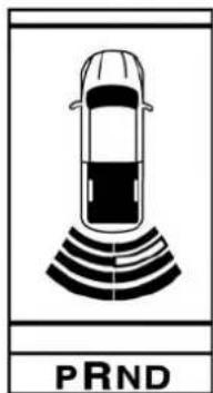
text_image
PRND032771344
SlowToneFastTone

text_image
PRNDContinuousTone
The vehicle is close to the obstacle when the warning display shows one flashing arc and sounds a continuous tone. The following chart shows the warning alert operation when the system is detecting an obstacle:
032771345
| WARNINGALERTS | |||||
| Rear Distance (inches/cm) | Greater than 79 inches (200 cm) | 79-45 inches (200-115 cm) | 45-31 inches (115-80 cm) | 31-18 inches (80-45 cm) | Less than 18 inches (45 cm) |
| Audible Alert Chime | None Single | 1/2 Second Tone | Slow Fast Continuous | ||
| Arc None 4th Solid 3rd | Solid | 2nd Flashing | 1st Flashing | ||
| Radio Volume Reduced | No Yes Yes | Yes Yes | |||

NOTE: ParkSense will reduce the volume of the radio, if on, when the system is sounding an audio tone.
AdjustableChimeVolumeSettings
The rear chime volume settings are programmable.
- The settings may be programmed through the Uconnect System. Refer to "Uconnect Settings" in "Multimedia" for further information.
Enabling And Disabling ParkSense
ParkSense can be enabled and disabled with the ParkSense switch.

When the ParkSense switch is pushed to disable the system, the instrument cluster will display the "PARKSENSE OFF" message for approximately five seconds. Refer to "Instrument Cluster Display" in "Getting To Know Your Instrument Panel" for further information. When the gear selector is moved to REVERSE and the system is disabled, the instrument cluster display will show the "PARKSENSE OFF" message for as long as the vehicle is in REVERSE.
NOTE: The ParkSense system will automatically disable when the system detects that a trailer with trailer brakes has been connected to the Integrated Trailer Brake Module. The instrument cluster display will show the "PARKSENSE OFF" message for as long as the vehicle is in reverse.
The ParkSense switch LED will be on when ParkSense is disabled or defective. The ParkSense switch LED will be off when the system is enabled.
If the ParkSense switch is pushed, and the system is disabled or requires service, the ParkSense switch LED will blink momentarily, and then the LED will be on.
Service The ParkSense Rear Park Assist System
During vehicle start up, when the ParkSense Rear Park Assist System has detected a faulted condition, the instrument cluster display will actuate a single chime, once per ignition cycle, and it will show the "PARKSENSE UNAVAILABLE WIPE REAR SENSORS" or the "PARKSENSE UNAVAILABLE SERVICE REQUIRED" message. Refer to "Instrument Cluster Display" in "Getting To Know Your Instrument Panel" for further information. When the gear selector is moved to REVERSE and the system has detected a faulted condition, the instrument cluster display will

show the "PARKSENSE UNAVAILABLE WIPE REAR SENSORS" or the "PARKSENSE UNAVAILABLE SERVICE REQUIRED" message for as long as the vehicle is in REVERSE. Under this condition, ParkSense will not operate.
If "PARKSENSE UNAVAILABLE WIPE REAR SENSORS" appears in the instrument cluster display make sure the outer surface and the underside of the rear fascia/bumper is clean and clear of snow, ice, mud, dirt or other obstruction, and then cycle the ignition. If the message continues to appear, see your authorized dealer.
If "PARKSENSE UNAVAILABLE SERVICE REQUIRED" appears in the instrument cluster display, see your authorized dealer.
Cleaning The ParkSense System
Clean the ParkSense sensors with water, car wash soap and a soft cloth. Do not use rough or hard cloths. Do not scratch or poke the sensors. Otherwise, you could damage the sensors.
ParkSense System Usage Precautions
NOTE:
- Ensure that the rear bumper is free of snow, ice, mud, dirt and debris to keep the ParkSense system operating properly.
- Jackhammers, large trucks, and other vibrations could affect the performance of ParkSense.
- When you turn ParkSense off, the instrument cluster display will show "PARKSENSE OFF". Furthermore, once you turn ParkSense off, it remains off until you turn it on again, even if you cycle the ignition key.
- When you move the gear selector to the REVERSE position and ParkSense is turned off, the instrument cluster display will show the "PARKSENSE OFF" message for as long as the vehicle is in REVERSE.
- ParkSense, when on, will reduce the volume of the radio when it is sounding a tone.
- Clean the ParkSense sensors regularly, taking care not to scratch or damage them. The sensors must not be covered with ice, snow, slush, mud, dirt or debris. Failure to do so can result in the system not working properly. The ParkSense system might not detect an
obstacle behind the fascia/bumper, or it could provide a false indication that an obstacle is behind the fascia/bumper.
- Ensure the ParkSense system is OFF if objects such as bicycle carriers, trailer hitches, etc., are placed within 18 inches (45 cm) from the rear fascia/bumper while driving the vehicle. Failure to do so can result in the system misinterpreting a close obstacle as a sensor problem, causing the "PARKSENSE UNAVAILABLE SERVICE REQUIRED" message to appear in the instrument cluster display.
- On vehicles equipped with a tailgate, ParkSense should be disabled when the tailgate is in the lowered or open position and the vehicle is in REVERSE. A lowered tailgate could provide a false indication that an obstacle is behind the vehicle.
WARNING!
- Driversmustbecarefulwhenbackingupevenwhen usingParkSense.Alwayscheckcarefullybehind yourvehicle,lookbehindyou,andbesuretocheck forpedestrians,animals,othervehicles,obstructions,
WARNING!(Continued)
andblindspotsbeforebackingup.Youareresponsibleforsafetyandmustcontinuetopayattentionto yoursurroundings.Failureretodosocanresultin seriousinjuryordeath.
- BeforeusingParkSense,itisstronglyrecommended thattheballmountandhitchballassemblyis disconnectedfromthevehiclewhenthevehicleisnotusedfor towing.Failureretodosocanresultininjuryordamage to vehicles or obstacles because the hitch ball will be muchclosertotheobstaclethantherearfasciawhenthe loudspeakersoundsthecontinuoustone.Also,the sensorscoulddetecttheballmountandhitchball assembly,dependingonitssizeandshape,givinga falseindicationthatanobstacleisbehindthevehicle.
CAUTION!
- ParkSenseisonyaparkingaidanditisunableto recognize every obstacle, including small obstacles. Parkingcurbsmightbetemporarilydetectedornot detectedatall.Obstacleslocatedaboveorbelowthe sensorswillnotbedetectedwhentheyareinclose proximity.
CAUTION!(Continued)
• The vehicle must bedrivenslowly when using ParkSense in order to be able to stop in tim when an obstacle is detected. It is recommended that the driver look so over his /hers shoulder when using ParkSense.
PARKSENSE FRONT AND REAR PARK ASSIST — IF EQUIPPED
The ParkSense Park Assist system provides visual and audible indications of the distance between the rear and/or front fascia and a detected obstacle when backing up or moving forward, e.g. during a parking maneuver. Refer to "ParkSense System Usage Precautions" in this section for limitations of this system and recommendations.
ParkSense will retain the last system state (enabled or disabled) from the last ignition cycle when the ignition is changed to the ON/RUN position.
ParkSense can be active only when the gear selector is in REVERSE or DRIVE. If ParkSense is enabled at one of these gear selector positions, the system will remain active until the vehicle speed is increased to approximately 7 mph (11 km/h) or above. A warning will appear in the instrument cluster display indicating the vehicle is above ParkSense operating speed. The system will become active again if the vehicle speed is decreased to speeds less than approximately 6 mph (9 km/h).
ParkSense Sensors
For the 3500, 4500 and 5500 Chassis Cab vehicles, the rear ParkSense sensors are shipped loose. Please refer to the Ram Body Builders Guide for more information.
The four ParkSense sensors, located in the rear fascia/bumper, monitor the area behind the vehicle that is within the sensors' field of view. The sensors can detect obstacles from approximately 18 inches (45 cm) up to 79 inches (200 cm) from the rear fascia/bumper in the horizontal direction, depending on the location, type and orientation of the obstacle.
The six ParkSense sensors, located in the front fascia/bumper, monitor the area in front of the vehicle that is within the sensors' field of view. The sensors can detect obstacles from approximately 12 inches (30 cm) up to 47 inches (120 cm) from the front fascia/bumper in the horizontal direction, depending on the location, type and orientation of the obstacle.

ParkSense Warning Display
The ParkSense Warning screen is located within the instrument cluster display. It provides visual warnings to indicate the distance between the rear fascia/bumper and/or front fascia/bumper and the detected obstacle. Refer to "Instrument Cluster Display" in "Getting To Know Your Instrument Panel" for further information.
The ParkSense Warning screen will only be displayed if "Sound and Display" is selected.
NOTE: This feature can be programmed through the Uconnect system. Refer to "Uconnect Settings" in "Multimedia" for further information.
ParkSense Display
The warning display will turn on indicating the system status when the vehicle is in REVERSE or when the vehicle is in DRIVE and an obstacle has been detected.
The system will indicate a detected obstacle by showing a single arc in the left and/or right rear regions based on the obstacle's distance and location relative to the vehicle.
If an obstacle is detected in the left and/or right rear region, the display will show a single arc in the left and/or right rear region and the system will produce a tone. As the vehicle moves closer to the obstacle, the display will show the single arc moving closer to the vehicle and the tone will change from a single 1/2 second tone to slow, to fast, to continuous.

The vehicle is close to the obstacle when the display shows one flashing arc and sounds a continuous tone. The following chart shows the warning alert operation when the system is detecting an obstacle:
| WARNINGALERTS | |||||
| Rear Distance (inches/cm) | Greater than 79 inches (200 cm) | 79-45 inches (200-115 cm) | 45-31 inches (115-80 cm) | 31-18 inches (80-45 cm) | Less than 18 inches (45 cm) |
| Front Distance (inches/cm) | Greater than 47 inches (120 cm) | 47-39 inches (120-100 cm) | 39-25 inches (100-65 cm) | 25-12 inches (65-30 cm) | Less than 12 inches (30 cm) |
| Audible Alert (Chime) | None Single | 1/2 Second Tone (for rear only) | Slow (for rear only) | Fast Continuous | |
| Arcs None 4th Solid 3rd Solid 2nd Flashing 1st Flashing | |||||
| Radio Volume Reduced | No Yes Yes | Yes | Yes | ||
NOTE: ParkSense will reduce the volume of the radio, if on, when the system is sounding an audio tone.
FrontParkAssistAudibleAlerts
ParkSense will turn off the Front Park Assist audible alert (chime) after approximately three seconds when an obstacle has been detected, the vehicle is stationary, and brake pedal is applied.
AdjustableChimeVolumeSettings
The Front and Rear chime volume settings are programmable.
- The settings may be programmed through the Uconnect System. Refer to "Uconnect Settings" in "Multimedia" for further information.
Enabling And Disabling Front And/Or Rear ParkSense
Front ParkSense can be enabled and disabled with the Front ParkSense switch.
Rear ParkSense can be enabled and disabled with the Rear ParkSense switch.

When the Front or Rear ParkSense switch is pushed to disable the system, the instrument cluster display will show the "PARKSENSE OFF" message for approximately five seconds.
Refer to "Instrument Cluster Display" in "Getting To Know Your Instrument Panel" for further information.
When the gear selector is moved to REVERSE and the Front or Rear system is disabled, the instrument cluster display will show the "FRONT PARKSENSE OFF" or "REAR PARKSENSE OFF" message for five seconds, followed by a vehicle graphic with "OFF" in the corresponding side. This vehicle graphic will be displayed for as long as the vehicle is in REVERSE.
NOTE: Arc alerts from the enabled ParkSense system, will interrupt the five second messages, and the instrument cluster display will show the vehicle graphic with the corresponding arcs and "OFF" message.
The Front or Rear ParkSense switch LED will be on when Front or Rear ParkSense is disabled or requires service. The Front or Rear ParkSense switch LED will be off when the Front or Rear system is enabled. If the Front or Rear ParkSense switch is pushed, and the system requires service, the Front or Rear ParkSense switch LED will blink momentarily, and then the LED will be on.

Service The ParkSense Park Assist System
During vehicle start up, when the ParkSense System has detected a faulted condition, the instrument cluster will actuate a single chime, once per ignition cycle, and it will display the "PARKSENSE UNAVAILABLE WIPE REAR SENSORS", "PARKSENSE UNAVAILABLE WIPE FRONT SENSORS", or the "PARKSENSE UNAVAILABLE SERVICE REQUIRED" message for five seconds. When the gear selector is moved to REVERSE and the system has detected a faulted condition, the instrument cluster display will display a "PARKSENSE UNAVAILABLE WIPE REAR SENSORS", "PARKSENSE UNAVAILABLE WIPE FRONT SENSORS" or "PARKSENSE UNAVAILABLE SERVICE REQUIRED" pop up message for five seconds. After five seconds, a vehicle graphic will be displayed with "UNAVAILABLE" at either the front or rear sensor location depending on where the fault is detected. The system will continue to provide arc alerts for the side that is functioning properly. These arc alerts will interrupt the "PARKSENSE UNAVAILABLE WIPE REAR SENSORS", "PARKSENSE UNAVAILABLE WIPE FRONT SENSORS", or "PARKSENSE UNAVAILABLE SERVICE REQUIRED" messages if an object is detected within the five second pop-up duration. The vehicle graphic will remain displayed for as long as the vehicle is in REVERSE.
Refer to "Instrument Cluster Display" in "Getting To Know Your Instrument Panel" for further information.
If "PARKSENSE UNAVAILABLE WIPE REAR SENSORS" or "PARKSENSE UNAVAILABLE WIPE FRONT SENSORS" appears in the instrument cluster display make sure the outer surface and the underside of the rear fascia/bumper and/or front fascia/bumper is clean and clear of snow, ice, mud, dirt or other obstruction and then cycle the ignition. If the message continues to appear see your authorized dealer.
If the "PARKSENSE UNAVAILABLE SERVICE REQUIRED" message appears in the instrument cluster display, see your authorized dealer.
Cleaning The ParkSense System
Clean the ParkSense sensors with water, car wash soap and a soft cloth. Do not use rough or hard cloths. Do not scratch or poke the sensors. Otherwise, you could damage the sensors.

ParkSense System Usage Precautions
NOTE:
- Ensure that the front and rear bumper are free of snow, ice, mud, dirt and debris to keep the ParkSense system operating properly.
- Jackhammers, large trucks, and other vibrations could affect the performance of ParkSense.
- When you turn Front or Rear ParkSense off, the instrument cluster display will read "FRONT PARKSENSE OFF" or "REAR PARKSENSE OFF." Furthermore, once you turn Front or Rear ParkSense off, it remains off until you turn it on again, even if you cycle the ignition key.
-
When you move the gear selector to the REVERSE position and Front or Rear ParkSense is turned off, the instrument cluster display will show the "FRONT PARKSENSE OFF" or "REAR PARKSENSE OFF" message for five seconds, followed by a vehicle graphic with "OFF" in the corresponding side. This vehicle graphic will be displayed for as long as the vehicle is in REVERSE.
-
ParkSense, when on, will reduce the volume of the radio when it is sounding a tone.
- Clean the ParkSense sensors regularly, taking care not to scratch or damage them. The sensors must not be covered with ice, snow, slush, mud, dirt or debris. Failure to do so can result in the system not working properly. The ParkSense system might not detect an obstacle behind or in front of the fascia/bumper, or it could provide a false indication that an obstacle is behind or in front of the fascia/bumper.
- Use the ParkSense switch to turn the ParkSense system off if obstacles such as bicycle carriers, trailer hitches, etc. are placed within 18 inches (45 cm) from the rear fascia/bumper. Failure to do so can result in the system misinterpreting a close obstacle as a sensor problem, causing the "PARKSENSE UNAVAILABLE SERVICE REQUIRED" message to be appear in the instrument cluster display.
- On vehicles equipped with a tailgate, ParkSense should be disabled when the tailgate is in the lowered or open position. A lowered tailgate could provide a false indication that an obstacle is behind the vehicle.
WARNING!
- Driversmustbecarefulwhenbackingupevenwhen usingParkSense.Alwayscheckcarefullybehind yourvehicle,lookbehindyou,andbesuretocheck forpedestrians,animals,othervehicles,obstructions, andblindspotsbeforebackingup.Youareresponsibleforsafetyandmustcontinuetopayattentionto yoursurroundings.Failurertodosocanresultin seriousinjuryordeath.
- BeforeusingParkSense,itisstronglyrecommended thattheballmountandhitchballassemblyis disconnectedfromthevehiclewhenthevehicleis notusedfortowing.Failureretodosocanresultin injuryordamagetovehiclesorobstaclesbecausethe hitchballwillbemuchclosertotheobstaclethanthe rearfasciawhentheloudspeakersoundsthecontinuoustone.Also,thesensorscoulddetecttheball mountandhitchballassembly,dependingonitssize andshape,givingafalseindicationthatanobstacle isbehindthevehicle.
CAUTION!
- ParkSenseisonyaparkingaidanditisunableto recognizeeveryobstacle, includingsmallobstacles. Parkingcurbsmightbetemporarilydetectedornot detectedatall.Obstacleslocatedaboveorbelowthe sensorswillnotbedetectedwhentheyareinclose proximity.
- The vehicle must bedrivenslowly when using ParkSense in order to be able to stop in tim when an obstacle is detected. It is recommended that the driver look over his /hers shoulder when using ParkSense.
PARKVIEW REAR BACK UP CAMERA — IF EQUIPPED
Your vehicle may be equipped with the ParkView Rear Back Up Camera that allows you to see a image of the rear surroundings of your vehicle whenever the gear selector is put into REVERSE or whenever it is initiated through the "Backup Camera" button in the "Controls" menu. Whenever the gear selector is put into REVERSE, the image will be displayed in the rearview mirror display (if equipped) or
Uconnect screen (if equipped) along with a caution note to "check entire surroundings" across the top of the screen. After five seconds this note will disappear.
NOTE: For the 3500, 4500 and 5500 Chassis Cab vehicles, the Rear Backup Camera is shipped loose and not installed. Please refer to the Ram Body Builders Guide for more information.
The ParkView Camera is located to the left of the tailgate handle.
When the vehicle is shifted out of REVERSE (with Camera delay turned off), the rear Camera mode is exited and the navigation or audio screen appears again.
When the vehicle is shifted out of REVERSE (with Camera delay turned on), the rear Camera image will be displayed for up to 10 seconds after shifting out of REVERSE unless the forward vehicle speed exceeds 8 mph (13 km/h), the transmission is shifted into PARK or the ignition is switched to the OFF position.
Whenever the Rear View Camera image is activated through the "Backup Camera" button in the "Controls" menu, a display timer for the image is initiated. The image will continue to be displayed until the display timer exceeds 10 seconds and the vehicle speed is above 8 mph (13 km/h) or the touchscreen button "X" to disable display of the Rear View Camera image is pressed.
NOTE: If the vehicle speed remains below 8 mph (13 km/h), the Rear View Camera image will be displayed continuously until deactivated via the touchscreen button "X".
IfEquipped—CargoCameraIcons:
- — Backup Camera Touchscreen Button
• — Cargo Camera Touchscreen Button
If equipped with a Cargo Camera, a touchscreen button
→ to indicate the current active Camera image being displayed is made available whenever the Rear View Camera image is displayed.
If equipped with a Cargo Camera, a touchscreen button
to switch the display to Cargo Camera image is made available whenever the Rear View Camera image is displayed.
A touchscreen button "X" to disable display of the camera image is made available when the vehicle is not in RE-VERSE gear.

When enabled, active guide lines are overlaid on the image to illustrate the width of the vehicle and its projected backup path based on the steering wheel position. The active guide lines will show separate zones that will help indicate the distance to the rear of the vehicle.
NOTE: For further information about how to access and change the programmable features of the ParkView Rear Backup Camera, refer to "Uconnect Settings" in "Multimedia" for further information.
The following table shows the approximate distances for each zone:
| ZonesDistanceTo | TheRearOfTheVehicle |
| Red 0 - 1 ft (0 - 30 cm) | |
| Yellow 1 ft - 6.5 ft (30 cm - 2m) | |
| Green 6.5 ft or greater (2 m or greater) | |
| WARNING! |
| DriversmustbecarefulwhenbackingupevenwhenusingtheParkViewRearBackUpCamera.Always |
WARNING!(Continued)
checkcarefullybehindyourvehicle,andbesureto checkforpedestrians,animals,othervehicles,obstructions,orblindspotsbeforebackingup.Youareresponsibleforthesafetyofyoursurroundingsandmust continuetopayattentionwhilebackingup.Failureto dosocanresultinseriousinjuryordeath.
CAUTION!
- To avoid vehicle damage, ParkView should only be used as a parking aid. The ParkView camera is unable to view every obstacle or object in your drive path.
- To avoid vehicle damage, the vehicle must be driven slowly when using ParkView to be able to stop in time when an obstacle is seen. It is recommended that the driver look frequently over his/hers shoulder when using ParkView.
NOTE: If snow, ice, mud, or any foreign substance builds up on the camera lens, clean the lens, rinse with water, and dry with a soft cloth. Do not cover the lens.
TurningRearViewCameraImageOn:
- Press the "Controls" button located on the bottom of the Uconnect display.
- Press the "Backup Camera" button → to turn the Rear View Camera system on.
NOTE: Once initiated by the "Backup Camera" button, the Rear View Camera image may be deactivated by pressing the "X" button on the touchscreen. On deactivation, the previous selected screen will appear.
REFUELING THE VEHICLE — GAS
CAUTION!
- Damagetothefuelsystemoremissionscontrol systemcouldresultfromusinganimproperfuel tankfillertubecap(fuelfillercap).Apoorlyfitting capcouldletimpuritiesintothefuelsystem.Also,a poorly-fittedaftermarketcapcancausetheMIL (MalfunctionIndicatorLight)toilluminatedueto fuelvaporsescapingfromthesystem.
- ApoorlyfittingfuelfillercapmaycausetheMILto turnon.
CAUTION!(Continued)
- Toavoidfuelspillageandoverfilling, donot "top off" thefueltankafterfilling.
NOTE: When the fuel nozzle "clicks" or shuts off the fuel tank is full.
WARNING!
- Neverhaveanysmokingmaterialslitinornearthe vehiclewhenthegascapisremovedorthetankis beingfilled.
- Neveraddfueltothevehiclewhentheengineis running. This is inviolation of most state and federal fireregulations and may cause the MIL to turn on.
NOTE: Tighten the gas cap 14 turn until you hear one click. This is an indication that the cap is properly tightened.
If the gas cap is not tightened properly, the Malfunction Indicator Light will come on. Be sure the gas cap is tightened every time the vehicle is refueled.
WARNING!
Afiremayresultifgasolineispumpedintoaportable containerthatisinsideofavehicle.Youcouldbe burned.Alwaysplacegascontainersontheground whilefilling.
Loose Fuel Filler Cap Message

If the vehicle diagnostic system determines that the fuel filler cap is loose, improperly installed, or damaged, a loose gascap indicator will display in the instrument cluster telltale display area. Refer to "Instrument Cluster Display" in "Getting To Know Your Instrument Panel" for further information. Tighten the fuel filler cap properly and push the RIGHT button to turn off the message. If the problem continues, the message will appear the next time the vehicle is started.
Materials Added To Fuel
Besides using unleaded gasoline with the proper octane rating, gasolines that contain detergents, corrosion and stability additives are recommended. Using gasolines that have these additives will help improve fuel economy, reduce emissions, and maintain vehicle performance.

Designated TOP TIER Detergent Gasoline contains a higher level of detergents to further aide in minimizing engine and fuel system deposits. When available, the usage of TOP TIER Detergent gasoline is recommended. Visit www.toptiergas.com for a list of TOP
TIER Detergent Gasoline Retailers.
Indiscriminate use of fuel system cleaning agents should be avoided. Many of these materials intended for gum and varnish removal may contain active solvents or similar ingredients. These can harm fuel system gasket and diaphragm materials.
VEHICLE LOADING
Gross Vehicle Weight Rating (GVWR)
The GVWR is the total permissible weight of your vehicle including driver, passengers, vehicle, options and cargo. The label also specifies maximum capacities of front and rear axle systems (GAWR). Total load must be limited so GVWR and front and rear GAWR are not exceeded.

Payload
The payload of a vehicle is defined as the allowable load weight a truck can carry, including the weight of the driver, all passengers, options and cargo.
Gross Axle Weight Rating (GAWR)
The GAWR is the maximum permissible load on the front and rear axles. The load must be distributed in the cargo area so that the GAWR of each axle is not exceeded.
Each axle GAWR is determined by the components in the system with the lowest load carrying capacity (axle, springs, tires or wheels). Heavier axles or suspension components sometimes specified by purchasers for increased durability does not necessarily increase the vehicle's GVWR.
Tire Size
The tire size on the Vehicle Certification Label represents the actual tire size on your vehicle. Replacement tires must be equal to the load capacity of this tire size.
Rim Size
This is the rim size that is appropriate for the tire size listed.
Inflation Pressure
This is the cold tire inflation pressure for your vehicle for all loading conditions up to full GAWR.
Curb Weight
The curb weight of a vehicle is defined as the total weight of the vehicle with all fluids, including vehicle fuel, at full capacity conditions, and with no occupants or cargo loaded into the vehicle. The front and rear curb weight values are determined by weighing your vehicle on a commercial scale before any occupants or cargo are added.
Loading
The actual total weight and the weight of the front and rear of your vehicle at the ground can best be determined by weighing it when it is loaded and ready for operation.
The entire vehicle should first be weighed on a commercial scale to insure that the GVWR has not been exceeded. The weight on the front and rear of the vehicle should then be determined separately to be sure that the load is properly distributed over the front and rear axle. Weighing the vehicle may show that the GAWR of either the front or rear axles has been exceeded but the total load is within the specified GVWR. If so, weight must be shifted from front to rear or rear to front as appropriate until the specified

296 STARTING AND OPERATING
weight limitations are met. Store the heavier items down low and be sure that the weight is distributed equally. Stow all loose items securely before driving.
Improper weight distributions can have an adverse effect on the way your vehicle steers and handles and the way the brakes operate.
CAUTION!
DonotloadyourvehicleanyheavierthantheGVWR orthemaximumfrontandrearGAWR.Ifyoudo,parts onyourvehiclecanbreak,oritcanchangetheway yourvehiclehandles.Thiscouldcauseyoutolose control.Alsooverloadingcanshortenthelifeofyour vehicle.
TRAILER TOWING
In this section you will find safety tips and information on limits to the type of towing you can reasonably do with your vehicle. Before towing a trailer, carefully review this information to tow your load as efficiently and safely as possible.
To maintain the New Vehicle Limited Warranty coverage, follow the requirements and recommendations in this manual concerning vehicles used for trailer towing.
Common Towing Definitions
The following trailer towing related definitions will assist you in understanding the following information:
GrossVehicleWeightRating(GVWR)
The GVWR is the total allowable weight of your vehicle. This includes driver, passengers, cargo and tongue weight. The total load must be limited so that you do not exceed the GVWR. Refer to "Vehicle Loading/Vehicle Certification Label" in "Starting And Operating" for further information.
GrossTrailerWeight(GTW)
The GTW is the weight of the trailer plus the weight of all cargo, consumables and equipment (permanent or temporary) loaded in or on the trailer in its "loaded and ready for operation" condition.
The recommended way to measure GTW is to put your fully loaded trailer on a vehicle scale. The entire weight of the trailer must be supported by the scale.

WARNING!
Ifthegrosstrailerweightis5,000lbs(2,267kg)ormore, itisrecommendedtouseaweight-distributinghitchto ensurestablehandlingofyourvehicle.Ifyouusea standardweight-carryinghitch,youcouldlosecontrol ofyourvehicleandcauseacollision.
GrossCombinationWeightRating(GCWR)
The GCWR is the total allowable weight of your vehicle and trailer when weighed in combination.
GrossAxleWeightRating(GAWR)
The GAWR is the maximum capacity of the front and rear axles. Distribute the load over the front and rear axles evenly. Make sure that you do not exceed either front or rear GAWR. Refer to “Vehicle Loading/Vehicle Certification Label” in “Starting And Operating” for further information.
WARNING!
It is important that you donot exceed them maximum frontorrear GAWR. Adangerous driving condition can result if either rating is exceeded. You could lose control of the vehicle and have a collision.
TongueWeight(TW)
The tongue weight is the downward force exerted on the hitch ball by the trailer. You must consider this as part of the load on your vehicle.
TrailerFrontalArea
The frontal area is the maximum height multiplied by the maximum width of the front of a trailer.
TrailerSwayControl
The trailer sway control can be a mechanical telescoping link that can be installed between the hitch receiver and the trailer tongue that typically provides adjustable friction associated with the telescoping motion to dampen any unwanted trailer swaying motions while traveling.
If equipped, the electronic Trailer Sway Control (TSC) recognizes a swaying trailer and automatically applies individual wheel brakes and/or reduces engine power to attempt to eliminate the trailer sway.

Weight-CarryingHitch
A weight-carrying hitch supports the trailer tongue weight, just as if it were luggage located at a hitch ball or some other connecting point of the vehicle. These kinds of hitches are the most popular on the market today and they are commonly used to tow small and medium sized trailers.
Weight-DistributingHitch
A weight-distributing system works by applying leverage through spring (load) bars. They are typically used for heavier loads to distribute trailer tongue weight to the tow vehicle's front axle and the trailer axle(s). When used in accordance with the manufacturer's directions, it provides for a more level ride, offering more consistent steering and brake control, thereby enhancing towing safety. The addition of a friction/hydraulic sway control also dampens sway caused by traffic and crosswinds and contributes positively to tow vehicle and trailer stability. Trailer sway control and a weight distributing (load equalizing) hitch are recommended for heavier Tongue Weights (TW) and may be required depending on vehicle and trailer configuration/loading to comply with GAWR requirements.
WARNING!
- Animproperlyadjustedweightdistributinghitch systemmayreducehandling, stability and braking performance and could result in acollision.
- Weightdistributingsystemsmaynotbecompatible withsurgebrakecouplers.Consultwithyourhitch andtrailermanufacturerorareputableRecreational Vehicledealerforadditionalinformation.
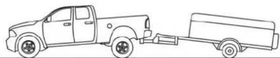
natural_image
Line drawing of a pickup truck and its trailer (no text or symbols)0601115956US
WithoutWeight-DistributingHitch(Incorrect)

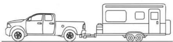
natural_image
Side-view line drawing of a pickup truck and a recreational vehicle (no text or symbols)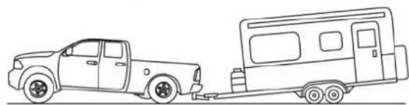
natural_image
Line drawing of a pickup truck pulling a two-wheeled vehicle (no text or symbols)0601115980US
0601115981US
WithWeight-DistributingHitch(Correct)ImproperAdjustmentOfWeight-DistributingHitch
(Incorrect)
RecommendedDistributionHitchAdjustment
- Position the truck to be ready to connect to the trailer (do not connect the trailer).
- Measure the height of the top of the front wheel opening on the fender to ground, this is height H1.
- Attach the trailer to the vehicle without the weight distribution bars connected.
- Measure the height of the top of the front wheel opening on the fender to ground, this is height H2.

-
Install and adjust the tension in the weight distributing bars per the manufacturers' recommendations so that the height of the front fender is approximately (H2-H1)/2+H1 (about 1/2 the difference between H2 and H1 above normal ride height [H1]).
-
Preform a visual inspection of the trailer and weight distributing hitch to confirm manufacturers' recommendations have been met.
| MeasurementExample | Example2500/3500 Height(mm) |
| H1 1030 | |
| H2 1058 | |
| H2-H1 28 | |
| (H2-H1)/2 14 | |
| (H2-H1)/2 + H1 1044 |
NOTE: For all towing conditions, we recommend towing with tow haul mode engaged.
Fifth-WheelHitch
The fifth-wheel hitch is a special high platform with a coupling that mounts over the rear axle of the tow vehicle in the truck bed. It connects a vehicle and fifth-wheel trailer with a coupling king pin.
Your truck may be equipped with a 5th wheel hitch option. Refer to the separately provided 5th wheel hitch safety, care, assembly, and operating instructions.
GooseneckHitch
The gooseneck hitch employs a pivoted coupling arm which attaches to a ball mounted in the bed of a pickup truck. The coupling arm connects to the hitch mounted over the rear axle in the truck bed.
Trailer Hitch Type and Maximum Trailer Weight
The following chart provides the industry standard for the maximum trailer weight a given trailer hitch class can tow and should be used to assist you in selecting the correct trailer hitch for your intended towing condition.
| TrailerHitchClassificationDefinitions | |
| Class | Max.TrailerHitchIndus-tryStandards |
| Class I - Light Duty | 2,000 lbs (907 kg) |
| Class II - Medium Duty | 3,500 lbs (1,587 kg) |
| Class III - Heavy Duty | 5,000 lbs (2,267 kg) |
| Class IV - Extra Heavy Duty | 10,000 lbs (4,535 kg) |
| Fifth Wheel/Gooseneck Greater than 10,000 lbs (4,535 kg) | |
| Refer to the “Trailer Towing Weights (Maximum Trailer Weight Ratings)” for the Maximum Gross Trailer Weight (GTW) towable for your given drivetrain. | |
| All trailer hitches should be professionally installed on your vehicle. | |
Trailer Towing Weights (Maximum Trailer Weight Ratings)
NOTE: For trailer towing information (maximum trailer weight ratings) refer to the following website addresses:
- ramtrucks.com/en/towing_guide/
•ramtruck.ca(Canada)
-rambodybuilder.com
Trailer And Tongue Weight
Never exceed the maximum tongue weight stamped on your bumper or trailer hitch.

text_image
60% 40% 0601085399US WeightDistributionConsider the following items when computing the weight on the rear axle of the vehicle:
• The tongue weight of the trailer.
- The weight of any other type of cargo or equipment put in or on your vehicle.
• The weight of the driver and all passengers.
NOTE: Remember that everything put into or on the trailer adds to the load on your vehicle. Also, additional factory-installed options or dealer-installed options must be considered as part of the total load on your vehicle. Refer to the "Tire And Loading Information" placard for the maximum combined weight of occupants and cargo for your vehicle.
Towing Requirements
To promote proper break-in of your new vehicle drivetrain components, the following guidelines are recommended.
CAUTION!
- Donottowatraileratallduringthefirst500miles (805km)thenewvehicleisdriven.Theengine,axle orotherpartscouldbedamaged.
- Then, during the first 500 miles (805 km) that a trailer istowed, donot drive over 50 mph (80 km/h) and do not make starts at full throttle. This helpsthe engine and other part of the vehicle wear in at the heavier loads.
Perform the maintenance listed in the "Scheduled Servicing". Refer to "Scheduled Servicing" in "Servicing And
Maintenance" for the proper maintenance intervals. When towing a trailer, never exceed the GAWR or GCWR ratings.
WARNING!
Impropertowingcanleadtoacollision.Followthese guidelinestomakeyourtrailertowingassafeas possible:
- Make certain that the load is secured in the trailer and will not shift during travel. When trailering cargothatis not fully secured, dynamic load shifts can occur that may be difficult for the driver to control. You could lose control of your vehicle and have a collision.
- Whenhaulingcargoortowingatrailer, donot overloadyourvehicleortrailer. Overloading can causealossofcontrol, poorperformanceordamage tobrakes, axle, engine, transmission, steering, suspension, chassisstructureortires.
- Safety chains must always be used between your vehicleandtrailer.Alwaysconnectthechainstothe hookretainersofthevehiclehitch.Crossthechains underthetrailertongueandallowenoughslackfor turningcorners.
(Continued)
WARNING!(Continued)
- Vehicleswithtrailersshouldnotbeparkedona grade. Whenparking, applytheparkingbrakeonthe towvehicle. Putthetowvehicletransmissionin PARK. For four-wheeldrivevehicles, makesurethe transfercaseisnotinNEUTRAL. Always, blockor "chock" the trailerwheels.
• GCWRmustnotbeexceeded. - Totalweightmustbedistributedbetweenthetow vehicleandthetrailersuchthatthefollowingfour ratingsarenotexceeded:
1.GVWR
2.GTW
3.GAWR
- Tongueweightratingforthetrailerhitchutilized.
TowingRequirements—Tires
- Do not attempt to tow a trailer while using a compact spare tire.
-
Do not drive more than 50 mph (80 km/h) when towing while using a full size spare tire.
-
Proper tire inflation pressures are essential to the safe and satisfactory operation of your vehicle. Refer to "Tires" in "Servicing And Maintenance" for proper tire inflation procedures.
- Check the trailer tires for proper tire inflation pressures before trailer usage.
- Check for signs of tire wear or visible tire damage before towing a trailer. Refer to "Tires" in "Servicing And Maintenance" for the proper inspection procedure.
- When replacing tires, refer to "Tires" in "Servicing And Maintenance" for the proper tire replacement procedures. Replacing tires with a higher load carrying capacity will not increase the vehicle's GVWR and GAWR limits.
TowingRequirements—TrailerBrakes
- Do not interconnect the hydraulic brake system or vacuum system of your vehicle with that of the trailer. This could cause inadequate braking and possible personal injury.
304 STARTING AND OPERATING
- An electronically actuated trailer brake controller is required when towing a trailer with electronically actuated brakes. When towing a trailer equipped with a hydraulic surge actuated brake system, an electronic brake controller is not required.
- Trailer brakes are recommended for trailers over 1,000 lbs (453 kg) and required for trailers in excess of 2,000 lbs (907 kg).
WARNING!
- Donotconnecttrailerbrakestoyourvehicle'shydraulicbrakelines.Itcanoverloadyourbrakesystemandcauseittofail.Youmightnothavebrakes whenyouneedthemandcouldhaveacollision.
- Towinganytrailerwillincreaseyourstoppingdistance.Whentowingyoushouldallowforadditional spacebetweenyourvehicleandthevehicleinfront ofyou.Failuretodosocouldresultinacollision.
CAUTION!
If the trailer weighsmorethan 1,000 lbs (453 kg) loaded, it should have its own brakes and they should be of adequate capacity. Failure to this could lead to accelerated brakelining wear, higher brake pedal effort, and longer stopping distances.
Integrated Trailer Brake Module—If Equipped
Your vehicle may have an Integrated Trailer Brake Module (ITBM) for Electric and Electric Over Hydraulic (EOH) trailer brakes.
NOTE: This module has been designed and verified with electric trailer brakes and new electric over hydraulic systems. Some previous EOH systems may not be compatible with ITBM.
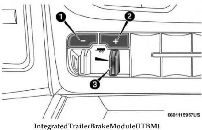
text_image
1 2 - + 3 0601115957US IntegratedTrailerBrakeModule(ITBM)1 — GAIN Adjustment Button
2 — GAIN Adjustment Button
3 — Manual Brake Control Lever
The user interface consists of the following:
ManualBrakeControlLever
Slide the manual brake control lever to the left to activate power to the trailer's electric brakes independent of the tow vehicle's brakes. If the manual brake control lever is activated while the brake is also applied, the greater of the two inputs determines the power sent to the trailer brakes. The trailer and the vehicle's brake lamps will come on when either vehicle braking or manual trailer brakes are applied.
TrailerBrakeStatusIndicatorLight
This light indicates the trailer electrical connection status.
If no electrical connection is detected after the ignition is turned on, pushing the GAIN adjustment button or sliding the manual brake control lever will display the GAIN setting for 10 seconds and the "Trailer Brake Status Indicator Light" will not be displayed.
If a fault is detected in the trailer wiring or the Integrated Trailer Brake Module (ITBM), the "Trailer Brake Status Indicator Light" will flash.
GAINAdjustmentButtons(+/-)
Pushing these buttons will adjust the brake control power output to the trailer brakes in 0.5 increments. The GAIN setting can be increased to a maximum of 10 or decreased to a minimum of 0 (no trailer braking).
GAIN
The GAIN setting is used to set the trailer brake control for the specific towing condition and should be changed as

306 STARTING AND OPERATING
towing conditions change. Changes to towing conditions include trailer load, vehicle load, road conditions and weather.
AdjustingGAIN
NOTE: This should only be performed in a traffic free environment at speeds of approximately 20–25 mph (30–40 km/h).
- Make sure the trailer brakes are in good working condition, functioning normally and properly adjusted. See your trailer dealer if necessary.
- Hook up the trailer and make the electrical connections according to the trailer manufacturer's instructions.
-
When a trailer with electric/EOH brakes is plugged in, the trailer connected message should appear in the instrument cluster display (if the connection is not recognized by the ITBM, braking functions will not be available), the GAIN setting will illuminate and the correct type of trailer must be selected from the instrument cluster display options.
-
Push the UP or DOWN button on the steering wheel until "TRAILER TOW" appears on the screen.
- Push the RIGHT arrow on the steering wheel to enter "TRAILER TOW".
- Push the UP or DOWN buttons until the Trailer Brake Type appears on the screen.
- Push the RIGHT arrow and then push the UP or DOWN buttons until the proper Trailer Brake Type appears on the screen.
- In a traffic-free environment, tow the trailer on a dry, level surface at a speed of 20–25 mph (30–40 km/h) and squeeze the manual brake control lever completely.
- If the trailer wheels lockup (indicated by squealing tires), reduce the GAIN setting; if the trailer wheels turn freely, increase the GAIN setting.
Repeat steps 8 and 9 until the GAIN setting is at a point just below trailer wheel lockup. If towing a heavier trailer, trailer wheel lockup may not be attainable even with the maximum GAIN setting of 10.
| LightElectricHeavyElectricLightEOHHeavyEOH | ||||
| Type of Trailer Brakes | Electric Trailer Brakes | Electric Trailer Brakes | Electric over Hydraulic Trailer Brakes | Electric over Hydraulic Trailer Brakes |
| Load *Under 10,000 lbs | *Above 10,000 lbs *Under | 10,000 lbs *Above 10,000 lbs | 10,000 lbs *Above 10,000 lbs | |
* The suggested selection depends and may change depending on the customer preferences for braking performance. Condition of the trailer brakes, driving and road state may also affect the selection.
DisplayMessages
The trailer brake control interacts with the instrument cluster display. Display messages, along with a single chime, will be displayed when a malfunction is determined in the trailer connection, trailer brake control, or on the trailer. Refer to "Instrument Cluster Display" in "Getting To Know Your Instrument Panel" for further information.
WARNING!
Connectingatrailerthatisnot compatiblewiththe ITBM system may result in reduced or complete loss of trailerbraking. Theremaybeaincreaseinstopping distance or trailer instability which could result in personalinjury.
CAUTION!
Connectingatrailerthatisnot compatiblewiththe ITBM system may result in reduced or complete loss of trailerbraking. Theremaybeincreaseinstopping distance or trailer instability which could result in damagetoyourvehicle,trailer,orotherproperty.
NOTE:
- An aftermarket controller may be available for use with trailers with air or electric-over-hydraulic trailer brake systems. To determine the type of brakes on your trailer and the availability of controllers, check with your trailer manufacturer or dealer.
- Removal of the ITBM will cause errors and it may cause damage to the electrical system and electronic modules of the vehicle. See your authorized dealer if an aftermarket module is to be installed.

308 STARTING AND OPERATING
TowingRequirements—TrailerLightsAndWiring
Whenever you pull a trailer, regardless of the trailer size, stoplights and turn signals on the trailer are required for motoring safety.
The Trailer Tow Package may include a four- and seven-pin wiring harness. Use a factory approved trailer harness and connector.
NOTE: Do not cut or splice wiring into the vehicle's wiring harness.
The electrical connections are all complete to the vehicle but you must mate the harness to a trailer connector. Refer to the following illustrations.
NOTE:
- Disconnect trailer wiring connector from the vehicle before launching a boat (or any other device plugged into vehicle's electrical connect) into water.
- Be sure to reconnect after clear from water area.
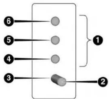
flowchart
graph TD
    A["6"] --> B[" "]
    C["5"] --> D[" "]
    E["4"] --> F[" "]
    G["3"] --> H[" "]
    I[" "] --> J["1"]
    K["2"] --> L["2"]
0601085400US
Four-PinConnector
1 — Female Pins 4 — Park
2 — Male Pin 5 — Left Stop/Turn
3 — Ground 6 — Right Stop/Turn
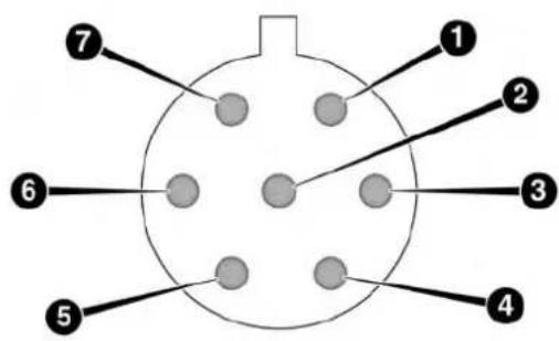
text_image
1 2 3 4 5 6 70601085401US
Seven-PinConnector
1 — Battery 5 — Ground
2 — Backup Lamps
3 — Right Stop/Turn
4 — Electric Brakes
6 — Left Stop/Turn
7 — Running Lamps
Towing Tips
Before setting out on a trip, practice turning, stopping, and backing up the trailer in an area located away from heavy traffic.
AutomaticTransmission
The DRIVE range can be selected when towing. The transmission controls include a drive strategy to avoid frequent shifting when towing. However, if frequent shifting does occur while in DRIVE, select TOW/HAUL mode or select a lower gear range (using the Electronic Range Select (ERS) shift control).
NOTE: Using TOW/HAUL mode or selecting a lower gear range (using the ERS shift control) while operating the vehicle under heavy loading conditions will improve performance and extend transmission life by reducing excessive shifting and heat build up. This action will also provide better engine braking.
When towing a loaded trailer up steep grades at low speeds (20 mph [32 km/h] or below), holding your vehicle in first gear (using the ERS shift control) can help to avoid transmission overheating.
If you regularly tow a trailer for more than 45 minutes of continuous operation, then change the automatic transmission fluid and filter(s) as specified for "police, taxi, fleet, or frequent trailer towing." Refer to the "Maintenance Plan" for the proper maintenance intervals.

310 STARTING AND OPERATING
NOTE: Check the automatic transmission fluid level before towing.
Tow/HaulMode
To reduce potential for automatic transmission overheating, activate TOW/HAUL mode when driving in hilly areas, or select a lower gear range (using the Electronic Range Select (ERS) shift control) on more severe grades.
SpeedControl—IfEquipped
- Do not use on hilly terrain or with heavy loads.
- When using the speed control, if you experience speed drops greater than 10 mph (16 km/h), disengage until you can get back to cruising speed.
- Use speed control in flat terrain and with light loads to maximize fuel efficiency.
CoolingSystem
To reduce potential for engine and transmission overheating, take the following actions:
CityDriving
- In city traffic — while stopped, place the transmission in NEUTRAL, but do not increase engine idle speed.
HighwayDriving
- Reduce speed.
• Temporarily turn off air conditioning.
AirSuspensionSystem
To aid in attaching/detaching the trailer from the vehicle, the air suspension system can be used. Refer to "Air Suspension System" in "Starting And Operating" for further information.
NOTE: The vehicle must remain in the engine running position while attaching a trailer for proper leveling of the air suspension system.
SNOWPLOW
2500/3500 Models Only
Snowplow Prep Packages are available as a factory installed option. These packages include components necessary to equip your vehicle with a snowplow.

NOTE: Before installation of a snowplow it is highly recommended that the owner/installer obtain and follow the recommendations contained within the current Body Builders Guide. See your authorized dealer, installer or snowplow manufacturer for this information. There are unique electrical systems that must be connected to properly assure operator safety and prevent overloading vehicle systems.
WARNING!
Attachingasnowplowtothisvehiclecouldadversely affectperformanceoftheairbagsysteminacollision. Donotexpectthattheairbagwillperformasdescribed earlierinthismanual.
CAUTION!
The "LampOut" indicator could illuminate if exterior lamps are not properly installed.
BeforePlowing
- Check the hydraulic system for leaks and proper fluid level.
-
Check the mounting bolts and nuts for proper tightness.
-
Check the runners and cutting edge for excessive wear. The cutting edge should be 14 to 12 in (6 cm to 1.2 cm) above ground in snow plowing position.
- Check that snowplow lighting is connected and functioning properly.
SnowplowPrepPackageModelAvailability
ForInformationaboutsnowplowapplicationsvisit www.ramtrucks.comorrefertothecurrentBodyBuilders Guide.
- The maximum number of occupants in the truck should not exceed two.
- The total GVWR or the Front GAWR or the Rear GAWR should never be exceeded.
- Cargo capacity will be reduced by the addition of options or passengers, etc.
The loaded vehicle weight, including the snowplow system, all aftermarket accessories, driver, passengers, options, and cargo, must not exceed either the Gross Vehicle Weight (GVWR) or Gross Axle Weight (GAWR) ratings. These weights are specified on the Safety Compliance Certification Label on the driver's side door opening.

312 STARTING AND OPERATING
NOTE: Detach the snowplow when transporting passengers.
Vehicle front end wheel alignment was set to specifications at the factory without consideration for the weight of the plow. Front end toe-in should be checked and reset if necessary at the beginning and end of the snowplow season. This will help prevent uneven tire wear.
The blade should be lowered whenever the vehicle is parked.
Maintain and operate your vehicle and snowplow equipment following the recommendations provided by the specific snowplow manufacturer.
OverTheRoadOperationWithSnowplowAttached
The blade restricts air flow to the radiator and causes the engine to operate at higher than normal temperatures. Therefore, when transporting the plow, angle the blade completely and position it as low as road or surface conditions permit. Do not exceed 40 mph (64 km/h). The operator should always maintain a safe stopping distance and allow adequate passing clearance.
OperatingTips
Under ideal snow plowing conditions, 20 mph (32 km/h) should be maximum operating speed. The operator should be familiar with the area and surface to be cleaned. Reduce speed and use extreme caution when plowing unfamiliar areas or under poor visibility.
GeneralMaintenance
Snowplows should be maintained in accordance with the plow manufacturer's instructions.
Keep all snowplow electrical connections and battery terminals clean and free of corrosion.
When plowing snow, to avoid transmission and drivetrain damage, the following precautions should be observed.
- Operate with transfer case in 4LO when plowing small or congested areas where speeds are not likely to exceed 15mph (24km / h) . At higher speeds operate in 4HI.
- Vehicles with automatic transmissions should use 4LO range when plowing deep or heavy snow for extended periods of time to avoid transmission overheating.
- Do not shift the transmission unless the engine has returned to idle and wheels have stopped. Make a practice of stepping on the brake pedal while shifting the transmission.

RECREATIONAL TOWING (BEHIND MOTORHOME, ETC.)
Towing This Vehicle Behind Another Vehicle
| TowingConditionWheelsOFFTheGround | Two-WheelDriveModels | Four-WheelDriveModels | |
| Flat Tow NONE | TOTAL- | LOWED | SeeInstructionsAutomatic transmission in PARKManual transmission in gear (NOT in NEU-TRAL)Transfer case in NEUTRAL (N)Tow in forward direction |
| Dolly Tow Front | TOTAL- | LOWED | NOTALLOWED |
| Rear OK NOTALLOWED | |||
| On Trailer ALL OK | OK | ||
NOTE:
- When towing your vehicle, always follow applicable state and provincial laws. Contact state and provincial Highway Safety offices for additional details.
314 STARTING AND OPERATING
Recreational Towing — Two-Wheel Drive Models
DONOTflattowthisvehicle.Damagethedrivetrain willresult.
Recreational towing (for two-wheel drive models) is allowed ONLY if the rear wheels are OFF the ground. This may be accomplished using a tow dolly or vehicle trailer. If using a tow dolly, follow this procedure:
- Properly secure the dolly to the tow vehicle, following the dolly manufacturer's instructions.
- Drive the rear wheels onto the tow dolly.
- Firmly apply the parking brake. Place automatic transmission in PARK, manual transmission in gear (not in NEUTRAL).
- Properly secure the rear wheels to the dolly, following the dolly manufacturer's instructions.
- Turn the ignition OFF and remove the key fob.
- Install a suitable clamping device, designed for towing, to secure the front wheels in the straight position.
CAUTION!
- Towingwiththerearwheelsonthegroundwill causeseveretransmissiondamage.Damagefrom impropertowingisnotcoveredundertheNew VehicleLimitedWarranty.
- Donotdisconnectthedriveshaftbecausefluidmay leakfromthetransmission,causingdamagetointernalparts.
Recreational Towing — Four-Wheel Drive Models
NOTE: Both the manual shift and electronic shift transfer cases must be shifted into NEUTRAL (N) for recreational towing. Automatic transmissions must be shifted into PARK for recreational towing. Manual transmissions must be placed in gear (NOT in NEUTRAL) for recreational towing. Refer to the following for the proper transfer case NEUTRAL (N) shifting procedure for your vehicle.
CAUTION!
- DONOTdollytowany4WDvehicle.Towingwith onlyonesetofwheelsontheground(frontorrear) will cause severe transmission and/or transfer case
CAUTION!(Continued)
damage.TowwithallfourwheelseitherONthe ground,orOFFtheground(usingavehicletrailer).
- Towonlyintheforwarddirection.Towingthis vehiclebackwardscancauseseveredamagetothe transfercase.
- Before recreational towing, the transfer case must be in NEUTRAL. Tobecertain the transfer case is fully in NEUTRAL, perform the procedure outlined under "Shifting Into NEUTRAL". Internal transmission damage will result, if the transfer case is not in NEUTRAL during towing.
- AutomatictransmissionsmustbeplacedinPARK, andmanualtransmissionsmustbeplacedingear (notinNeutral)forrecreationaltowing.
- Towing this vehicle inviolation of the aboverequirements can cause severetransmission and/or transfer casedamage. Damage from impropertowing is not covered under the New Vehicle Limited Warranty.
- Donotdisconnectthereardriveshaftbecausefluid willleakfromthetransfercase,causingdamageto internalparts.
- Donotuseabumper-mountedclamp-ontowbaron yourvehicle.Thebumperfacebarwillbedam
ShiftingIntoNEUTRAL(N)
Use the following procedure to prepare your vehicle for recreational towing.
WARNING!
Youorotherscouldbeinjuredorkilledifyouleavethe vehicleunattendedwiththetransfercaseintheNEUTRAL(N)positionwithoutfirstfullyengagingthe parkingbrake. ThetransfercaseNEUTRAL(N)positiondisengagesboththefrontandreadriveshafts fromthepowertrain, andwillallowthevehicletoroll, eveniftheautomatictransmissionisinPARK(or manualtransmissionisingear). Theparkingbrake shouldalwaysbeappliedwhenthedriverisnotinthe vehicle.
CAUTION!
It isnecessary to follow these stepstobecertain that the transfer case is fully in NEUTRAL (N) before recreational towing top prevent damaget internal parts.
316 STARTING AND OPERATING
- Bring the vehicle to a complete stop on level ground, with the engine running. Firmly apply the parking brake.
- Shift the transmission to NEUTRAL.
- Press and hold the brake pedal.
- Depress the clutch pedal on a manual transmission.
- Shift the transfer case into NEUTRAL:
- With manual shift transfer case, shift the transfer case lever into NEUTRAL (N).
- With electronic shift transfer case, push and hold the transfer case NEUTRAL (N) button. Some models have a small, recessed "N" button (at the center of the transfer case switches) that must be pressed using a ballpoint pen or similar object. Other models have a rectangular NEUTRAL switch, below the rotary transfer case control knob. The NEUTRAL (N) indicator light will blink while the shift is in progress. The light will stop blinking (stay on solid) when the shift to NEUTRAL (N) is complete. After the shift is completed and the NEUTRAL (N) light stays on, release the NEUTRAL (N) button.
-
Release the parking brake.
-
Shift the transmission into REVERSE.
- Release the brake pedal (and clutch pedal on manual transmissions) for five seconds and ensure that there is no vehicle movement.
- Repeat steps seven and eight with automatic transmission in DRIVE or manual transmission in first gear.
- Shift the transmission to NEUTRAL. Firmly apply the parking brake. Turn OFF the engine. For vehicles with Keyless Enter-N-Go, push and hold the ENGINE START/STOP button until the engine shuts off.
- Shift the transmission into PARK or place manual transmission in gear (NOT in NEUTRAL).
- Place the ignition in the OFF mode, and remove the key fob.
- Attach the vehicle to the tow vehicle using a suitable tow bar.
- Release the parking brake.
NOTE: With electronic shift transfer case:
- Steps 2 through 4 are requirements that must be met before pushing the NEUTRAL (N) button, and must continue to be met until the shift has been completed. If

any of these requirements are not met before pushing the NEUTRAL (N) button or are no longer met during the shift, the NEUTRAL (N) indicator light will flash continuously until all requirements are met or until the NEUTRAL (N) button is released.
- The ignition must be in the ON/RUN mode for a shift to take place and for the position indicator lights to be operable. If the ignition is not in the ON/RUN mode, the shift will not take place and no position indicator lights will be on or flashing.
- A flashing NEUTRAL (N) position indicator light indicates that shift requirements have not been met.
ShiftingOutOfNEUTRAL(N)
Use the following procedure to prepare your vehicle for normal usage:
- Bring the vehicle to a complete stop, leaving it connected to the tow vehicle.
- Firmly apply the parking brake.
- Turn the ignition to the ON/RUN mode, but do not start the engine.
-
Press and hold the brake pedal.
-
Shift the transmission into NEUTRAL.
-
With manual shift transfer case, shift the transfer case lever to the desired position.
- With electronic shift transfer case with rotary selector switch, push and hold the transfer case NEUTRAL (N) button until the NEUTRAL (N) indicator light turns off. After the NEUTRAL (N) indicator light turns off, release the NEUTRAL (N) button. After the NEUTRAL (N) button has been released, the transfer case will shift to the position indicated by the selector switch.
- With electronic shift transfer case with push-button selector switch, push and hold the switch for the desired transfer case position, until the NEUTRAL (N) indicator light turns off and the desired position indicator light turns on.
NOTE: When shifting out of transfer case NEUTRAL (N), the engine should remain OFF to avoid gear clash.
- Shift automatic transmission into PARK.
- Release the brake pedal (and clutch pedal on a manual transmission).
- Disconnect vehicle from the tow vehicle.
318 STARTING AND OPERATING
-
Start the engine.
-
Press and hold the brake pedal.
-
Release the parking brake.
-
Shift the transmission into gear, release the brake pedal (and clutch pedal on manual transmissions), and check that the vehicle operates normally.
NOTE: With electronic shift transfer case:
- Steps 3 and 4 are requirements that must be met before pushing the button to shift out of NEUTRAL (N), and must continue to be met until the shift has been completed. If any of these requirements are not met before pushing the button or are no longer met during the shift, the NEUTRAL (N) indicator light will flash continuously until all requirements are met or until the button is released.
- The ignition must be in the ON/RUN mode for a shift to take place and for the position indicator lights to be operable. If the ignition is not in the ON/RUN mode, the shift will not take place and no position indicator lights will be on or flashing.
- A flashing NEUTRAL (N) position indicator light indicates that shift requirements have not been met
DRIVING TIPS
Driving On Slippery Surfaces
Acceleration
Rapid acceleration on snow covered, wet, or other slippery surfaces may cause the driving wheels to pull erratically to the right or left. This phenomenon occurs when there is a difference in the surface traction under the rear (driving) wheels.
WARNING!
Rapidaccelerationonslipperysurfacesidangerous. Unequaltractioncancausesuddenpullingoftherear wheels.Youcouldlosecontrolofthevehicleand possiblyhaveacollision.Accelerateslowlyandcarefullywheneverthereislikelytobepoortraction(ice, snow,wet,mud,loosesand,etc.).
Driving Through Water
Driving through water more than a few inches/centimeters deep will require extra caution to ensure safety and prevent damage to your vehicle.

Flowing/RisingWater
WARNING!
Donotdriveonoracrossaroadorpathwherewateris flowingand/orrising(asinstormrun-off).Flowing watercanwearawaytheroadorpath'ssurface and causeyourvehicletosinkintodeeperwater.Furthermore,flowingand/orrisingwatercancarryyourvehicleawaysswiftly.Failureretofollowthiswarningmay resultininjuriesthatareseriousorfataltoyou,your passengers,andothersaroundyou.
ShallowStandingWater
Although your vehicle is capable of driving through shallow standing water, consider the following Cautions and Warnings before doing so.
WARNING!
- Drivingthroughstandingwaterlimitsyourvehicle's tractioncapabilities.Donotexceed5mph(8km/h) whendrivingthroughstandingwater.
- Drivingthroughstandingwaterlimitsyourvehicle's brakingcapabilities,whichincreasesstoppingdistances.Therefore,afterdrivingthroughstanding water,driveslowlyandlightlypressonthebrake pedalseveraltimestodrythebrakes.
- Failuretofollowthesewarningsmayresultininjuriesthatareseriousorfataltoyou,yourpassengers, andothersaroundyou.
CAUTION!
- Alwayscheckthedepthofthestandingwaterbefore drivingthroughit.Neverdrivethroughstanding waterthatisdeeperthanthebottomofthetirerims mountedonthevehicle.
- Determinetheconditionoftheroadorthepaththat isunderwaterandifthereareanyobstaclesinthe waybeforedrivingthroughthestandingwater.
- Donotexceed5mph(8km/h)whendrivingthrough standingwater. Thiswillminimizewaveeffects.
- Drivingthroughstandingwatermaycausedamage toyourvehicle'sdrivetraincomponents.Alwaysinspectyourvehicle'sfluids(i.e.,engineoil,transmission,axle,etc.)forsignsofcontamination(i.e.,fluid thatismilkyorfoamyinappearance)afterdriving throughstandingwater.Donotcontinuetooperate thevehicleifanyfluidappearscontaminated,asthis mayresultinfurtherdamage.Suchdamageisnot coveredbytheNewVehicleLimitedWarranty.
- Gettingwaterinsideyourvehicle'senginecancause ittolockupandstallout,andcauseseriousinternal damagetotheengine.Suchdamageisnotcoveredby theNewVehicleLimitedWarranty.
IN CASE OF EMERGENCY
CONTENTS
■HAZARD WARNING FLASHERS....322
■ASSIST AND SOS MIRROR — IF EQUIPPED . . .322
■BULB REPLACEMENT....327
□Replacement Bulbs....327
□Replacing Exterior Bulbs....328
■FUSES....333
□Power Distribution Center . . . . . . . . . . . . . . . . . . . . . . 334
■JACKING AND TIRE CHANGING....341
□4500/5500 Models....341
□Preparations For Jacking....341
□Jacking Instructions 4500 And 5500 Series. . . . . .342
□To Stow The Flat Or Spare — If Equipped . . . . .346
□Hub Caps/Wheel Covers — If Equipped . . . . . .346
■JUMP STARTING....347
□Preparations For Jump Start .....348
□Jump Starting Procedure....349
■IF YOUR ENGINE OVERHEATS....350
■GEAR SELECTOR OVERRIDE .....351
■FREEING A STUCK VEHICLE .....352
■TOWING A DISABLED VEHICLE .....354
□Two-Wheel Drive Models....355
□Four-Wheel Drive Models .....356
□Emergency Tow Hooks — If Equipped. . . . . . . .356
■ENHANCED ACCIDENT RESPONSE SYSTEM (EARS)....357
■EVENT DATA RECORDER (EDR) .....357
HAZARD WARNING FLASHERS
The Hazard Warning flasher switch is located on the upper switch bank just below the radio.

Push the switch to turn on the Hazard Warning
flasher. When the switch is activated, all directional turn signals will flash on and off to warn oncoming traffic of an emergency. Push the switch a second time to turn off the Hazard Warning flashers.
This is an emergency warning system and it should not be used when the vehicle is in motion. Use it when your vehicle is disabled and it is creating a safety hazard for other motorists.
When you must leave the vehicle to seek assistance, the Hazard Warning flashers will continue to operate even though the ignition is placed in the OFF position.
NOTE: With extended use the Hazard Warning flashers may wear down your battery.
ASSIST AND SOS MIRROR — IF EQUIPPED
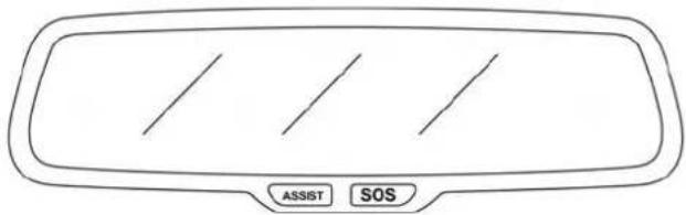
natural_image
Front view of a car dashboard with three horizontal lines and two labeled buttons (ASSIST and SOS) at the bottom (no text or symbols on the dashboard itself)0306114048US
AssistAndSOSMirror
If equipped, the rearview mirror contains an ASSIST and a SOS button.
WARNING!
ALWAYSobeytrafficlawsandpayattentiontothe road.ALWAYSdrivesafelywithyourhandsonthe steeringwheel.YouhavefullresponsibilityandassumeallrisksrelatedtotheuseoftheUconnectand

(Continued)
WARNING!(Continued)
SiriusXMGuardianfeaturesandapplicationsinthis vehicle.OnlyuseUconnectfeaturesandSiriusXM Guardianserviceswhenitissafetodoso.Failureuretodo somayresultinanaccidentinvolvingseriousinjuryor death.
NOTE:
- Your vehicle may be transmitting data as authorized by the subscriber.
- The SOS and ASSIST buttons will only function if you are connected to an operable LTE (voice/data) or 4G (data) network. Other Uconnect services will only be operable if your SiriusXM Guardian service is active and you are connected to an operable LTE (voice/data) or 4G (data) network.
ASSISTCall
The ASSIST Button is used to automatically connect you to any one of the following support centers:
- Roadside Assistance – If you get a flat tire, or need a tow, just push the ASSIST button and you'll be connected to
someone who can help. Roadside Assistance will know what vehicle you're driving and its location. Additional fees may apply for roadside Assistance.
- SiriusXM Guardian Customer Care – In-vehicle support for SiriusXM Guardian.
- Vehicle Customer Care – Total support for all other vehicle issues.
SOSCall
- Push the SOS Call button on the Rearview Mirror.
NOTE: In case the SOS Call button is pushed in error, there will be a ten second delay before the SOS Call system initiates a call to a SOS operator. To cancel the SOS Call connection, push the SOS call button on the Rearview Mirror or press the cancellation button on the Device Screen. Termination of the SOS Call will turn off the green LED light on the Rearview Mirror.
- The LED light located between the ASSIST and SOS buttons on the Rearview Mirror will turn green once a connection to a SOS operator has been made.
324 IN CASE OF EMERGENCY
-
Once a connection between the vehicle and a SOS operator is made, the SOS Call system may transmit the following important vehicle information to a SOS operator:
-
Indication that the occupant placed a SOS Call.
• The vehicle brand. -
The last known GPS coordinates of the vehicle.
-
You should be able to speak with the SOS operator through the vehicle audio system to determine if additional help is needed.
WARNING!
ALWAYSobeytrafficlawsandpayattentiontothe road.ALWAYSdrivesafelywithyourhandsonthe steeringwheel.YouhavefullresponsibilityandassumeallrisksrelatedtotheuseoftheUconnectandSiriusXMGuardianfeaturesandapplicationsinthis vehicle.OnlyuseUconnectfeaturesandSiriusXM Guardianserviceswhenitissafetodoso.Failureretodo somayresultinanaccidentinvolvingseriousinjuryor death.
NOTE:
- Your vehicle may be transmitting data as authorized by the subscriber.
-
Once a connection is made between the vehicle's SOS Call system and the SOS operator, the SOS operator may be able to open a voice connection with the vehicle to determine if additional help is needed. Once the SOS operator opens a voice connection with the vehicle's SOS Call system, the operator should be able to speak with you or other vehicle occupants and hear sounds occurring in the vehicle. The vehicle's SOS Call system will attempt to remain connected with the SOS operator until the SOS operator terminates the connection.
-
The SOS operator may attempt to contact appropriate emergency responders and provide them with important vehicle information and GPS coordinates.
WARNING!
- If anyone in the vehicle could be in danger (e.g., fire or smoke is visible, dangerous road conditions or location), donot wait for voice contact from
WARNING!(Continued)
EmergencyServicesAgent.Alloccupantsshouldexit thevehicleimmediatelyandmovetoasafelocation.
- Neverplaceanythingonornearthevehicle'soperablenetworkandGPSantennas.Youcouldprevent operablenetworkandGPSsignalreception,which canpreventyourvehiclefromplacinganemergency call.AnoperablenetworkandGPSsignalreception isrequiredfortheSOSCallsystemtofunction properly.
- TheSOSCallsystemisembeddedintothevehicle's electricalsystem.Donotaddaftermarketelectrical equipmenttothevehicle'selectricalsystem.Thismay preventyourvehiclefromsendingasignaltoinitiate anemergencycall.Toavoidinterferencethatcancause theSOSCallsystemtofail,neveraddaftermarket equipment(e.g.,two-waymobileradio,CBradio,data recorder,etc.)toyourvehicle'selectricalsystemor modifytheantennasonryourvehicle.IFYOURVE-HICLELOSESBATTERYPOWERFORANYREA-SON(INCLUDINGDURINGOR AFTERANACCIDENT),THEUCONNECTFEATURES,APPSAND SERVICES,AMONGOTHERS,WILLNOTOPER-ATE.
WARNING!(Continued)
- ModificationstoanypartoftheSOSCallsystem couldcausetheairbagsystemtofailwhenyouneed it.Youcouldbeinjurediftheairbagsystemisnot theretohelpprotectyou.
SOSCallSystemLimitations
Vehicles sold in Mexico DONOThave SOS Call system capabilities.
SOS or other emergency line operators in Mexico may not answer or respond to SOS system calls.
If the SOS Call system detects a malfunction, any of the following may occur at the time the malfunction is detected, and at the beginning of each ignition cycle:
- The Rearview Mirror light located between the ASSIST and SOS buttons will continuously be illuminated red.
- The Device Screen will display the following message "Vehicle device requires service. Please contact your dealer."
- An In-Vehicle Audio message will state "Vehicle device requires service. Please contact your dealer."
WARNING!
- IgnoringtheRearviewMirrorlightcouldmeanyou willnothaveSOSCallservices.IftheRearview Mirrorlightisilluminated,haveanaauthorized dealerservicetheSOSCallsystemimmediately.
- TheOccupantRestraintControlmoduleturnsonthe airbagWarningLightontheinstrumentpanelifa malfunctioninanypartofthesystemisdetected.If theAirBagWarningLightisilluminated,havean authorizeddealerservicetheOccupantRestraint Controlsystemimmediately.
Even if the SOS Call system is fully functional, factors beyond FCA US LLC's control may prevent or stop the SOS Call system operation. These include, but are not limited to, the following factors:
- Delayed accessories mode is active.
• The ignition is in the OFF position. - The vehicle's electrical systems are not intact.
- The SOS Call system software and/or hardware are damaged during a crash.
- The vehicle battery loses power or becomes nected during a vehicle crash.
- LTE (voice/data) or 4G (data) network and/or Global Positioning Satellite signals are unavailable or obstructed.
• Equipment malfunction at the SOS operator facility. - Operator error by the SOS operator.
- LTE (voice/data) or 4G (data) network congestion.
- Weather.
• Buildings, structures, geographic terrain, or tunnels.
WARNING!
ALWAYSobeytrafficlawsandpayattentiontothe road.ALWAYSdrivesafely with yourhandsonthe steering wheel. You have full responsibility and assumeallrisksrelatedtotheuseoftheUconnectand SiriusXMGuardianfeaturesandapplicationsinthis vehicle.OnlyuseUconnectfeaturesandSiriusXM Guardianserviceswhenitissafetodoso.Failureretodo somayresultinanaccidentinvolvingseriousinjuryor death.
NOTE:
- Your vehicle may be transmitting data as authorized by the subscriber.
- Never place anything on or near the vehicle's LTE (voice/data) or 4G (data) and GPS antennas. You could prevent LTE (voice/data) or 4G (data) and GPS signal reception, which can prevent your vehicle from placing an emergency call. An operable LTE (voice/data) or 4G (data) network connection and a GPS signal is required for the SOS Call system to function properly.
GeneralInformation
This device complies with Part 15 of the FCC Rules. Operation is subject to the following two conditions: (1) This device may not cause harmful interference, and (2) this device must accept any interference received, including interference that may cause undesired operation.
NOTE: Changes or modifications not expressly approved by the party responsible for compliance could void the user's authority to operate the equipment.
| CAUTION! |
| Toavoiddamagethemirrorduringcleaning,never sprayanycleaningsolutiondirectlyontothemirror.Applythesolutionontoacleanclothandwipethe mirrorclean. |
BULB REPLACEMENT
Replacement Bulbs
LIGHT BULBS — Interior
| BulbNumber | |
| Overhead Console Lamps TS 212-2 | |
| Dome Lamp 7679 | |
| For lighted switches, see your authorized dealer for replacement instructions. | |
LIGHT BULBS — Exterior
| BulbNumber | |
| Quad Headlamp – Low Beam | H11 |
| Quad Headlamp – High Beam | 9005 |
| Quad Headlamp – Front Turn Signal Lamp | 3157NA |
| Premium Headlamp – Low Beam | HIR2 |
| Premium Headlamp – High Beam | 9005 |
| Premium Headlamp – Front Turn Signal Lamp | LED (See authorized dealer for service) |
| Horizontal Fog Lamp 914$ | |
| Vertical Fog Lamp 9006 | |
| Cab Roof Marker Lamps 194NA | |
| Center High Mounted Stop Lamp | 921 |
| BulbNumber | |
| Rear Cargo Lamp 921 | |
| Box Off Tail Lamps – Stop/Turn/Tail/License Plate | 1157 |
| Box Off Tail Lamps – Back Up | 1156 |
Replacing Exterior Bulbs
BaseQuad/PremiumBi-Halogen:LowBeam Headlamp, HighBeamHeadlamp, FrontParkAnd Turn—IfEquipped
- Open the hood.
- Disconnect and isolate the negative battery cable.
- Remove the six plastic push-in fasteners that secure the upper radiator seal to the grille support and both fender ledges.
- Remove the two plastic push-in rivets that secure the upper radiator seal to the radiator.
-
Remove the upper radiator seal from the vehicle.
-
Remove the two headlamp assembly attachment screws.

natural_image
Mechanical assembly diagram showing a valve mechanism with two arrows indicating direction (no text or symbols present)HeadlampAssemblyAttachmentScrewLocations
-
Reach into the front wheel house ahead of the front wheel, remove the fastener, and lift the cover over the access hole in the front of the wheel house splash shield. Access to the rear of the lamp can be gained through this access hole.
-
Reach through the access hole of the wheel house splash shield and lift the slide lock upward far enough to disengage it from the lock post on the back of the front lamp unit housing.

natural_image
Diagram of a car seatbelt buckle assembly showing left side and right side views (no text or labels)0801116012US
SlideLock
-
Remove the headlamp assembly. Grasp the outboard edge of the lamp and pull it straight forward to disengage the ball stud from the plastic grommet.
-
Disconnect the wiring harness connectors from the bulb socket.
-
Replace bulb(s) as necessary.

CAUTION!
- Donotcontaminate the bulb glass by touching it with your fingers or by allowing it to contact other oilysurfaces. Shortened bulblifewill result.
- Alwaysusethecorrectbulbsizeandtypeforreplacement.Anincorrectbulbsizeortypemayoverheat andcausedamagethelamp,thebulbsocket,orthe lampwiring.
NOTE: There are access covers over both headlamp bulb access holes in the quad front lamp unit housing (if equipped). These covers MUST be reinstalled after the bulb has been replaced.
FogLamps—IfEquipped
- Reach under and behind the front bumper to access the back of the front fog lamp housing.
- Disconnect the fog lamp wiring harness connector from the fog lamp bulb.
-
Rotate the bulb counterclockwise 14 turn to unlock the bulb from the housing.
-
Pull the bulb straight out from the housing.
CAUTION!
Donotcontaminatethebulbglassbytouchingitwith yourfingersorbyallowingittocontactotheroily surfaces.Shortenedbulblifewillresult.
CenterHigh-MountedStoplamp(CHMSL)With CargoLamp
- Remove the two screws holding the housing/lens to the body as shown.
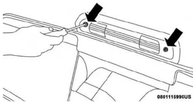
natural_image
Line drawing of a hand using a tool to adjust or install a car interior panel (no text or symbols visible)CHMSLMountingScrewLocations
- Separate the connector holding the housing and wiring harness to the body.
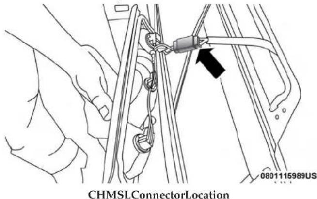
text_image
CHMSLConnectorLocation 0801115989US-
Turn the desired bulb socket 14 turn and remove the socket and bulb from housing.
-
Pull the desired bulb straight from the socket.
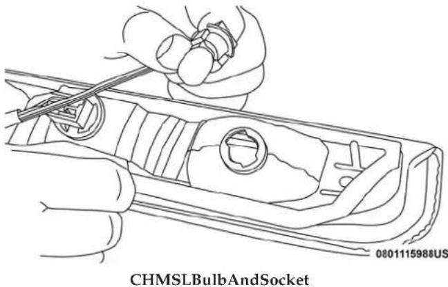
text_image
0801115988US CHMSLBulbAndSocketCAUTION!
Donotcontaminatethebulbglassbytouchingitwith yourfingersorbyallowingittocontactotheroily surfaces.Shortenedbulblifewillresult.
• Outside Bulbs: Cargo Lamps
• Inside Bulb: Center High-Mounted Stop Lamp
- Reverse the procedure for installation of bulbs and housing.

332 IN CASE OF EMERGENCY
CabTopClearanceLamps—IfEquipped
- Remove the two screws from the top of the lamp.
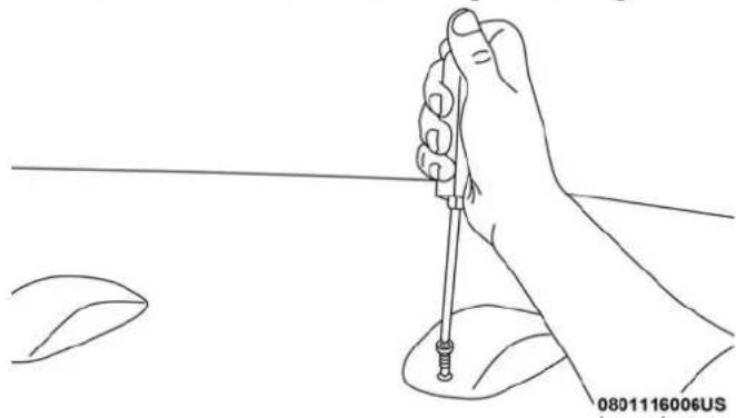
natural_image
Line drawing of a hand holding a screwdriver with a pointed tip, against a plain background (no text or symbols)RemovingRearScrewFromClearanceLamp
- Rotate the bulb socket 14 turn and pull it from the lamp assembly.
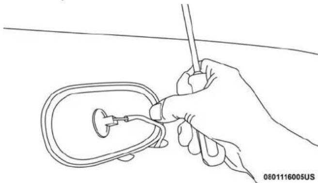
natural_image
Line drawing of a hand holding a medical or surgical tool near a device (no text or symbols visible)RemovingBulbSocketFromClearanceLamp
- Pull the bulb straight from it's socket and replace.
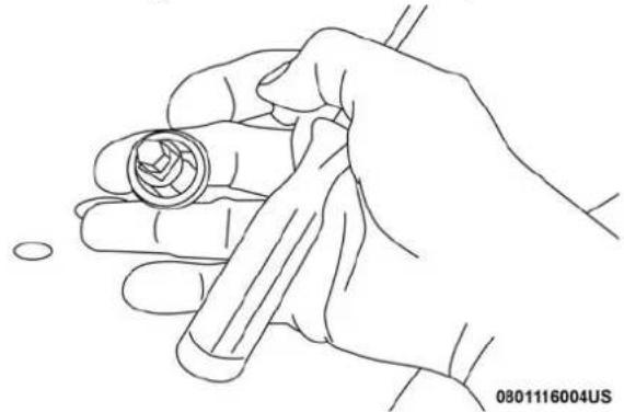
natural_image
Line drawing of a hand holding a cylindrical object with a ring, no text or symbols presentRemovingTheBulbFromTheBulbSocket
IN CASE OF EMERGENCY 333
FUSES
WARNING!
- Whenreplacingablownfuse,alwaysuseanappropriatereplacementfusewiththesameampratingas theoriginalfuse.Neverreplaceafusewithanother fuseofhigheramprating.Neverreplaceablown fusewithmetalwiresoranyothermaterial.Donot placeafuseinsideacircuitbreakercavityorvice versa.Failureretouseproperfusesmayresultin seriouspersonalinjury,fireand/orpropertydamage.
- Before-replacingafuse, makesurethattheignitionis offandthatalltheotherservicesareswitchedoff and/ordisengaged.
- Ifthereplacedfuseblowsagain,contactanauthorizeddealer.
- Ifageneralprotectionfuseforsafetysystems(air bagsystem,brakingsystem),powerunitsystems (enginesystem,transmissionsystem)orsteering systemblows,contactanauthorizeddealer.
Power Distribution Center
The Power Distribution Center is located in the engine compartment near the battery. This center contains cartridge fuses, micro fuses, relays, and circuit breakers. A description of each fuse and component may be stamped on the inside cover, otherwise the cavity number of each fuse is stamped on the inside cover that corresponds to the following chart.

natural_image
Illustration of a mechanical device with a black arrow pointing to a component, no text or symbols present.PowerDistributionCenterLocation
| CavityCartridgeFuseMicroFuseDescription | |||
| F01 80 Amp Black – Rad Fan Control Module – If Equipped | |||
| F03 | 60 Amp Yellow – | Rad Fan – If Equipped | |
| F05 | 40 Amp Green | – | Compressor for Air Suspension – If Equipped |
| F06 | 40 Amp Green | – | Antilock Brakes/Electronic Stability Control Pump |
| F07 | 40 Amp Green | – | Starter Solenoid |
| CavityCartridge | FuseMicroFuseDescription | ||
| F08 20 Amp Blue (1500 LD/Cummins Diesel) | - Emissions | Diesel - If Equipped | |
| F09 40 Amp Green (Special Services Vehicle & Cummins Diesel) | - Diesel Fuel | Heater - If Equipped | |
| F10 40 Amp Green - Body Controller / Exterior Lighting #2 | |||
| F10 50 Amp Red - Body Controller / Exterior Lighting #2 - If | Equipped with Stop/Start | ||
| F11 | 30 Amp Pink | - | Integrated Trailer Brake Module - If Equipped |
| F12 40 Amp Green - Body Controller #3 / Power Locks | |||
| F13 40 Amp Green - Blower Motor | |||
| F14 40 Amp Green - Body Controller #4 / Interior Lighting | |||
| F16 | 30 Amp Pink | - | Smart Bar - If Equipped |
| F19 20 Amp Blue (1500 LD Diesel)30 Amp Pink (Cummins Diesel) | - | SCR - If Equipped | |
| F20 | 30 Amp Pink | - | Passenger Door Module |
| F21 | 30 Amp Pink | - | Drive Train Control Module |
| F22 20 Amp Blue30 Amp Pink (Cummins Diesel) | - Engine Control Module | ||
| F23 30 Amp Pink - Body Controller #1 | / Interior Lighting | ||
| F24 30 Amp Pink - Driver Door Module | |||
| F25 30 Amp Pink - Front Wiper | |||
| F26 30 Amp Pink - Antilock Brakes / Stability Control Module /Valves | |||
| F28 20 Amp Blue - Trailer Tow Backup Lights - If Equipped | |||
| F29 20 Amp Blue - Trailer Tow Parking Lights - If Equipped | |||
| F30 30 Amp Pink - | Trailer Tow Receptacle | ||
| F31 30 Amp Pink (1500LD Diesel) | - | Urea Heater Control - If Equipped | |
| F32 | - | - | Spare Fuse |
| F33 20 Amp Blue - | Special Services Vehicle Only | ||
| F34 30 Amp Pink - Vehicle System Interface Module #2 - IfEquipped | |||
| F35 | 30 Amp Pink - Sunroof - If Equipped | ||
| F36 | 30 Amp Pink - Rear Defroster - If Equipped | ||
| F37 | 30 Amp Pink - Cummins Diesel Fuel Heater #2 - IfEquipped | ||

DEALER ePROCESS
| CavityCartridge | FuseMicroFuseDescription | ||
| F38 30 Amp Pink – Power Inverter 115V AC – If Equipped | |||
| F39 20 Amp Blue – Power Outlet – Special Services Only | |||
| F41 – 10 Amp | Red Active Grille Shutter – If Equipped | ||
| F42 – 20 Amp | Yellow Horn | ||
| F44 – 10 Amp | Red Diagnostic Port | ||
| F46 – 10 Amp | Red Upfitter – If Equipped | ||
| F49 – 10 Amp | Red Instrument Panel Cluster (Except Fleet Vehicles) | ||
| F50 – 20 Amp | Yellow Air Suspension Control Module – If Equipped | ||
| F51 – 10 Amp | Red Ignition Node Module / Keyless Ignition(Instrument Panel Cluster – Fleet Vehicles Only) | ||
| F52 – | 5 Amp Tan | Battery Sensor | |
| F53 – 20 Amp | Yellow Trailer Tow – Left Turn/Stop Lights | ||
| F54 – 20 Amp | Yellow Adjustable Pedals | ||
| F56 – 15 Amp | Blue Additional Diesel Content – If Equipped | ||
| F57 – 20 Amp | Yellow Transmission | ||
| F58 – 20 Amp | Yellow Spare Fuse | ||
| F59 – 10 Amp | Red SCR Relay – If Equipped | ||
| F60 – 15 Amp | Blue Underhood Lamp | ||
| F61 – 10 Amp | Red (1500) | LD Diesel & Cummins Diesel) | PM Sensor – If Equipped |
| F62 – 10 Amp | Red Air Conditioning Clutch | ||
| F63 – 20 Amp | Yellow Ignition Coils (Gas), Urea Heater (Cummins Diesel) | ||
| F64 – 25 Amp | Clear Fuel Injectors / Powertrain | ||
| F65 – | - | Spare Fuse | |
| F66 – 10 Amp | Red Sunroof / | Passenger Window Switches / | Rain Sensor |
| F67 – 10 Amp | Red CD / DVD / | Bluetooth Hands-free Module – | If Equipped |
| F69 – 15 Amp | Blue Mod SCR 12V (Cummins Diesel) | - If | Equipped |
| F70 – | 30 Amp Green | Fuel Pump Motor | |
| F71 – 25 Amp | Clear | Amplifier | |
| F72 – 10 Amp | Red | PCM – If Equipped | |
| F73 – 20 Amp | Yellow Fuel Transfer Pump (HD Only) | - If | Equipped |
| F74 – 20 Amp | Yellow (Gas | Engine & 1500 LD Diesel) | Brake Vacuum Pump Gas/Diesel – If Equipped |
| F75 – 10 Amp | Red Coolant Temperature Valve Actuator | ||
| F76 – 10 Amp | Red Antilock Brakes / Electronic Stability Control | ||
| F77 – 10 Amp | Red Drivetrain Control Module/Front Axle Dis- | connect Module | |
| F78 – 10 Amp | Red Engine Control Module / Electric Power | Steering | |
| F79 – 15 Amp | Blue Clearance Lights | ||
| F80 – 10 Amp | Red Universal Garage Door Opener / Compass | ||
| F81 | - | 20 Amp Yellow | Trailer Tow Right Turn / Stop Lights |
| F82 – 10 Amp | Red Steering Column Control Module / Cruise Control | ||
| F84 – 15 Amp | Blue Switch | Bank / Instrument Cluster | |
| F85 – 10 Amp | Red | Airbag Module | |
| F86 – 10 Amp | Red | Airbag Module | |
| F87 – 10 Amp | Red Air Suspension – If Equipped / Trailer Tow / Steering Column Control Module | ||
| F88 – 15 Amp | Blue Instrument Panel Cluster | ||
| F90/F91 – 20 Amp | Yellow Power Outlet | (Rear Seats) Customer Select-able | |
| F93 – 20 Amp | Yellow Cigar Lighter | ||
| F94 – 10 Amp | Red Shifter / Transfer Case Module | ||
| F95 – 10 Amp | Red Rear Camera / Park Assist | ||
| F96 – 10 Amp | Red Rear Seat Heater Switch | ||
| F97 – 25 Amp | Clear Rear Heated Seats & Heated Steering Wheel - If Equipped | ||
| F98 – 25 Amp | Clear Front | Heated Seats – If Equipped | |
| F99 – 10 Amp | Red | Climate Control | |
| F100 | – 10 Amp Red | Upfitters – If Equipped | |
| F101 | - | 15 Amp Blue | Electrochromatic Mirror / Smart High Beams – If Equipped |
| F104 | – 20 Amp Yellow | Power Outlets (Instrument Panel / Center Console) | |
CAUTION!
- Wheninstallingthepowerdistributioncentercover, itisimportanttoensurethecoverisproperlypositionedandfullylatched.Failurertodosomayallow watertogetintothepowerdistributioncenterand possiblyresultinanelectricalsystemfailure.
- Whenreplacingablownfuse,itisimportanttouse onlyafusehavingthecorrectamperagerating.The useofafusewitharatingotherthanindicatedmay resultinadangerouselectricalsystemoverload. Ifa properlyratedfusecontinuestoblow,itindicatesa probleminthecircuitthatmustbecorrected.
JACKING AND TIRE CHANGING
WARNING!
- Donotattempttochangeatireonthesideofthe vehicleclosetomovingtraffic.Pullfarenoughoff theroadtoavoidthedangerofbeinghitwhen operatingthejackorchangingthewheel.
- Beingunderajacked-upvehicleisdangerous. The vehiclecouldslipoffthejackandfallonyou.You
WARNING!(Continued)
couldbecrushed. Neverputanypartofyourbody underavehiclethatisonajack. If youneedtoget underaraisedvehicle, takeittoaservicecenter whereitcanberaisedonalift.
- Neverstartorruntheenginewhilethevehicleison ajack.
- Thejackisdesignedtobeusedasatoolforchanging tiresonly.Thejackshouldnotbeusedtoliftthe vehicleforservicepurposes.Thevehicleshouldbe jackedonafirmlevelsurfaceonly.Avoidiceor slipperyareas.
4500/5500 Models
These vehicles donotcome equipped with a jack.
NOTE: Jacking and tire changing on 4500/5500 models should be performed by an authorized dealer, or knowledgeable service personnel with the appropriate heavy duty equipment, like a tire service company.
Preparations For Jacking
- Park the vehicle on a firm, level surface. Avoid ice or slippery areas.
WARNING!
Donotattempttochangeatireonthesideofthe vehicleclosetomovingtraffic.Pullfarenoughoffthe roadtoavoidbeinghitwhenoperatingthejackor changingthewheel.
- Place the gear selector into PARK. On four-wheel drive vehicles, shift the transfer case to the 4L position.
- Turn on the Hazard Warning flasher.
- Apply the parking brake.
- Turn the ignition OFF.
- Block both the front and rear of the wheel diagonally opposite the jacking position. For example, if the right front wheel is being changed, block the left rear wheel.

NOTE: Passengers should not remain in the vehicle when the vehicle is being jacked.
Jacking Instructions 4500 And 5500 Series
WARNING!
Carefully follow the set of receiving warning to help prevent personal injury or damage to your vehicle:
- Alwaysparkonafirm, levelsurfaceasfarfromthe edgeoftheroadwayaspossiblebeforeraisingthe vehicle.
• TurnontheHazardWarningflasher. - Blockthewheeldiagonallyoppositethewheeltoberaised.
- ApplytheparkingbrakefirmlyandsetthetransmissioninPARK.
- Neverstartorruntheenginewiththevehicleona jack.
- Donotletanyonesitinthevehiclewhenitisona jack.
- Donotgetunderthevehiclewhenitisonajack.If youneedtogetunderaraisedvehicle,takeittoa servicecenterwhereitcanberaisedonalift.
- Onlyusethejackinthepositionsindicatedandfor liftingthisvehicleduringatirechange.
WARNING!(Continued)
- If working on or near a roadway, be extremely careful of motortraffic.
• Toassurethatsparetires, flatorinflated, aresecurely stowed, sparesmustbestowed with thevalvestem facing the ground.
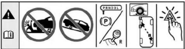
text_image
PRNO3L P RCAUTION!
Donotattempttoraisethevehiclebyjackington locationsotherthanthoseindicatedintheJacking Instructionsforthisvehicle.
- If equipped, remove the spare wheel, jack, and tools from storage.
- Using the lug wrench, loosen, but do not remove, the lug nuts by turning them counterclockwise one turn while the wheel is still on the ground.
- When changing the front wheel, assemble the jack driver to the jack and connect the jack driver to the extension tube. Place the jack under the axle as close to the tire as possible with the jack driver extending to the front. Connect the extension tubes and lug wrench.
060600714
JackWarningLabel

344 IN CASE OF EMERGENCY
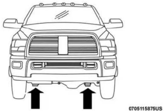
natural_image
Front view of a U.S. military-style vehicle with two upward arrows indicating side-mounted or sensor points (no text or symbols on the vehicle itself)FrontJackingLocationsRearJackingLocation
When changing a rear wheel, assemble the jack driver to the jack and connect the jack driver to the extension tubes. Securely place the jack under the sway bar bracket (unless both tires are flat on one side, then place jack under shock bracket) facing forward in vehicle. Connect the extension tubes and lug wrench.

natural_image
Top-down line drawing of a car's front and rear engine compartment with two upward arrows indicating movement or force (no text or symbols)Before raising the wheel off the ground, makes sure that the jack will not damage surrounding truck parts and adjust the jack position as required.
NOTE: If the jack will not lower by turning the dial (thumbwheel) by hand, it may be necessary to use the jack driver in order to lower the jack.
- By rotating the lug wrench clockwise, raise the vehicle until the wheel just clears the surface.

WARNING!
Raisingthevehiclehigherthannecessarycanmakethe vehiclelessstable.Itcouldslipoffthejackandhurt someonenearit.Raisethevehicleonlyenoughto removethetire.
- Remove the lug nuts and pull the wheel off. Install the spare wheel and lug nuts with the cone shaped end of the nuts toward the wheel on single rear wheel (SRW) models. On dual rear wheel models (DRW) the lug nuts are a two-piece assembly with a flat face. Lightly tighten the nuts. To avoid risk of forcing the vehicle off the jack, do not fully tighten the nuts until the vehicle has been lowered.
- Using the lug wrench, finish tightening the nuts using a crisscross pattern. For the proper lug nut torque specifications refer to "Wheel And Tire Torque Specifications" in "Technical Specifications." If in doubt about the correct tightness, have them checked with a torque wrench by an authorized dealer or at a service station.
WARNING!
Aloosetireorjackthrownforwardinacollisionor hardstop,couldendangertheoccupantsofthevehicle. Alwaysstowthejackpartsandthesparetireinthe placesprovided.
- Install wheel center cap (if equipped) and remove wheel blocks. Do not install chrome or aluminum wheel center caps on the spare wheel. This may result in cap damage.
- Lower the jack to its fully closed position. If the jack will not lower by turning the dial (thumbwheel) by hand, it may be necessary to use the jack driver in order to lower the jack. Stow the replaced tire, jack, and tools as previously described.
- Adjust the tire pressure when possible.
DualRearWheels
Slots in the wheels will assist in properly orienting the inner and outer wheels. Align these slots when assembling the wheels for best access to the tire valve on the inner wheel. The tires of both dual wheels must be completely off the ground when tightening to insure wheel centering and maximum wheel clamping.

346 IN CASE OF EMERGENCY
Dual wheel models require a special heavy-duty lug nut tightening adapter (included with the vehicle) to correctly tighten the lug nuts. Also, when it is necessary to remove and install dual rear wheels, use a proper vehicle lifting device.
NOTE: When installing a spare tire (if equipped) as part of a dual rear wheel end combination, the tire diameter of the two individual tires must be compared. If there is a significant difference, the larger tire should be installed in a front location. The correct direction of rotation for dual tire installations must also be observed.
It is recommended that wheel stud nuts be kept torqued to specifications at all times. Torque wheel stud nuts to specifications at each lubrication interval.
WheelNuts
All wheel nuts should be tightened occasionally to eliminate the possibility of wheel studs being sheared or the bolt holes in the wheels becoming elongated. This is especially important during the first few hundred miles/kilometers of operation to allow the wheel nuts to become properly set. All wheel nuts should first be firmly seated against the wheel. The wheel nuts should then be tightened to recommended torque. Tighten the wheel nuts to final torque in increments. Progress around the bolt circle, tightening the wheel nut opposite to the wheel nut just previously tightened until final torque is achieved.
To Stow The Flat Or Spare — If Equipped
Refer to Upfitters Body Builders Guide for information on stowing your spare tire (if equipped).
Hub Caps/Wheel Covers — If Equipped
The hub caps must be removed before raising the vehicle off the ground.
CAUTION!
Useextremec cautionwhenremovingthefrontandrear centercaps. Damagecanoccurtothecentercapand/or thewheelifscrewdrivertypetoolsareused. Apulling motion, notapryoffmotion, isrecommended to removethecaps.
For single rear wheel (SRW) models, use the flat blade on the end of the lug wrench to pull the hub cap off. Insert the blade end into the pull off notch and carefully pull the hub cap off with a back and forth motion.
On 3500 models with dual rear wheels (DRW), you must first remove the hub caps. The jack handle driver has a
hook at one end that will fit in the pull off notch of the rear hub caps. Position the hook and pull straight out on the ratchet firmly. The hub cap should pop off. The wheel skins can now be removed. For the front hub cap, use the flat blade on the end of the lug wrench to pull the caps off. The wheel skin can now be removed.
CAUTION!
- Useapullingmotiontoremovethehubcap.Donot useatwistingmotionwhenremovingthehubcap, damagetothehubcap;finishmayoccur.
- Therearhubcapsonthedualrearwheelhastwo pulloffnotches.Makesurethatthehookofthejack handledriverislocatedsquarelyinthecapnotch beforeattemptingtopulloff.
You must use the flat end of the lug wrench to pull off the wheel skins. Locate the hub cap pull notches (2 notches on each cap). Insert the flat tip completely and using a back and forth motion, loosen the wheel skin. Repeat this procedure around the tire until the skin pops off.
Replace the wheel skins first using a rubber mallet. When replacing the hub caps, tilt the cap retainer over the lug nut bolt circle and strike the high side down with a rubber mallet. Be sure that the hub caps and wheel skins are firmly seated around the wheel.
JUMP STARTING
If your vehicle has a discharged battery, it can be jump started using a set of jumper cables and a battery in another vehicle, or by using a portable battery booster pack. Jump starting can be dangerous if done improperly, so please follow the procedures in this section carefully.
WARNING!
Donotattemptjumpstartingifthebatteryisfrozen.It couldruptureorexplodeandcausepersonalinjury.
CAUTION!
Donotuseaportablebatteryboosterpackoranyother boostersourcewithasystemvoltagegreaterthan12 Voltsordamagetothebattery,startermotor,alternator orelectricalsystemmayoccur.
NOTE: When using a portable battery booster pack, follow the manufacturer's operating instructions and precautions.
348 IN CASE OF EMERGENCY
Preparations For Jump Start
The battery in your vehicle is located in the front of the engine compartment, behind the left headlight assembly.
NOTE: The positive battery post may be covered with a protective cap if equipped. Lift up on the cap to gain access to the positive battery post. Do not jump off fuses. Only jump directly off positive post which has a positive (+) symbol on or around the post.

natural_image
Technical diagram of a mechanical assembly with no visible text or symbolsPositiveJumpingLocation
WARNING!
• Takecaretoavoidtheradiatorcoolingfanwhenever thehoodisraised.Itcanstartanytimetheignition switchisON.Youcanbeinjuredbymovingfan blades.
- Removeanymetaljewelrysuchasrings, watch bandsandbraceletsthatcouldmakeaninadvertent electricalcontact. You could beseriously injured.
- Batteriescontainsulfuricacidthatcanburnyour skinoreyesandgeneratehydrogengaswhichis flammableandexplosive.Keepopenflamesor sparksawayfromthebattery.
- Apply the parking brake, shift the automatic transmission into PARK and turn the ignition OFF.
- Turn off the heater, radio, and all unnecessary electrical accessories.
- If using another vehicle to jump start the battery, park the vehicle within the jumper cables reach, apply the parking brake and make sure the ignition is OFF.
WARNING!
Donotallowvehiclestotoucheachotherasthiscould establishagroundconnectionandpersonalinjury couldresult.
Jump Starting Procedure
WARNING!
Failuretofollowthisjumpstartingprocedurecould resultinpersonalinjuryorpropertydamagedueto batteryexplosion.
CAUTION!
Failure to follow these procedures could result in damage to the charging system of the booster vehicle orthedischarged vehicle.
ConnectingTheJumperCables
- Connect the positive (+)end of the jumper cable to the positive (+)post of the discharged vehicle.
NOTE: Donotjumpoffuses. Only jump directly off positive post.
- Connect the opposite end of the positive (+)jumper cable to the positive (+)post of the booster battery.
- Connect the negative (-)end of the jumper cable to the negative (-)post of the booster battery.
- Connect the opposite end of the negative (-)jumper cable to a good engine ground (exposed metal part of the discharged vehicle's engine) away from the battery and the fuel injection system.
WARNING!
Donotconnectthejumpercabletothenegative(-)post ofthedischargedbattery. Theresultingelectricalspark couldcausethebatterytoexplodeandcouldresultin personalinjury. Onlyusethespecificgroundpoint,do notuseanyotherexposedmetalparts.
- Start the engine in the vehicle that has the booster battery, let the engine idle a few minutes, and then start the engine in the vehicle with the discharged battery.
CAUTION!
Donotconnectjumpercabletoanyofthefusesonthe positivebatteryterminal. Theresultingelectricalcurrentwillblowthefuse.
- Once the engine is started, remove the jumper cables in the reverse sequence:
DisconnectingTheJumperCables
- Disconnect the negative (-) end of the jumper cable from the engine ground of the vehicle with the discharged battery.
- Disconnect the opposite end of the negative (-)jumper cable from the negative (-)post of the booster battery.
- Disconnect the positive (+) end of the jumper cable from the positive (+) post of the booster battery.
- Disconnect the opposite end of the positive (+)jumper cable from the positive (+)post of the vehicle with the discharged battery.
If frequent jump starting is required to start your vehicle you should have the battery and charging system inspected at an authorized dealer.
CAUTION!
Accessoriespluggedintothevehiclepoweroutlets drawpowerfromthevehicle'sbattery,evenwhennot inuse(i.e.,cellulardevices,etc.).Eventually,ifplugged inlongenoughwithoutengineoperation,thevehicle's batterywilldischargesufficientlytodegradebattery lifeand/orpreventtheenginefromstarting.
IF YOUR ENGINE OVERHEATS
In any of the following situations, you can reduce the potential for overheating by taking the appropriate action.
- On the highways — slow down.
- In city traffic — while stopped, place the transmission in NEUTRAL, but do not increase the engine idle speed while preventing vehicle motion with the brakes.
NOTE: There are steps that you can take to slow down an impending overheat condition:
- If your air conditioner (A/C) is on, turn it off. The A/C system adds heat to the engine cooling system and turning the A/C off can help remove this heat.
- You can also turn the temperature control to maximum heat, the mode control to floor and the blower control to high. This allows the heater core to act as a supplement to the radiator and aids in removing heat from the engine cooling system.
WARNING!
Youorotherscanbebadlyburnedbyhotengine coolant(antifreeze)orsteamfromyourradiator.Ifyou seeorhearsteamcomingfromunderthehood,donot openthehooduntiltheradiatorhashadtimetocool. Nevertrytoopenacoolingsystempressurecapwhen theradiatororcoolantbottleishot.
CAUTION!
Drivingwithahotcoolingsystemcoulddamageyour vehicle.IfthetemperaturegaugereadsHOT(H),pull overandstopthevehicle.Idlethevehiclewiththeair conditionerturnedoffuntilthepointerdropsback intothenormalrange.IfthepointerremainsonHOT (H),andyouhearcontinuouschimes,turntheengine offimmediatelyandcallforservice.
If a malfunction occurs and the gear selector cannot be moved out of the PARK position, you can use the following procedure to temporarily move the gear selector:
- Turn the engine OFF.
- Firmly apply the parking brake.
- Tilt the steering wheel to the full up position.
- Press and maintain firm pressure on the brake pedal.
- Insert a screwdriver or similar tool into the access port (ringed circle) on the bottom of the steering column, and push and hold the override release lever up.
352 IN CASE OF EMERGENCY
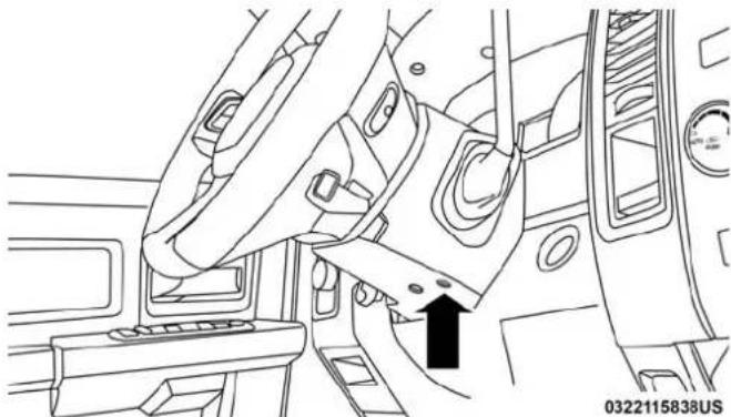
natural_image
Line drawing of a car interior showing seatbelt, door, and dashboard (no text or symbols)GearSelectorOverrideAccessPort
-
Move the gear selector to the NEUTRAL position.
-
The vehicle may then be started in NEUTRAL.
FREEING A STUCK VEHICLE
If your vehicle becomes stuck in mud, sand, or snow, it can often be moved using a rocking motion. Turn the steering wheel right and left to clear the area around the front wheels. Next, shift back and forth between DRIVE and REVERSE (with automatic transmission) or SECOND GEAR and REVERSE (with manual transmission) while gently pressing the accelerator. Use the least amount of accelerator pedal pressure that will maintain the rocking motion, without spinning the wheels or racing the engine.
NOTE: Push the "ESC Off" switch, to place the Electronic Stability Control (ESC) system in "Partial Off" mode, before rocking the vehicle. Refer to "Electronic Brake Control System" in "Safety" for further information. Once the vehicle has been freed, push the "ESC Off" switch again to restore "ESC On" mode.

WARNING!
Fastspinningtirescanbedangerous. Forcesgenerated byexcessivewheelspeedsmaycausedamage,oreven failure,oftheaxleandtires.Atirecouldexplodeand injuresomeone.Donotspinyourvehicle'swheels fasterthan30mph(48km/h)orforlongerthan30 secondscontinuouslywithoutstoppingwhenyouare stuckanddonotletanyonenearaspinningwheel,no matterwhatthespeed.
CAUTION!
- Racingtheengineorspinningthewheelsmaylead totransmissionoverheatingandfailure.Allowthe enginetoidlewiththetransmissioninNEUTRAL foratleastoneminuteaftereveryfiverocking-motioncycles.Thiswillminimizeoverheatingand reducetheriskofclutchortransmissionfailure duringprolongedeffortstofreeastuckvehicle.
- When "rocking" astuck vehicle by shifting between DRIVE/SECONDGEAR and REVERSE, donot spin the wheels faster than 15 mph (24 km/h), or drive-train damagemay result.
- Revvingtheengineorspinningthewheelstoofast mayleadtotransmissionoverheatingandfailure.It canalsodamagethetires.Donotspinthewheels above30mph(48km/h)whileingear(nottransmissionshiftingoccurring).
TOWING A DISABLED VEHICLE
This section describes procedures for towing a disabled vehicle using a commercial towing service. If the transmission and drivetrain are operable, disabled vehicles may also be towed as described under “Recreational Towing” in the “Starting And Operating” section.
| Towing Condition | Wheels OFFThe Ground | 2WDModels4WDModels | |
| Flat Tow NONE Iftransmissionisoperable: | Seeinstructionsin“RecreationalTowing”under“StartingAndOperating”•Auto Transmission in PARK•Manual Transmission in gear ( NOT NEUTRAL)•Transfer Case in NEUTRAL•Tow in forward direction | ||
| Wheel Lift Or Dolly Tow | Front NOTALLOWED | ||
| Rear OK NOTALLOWED | |||
| Flatbed ALL | BESTMETHOD | BESTMETHOD | |
Proper towing or lifting equipment is required to prevent damage to your vehicle. Use only tow bars and other equipment designed for this purpose, following equipment manufacturer's instructions. Use of safety chains is mandatory. Attach a tow bar or other towing device to main structural members of the vehicle, not to bumpers or associated brackets. State and local laws regarding vehicles under tow must be observed.
If you must use the accessories (wipers, defrosters, etc.) while being towed, the ignition must be in the ON/RUN mode, not the ACC mode.
If the key fob is unavailable or the vehicle's battery is discharged, refer to "Gear Selector Override" in this section for instructions on shifting the automatic transmission out of PARK for towing.
CAUTION!
- Donotuseslingtypeequipmentwhentowing. Vehicledamagemayoccur.
- Whensecuringthevehicletoaflatbedtruck, donot attachtofrontorrearsuspensioncomponents. Damagetoyourvehiclemayresultfromimpropertowing.
Two-Wheel Drive Models
The manufacturer recommends towing your vehicle with all four wheels OFF the ground using a flatbed.
If flatbed equipment is not available, and the transmission is operable, the vehicle may be towed (with the rear wheels on the ground) under the following conditions:
• The transmission must be in NEUTRAL.
- The towing speed must not exceed 30 mph (48 km/h).
- The towing distance must not exceed 15 miles (24 km).
If the transmission is not operable, or the vehicle must be towed faster than 30 mph (48 km/h) or farther than 15 miles (24 km), tow with the rear wheels OFFthe ground. Acceptable methods are to tow the vehicle on a flatbed, or with the front wheels raised and the rear wheels on a towing dolly, or (when using a suitable steering wheel stabilizer to hold the front wheels in the straight position) with rear wheels raised and the front wheels on the ground.
CAUTION!
Towing this vehicle inviolation of the aboverequirements can cause severe engine and/or transmission damage. Damage from impropertowing is not covered under the New Vehicle Limited Warranty.
Four-Wheel Drive Models
The manufacturer recommends towing with all wheels OFF the ground. Acceptable methods are to tow the vehicle on a flatbed or with one end of vehicle raised and the opposite end on a towing dolly.
If flatbed equipment is not available, and the transfer case is operable, the vehicle may be towed (in the forward direction, with ALL wheels on the ground), IF the transfer case is in NEUTRAL and the transmission is in PARK (for automatic transmissions) or in gear (NOT in NEUTRAL, for manual transmissions). Refer to "Recreational Towing" in "Starting And Operating" for further information and detailed instructions.
CAUTION!
- Frontorrearwheelliftsmustnotbeused(ifthe remainingwheelsareontheground).Internaldamagetothetransmissionortransfercasewilloccurif afrontorrearwheelliftisusedwhentowing.
- Towing this vehicle violation of the above requirements can cause severe transmission and/or transfer cased damage. Damage from impropertowing is not covered under the New Vehicle Limited Warranty.
Emergency Tow Hooks — If Equipped
Your vehicle may be equipped with emergency tow hooks.
NOTE: For off-road recovery, it is recommended to use both of the front tow hooks to minimize the risk of damage to the vehicle.
WARNING!
- Donotuseachainforfreeingastuckvehicle.Chains maybreak,causingseriousinjuryordeath.
- Standclearofvehicleswhenpullingwithtowhooks. Towstrapsmaybecomedisengaged,causingserious injury.
CAUTION!
Towhooksareforemergencyuseonly,torescuea vehiclestrandedoffroad.Donotusetowhooksfor towtruckhookuporhighwaytowing.Youcould damageyourvehicle.
ENHANCED ACCIDENT RESPONSE SYSTEM (EARS)
This vehicle is equipped with an Enhanced Accident Response System.
Please refer to "Occupant Restraint Systems" in "Safety" for further information on the Enhanced Accident Response System (EARS) function.
This vehicle is equipped with an Event Data Recorder (EDR). The main purpose of an EDR is to record data that will assist in understanding how a vehicle's systems performed under certain crash or near crash-like situations, such as an air bag deployment or hitting a road obstacle.
Please refer to "Occupant Restraint Systems" in "Safety" for further information on the Event Data Recorder (EDR).

SERVICING AND MAINTENANCE
CONTENTS
■SCHEDULED SERVICING....361
□Maintenance Plan....362
□Heavy Duty Use Of The Vehicle . . . . . . . . . . . . . . 365
■ENGINE COMPARTMENT....366
□6.4L Engine....366
□ Checking Oil Level — Gas Engine .....367
□Adding Washer Fluid....367
□Maintenance-Free Battery....367
■DEALER SERVICE....368
□Engine Oil — Gas Engine . . . . . . . . . . . . . . . . . . . . . . . . . . . . . . . . . . . . . . . . . . . . . . 369
□Engine Oil Filter....370
□Engine Air Cleaner Filter....370
□Air Conditioner Maintenance....373
□Front Driveshaft Lubrication — 2500/3500 (Four-Wheel Drive Models Only) .....378
□Accessory Drive Belt Inspection....379
□Body Lubrication....380
□Windshield Wiper Blades .....381
□Exhaust System....384
□ Cooling System ....386
□Brake System....390
□Automatic Transmission....391
☐Rear Axle And 4x4 Front Driving Axle Fluid Level....394
□Transfer Case....395
■HOISTING 395
SERVICING AND MAINTENANCE
■TIRES....396
□Tire Safety Information . . . . . . . . . . . . . . . . . . . . . . . . . . . . . . . . . . . . . . . . . . . . . 396
□Tires — General Information .....406
□Tire Types....412
□Spare Tires — If Equipped .....413
□Wheel And Wheel Trim Care . . . . . . . . . . . . . . . . . . . . . . . . . . . . . . . . . . . . . . . . . . . 416
□Tire Chains (Traction Devices) .....417
□Tire Rotation Recommendations .....418
■DEPARTMENT OF TRANSPORTATION UNIFORM TIRE QUALITY GRADES .....420
□Treadwear....421
□Traction Grades....421
□Temperature Grades....421
■STORING THE VEHICLE....422
■BODYWORK....422
□Protection From Atmospheric Agents .....422
□Body And Underbody Maintenance .....423
□Preserving The Bodywork....423
■INTERIORS....424
□Seats And Fabric Parts .....424
□Plastic And Coated Parts. . . . . . . . . . . . . . . . . . . . . . . . . . . . . . 425
□Leather Parts....426
□ Glass Surfaces .....426
SCHEDULED SERVICING
Your vehicle is equipped with an automatic oil change indicator system. The oil change indicator system will remind you that it is time to take your vehicle in for scheduled maintenance.
Based on engine operation conditions, the oil change indicator message will illuminate. This means that service is required for your vehicle. Operating conditions such as frequent short-trips, trailer tow, extremely hot or cold ambient temperatures, and E85 fuel usage will influence when the "Oil Change Required" message is displayed. Severe Operating Conditions can cause the change oil message to illuminate as early as 3,500 miles (5,600 km) since last reset. Have your vehicle serviced as soon as possible, within the next 500 miles (805 km).
Your authorized dealer will reset the oil change indicator message after completing the scheduled oil change. If a scheduled oil change is performed by someone other than your authorized dealer, the message can be reset by referring to the steps described under “Instrument Cluster Display” in “Getting To Know Your Instrument Panel” for further information.
GasolineEngines:
Under no circumstances should oil change intervals exceed 8,000 miles (13,000 km), twelve months or 350 hours of engine run time, whichever comes first. The 350 hours of engine run or idle time is generally only a concern for fleet customers.
SevereDuty:
Change Engine Oil at 4,000 miles (6,500 km) or 350 hours of engine run time if the vehicle is operated in a dusty and off road environment or is operated predominately at idle or very low engine RPM's. This type of vehicle use is considered Severe Duty.
OnceAMonthOrBeforeALongTrip:
- Check engine oil level
- Check windshield washer fluid level
- Check the tire inflation pressures and look for unusual wear or damage
- Check the fluid levels of the coolant reservoir, brake master cylinder, power steering and automatic transmission, and fill as needed
- Check function of all interior and exterior lights

362 SERVICING AND MAINTENANCE
Maintenance Plan
RequiredMaintenance
Refer to the maintenance plan on the following pages for required maintenance.
| AtEveryOilChangeIntervalAsIndicatedByOil ChangeIndicatorSystem: |
| • Change oil and filter. |
| • Rotate the tires. Rotate at the first sign of irregular wear,evenifitoccursbeforetheoilindicator systemturnson. |
| • Inspect engine cooling system protection and hoses. |
| • Inspect exhaust system. |
| • Inspect engine air cleaner if using in dusty or off-road conditions. |
| AtEveryOilChangeIntervalAsIndicatedByOil ChangeIndicatorSystem: |
| •Inspect battery and clean and tighten terminals as required. |
| •Inspect automatic transmission fluid if equipped with dipstick. |
| •Inspect brake pads, shoes, rotors, drums, hoses and park brake. |
| •Inspect front end, and lubricate — If equipped with serviceable fittings. |
| •Lube the front drive shaft fitting (4X4 models only). |
| Mileage or time passed (whichever comes first) | 20,000 | 30,000 | 40,000 | 50,000 | 60,000 | 70,000 | 80,000 | 90,000 | 100,000 | 110,000 | 120,000 | 130,000 | 140,000 | 150,000 |
| Or Years: | 2 3 4 | 5 6 7 | 8 9 10 | 11 12 | 13 14 | 15 | ||||||||
| Or Kilometers: | 32,000 | 48,000 | 64,000 | 80,000 | 96,000 | 112,000 | 128,000 | 144,000 | 160,000 | 176,000 | 192,000 | 208,000 | 224,000 | 240,000 |
| Additional Inspections | ||||||||||||||
| InspecttheCV/Universaljoints.XXXXX | ||||||||||||||
| Inspectfrontsuspension,tierodends,and replaceifnecessary. | X | X | X | X | X | X | X | |||||||
| Inspectthefrontandrearaxlesurfaces.If gearoilleakageissuspected,checkthe fluidlevel.Ifusingyourvehicleforpolice, taxi,fleet,off-roadorfrequenttrailertow-ing,changeaxlefluid. | X | X | X | X | X | X | X | |||||||
| Inspectthebrakelinings,parkingbrake function. | X | X | X | X | X | X | X | |||||||
| Additional Maintenance | ||||||||||||||
| Replaceengineairfilter. | XXXXX | |||||||||||||
| Replacesparkplugs.** | X | |||||||||||||
| Flushandreplacetheenginecoolantat 10yearsor150,000miles(240,000km) whichevercomesfirst. | X | X | ||||||||||||
| Changetheautomatictransmissionfluid (AS66RCTransmissionOnly). | X | X | X | |||||||||||

DEALER ePROCESS
| Mileage or time passed (whichever comes first) | 20,000 | 30,000 | 40,000 | 50,000 | 60,000 | 70,000 | 80,000 | 90,000 | 100,000 | 110,000 | 120,000 | 130,000 | 140,000 | 150,000 |
| Or Years: | 2 3 4 | 5 6 7 | 8 9 10 | 11 12 | 13 14 | 15 | ||||||||
| Or Kilometers: | 32,000 | 48,000 | 64,000 | 80,000 | 96,000 | 112,000 | 128,000 | 144,000 | 160,000 | 176,000 | 192,000 | 208,000 | 224,000 | 240,000 |
| Changetheautomatictransmissionfluid andsumpfilter(AS66RCTransmission Only). | X | X | ||||||||||||
| Changetheautomatictransmissionfluid andfilter(s)(66RFETransmissionOnly),if usingyourvehicleforpolice,taxi,fleet,or frequenttrailertowing. | X | X | ||||||||||||
| Changetheautomatictransmissionfluid andfilter(s)(66RFEtransmission). | X | |||||||||||||
| Inspectthetransfercasefluid,changefor anyofthefollowing:police,taxi,fleet,or frequenttrailertowing. | X | X | X | |||||||||||
| Changethetransfercasefluid.X | ||||||||||||||
| InspectandreplacePCVvalveifnecessary. | X |
** The spark plug change interval is mileage based only, yearly intervals do not apply.
X
WARNING!
- Youcanbebadlyinjuredworkingonorarounda motorvehicle.Doonlyserviceworkforwhichyou havetheknowledgeandtherightequipment.Ifyou haveanydoubtaboutyourabilitytoperforma servicejob,takeyourvehicletoacompetentmechanic.
- Failuretoproperlyinspectandmaintainyourvehicle couldresultinacomponentmalfunctionandeffect vehiclehandlingandperformance.Thiscouldcause anaccident.
Heavy Duty Use Of The Vehicle
Change engine oil at 4,000 miles (6,500 km) or 350 hours of engine run time if the vehicle is operated in a dusty and off road environment or is operated predominately at idle or only very low engine RPM's. This type of vehicle use is considered Severe Duty.
366 SERVICING AND MAINTENANCE
ENGINE COMPARTMENT
6.4L Engine
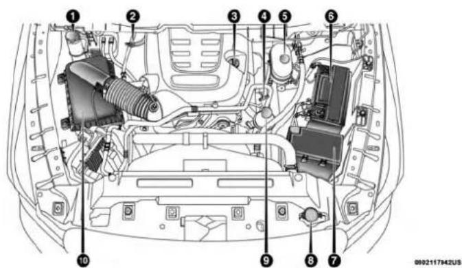
text_image
Technical diagram of a car engine bay with numbered components for identification1 — Engine Coolant Pressure Cap 6 — Battery
2 — Transmission Dipstick 7 — Power Distribution Center (Fuses)
3 — Engine Oil Fill 8 — Washer Solvent
4 — Engine Oil Dipstick 9 — Power Steering Fluid Reservoir
5 — Brake Fluid Reservoir 10 — Air Cleaner Filter

Checking Oil Level — Gas Engine
To assure proper lubrication of your vehicle's engine, the engine oil must be maintained at the correct level. Check the oil level at regular intervals, such as every fuel stop. The best time to check the engine oil level is about five minutes after a fully warmed up engine is shut off.
Checking the oil while the vehicle is on level ground will improve the accuracy of the oil level readings. Always maintain the oil level within the SAFE zone on the dipstick. Adding one quart of oil when the reading is at the bottom of the SAFE zone will result in a reading at the top of the safe zone on these engines.
CAUTION!
Overfillingorunderfillingwillcauseoilaerationor lossofoilpressure.Thiscoulddamageyouengine.
Adding Washer Fluid
The fluid reservoir is located under the hood and should be checked for fluid level at regular intervals. Fill the reservoir with windshield washer solvent only (not radiator anti-freeze). When refilling the washer fluid reservoir, take some washer fluid and apply it to a cloth or towel and wipe the wiper blades clean. This will help blade performance. To prevent freeze-up of your windshield washer system in cold weather, select a solution or mixture that meets or exceeds the temperature range of your climate. This rating information can be found on most washer fluid containers.
WARNING!
Commerciallyavailablewindshieldwashersolvents areflammable. They could ignite and burn you. Care must be exercised when filling or working around the washers solution.
After the engine has warmed up, operate the defroster for a few minutes to reduce the possibility of smearing or freezing the fluid on the cold windshield. Windshield washer solution used with water as directed on the container, aids cleaning action, reduces the freezing point to avoid line clogging, and is not harmful to paint or trim.
Maintenance-Free Battery
Your vehicle is equipped with a maintenance-free battery. You will never have to add water, nor is periodic maintenance required.

WARNING!
- Batteryfluidisacorrosiveacidsolutionandcan burnorevenblindyou.Donotallowbatteryfluidto contactyoureyes,skin,orclothing.Donotleanover abatterywhenattachingclamps.Ifacidsplashesin eyesoronskin,flushtheareaimmediatelywith largeamountsofwater.Referto"JumpStarting Procedure"in"InCaseOfEmergency"forfurther information.
- Batterygasisflammableandexplosive.Keepflame orsparksawayfromthebattery.Donotuseabooster batteryoranyotherboostersourcewithanoutput greaterthan12Volts.Donotallowcableclampsto toucheachother.
- Batteryposts,terminals,andrelatedaccessoriescontainleadandleadcompounds.Washhandsafter handling.
CAUTION!
- Itisessentialwhenreplacingthecablesonthe batterythatthepositivecableisattachedtothe positivepostandthenegativecableisattachedtothe
CAUTION!(Continued)
negativepost.Batterypostsaremarkedpositive(+) andnegative(-)andareidentifiedonthebattery case.Cableclampsshouldbetightontheterminal postsandfreeofcorrosion.
- Ifa "fastcharger" is used while the battery is in the vehicle, disconnect both vehicle battery cables before connecting the charger to the battery. Donotusea "fastcharger" to provide starting voltage.
DEALER SERVICE
An authorized dealer has the qualified service personnel, special tools, and equipment to perform all service operations in an expert manner. Service Manuals are available which include detailed service information for your vehicle. Refer to these Service Manuals before attempting any procedure yourself.
NOTE: Intentional tampering with emissions control systems may void your warranty and could result in civil penalties being assessed against you.
WARNING!
You can be badly injured working on or around a motor vehicle. Only doservicework for which you have the knowledge and the properequipment. If you have any doubt about your ability to perform a service job, take your vehicle to a competent mechanic.
Engine Oil — Gas Engine
ChangeEngineOil
The oil change indicator system will remind you that it is time to take your vehicle in for scheduled maintenance. Refer to "Scheduled Servicing" in this chapter for further information.
NOTE: Under no circumstances should oil change intervals exceed 8,000 miles (13,000 km), twelve months or 350 hours of engine run time, whichever comes first. The 350 hours of engine run or idle time is generally only a concern for fleet customers.
EngineOilSelection—6.4L
For best performance and maximum protection under all types of operating conditions, the manufacturer only recommends engine oils that are API Certified and meet the requirements of FCA Material Standard MS-12633.
AmericanPetroleumInstitute(API)EngineOil IdentificationSymbol

text_image
AMERICAN PETROLEUM INSTITUTE FOR GASOLINE ENGINES CERTIFIEDThis symbol means that the oil has been certified by the American Petroleum Institute (API). The manufacturer only recommends API Certified engine oils.
This symbol certifies 0W-20, 5W-20, 0W-30, 5W-30 and 10W-30 engine oils.
CAUTION!
Donotusechemicalflushesinyourengineoilasthe chemicalscandamageyourengine.Suchdamageisnot coveredbytheNewVehicleLimitedWarranty.

370 SERVICING AND MAINTENANCE
EngineOilViscosity(SAEGrade)—6.4LEngine
Use Mopar SAE 0W-40 engine oil approved to FCA Material Standard MS-12633 such as Pennzoil Ultra equivalent is recommended for all operating temperatures.
The engine oil filler cap also shows the recommended engine oil viscosity for your engine. For information on engine oil filler cap location, refer to the “Engine Compartment” illustration in this section.
Lubricants which do not have both the engine oil certification mark and the correct SAE viscosity grade number should not be used.
SyntheticEngineOils
You may use synthetic engine oils provided the recommended oil quality requirements are met, and the recommended maintenance intervals for oil and filter changes are followed.
Synthetic engine oils which do not have both the engine oil certification mark and the correct SAE viscosity grade number should not be used.
MaterialsAddedToEngineOil
The manufacturer strongly recommends against the addition of any additives (other than leak detection dyes) to the engine oil. Engine oil is an engineered product and its performance may be impaired by supplemental additives.
DisposingOfUsedEngineOilAndOilFilters
Care should be taken in disposing of used engine oil and oil filters from your vehicle. Used oil and oil filters, indiscriminately discarded, can present a problem to the environment. Contact an authorized dealer, service station or governmental agency for advice on how and where used oil and oil filters can be safely discarded in your area.
Engine Oil Filter
The engine oil filter should be replaced with a new filter at every engine oil change.
EngineOilFilterSelection
This manufacturer's engines have a full-flow type disposable oil filter. Use a filter of this type for replacement. The quality of replacement filters varies considerably. Only high quality filters should be used to assure most efficient service. Mopar engine oil filters are high quality oil filters and are recommended.
Engine Air Cleaner Filter
Refer to the "Maintenance Plan" in this section for the proper maintenance intervals.
NOTE: Be sure to follow the "Severe Duty Conditions" maintenance interval if applicable.
WARNING!
Theairinductionsystem(aircleaner,hoses,etc.)can provide a measure of protection in the case of engine backfire. Donotremovetheairinduction system (air cleaner, hoses, etc.) unless such removal is necessary for repair or maintenance. Makes sure that no one is near the engine compartment before starting the vehicle with the air induction system (aircleaner, hoses, etc.) removed. Failure to dosocan result in serious personal injury.
EngineAirCleanerFilterSelection
The quality of replacement engine air cleaner filters varies considerably. Only high quality filters should be used to assure most efficient service. Mopar engine air cleaner filters are a high quality filter and are recommended.
EngineAirCleanerFilterInspection and Replacement
Inspect engine air cleaner filter for dirt and or debris, if you find evidence of either dirt or debris you should change your air cleaner filter.
EngineAirCleanerFilterRemoval
- Release the spring clips from the air cleaner cover.
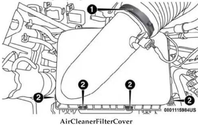
text_image
AirCleanerFilterCover 0801115984US1 — Clean Air Hose Clamp
2 — Spring Clips

372 SERVICING AND MAINTENANCE
- Lift the air cleaner cover to access the air cleaner filter.
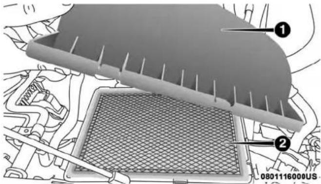
text_image
① ② 0801116000USOpenAirCleanerFilterAssembly
1 — Air Cleaner Cover
2 — Air Cleaner Filter
- Remove the air cleaner filter element from the housing assembly.

natural_image
Close-up of a textured surface with numbered annotations (1 and 2), no readable text or symbols beyond labelsAirCleanerFilter
1 — Air Cleaner Filter
2 — Air Cleaner Filter Inspection Surface
EngineAirCleanerFilterInstallation
NOTE: Inspect and clean the housing if dirt or debris is present before replacing the air filter element.
- Install the air cleaner filter element into the housing assembly with the air cleaner filter inspection surface facing downward.

- Install the air cleaner cover onto the housing assembly locating tabs.
- Latch the spring clips and lock the air cleaner cover to the housing assembly.
Air Conditioner Maintenance
For best possible performance, your air conditioner should be checked and serviced by an authorized dealer at the start of each warm season. This service should include cleaning of the condenser fins and a performance test. Drive belt tension should also be checked at this time.
WARNING!
- Useonlyrefrigerantsandcompressorlubricantsapprovedbythemanufacturerforyourairconditioning system.Someunapprovedrefrigerantsareflammableandcanexplode,injuringyou.Otherunapprovedrefrigerantsorlubricantscancausethesystemtofail,requiringcostlyrepairs.Referto WarrantyInformationBook,forfurtherwarranty information.
WARNING!(Continued)
- The air conditioningsystem contains refrigerant under high pressure. To avoid risk of personal injury or damage to the system, adding refrigerant or any repair requiring linestobed disconnected should be done by an experienced technician.
CAUTION!
Donotusechemicalflushesinyourairconditioning systemasthechemicalscandamageyourairconditioningcomponents.Suchdamageisnotcoveredbythe NewVehicleLimitedWarranty.
Refrigerant Recovery And Recycling R-134a—If Equipped
R-134a Air Conditioning Refrigerant is a hydrofluorocarbon (HFC) that is an ozone-friendly substance. The manufacturer recommends that air conditioning service be performed by an authorized dealer or other service facilities using recovery and recycling equipment.
NOTE: Use only manufacturer approved A/C system PAG compressor oil and refrigerants.
(Continued)

374 SERVICING AND MAINTENANCE
Refrigerant Recovery And Recycling—R-1234yf
R-1234yf Air Conditioning Refrigerant is a hydrofluoroolefin (HFO) that is endorsed by the Environmental Protection Agency and is an ozone-friendly substance with a low global-warming potential. The manufacturer recommends that air conditioning service be performed by an authorized dealer using recovery and recycling equipment.
NOTE: Use only manufacturer approved A/C system PAG compressor oil, and refrigerants.
CabinFilterReplacement(A/CAirFilter)
Refer to the "Maintenance Plan" for the proper maintenance intervals.
WARNING!
Donotremovethecabinairfilterwhilethevehicleis running,orwhiletheignitionisintheACCorON/RUNmode.Withthecabinairfilterremovedandthe bloweroperating,theblowercancontacthandsand maypropeldirtanddebrisintoyoureyes,resultingin personalinjury.
The cabin air filter is located in the fresh air inlet behind the glove compartment. Perform the following procedure to replace the filter:
- Open the glove compartment and remove all contents.
- With the glove compartment door open, remove the glove compartment tension tether and tether clip by sliding the clip toward the face of the glove compartment door. Lift the clip out of glove compartment door and release into dash panel.
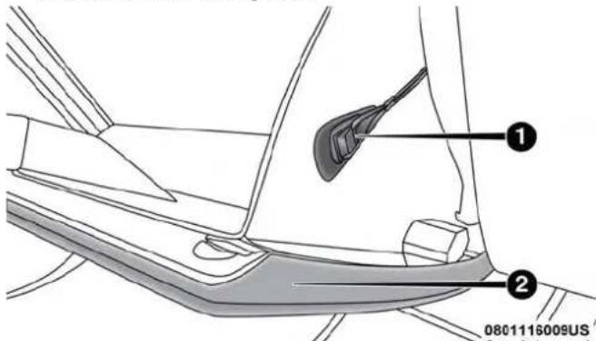
text_image
0801116009USRightSideOfGloveCompartment
1 — Glove Compartment Tension Tether
2 — Glove Compartment Door

SERVICING AND MAINTENANCE 375
- There are glove compartment travel stops on both sides of the glove compartment door, push inward on both sides of the glove compartment to release the glove compartment travel stops.
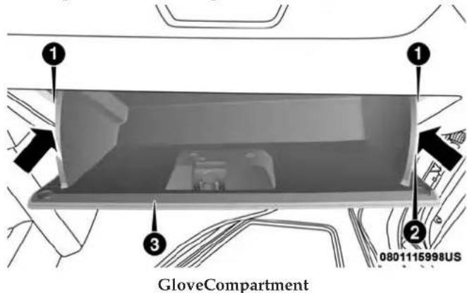
text_image
GloveCompartment 0801115998US1 — Glove Compartment Travel Stops
2 — Glove Compartment Tension Tether
3 — Glove Compartment Door
-
Disengage the glove compartment door from its hinges by opening the glove compartment past the travel stop and pulling it toward you.
-
Remove the filter cover by pushing in on the finger tabs on each end of the filter cover.

text_image
0801115993US FilterCover
376 SERVICING AND MAINTENANCE
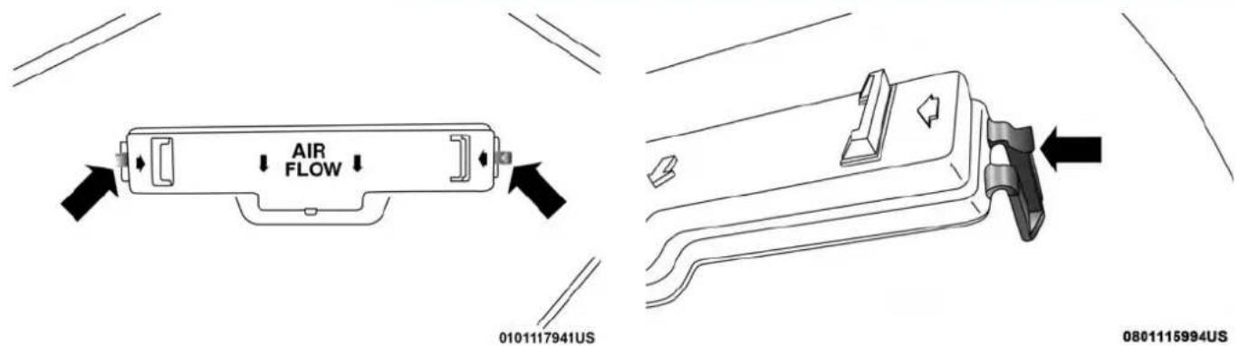
text_image
AIR FLOW 0101117941US 0801115994USFingerTabsFingerTab

- Remove the cabin air filter by pulling it straight out of the housing.
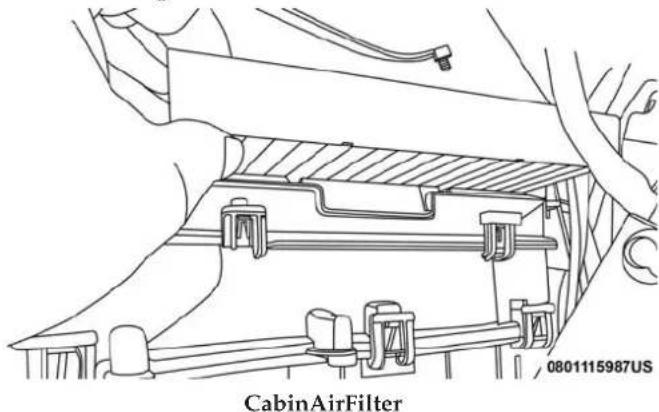
text_image
CabinAirFilter 0801115987US-
Install the cabin air filter with the arrow on the filter pointing toward the floor. When installing the filter cover, press on each end until you hear an audible click.
-
Reinstall the glove compartment on the hinges.

text_image
GloveCompartmentInstallation 0801115997USCAUTION!
Thecabinairfilterisidentifiedwithanarrowto indicateairflowdirectionthroughthefilter.Failureto properlyinstallthefilterwillresultintheneedto replaceitmoreoften.

378 SERVICING AND MAINTENANCE
- Pull the tension tether outward and reinstall the glove compartment past the travel stops by pushing in on the glove compartment sides.
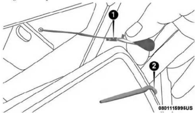
text_image
Technical diagram showing mechanical components with numbered annotations and a timestamp at the bottomRightSideOfGloveCompartment
1 — Glove Compartment Tension Tether
2 — Glove Compartment Travel Stop
NOTE: Ensure the glove compartment door hinges and glove compartment travel stops are fully engaged.
- Reattach the glove compartment tension tether by inserting the tether clip in the glove compartment and sliding the clip away from the face of the glove compartment door.
Front Driveshaft Lubrication — 2500/3500 (Four-Wheel Drive Models Only)
Lubricate the front driveshaft grease fitting at each oil change.

natural_image
Technical line drawing of a mechanical assembly with no visible text or symbols0801115996US
FrontDriveShaftDoubleCardanJoint

The grease fitting is located at the rear of the front driveshaft, near the centering mechanism of double cardan joint. Refer to the "Maintenance Plan" for the proper maintenance intervals. Use Mopar Type MS-6560 (lithium-based grease), or equivalent.

text_image
1 2 3 DoubleCardanJoint 0801115992US1 — Double Cardan Joint
2 — Grease Fitting
3 — Exploded View – Grease Fitting
Accessory Drive Belt Inspection
WARNING!
- Donotattempttoinspectanaccessorydrivebelt withvehiclerunning.
- When working near the radiator cooling fan, disconnect the fan motor lead. The fan is temperature controlled and can start at any time regardless of ignition mode. You could be injured by them moving fan blades.
- You can be badly injured working on or around a motor vehicle. Only doservicework for which you have the knowledge and the proper equipment. If you have any doubt about your ability to perform a service job, take your vehicle to a competent mechanic.
When inspecting accessory drive belts, small cracks that run across ribbed surface of belt from rib to rib, are considered normal. These are not a reason to replace belt. However, cracks running along a rib (not across) are not normal. Any belt with cracks running along a rib must be replaced. Also have the belt replaced if it has excessive wear, frayed cords or severe glazing.
380 SERVICING AND MAINTENANCE

natural_image
Technical line drawing of mechanical components with no visible text or symbolsAccessoryBelt(SerpentineBelt)
Conditions that would require replacement:
- Rib chunking (one or more ribs has separated from belt body)
- Rib or belt wear
- Longitudinal belt cracking (cracks between two ribs)
- Belt slips
- "Groove jumping"(belt does not maintain correct position on pulley)
- Belt broken (note: identify and correct problem before new belt is installed)
- Noise (objectionable squeal, squeak, or rumble is heard or felt while drive belt is in operation)
Some conditions can be caused by a faulty component such as a belt pulley. Belt pulleys should be carefully inspected for damage and proper alignment.
Belt replacement on some models requires the use of special tools, we recommend having your vehicle serviced at an authorized dealer.
Body Lubrication
Locks and all body pivot points, including such items as seat tracks, door hinge pivot points and rollers, liftgate, tailgate, decklid, sliding doors and hood hinges, should be lubricated periodically with a lithium based grease, such as Mopar Spray White Lube to assure quiet, easy operation and to protect against rust and wear. Prior to the application of any lubricant, the parts concerned should be wiped clean to remove dust and grit; after lubricating excess oil and grease should be removed. Particular attention should also be given to hood latching components to ensure proper function. When performing other underhood services, the hood latch, release mechanism and safety catch should be cleaned and lubricated.

The external lock cylinders should be lubricated twice a year, preferably in the Fall and Spring. Apply a small amount of a high quality lubricant, such as Mopar Lock Cylinder Lubricant directly into the lock cylinder.
Windshield Wiper Blades
Clean the rubber edges of the wiper blades and the windshield periodically with a sponge or soft cloth and a mild nonabrasive cleaner. This will remove accumulations of salt or road film.
Operation of the wipers on dry glass for long periods may cause deterioration of the wiper blades. Always use washer fluid when using the wipers to remove salt or dirt from a dry windshield.
Avoid using the wiper blades to remove frost or ice from the windshield. Keep the blade rubber out of contact with petroleum products such as engine oil, gasoline, etc.
NOTE: Life expectancy of wiper blades varies depending on geographical area and frequency of use. Poor performance of blades may be present with chattering, marks, water lines or wet spots. If any of these conditions are present, clean the wiper blades or replace as necessary.
The wiper blades and wiper arms should be inspected periodically, not just when wiper performance problems are experienced. This inspection should include the following points:
- Wear or uneven edges
- Foreign material
- Hardening or cracking
- Deformation or fatigue
If a wiper blade or wiper arm is damaged, replace the affected wiper arm or blade with a new unit. Do not attempt to repair a wiper arm or blade that is damaged.
WiperBladeRemoval/Installation
CAUTION!
Donotallowthewiperarmtospringbackagainstthe glass without the wiper blade in place or the glass may bedamaged.
382 SERVICING AND MAINTENANCE
- Lift the wiper arm to raise the wiper blade off of the glass, until the wiper arm is in the full up position.

text_image
WindshieldWiperArm 0801116014US1—Wiper
2 — Locking Tab
3 — WiperArm
- To disengage the wiper blade from the wiper arm, flip up the locking tab.
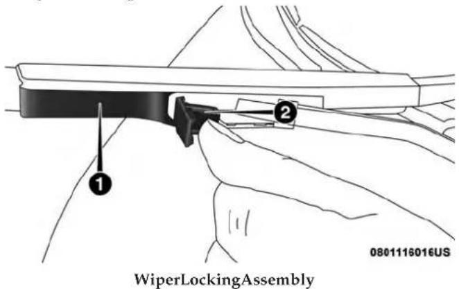
text_image
WiperLockingAssembly 0801116016US1—Wiper
2 — Locking Tab
SERVICING AND MAINTENANCE 383
- Tilt the lower end of the wiper blade away from the arm and use one finger push the release tab toward the wiper arm.
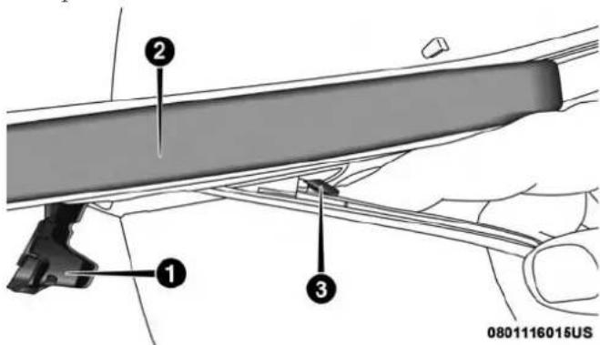
text_image
0801116015USWiperDisengaging
1 — Locking Tab
2 — Wiper
3 — Release Tab
-
Slide the wiper blade down towards the base of the wiper arm.
-
With the wiper blade disengaged, remove the wiper blade from the wiper arm by holding the wiper arm with one hand and separating the wiper blade from the wiper arm with the other hand (move the wiper blade down toward the base of the wiper arm and away from the J hook in the end of the wiper arm).
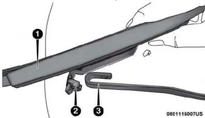
text_image
① ② ③ 0801116007USRemovingWiperFromWiperArm
1 — Wiper
2 — Locking Tab
3 — Wiper Arm J Hook
- Gently lower the wiper arm onto the glass.

384 SERVICING AND MAINTENANCE
InstallingTheFrontWipers
- Lift the wiper arm off of the glass, until the wiper arm is in the full up position.
- Position the wiper blade under the hook on the tip of the wiper arm with the wiper locking tab open.
- Insert the receiver bracket on the wiper assembly into the hook on the tip of the arm through the opening in the wiper blade under the locking tab.
- Slide the wiper blade up into the hook on the wiper arm until it is latched (engagement will be accompanied by an audible click). Fold down the latch release tab and snap it into its locked position.
- Gently lower the wiper blade onto the glass.
Exhaust System
The best protection against carbon monoxide entry into the vehicle body is a properly maintained engine exhaust system.
If you notice a change in the sound of the exhaust system; or if the exhaust fumes can be detected inside the vehicle; or when the underside or rear of the vehicle is damaged;
have an authorized technician inspect the complete exhaust system and adjacent body areas for broken, damaged, deteriorated, or mispositioned parts. Open seams or loose connections could permit exhaust fumes to seep into the passenger compartment. In addition, have the exhaust system inspected each time the vehicle is raised for lubrication or oil change. Replace as required.
WARNING!
- Exhaustgasescaninjureorkill. They contain carbon monoxide(CO), which is colorless and odorless. Breathing it can make you unconscious and can eventually poison you. To avoid breathing CO, refer to "Safety Tips" in "Safety" for further information.
- Ahotexhaustsystemcanstartafireifyouparkover materialsthatcanburn.Suchmaterialsmightbe grassorleavescomingintocontactwithyourehaust system.Donotparkoroperateyourvehicleinareas whereyourehaustsystemcancontactanythingthat canburn.
CAUTION!
- The catalytic converter requires the use of unleaded fuel only. Leaded gasoline will destroy the effectiveness of the catalyst as an emissions control device and may seriously reduce engine performance and causes serious damage to the engine.
- Damagethecatalyticconvertercanresultifyour vehicleisnotkeptinproperoperatingcondition.In theeventofenginemalfunction,particularlyinvolvingenginemisfireorotherapparentlossofperformance,haveyourvehicleservicedpromptly.Continuedoperationofyourvehiclewithasevere malfunctioncouldcausetheconvertertooverheat, resultinginpossibledamagetotheconverterand vehicle.
Under normal operating conditions, the catalytic converter will not require maintenance. However, it is important to keep the engine properly tuned to assure proper catalyst operation and prevent possible catalyst damage.
NOTE: Intentional tampering with emissions control systems can result in civil penalties being assessed against you.
In unusual situations involving grossly malfunctioning engine operation, a scorching odor may suggest severe and abnormal catalyst overheating. If this occurs, stop the vehicle, turn off the engine and allow it to cool. Service, including a tune-up to manufacturer's specifications, should be obtained immediately.
To minimize the possibility of catalytic converter damage:
- Do not interrupt the ignition when the transmission is in gear and the vehicle is in motion.
- Do not try to start the vehicle by pushing or towing the vehicle.
- Do not idle the engine with any ignition components disconnected or removed, such as when diagnostic testing, or for prolonged periods during very rough idle or malfunctioning operating conditions.
Cooling System
WARNING!
- Youorotherscanbebadlyburnedbyhotengine coolant(antifreeze)orsteamfromyourradiator.If youseeorhearsteamcomingfromunderthehood, donotopenthehooduntiltheradiatorhashadtime tocool.Neveropenacoolingsystempressurecap whentheradiatororcoolantbottleishot.
- Keephands, tools, clothing, and jewelry away from the radiator cooling fan when the hood is raised. The fan starts automatically and may start at any time, whether the engine is running or not.
- When working near the radiator cooling fan, disconnect the fan motor lead to turn the ignition to the OFF mode. The fan is temperature controlled and can start at any time the ignition is in the ON mode.
EngineCoolantChecks
Check the engine coolant (antifreeze) protection every 12 months (before the onset of freezing weather, where applicable). If the engine coolant (antifreeze) is dirty or rusty in appearance, the system should be drained, flushed and refilled with fresh coolant. Check the front of the condenser (if equipped) or radiator for any accumulation of bugs, leaves, etc. If dirty, clean by gently spraying water from a garden hose vertically down the face of the A/C condenser (if equipped) or the back of the radiator core.
Check the engine cooling system hoses for brittle rubber, cracking, tears, cuts and tightness of the connection at the coolant recovery bottle and radiator. Inspect the entire system for leaks.
DO NOT REMOVE THE COOLANT PRESSURE CAP WHEN THE COOLING SYSTEM IS HOT.
CoolingSystem—Drain, Flush And Refill
NOTE: Some vehicles require special tools to add coolant properly. Failure to fill these systems properly could lead to severe internal engine damage. If any coolant is needed to be added to the system please contact an authorized dealer.
If the engine coolant (antifreeze) is dirty or contains visible sediment, have an authorized dealer clean and flush with OAT coolant (antifreeze) (conforming to MS.90032).
Refer to the "Maintenance Plan" in this section for the proper maintenance intervals.
SelectionOfCoolant
Refer to "Fluids And Lubricants" in "Technical Specifications" for further information.
NOTE:
- Mixing of engine coolant (antifreeze) other than specified Organic Additive Technology (OAT) engine coolant (antifreeze), may result in engine damage and may decrease corrosion protection. Organic Additive Technology (OAT) engine coolant is different and should not be mixed with Hybrid Organic Additive Technology (HOAT) engine coolant (antifreeze) or any “globally compatible” coolant (antifreeze). If a non-OAT engine coolant (antifreeze) is introduced into the cooling system in an emergency, the cooling system will need to be drained, flushed, and refilled with fresh OAT coolant (conforming to MS.90032), by an authorized dealer as soon as possible.
- Do not use water alone or alcohol-based engine coolant (antifreeze) products. Do not use additional rust inhibitors or antirust products, as they may not be compatible with the radiator engine coolant and may plug the radiator.
- This vehicle has not been designed for use with propylene glycol-based engine coolant (antifreeze). Use of propylene glycol-based engine coolant (antifreeze) is not recommended.
- Some vehicles require special tools to add coolant properly. Failure to fill these systems properly could lead to severe internal engine damage. If any coolant is needed to be added to the system please contact an authorized dealer.
AddingCoolant
Your vehicle has been built with an improved engine coolant (OAT coolant conforming to MS.90032) that allows extended maintenance intervals. This engine coolant (anti-freeze) can be used up to ten years or 150,000 miles (240,000 km) before replacement. To prevent reducing this extended maintenance period, it is important that you use the same engine coolant (OAT coolant conforming to MS.90032) throughout the life of your vehicle.
Please review these recommendations for using Organic Additive Technology (OAT) engine coolant (antifreeze) that meets the requirements of FCA Material Standard MS.90032. When adding engine coolant (antifreeze):
- We recommend using Mopar Antifreeze/Coolant 10 Year/150,000 Mile (240,000 km) Formula OAT (Organic Additive Technology) that meets the requirements of FCA Material Standard MS.90032.
388 SERVICING AND MAINTENANCE
- Mix a minimum solution of 50% OAT engine coolant that meets the requirements of FCA Material Standard MS.90032 and distilled water. Use higher concentrations (not to exceed 70%) if temperatures below -34^ ( -37^ ) are anticipated. Please contact an authorized dealer for assistance.
- Use only high purity water such as distilled or deionized water when mixing the water/engine coolant (anti-freeze) solution. The use of lower quality water will reduce the amount of corrosion protection in the engine cooling system.
NOTE:
- It is the owner's responsibility to maintain the proper level of protection against freezing according to the temperatures occurring in the area where the vehicle is operated.
- Some vehicles require special tools to add coolant properly. Failure to fill these systems properly could lead to severe internal engine damage. If any coolant is needed to be added to the system, please contact a local authorized dealer.
- Mixing engine coolant (antifreeze) types is not recommended and can result in cooling system damage. If
age. If
HOAT and OAT coolant are mixed in an emergency, have a authorized dealer drain, flush, and refill with OAT coolant (conforming to MS.90032) as soon as possible.
CoolingSystemPressureCap
The cap must be fully tightened to prevent loss of engine coolant (antifreeze), and to ensure that engine coolant (antifreeze) will return to the radiator from the coolant expansion bottle/recovery tank if so equipped.
The cap should be inspected and cleaned if there is any accumulation of foreign material on the sealing surfaces.
WARNING!
- Donotopenhotenginecoolingsystem.Neveradd enginecoolant(antifreeze)whentheengineisoverheated.Donotloosenorremovethecaptocoolan overheatedengine.Heatcausespressureobuildup inthecoolingsystem.Topreventscaldingorinjury, donotremovethepressurecapwhilethesystemis hotorunderpressure.
- Donotuseapressurecapotherthantheonespecifiedforyourvehicle.Personalinjuryorengine damagemayresult.
DEALER ePROCESS
DisposalOfUsedCoolant
Used ethylene glycol-based coolant (antifreeze) is a regulated substance requiring proper disposal. Check with your local authorities to determine the disposal rules for your community. To prevent ingestion by animals or children, do not store ethylene glycol-based coolant in open containers or allow it to remain in puddles on the ground. If ingested by a child or pet, seek emergency assistance immediately. Clean up any ground spills immediately.
CheckingCoolantLevel—6.4LEngine
The level of the coolant in the pressurized coolant bottle should be between the "MIN" and "MAX" range on the bottle when the engine is cold.
The radiator normally remains completely full, so there is no need to remove the cap unless checking for coolant freeze point or replacing engine coolant (antifreeze). Advise your service attendant of this. As long as the engine operating temperature is satisfactory, the coolant bottle need only be checked once a month. When additional engine coolant (antifreeze) is needed to maintain the proper level, it should be added to the coolant bottle. Do not overfill.
PointsToRemember
NOTE: When the vehicle is stopped after a few miles/kilometers of operation, you may observe vapor coming from the front of the engine compartment. This is normally a result of moisture from rain, snow, or high humidity accumulating on the radiator and being vaporized when the thermostat opens, allowing hot engine coolant (anti-freeze) to enter the radiator.
If an examination of your engine compartment shows no evidence of radiator or hose leaks, the vehicle may be safely driven. The vapor will soon dissipate.
- Do not overfill the coolant expansion bottle.
- Check the coolant freeze point in the radiator and in the coolant expansion bottle. If engine coolant (antifreeze) needs to be added, the contents of the coolant expansion bottle must also be protected against freezing.
- If frequent engine coolant (antifreeze) additions are required, the cooling system should be pressure tested for leaks.
390 SERVICING AND MAINTENANCE
- Maintain engine coolant (antifreeze) concentration at a minimum of 50% OAT coolant (conforming to MS.90032) and distilled water for proper corrosion protection of your engine which contains aluminum components.
- Make sure that the coolant expansion bottle overflow hoses are not kinked or obstructed.
- Keep the front of the radiator clean. If your vehicle is equipped with air conditioning, keep the front of the condenser clean.
- Do not change the thermostat for Summer or Winter operation. If replacement is ever necessary, install ONLY the correct type thermostat. Other designs may result in unsatisfactory engine coolant (antifreeze) performance, poor gas mileage, and increased emissions.
Brake System
In order to assure brake system performance, all brake system components should be inspected periodically. Refer to the “Maintenance Plan” in this section for the proper maintenance intervals.
WARNING!
Ridingthebrakescanleadtobrakefailureandpossiblyacollision.Drivingwithyourfootrestingorridingonthebrakepedalcanresultinabnormallyhighbraketemperatures,excessiveliningwear,andpossiblebrakedamage.Youwouldnothaveyourfullbrakingcapacityinanemergency.
FluidLevelCheck—BrakeMasterCylinder
The fluid level of the master cylinder should be checked when performing under the hood service or immediately if the brake system warning lamp indicates system failure.
The brake master cylinder has a translucent plastic reservoir. On the outboard side of the reservoir, there is a "MAX" mark and a "MIN" mark. The fluid level must be kept within these two marks. Do not add fluid above the MAX mark because leakage may occur at the cap.
With disc brakes the fluid level can be expected to fall as the brake linings wear. However, an unexpected drop in fluid level may be caused by a leak and a system check should be conducted.

Refer to "Fluids And Lubricants" in "Technical Specifications" for further information.
WARNING!
- Useonlymanufacturer's recommended brakefluid. Referto "FluidsAndLubricants" in "Technical Specifications" for further information. Using the wrong type of brakefluid can severely damage your brakesystem and/or impair performance. The property of brakefluid for your vehicle is also identified on the original factory installed hydraulic master cylinder reservoir.
- To avoid contamination from foreign matter or moisture, use only new brake fluid or fluid that has been inatightly closed container. Keep them mastery cylinder reservoir or secure data all times. Brake fluid in a open container absorbs moisture from their resulting in alower boiling point. This may cause it to oil unexpectedly during hard or prolonged braking, resulting in sudden brake failure. This could result in a collision.
WARNING!(Continued)
• Overfillingthebrakefluidreservoircanresultin spillingbrakefluidonhotengineparts, causing the brakefluidtocatchfire. Brakefluidcanalsodamage painted and vinylsurfaces, careshouldbetakento avoid its contact with thesesurfaces.
- Donotallowpetroleumbasedfluidtocontaminate thebrakefluid.Brakesealcomponentscouldbe damaged,causingpartialorcompletebrakefailure. Thiscouldresultinacollision.
Automatic Transmission
SelectionOfLubricant
It is important to use the proper transmission fluid to ensure optimum transmission performance and life. Use only the manufacturer's specified transmission fluid. Refer to "Fluids And Lubricants" in "Technical Specifications". It is important to maintain the transmission fluid at the correct level using the recommended fluid. No chemical flushes should be used in any transmission; only the approved lubricant should be used.
(Continued)

CAUTION!
Usingatransmissionfluidotherthanthemanufacturer'srecommendedfluidmaycausedeteriorationin transmissionshiftqualityand/or torqueconverter shudder, and will require more frequent fluid and filter changes. Referto "FluidsAndLubricants" in "TechnicalSpecifications" for fluids specifications.
SpecialAdditives
The manufacturer strongly recommends against using any special additives in the transmission. Automatic Transmission Fluid (ATF) is an engineered product and its performance may be impaired by supplemental additives. Therefore, do not add any fluid additives to the transmission. The only exception to this policy is the use of special dyes for diagnosing fluid leaks. Avoid using transmission sealers as they may adversely affect seals.
CAUTION!
Donotusechemicalflushesinyourtransmissionas thechemicalscandamageyourtransmissioncomponents.SuchdamageisnotcoveredbytheNewVehicle LimitedWarranty.
FluidLevelCheck
Check the fluid level when the engine is fully warmed up and the transmission fluid is at normal operating temperature. Driving with an improper fluid level will greatly reduce the life of the transmission and of the fluid. Check the fluid level whenever the vehicle is serviced.
FluidLevelCheck—Procedure
It is best to check the fluid level when the transmission is at normal operating temperature (170-180°F / 77-82°C for 66RFE transmission, or 158-176°F / 70-80°C for AS66RC transmission). This normally occurs after at least 15 miles (25 km) of driving. At normal operating temperature the fluid cannot be held comfortably between the fingertips. You can read the transmission sump temperature in the instrument cluster display (refer to "Instrument Cluster Display" in "Getting To Know Your Instrument Panel" for further information).
Use the following procedure to check the transmission fluid level properly:
- Monitor the transmission temperature using the instrument cluster display, and operate the vehicle as required to reach the normal operating temperature. If the transmission is not functioning properly, or the vehicle
cannot be driven, see the NOTE and CAUTION below about checking the fluid level at colder temperatures.
- Park the vehicle on level ground.
- Run the engine at normal idle speed for at least 60 seconds, and leave the engine running for the rest of this procedure.
- Fully apply the parking brake and press the brake pedal.
- Place the gear selector momentarily into each gear position (allowing time for the transmission to fully engage in each position), ending with the transmission in PARK.
- Wipe the area around the dipstick clean to prevent dirt from entering the transmission.
- Remove the dipstick, wipe it clean and reinsert it until seated.
- Remove the dipstick again and note the fluid level on both sides. The fluid level reading is only valid if there is a solid coating of oil on both sides of the dipstick. Note that the holes in the dipstick will be full of fluid if the actual level is at or above the hole. The fluid level should be between the "HOT" (upper) reference holes on the dipstick at normal operating temperature. If the
fluid level is low, add fluid through the dipstick tube to bring it to the proper level. Donotoverfill. Use ONLY the specified fluid (see "Fluids, Lubricants, and Genuine Parts" for fluid specifications). After adding any quantity of oil through the dipstick tube, wait a minimum of two minutes for the oil to fully drain into the transmission before rechecking the fluid level.
NOTE: If it is necessary to check the transmission below the operating temperature, the fluid level should be between the two "COLD" (lower) holes on the dipstick with the fluid at 60-70°F / 16-21°C for 66RFE transmission, or 68-86°F / 20-30°C for AS66RC transmission. Only use the COLD region of the dipstick as a rough reference when setting the fluid level after a transmission service or fluid change. Re-check the fluid level, and adjust as required, once the transmission reaches normal operating temperature.
CAUTION!
If the fluid temperature is below 50^ F ( 10^ C) it may not register on the dipstick. Donot add fluid until the temperature is elevated, on to produce an accurate reading. Run the engine at idle, in PARK, to warm the fluid.
394 SERVICING AND MAINTENANCE
- Reinsert the dipstick. Check for leaks. Release the parking brake.
NOTE: To prevent dirt and water from entering the transmission after checking or replenishing fluid, make sure that the dipstick cap is properly reseated. It is normal for the dipstick cap to spring back slightly from its fully seated position, as long as its seal remains engaged in the dipstick tube.
FluidAndFilterChanges
Refer to the "Maintenance Plan" for the proper maintenance intervals.
In addition, change the fluid and filters if the fluid becomes contaminated (with water, etc.), or if the transmission is disassembled for any reason.
Rear Axle And 4x4 Front Driving Axle Fluid Level
For models with 9.25 in Front Axles and 11.5 in Rear Axles, refer to "Fluids And Lubricants" in "Servicing And Maintenance" for further information. For normal service, periodic fluid level checks are not required. When the vehicle is serviced for other reasons, the exterior surfaces of the axle assembly should be inspected.
When checking the fluid level (4500/5500 only), the vehicle should be in a level position. The fluid level should be 14 in ±14 in (6.4 mm ± 6.4 mm) below the fill hole on the front axle. The fluid level should be level with the bottom of the fill hole on the rear axle.
DrainAndRefill
On 4500/5500 vehicles, remove the lower bolt to drain the axle fluid.

text_image
1 2 0101117939US 4500/5500RearAxlePlugs1 — 4500/5500 Rear Axle Fluid Fill Plug
2 — 4500/5500 Rear Axle Fluid Drain Plug
Refer to "Scheduled Servicing" in this chapter for the proper maintenance intervals.
LubricantSelection
Refer to "Fluids And Lubricants" in "Technical Specifications" for further information.
NOTE: The presence of water in the gear lubricant will result in corrosion and possible failure of differential components. Operation of the vehicle in water, as may be encountered in some off-highway types of service, will require draining and refilling the axle to avoid damage.
Limited-SlipDifferentialsDONOTREQUIREany limited slip oil additive (friction modifiers).
NOTE: Slight noise and mild shuddering may be evident while turning a vehicle with limited slip differential on concrete or dry pavement. These conditions should be considered normal operation of the limited slip differential.
Transfer Case
SelectionOfLubricant
Use only the manufacturer's recommended fluid. Refer to "Fluids And Lubricants" in "Technical Specifications" for further information.
FluidLevelCheck
This fluid level can be checked by removing the filler plug. The fluid level should be to the bottom edge of the filler plug hole with the vehicle in a level position.
DrainAndRefill
Refer to the "Maintenance Plan" in this section for the proper maintenance intervals.
HOISTING
A conventional floor jack may be used at the jacking locations. Refer to the graphics that show jacking locations. However, a floor jack or frame hoist must never be used on any other parts of the underbody.
CAUTION!
Neveruseafloorjackdirectlyunderthedifferential housingofaloadedtruckordamagetoyourvehicle mayresult.

396 SERVICING AND MAINTENANCE
TIRES
Tire Safety Information
Tire safety information will cover aspects of the following information: Tire Markings, Tire Identification Numbers, Tire Terminology and Definitions, Tire Pressures, and Tire Loading.
TireMarkings
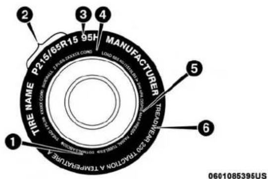
text_image
2 3 4 P215/65R15 95H MANUFACTURER LOAD MAX. ACTIVATED TIRE NAME TREEMEN 20 TRACTON A TEMPERATURE 1 6 0601085395USTireMarkings
1 — U.S. DOT Safety 4 — Maximum Load
Standards Code (TIN)
2 — Size Designation 5 — Maximum Pressure
3 — Service Description 6 — Treadwear, Traction
and Temperature Grades
NOTE:
- P (Passenger) — Metric tire sizing is based on U.S. design standards. P-Metric tires have the letter "P" molded into the sidewall preceding the size designation. Example: P215/65R15 95H.
- European — Metric tire sizing is based on European design standards. Tires designed to this standard have the tire size molded into the sidewall beginning with the section width. The letter "P" is absent from this tire size designation. Example: 215/65R15 96H.
-
LT (Light Truck) — Metric tire sizing is based on U.S. design standards. The size designation for LT-Metric tires is the same as for P-Metric tires except for the letters "LT" that are molded into the sidewall preceding the size designation. Example: LT235/85R16.
-
Temporary spare tires are designed for temporary emergency use only. Temporary high pressure compact spare tires have the letter "T" or "S" molded into the sidewall preceding the size designation. Example: T145/80D18 103M.
- High flotation tire sizing is based on U.S. design standards and it begins with the tire diameter molded into the sidewall. Example: 31x10.5 R15 LT.
398 SERVICING AND MAINTENANCE
TireSizingChart
EXAMPLE:
| ExampleSizeDesignation:P215/65R15XL95H,215/65R1596H,LT235/85R16C,T145/80D18103M,31x10.5R15LT |
| P= Passenger car tire size based on U.S. design standards, or"....blank...." = Passenger car tire based on European design standards, orLT= Light truck tire based on U.S. design standards, orT o r S = Temporary spare tire or31= Overall diameter in inches (in) |
| 215,235,145= Section width in millimeters (mm) |
| 65,85,80= Aspect ratio in percent (%)– Ratio of section height to section width of tire, or10.5= Section width in inches (in) |
| R= Construction code– "R"means radial construction, or– "D"means diagonal or bias construction |
15,16,18= Rim diameter in inches (in)
EXAMPLE:
ServiceDescription:
95= Load Index
- A numerical code associated with the maximum load a tire can carry
H= Speed Symbol
- A symbol indicating the range of speeds at which a tire can carry a load corresponding to its load index under certain operating conditions
- The maximum speed corresponding to the speed symbol should only be achieved under specified operating conditions (i.e., tire pressure, vehicle loading, road conditions, and posted speed limits)
LoadIdentification:
Absence of the following load identification symbols on the sidewall of the tire indicates a Standard Load (SL) tire:
- XL= Extra load (or reinforced) tire, or
- LL = Light load tire or
- C, D, E, F, G = Load range associated with the maximum load a tire can carry at a specified pressure
MaximumLoad– Maximum load indicates the maximum load this tire is designed to carry
Maximum Pressure - Maximum pressure indicates the maximum permissible cold tire inflation pressure for this tire
400 SERVICING AND MAINTENANCE
TireIdentificationNumber(TIN)
The TIN may be found on one or both sides of the tire; however, the date code may only be on one side. Tires with white sidewalls will have the full TIN, including the date code, located on the white sidewall side of the tire. Look for
the TIN on the outboard side of black sidewall tires as mounted on the vehicle. If the TIN is not found on the outboard side, then you will find it on the inboard side of the tire.
| EXAMPLE: |
| DOT MA L9 ABCD 0301 |
| DOT= Department of Transportation- This symbol certifies that the tire is in compliance with the U.S. Department of Transportation tire safety standards and is approved for highway use |
| MA= Code representing the tire manufacturing location (two digits) |
| L9= Code representing the tire size (two digits) |
| ABCD= Code used by the tire manufacturer (one to four digits) |
| 03= Number representing the week in which the tire was manufactured (two digits)- 03 means the 3rd week |
| 01= Number representing the year in which the tire was manufactured (two digits)- 01 means the year 2001- Prior to July 2000, tire manufacturers were only required to have one number to represent the year in which the tire was manufactured. Example: 031 could represent the 3rd week of 1981 or 1991 |
TireTerminologyAndDefinitions
| TermDefinition | |
| B-PillarThe vehicle B-Pillar is the structural member of the body located behind the front door. | |
| Cold Tire Inflation Pressure | Cold tire inflation pressure is defined as the tire pressure after the vehicle has not been driven for at least three hours, or driven less than 1 mile (1.6 km) after sitting for a minimum of three hours. Inflation pressure is measured in units of PSI (pounds per square inch) or kPa (kilopascals). |
| MaximumInflationPressureThe maximum inflation pressure is the maximum permissible cold tire inflation pressure for this tire. The maximum inflation pressure is molded into the sidewall. | |
| Recommended Cold Tire Inflation Pressure | Vehicle manufacturer's recommended cold tire inflation pressure as shown on the tire placard. |
| TirePlacardA label permanently attached to the vehicle describing the vehicle's loading capacity, the original equipment tire sizes and the recommended cold tire inflation pressures. | |
402 SERVICING AND MAINTENANCE
TireLoadingAndTirePressure
NOTE: The proper cold tire inflation pressure is listed on the driver's side B-Pillar or the rear edge of the driver's side door.
Check the inflation pressure of each tire, including the spare tire (if equipped), at least monthly and inflate to the recommended pressure for your vehicle.

text_image
0806115150USExampleTirePlacardLocation(Door)
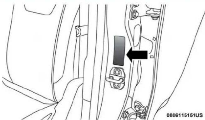
natural_image
Technical line drawing of a car door panel with a black arrow pointing to a component (no text or symbols present)ExampleTirePlacardLocation(B-Pillar)
TireAndLoadingInformationPlacard
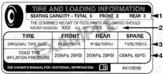
text_image
TIRE AND LOADING INFORMATION SEATING CAPACITY - TOTAL 5 FRONT 2 REAR 3 THE COMBINED WEIGHT OF OCCUPANTS AND CARGO SHOULD NEVER EXCEED XXX KG QF XXX LGS. TIRE FRONT REAR SPARE ORIGINAL TIRE SIZE P195/70R14 P195/70R14 T125/70D15 COLD TIRE INFLATION PRESSURE 200kPa, 29PSI 200kPa, 29PSI 420kPa, 60PSI SEE OWNER'S MANUAL FOR ADDITIONAL INFORMATION 4N109268811b5a9a
TireAndLoadingInformationPlacard
This placard tells you important information about the:
- Number of people that can be carried in the vehicle.
- Total weight your vehicle can carry.
- Tire size designed for your vehicle.
- Cold tire inflation pressures for the front, rear, and spare tires.
Loading
The vehicle maximum load on the tire must not exceed the load carrying capacity of the tire on your vehicle. You will not exceed the tire's load carrying capacity if you adhere to the loading conditions, tire size, and cold tire inflation pressures specified on the Tire and Loading Information placard in "Vehicle Loading" in the "Starting And Operating" section of this manual.
NOTE: Under a maximum loaded vehicle condition, gross axle weight ratings (GAWRs) for the front and rear axles must not be exceeded.
For further information on GAWRs, vehicle loading, and trailer towing, refer to "Vehicle Loading" in the "Starting And Operating" section of this manual.
To determine the maximum loading conditions of your vehicle, locate the statement "The combined weight of occupants and cargo should never exceed XXX kg or XXX lbs" on the Tire and Loading Information placard. The combined weight of occupants, cargo/luggage and trailer tongue weight (if applicable) should never exceed the weight referenced here.
404 SERVICING AND MAINTENANCE
StepsForDeterminingCorrectLoadLimit—
(1) Locate the statement "The combined weight of occupants and cargo should never exceed XXX kg or XXX lbs." on your vehicle's placard.
(2) Determine the combined weight of the driver and passengers that will be riding in your vehicle.
(3) Subtract the combined weight of the driver and passengers from XXX kg or XXX lbs.
(4) The resulting figure equals the available amount of cargo and luggage load capacity. For example, if "XXX" amount equals 1400 lbs. and there will be five 150 lb passengers in your vehicle, the amount of available cargo and luggage load capacity is 650 lbs. (1400-750 (5x150) = 650 lbs.)
(5) Determine the combined weight of luggage and cargo being loaded on the vehicle. That weight may not safely exceed the available cargo and luggage load capacity calculated in Step 4.
(6) If your vehicle will be towing a trailer, load from your trailer will be transferred to your vehicle. Consult this manual to determine how this reduces the available cargo and luggage load capacity of your vehicle.
MetricExampleForLoadLimit
For example, if "XXX" amount equals 635 kg and there will be five 68 kg passengers in your vehicle, the amount of available cargo and luggage load capacity is 295 kg (635-340 (5x68) = 295 kg) as shown in step 4.
NOTE:
- If your vehicle will be towing a trailer, load from your trailer will be transferred to your vehicle. The following table shows examples on how to calculate total load, cargo/luggage, and towing capacities of your vehicle with varying seating configurations and number and size of occupants. This table is for illustration purposes only and may not be accurate for the seating and load carry capacity of your vehicle.
- For the following example, the combined weight of occupants and cargo should never exceed 865 lbs (392 kg).

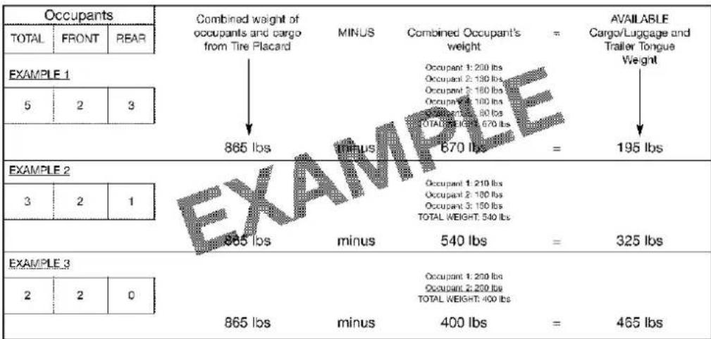
text_image
Occupants TOTAL FRONT REAR EXAMPLE 1 5 2 3 865 lbs MINUS MINUS 670 lbs = AVAILABLE Cargv/Luggage and Trailer Tongue Weight EXAMPLE 2 3 2 1 865 lbs minus Occupant 1: 200 lbs Occupant 2: 190 lbs Occupant 3: 180 lbs Occupant 4: 100 lbs TOTAL WEIGHT: 80 lbs TOTAL WEIGHT: 670 lbs = 195 lbs EXAMPLE 3 2 2 0 865 lbs minus Occupant 1: 200 lbs Occupant 2: 200 lbs TOTAL WEIGHT: 400 lbs = 465 lbsB11add11
WARNING!
Overloadingofyourtiresisdangerous. Overloading cancausetirefailure, affectvehiclehandling, and increaseyourstoppingdistance. Usetiresoftherecommendedloadcapacityforyourvehicle. Neveroverloadthem.

406 SERVICING AND MAINTENANCE
Tires — General Information
TirePressure
Proper tire inflation pressure is essential to the safe and satisfactory operation of your vehicle. Four primary areas are affected by improper tire pressure:
•Safety and Vehicle Stability
• Economy
•Tread Wear
- Ride Comfort
Safety
WARNING!
- Improperlyinflatedtiresaredangerousandcan causecollisions.
- Underinflationincreasestireflexingandcanresult inoverheatingandtirefailure.
• Overinflationreducesatire'sabilitytocushion shock. Objectsontheroadandchuckholescancause damagethatresultintirefailure.
WARNING!(Continued)
• Overinflatedorunderinflatedtirescanaffectvehicle handlingandcanfailsuddenly,resultinginlossof vehiclecontrol.
- Unequal tire pressures can cause steering problems. You could close to control your vehicle.
- Unequaltirepressuresfromonesideofthevehicle totheothercancausethevehicletodrifttotheright orleft.
- Alwaysdrivewitheachtireinflatedtotherecommendedcoldtireinflationpressure.
Both under-inflation and over-inflation affect the stability of the vehicle and can produce a feeling of sluggish response or over responsiveness in the steering.
NOTE:
- Unequal tire pressures from side to side may cause erratic and unpredictable steering response.
- Unequal tire pressure from side to side may cause the vehicle to drift left or right.
FuelEconomy
Underinflated tires will increase tire rolling resistance resulting in higher fuel consumption.
TreadWear
Improper cold tire inflation pressures can cause abnormal wear patterns and reduced tread life, resulting in the need for earlier tire replacement.
RideComfortAndVehicleStability
Proper tire inflation contributes to a comfortable ride. Over-inflation produces a jarring and uncomfortable ride.
TireInflationPressures
The proper cold tire inflation pressure is listed on the driver's side B-Pillar or rear edge of the driver's side door.
At least once a month:
- Check and adjust tire pressure with a good quality pocket-type pressure gauge. Do not make a visual judgement when determining proper inflation. Tires may look properly inflated even when they are underinflated.
- Inspect tires for signs of tire wear or visible damage.
CAUTION!
Afterinspectingoradjustingthetirepressure,always reinstallthevalvestemcap.Thiswillpreventmoisture anddirtfromenteringthevalvestem,whichcould damagethevalvestem.
Inflation pressures specified on the placard are always “cold tire inflation pressure”. Cold tire inflation pressure is defined as the tire pressure after the vehicle has not been driven for at least three hours, or driven less than 1 mile (1.6 km) after sitting for a minimum of three hours. The cold tire inflation pressure must not exceed the maximum inflation pressure molded into the tire sidewall.
Check tire pressures more often if subject to a wide range of outdoor temperatures, as tire pressures vary with temperature changes.
Tire pressures change by approximately 1 psi (7 kPa) per 12^ F ( 7^ C) of air temperature change. Keep this in mind when checking tire pressure inside a garage, especially in the Winter.
Example: If garage temperature = 68^ F ( 20^ C) and the outside temperature = 32^ F ( 0^ C) then the cold tire inflation pressure should be increased by 3 psi (21 kPa), which equals 1 psi (7 kPa) for every 12^ F ( 7^ C) for this outside temperature condition.

Tire pressure may increase from 2 to 6 psi (13 to 40 kPa) during operation. DO NOT reduce this normal pressure build up or your tire pressure will be too low.
TirePressuresForHighSpeedOperation
The manufacturer advocates driving at safe speeds and within posted speed limits. Where speed limits or conditions are such that the vehicle can be driven at high speeds, maintaining correct tire inflation pressure is very important. Increased tire pressure and reduced vehicle loading may be required for high-speed vehicle operation. Refer to an authorized tire dealer or original equipment vehicle dealer for recommended safe operating speeds, loading and cold tire inflation pressures.
WARNING!
Highspeeddrivingwithyourvehicleundermaximum loadisdangerous.Theaddedstrainonyourtirescould causethemtofail.Youcouldhaveaseriouscollision. Donotdrivevehicleloadedtothemaximumcapacity atcontinuousspeedsabove75mph(120km/h).
RadialPlyTires
WARNING!
Combiningradialplytireswithothertypesoftireson yourvehiclewillcauseyourvehicletohandlepoorly. Theinstabilitycouldcauseacollision.Alwaysuse radialplytiresinsetsoffour.Nevercombinethem withothertypesoftires.
TireRepair
If your tire becomes damaged, it may be repaired if it meets the following criteria:
- The tire has not been driven on when flat.
- The damage is only on the tread section of your tire (sidewall damage is not repairable).
- The puncture is no greater than a 14 of an inch (6 mm).
Consult an authorized tire dealer for tire repairs and additional information.
Damaged Run Flat tires, or Run Flat tires that have experienced a loss of pressure should be replaced immediately with another Run Flat tire of identical size and service description (Load Index and Speed Symbol).

RunFlatTires—IfEquipped
Run Flat tires allow you the capability to drive 50 miles (80 km) at 50 mph (80 km/h) after a rapid loss of inflation pressure. This rapid loss of inflation is referred to as the Run Flat mode. A Run Flat mode occurs when the tire inflation pressure is of/or below 14 psi (96 kPa). Once a Run Flat tire reaches the run flat mode it has limited driving capabilities and needs to be replaced immediately. A Run Flat tire is not repairable.
It is not recommended driving a vehicle loaded at full capacity or to tow a trailer while a tire is in the run flat mode.
See the tire pressure monitoring section for more information.
TireSpinning
When stuck in mud, sand, snow, or ice conditions, do not spin your vehicle's wheels above 30 mph (48 km/h) or for longer than 30 seconds continuously without stopping.
Refer to "Freeing A Stuck Vehicle" in "In Case Of Emergency" in your Owner's Manual for further information.
WARNING!
Fastspinningtirescanbedangerous. Forces generated by excessive wheels speeds may cause it to damage or failure. Atire could explode and injuresome one. Do not spiny our vehicle's wheels faster than 30 mph (48 km/h) form more than 30 seconds continuously when you are stuck, and donotlet any on e a r aspinning wheel, nomatter what the speed.
TreadWearIndicators
Tread wear indicators are in the original equipment tires to help you in determining when your tires should be replaced.
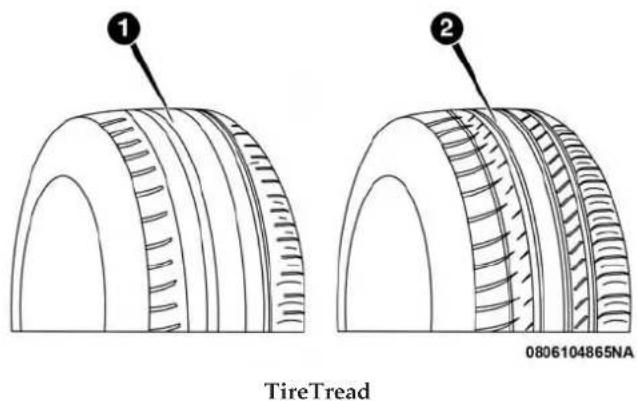
1—WornTire
2—New Tire
These indicators are molded into the bottom of the tread grooves. They will appear as bands when the tread depth becomes a 1/16 of an inch (1.6 mm). When the tread is worn to the tread wear indicators, the tire should be replaced. Refer to "Replacement Tires" in this section for further information.
LifeOfTire
The service life of a tire is dependent upon varying factors including, but not limited to:
- Driving style.
- Tire pressure - Improper cold tire inflation pressures can cause uneven wear patterns to develop across the tire tread. These abnormal wear patterns will reduce tread life, resulting in the need for earlier tire replacement.
•Distance driven.
- Performance tires, tires with a speed rating of V or higher, and Summer tires typically have a reduced tread life. Rotation of these tires per the vehicle scheduled maintenance is highly recommended.
WARNING!
Tiresandthesparetireshouldbereplacedaftersix years,regardlessoftheremainingtread.Failureto followthiswarningcanresultinsuddentirefailure. Youcouldlosecontrolandhaveacollisionresultingin seriousinjuryordeath.
Keep dismounted tires in a cool, dry place with as little exposure to light as possible. Protect tires from contact with oil, grease, and gasoline.
ReplacementTires
The tires on your new vehicle provide a balance of many characteristics. They should be inspected regularly for wear and correct cold tire inflation pressures. The manufacturer strongly recommends that you use tires equivalent to the originals in size, quality and performance when replacement is needed. Refer to the paragraph on "Tread Wear Indicators" in this section. Refer to the Tire and Loading Information placard or the Vehicle Certification Label for the size designation of your tire. The Load Index and Speed Symbol for your tire will be found on the original equipment tire sidewall.
See the Tire Sizing Chart example found in the "Tire Safety Information" section of this manual for more information relating to the Load Index and Speed Symbol of a tire. It is recommended to replace the two front tires or two rear tires as a pair. Replacing just one tire can seriously affect your vehicle's handling. If you ever replace a wheel, make sure that the wheel's specifications match those of the original wheels.
It is recommended you contact an authorized tire dealer or original equipment dealer with any questions you may have on tire specifications or capability. Failure to use equivalent replacement tires may adversely affect the safety, handling, and ride of your vehicle.
WARNING!
- Donotuseatire, wheelsize, loadrating, orspeed rating other than that specified for your vehicle. Some combinations of unapproved tires and wheels may change suspension dimensions and performance characteristics, resulting in changest steering, handling, and braking of your vehicle. This can cause unpredictable handling and stress steering and suspension components. You could lose control and have a collision resulting in serious injury or death. Use only the tire and wheels sizes with load ratings approved for your vehicle.
(Continued)

WARNING!(Continued)
- Neveruseatirewithasmallerloadindexorcapacity, otherthanwhatwasoriginallyequippedonyour vehicle. Using atirewithasmallerloadindexcould resultintireoverloadingandfailure. You could lose control and have acollision.
- Failuretoequipyourvehiclewithtireshavingadequatespeedcapabilitycanresultinsuddentirefailureandlossofvehiclecontrol.
CAUTION!
Replacingoriginaltireswithtiresofadifferentsizemay resultinfalsespeedometerandodometerreadings.
Tire Types
AllSeasonTires—IfEquipped
All Season tires provide traction for all seasons (Spring, Summer, Fall, and Winter). Traction levels may vary between different all season tires. All season tires can be identified by the M+S, M&S, M/S or MS designation on the tire sidewall. Use all season tires only in sets of four; failure to do so may adversely affect the safety and handling of your vehicle.
SummerOrThreeSeasonTires—IfEquipped
Summer tires provide traction in both wet and dry conditions, and are not intended to be driven in snow or on ice. If your vehicle is equipped with Summer tires, be aware these tires are not designed for Winter or cold driving conditions. Install Winter tires on your vehicle when ambient temperatures are less than 40^ F ( 5^ C) or if roads are covered with ice or snow. For more information, contact an authorized dealer.
Summer tires do not contain the all season designation or mountain/snowflake symbol on the tire sidewall. Use Summer tires only in sets of four; failure to do so may adversely affect the safety and handling of your vehicle.
WARNING!
DonotuseSummertiresinsnow/iceconditions. You could lose vehicle control, resulting in severe injury or death. Driving to fast for conditions also creates the possibility of loss of vehicle control.
SnowTires
Some areas of the country require the use of snow tires during the Winter. Snow tires can be identified by a “mountain/snowflake” symbol on the tire sidewall.
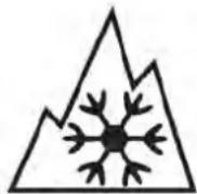
If you need snow tires, select tires equivalent in size and type to the original equipment tires. Use snow tires only in sets of four; failure to do so may adversely affect the safety and handling of your vehicle.
Snow tires generally have lower speed ratings than what was originally equipped with your vehicle and should not be operated at sustained speeds over 75 mph (120 km/h). For speeds above 75 mph (120 km/h) refer to original equipment or an authorized tire dealer for recommended safe operating speeds, loading and cold tire inflation pressures.
While studded tires improve performance on ice, skid and traction capability on wet or dry surfaces may be poorer than that of non-studded tires. Some states prohibit studded tires; therefore, local laws should be checked before using these tire types.
Spare Tires — If Equipped
NOTE: For vehicles equipped with Tire Service Kit instead of a spare tire, please refer to "Tire Service Kit" in "In Case Of Emergency" for further information.
CAUTION!
Because of the reduced ground clearance, donottake your vehicle through an automatic car wash with a compactor limited usetemporary spare installed. Damageto the vehicle may result.
SpareTireMatchingOriginalEquippedTireAndWheel—IfEquipped
Your vehicle may be equipped with a spare tire and wheel equivalent in look and function to the original equipment tire and wheel found on the front or rear axle of your vehicle. This spare tire may be used in the tire rotation for your vehicle. If your vehicle has this option, refer to an authorized tire dealer for the recommended tire rotation pattern.
414 SERVICING AND MAINTENANCE
CompactSpareTire—IfEquipped
The compact spare is for temporary emergency use only. You can identify if your vehicle is equipped with a compact spare by looking at the spare tire description on the Tire and Loading Information Placard located on the driver's side door opening or on the sidewall of the tire. Compact spare tire descriptions begin with the letter "T" or "S" preceding the size designation. Example: T145/80D18 103M.
T, S = Temporary Spare Tire
Since this tire has limited tread life, the original equipment tire should be repaired (or replaced) and reinstalled on your vehicle at the first opportunity.
Do not install a wheel cover or attempt to mount a conventional tire on the compact spare wheel, since the wheel is designed specifically for the compact spare tire. Do not install more than one compact spare tire and wheel on the vehicle at any given time.
WARNING!
Compactandcollapsiblesparesarefortemporary emergencyuseonly.Withthesespares,donotdrive morethan50mph(80km/h).Temporaryusespares havelimitedtreadlife.Whenthetreadisworntothe treadwearindicators,thetemporaryusesparetire needstobereplaced.Besuretofollowthewarnings, which apply to your spare. Failure to do so could result insparetirefailureandlossofvehiclecontrol.
CollapsibleSpareTire—IfEquipped
The collapsible spare is for temporary emergency use only. You can identify if your vehicle is equipped with a collapsible spare by looking at the spare tire description on the Tire and Loading Information Placard located on the driver's side door opening or on the sidewall of the tire.
Collapsible spare tire description example: 165/80-17 101P.
Since this tire has limited tread life, the original equipment tire should be repaired (or replaced) and reinstalled on your vehicle at the first opportunity.
Inflate collapsible tire only after the wheel is properly installed to the vehicle. Inflate the collapsible tire using the electric air pump before lowering the vehicle.

Do not install a wheel cover or attempt to mount a conventional tire on the collapsible spare wheel, since the wheel is designed specifically for the collapsible spare tire.
WARNING!
CompactandCollapsiblesparesarefortemporary emergencyuseonly.Withthesespares,donotdrive morethan50mph(80km/h).Temporaryusespares havelimitedtreadlife.Whenthetreadisworntothe treadwearindicators,thetemporaryusesparetire needstobereplaced.Besuretofollowthewarnings, whichapplytoyourspare.Failureretodosocouldresult insparetirefailureandlossofvehiclecontrol.
FullSizeSpare—IfEquipped
The full size spare is for temporary emergency use only. This tire may look like the originally equipped tire on the front or rear axle of your vehicle, but it is not. This spare tire may have limited tread life. When the tread is worn to the tread wear indicators, the temporary use full size spare tire needs to be replaced. Since it is not the same as your original equipment tire, replace (or repair) the original equipment tire and reinstall on the vehicle at the first opportunity.
LimitedUseSpare—IfEquipped
The limited use spare tire is for temporary emergency use only. This tire is identified by a label located on the limited use spare wheel. This label contains the driving limitations for this spare. This tire may look like the original equipped tire on the front or rear axle of your vehicle, but it is not. Installation of this limited use spare tire affects vehicle handling. Since it is not the same as your original equipment tire, replace (or repair) the original equipment tire and reinstall on the vehicle at the first opportunity.
WARNING!
Limitedusesparesareforemergencyuseonly.Installationofthislimitedusesparetireaffectsvehicle handling.Withthistire,donotdrivemorethanthe speedlistedonthelimitedusesparewheel.Keep inflatedtothecoldtireinflationpressureslistedon yourTireandLoadingInformationPlacardlocatedon thedriver'ssideB-Pillarortherearedgeofthedriver's sidedoor.Replace(orrepair)theoriginalequipment tireatthefirstopportunityandreinstallitonyour vehicle.Failureretodosocouldresultinlossofvehicle control.

Wheel And Wheel Trim Care
All wheels and wheel trim, especially aluminum and chrome plated wheels, should be cleaned regularly using mild (neutral Ph) soap and water to maintain their luster and to prevent corrosion. Wash wheels with the same soap solution recommended for the body of the vehicle and remember to always wash when the surfaces are not hot to the touch.
Your wheels are susceptible to deterioration caused by salt, sodium chloride, magnesium chloride, calcium chloride, etc., and other road chemicals used to melt ice or control dust on dirt roads. Use a soft cloth or sponge and mild soap to wipe away promptly. Do not use harsh chemicals or a stiff brush. They can damage the wheel's protective coating that helps keep them from corroding and tarnishing.
CAUTION!
Avoidproductsorautomaticcarwashesthatuseacidic solutionsorstrongalkalineadditivesorharshbrushes. Manyaftermarketwheelcleanersandautomaticcar washesmaydamagethewheel'sprotectivefinish. SuchdamageisnotcoveredbytheNewVehicle LimitedWarranty.Onlycarwashsoap,MoparWheel Cleanerorequivalentisrecommended.
When cleaning extremely dirty wheels including excessive brake dust, care must be taken in the selection of tire and wheel cleaning chemicals and equipment to prevent damage to the wheels. Mopar Wheel Treatment or Mopar Chrome Cleaner or their equivalent is recommended or select a non-abrasive, non-acidic cleaner for aluminum or chrome wheels.
CAUTION!
Donotusescouringpads,steelwool,abristlebrush, metalpolishesorovencleaner. These products may damage the wheel's protective finish. Such damage is not covered by the New Vehicle Limited Warranty. Only car wash soap, Mopar Wheel Cleaner or equivalent is recommended.
NOTE: If you intend parking or storing your vehicle for an extended period after cleaning the wheels with wheel cleaner, drive your vehicle and apply the brakes to remove the water droplets from the brake components. This activity will remove the red rust on the brake rotors and prevent vehicle vibration when braking.
DarkVaporChrome, BlackSatinChrome, or LowGloss ClearCoatWheels
| CAUTION! |
| Ifyourvehicleisequippedwiththesespecialty wheels,DONOTUSEwheelcleaners,abrasives,or polishingcompounds.Theywillpermanentlydamage thisfinishandsuchdamageisnotcoveredbytheNew VehicleLimitedWarranty.HANDWASHONLYUS-INGMILDSOAPANDWATERWITHASOFT CLOTH.Usedonaregularbasis;thisisallthatis requiredtomaintainthisfinish. |
Tire Chains (Traction Devices)
Use of traction devices require sufficient tire-to-body clearance. Follow these recommendations to guard against damage.
- Traction device must be of proper size for the tire, as recommended by the traction device manufacturer.
Please follow the table below for proper tire size, chain type, and axle recommendations:
| VehicleAxleRecommendationsTireSizesChainClass | |||
| Chassis Cab 3500 (Single Rear Wheel) Models | Rear Only | LT275/70R18E | U Class |
| Chassis Cab 3500 (Dual Rear Wheel) 4X2 Models | Rear Only | LT235/80R17E | U Class |
| Chassis Cab 3500 (Dual Rear Wheel) 4X4 Models | Front/Rear | LT235/80R17E | U Class |
| Chassis Cab 4500/5500 Models | Rear Only | 225/70R19.5G | U Class |
WARNING!
Using tires of different size and type (M+S, Snow) between front and rear axles can cause unpredictable handling. You could lose control and have a collision.
CAUTION!
To avoid damagetoyourvehicleortires, observethe following precautions:
- Because of restricted traction device clearance between tires and others suspension components, it is important that only traction devices being good condition are used. Brokendevices can cause serious damage. Stop the vehicle immediately if noise occurs that could indicate device breakage. Remove the damaged part of the device before further use.
- Installdeviceastightlyaspossibleandthenre-tightenafterdrivingabout 12 mile(0.8km).
- Donotexceed30mph(48km/h).
- Drivecautiously and avoid severe returns and large bumps, especially with loaded vehicle.
- Donotdriveforaprolongedperiodondrypavement.
CAUTION!(Continued)
- Observethetractiondevicemanufacturer'sinstruc-tionsonthemethodofinstallation,operatingspeed, andconditionsforuse.Alwaysusethesuggested operatingspeedofthedevicemanufacturer'sifitis lessthan30mph(48km/h).
- Donotusetractiondevicesonacompactsparetire.
Tire Rotation Recommendations
Tires on the front and rear axles of vehicles operate at different loads and perform different steering, driving, and braking functions. For these reasons, they wear at unequal rates.
These effects can be reduced by timely rotation of tires. The benefits of rotation are especially worthwhile with aggressive tread designs such as those on On/Off Road type tires. Rotation will increase tread life, help to maintain mud, snow, and wet traction levels, and contribute to a smooth, quiet ride.
Refer to the "Maintenance Plan" for the proper maintenance intervals. More frequent rotation is permissible if desired. The reasons for any rapid or unusual wear should be corrected prior to rotation being performed.
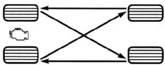
flowchart
graph TD
    A["Vehicle Icon"] --> B["Left Vehicle"]
    A --> C["Right Vehicle"]
    B --> D["Left Vehicle"]
    B --> E["Right Vehicle"]
    C --> F["Left Vehicle"]
    C --> G["Right Vehicle"]
055703771
TireRotation
NOTE: On Canadian vehicles only, if your vehicle is equipped with All-Season type tires on the front and On/Off Road type tires mounted on the rear, do not use a front to back rotation pattern. Instead, rotate your tires side to side at the recommended intervals.
DualRearWheels
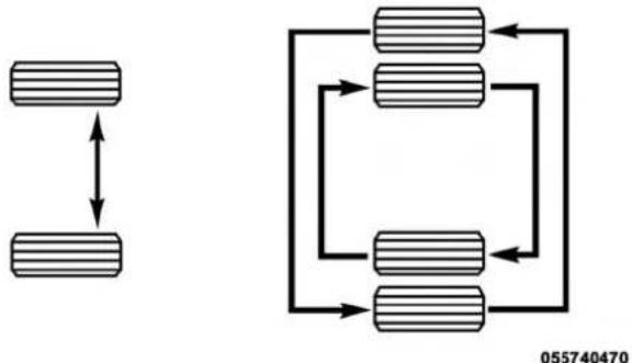
flowchart
graph TD
    A["Top Block"] <--> B["Bottom Block"]
    C["Top Block"] --> D["Bottom Block"]
    D --> E["Bottom Block"]
    E --> F["Bottom Block"]
    F --> G["Bottom Block"]
    G --> H["Bottom Block"]
    H --> I["Bottom Block"]
    I --> J["Bottom Block"]
    J --> K["Bottom Block"]
    K --> L["Bottom Block"]
    L --> M["Bottom Block"]
    M --> N["Bottom Block"]
    N --> O["Bottom Block"]
    O --> P["Bottom Block"]
    P --> Q["Bottom Block"]
    Q --> R["Bottom Block"]
    R --> S["Bottom Block"]
    S --> T["Bottom Block"]
    T --> U["Bottom Block"]
    U --> V["Bottom Block"]
    V --> W["Bottom Block"]
    W --> X["Bottom Block"]
    X --> Y["Bottom Block"]
    Y --> Z["Bottom Block"]
    Z --> AA["Bottom Block"]
    AA --> AB["Bottom Block"]
    AB --> AC["Bottom Block"]
    AC --> AD["Bottom Block"]
    AD --> AE["Bottom Block"]
    AE --> AF["Bottom Block"]
    AF --> AG["Bottom Block"]
    AG --> AH["Bottom Block"]
TireRotation
The tires used on dual wheel assemblies should be matched for wear to prevent overloading one tire in a set. To check if tires are even, lay a straight edge across all four tires. The straight edge should touch all the tires.
NOTE: If your vehicle is equipped with a Tire Pressure Information System (TPIS):
- The Tire Pressure Information System (TPIS) uses unique sensors in the inner rear wheels to help identify them from the outer rear wheels, because of this, the inner and outer wheel locations can't be switched.

420 SERVICING AND MAINTENANCE
- After a tire rotation is completed, as shown below, the system can auto learn the locations of each sensor ID. Auto learning/localization occurs when the vehicle ignition status is changed from Off to On and speeds of greater than 5 mph (8km/h) are obtained and remain over 5mph (8km/h) for at about a 15 minute period. You may need to drive for 20 minutes to account slower speeds and stops.
- If the tires are rotated incorrectly, the Auto localization of the TPIS sensors will fail to locate correctly resulting in incorrect locations for the pressure values displayed in the Instrument Cluster.
CAUTION!
- 4500/5500DualRearTiresmayonlyhaveoneapproveddirectionofrotation.Thisistoaccommodate theasymmetricaldesign(treadpattern)oftheOn/Offroadtire.
(Continued)
CAUTION!(Continued)
- Whenreplacingaflat,thesparetiremayhavetobe remountedontherimorinstalledatadifferent locationtomaintainthecorrectplacementofthetire onthewheelrelativetothetire/wheelpositionon thevehicle.Forexample,ifthespareisusedto replaceanouterreartireitwillhavetoberemounted ontherimsothatthewheelisdishedinward.That waythetreaddesignofasymmetricaltireswill maintainproperposition.
DEPARTMENT OF TRANSPORTATION UNIFORM TIRE QUALITY GRADES
The following tire grading categories were established by the National Highway Traffic Safety Administration. The specific grade rating assigned by the tire's manufacturer in each category is shown on the sidewall of the tires on your vehicle.
All passenger vehicle tires must conform to Federal safety requirements in addition to these grades.
Treadwear
The Treadwear grade is a comparative rating, based on the wear rate of the tire when tested under controlled conditions on a specified government test course. For example, a tire graded 150 would wear one and one-half times as well on the government course as a tire graded 100. The relative performance of tires depends upon the actual conditions of their use, however, and may depart significantly from the norm due to variations in driving habits, service practices, and differences in road characteristics and climate.
Traction Grades
The Traction grades, from highest to lowest, are AA, A, B, and C. These grades represent the tire's ability to stop on wet pavement, as measured under controlled conditions on specified government test surfaces of asphalt and concrete. A tire marked C may have poor traction performance.
WARNING!
Thetractiongradeassignedtothistireisbasedon straight-aheadbrakingtractiontests, and does not include acceleration, cornering, hydroplaning, or peaktraction characteristics.
Temperature Grades
The Temperature grades are A (the highest), B, and C, representing the tire's resistance to the generation of heat and its ability to dissipate heat, when tested under controlled conditions on a specified indoor laboratory test wheel.
Sustained high temperature can cause the material of the tire to degenerate and reduce tire life, and excessive temperature can lead to sudden tire failure. The grade C corresponds to a level of performance, which all passenger vehicle tires must meet under the Federal Motor Vehicle Safety Standard No. 109. Grades B and A represent higher levels of performance on the laboratory test wheel, than the minimum required by law.
WARNING!
Thetemperaturegradeforthistireisestablished for atirethatisproperlyinflatedandnotoverloaded. Excessivespeed,under-inflation,orexcessiveloading,eitherseparatelyorincombination,cancause heatbuildupandpossibletirefailure.
STORING THE VEHICLE
If you are storing your vehicle for more than 21 days, we recommend that you take the following steps to minimize the drain on your vehicle's battery:
- Disconnect the negative cable from battery.
- Any time you store your vehicle or keep it out of service (i.e., vacation) for two weeks or more, run the air conditioning system at idle for about five minutes in the fresh air and high blower setting. This will ensure adequate system lubrication to minimize the possibility of compressor damage when the system is started again.
BODYWORK
Protection From Atmospheric Agents
Vehicle body care requirements vary according to geographic locations and usage. Chemicals that make roads passable in snow and ice and those that are sprayed on trees and road surfaces during other seasons are highly corrosive to the metal in your vehicle. Outside parking, which exposes your vehicle to airborne contaminants, road surfaces on which the vehicle is operated, extreme hot or cold weather and other extreme conditions will have an adverse effect on paint, metal trim, and underbody protection.
The following maintenance recommendations will enable you to obtain maximum benefit from the corrosion resistance built into your vehicle.
WhatCausesCorrosion?
Corrosion is the result of deterioration or removal of paint and protective coatings from your vehicle.
The most common causes are:
- Road salt, dirt and moisture accumulation.
- Stone and gravel impact.
- Insects, tree sap and tar.
- Salt in the air near seacoast localities.
• Atmospheric fallout/industrial pollutants.
Body And Underbody Maintenance
CleaningHeadlights
Your vehicle is equipped with plastic headlights and fog lights that are lighter and less susceptible to stone breakage than glass headlights.
Plastic is not as scratch resistant as glass and therefore different lens cleaning procedures must be followed.
To minimize the possibility of scratching the lenses and reducing light output, avoid wiping with a dry cloth. To remove road dirt, wash with a mild soap solution followed by rinsing.
Do not use abrasive cleaning components, solvents, steel wool or other aggressive material to clean the lenses.
Preserving The Bodywork
Washing
- Wash your vehicle regularly. Always wash your vehicle in the shade using Mopar Car Wash, or a mild car wash soap, and rinse the panels completely with clear water.
- If insects, tar, or other similar deposits have accumulated on your vehicle, use Mopar Super Kleen Bug and Tar Remover to remove.
- Use a high quality cleaner wax, such as Mopar Cleaner Wax to remove road film, stains and to protect your paint finish. Take care never to scratch the paint.
- Avoid using abrasive compounds and power buffing that may diminish the gloss or thin out the paint finish.
CAUTION!
- Donotuseabrasiveorstrongcleaningmaterialssuch assteelwoolorscouringpowderthatwillscratch metalandpaintedsurfaces.
- Useofpowerwashersexceeding1,200psi(8,274kPa) canresultindamageorremovalofpaintanddecals.
424 SERVICING AND MAINTENANCE
SpecialCare
- If you drive on salted or dusty roads or if you drive near the ocean, hose off the undercarriage at least once a month.
- It is important that the drain holes in the lower edges of the doors, rocker panels, and trunk be kept clear and open.
- If you detect any stone chips or scratches in the paint, touch them up immediately. The cost of such repairs is considered the responsibility of the owner.
- If your vehicle is damaged due to a collision or similar cause that destroys the paint and protective coating, have your vehicle repaired as soon as possible. The cost of such repairs is considered the responsibility of the owner.
- If you carry special cargo such as chemicals, fertilizers, de-icer salt, etc., be sure that such materials are well packaged and sealed.
- If a lot of driving is done on gravel roads, consider mud or stone shields behind each wheel.
- Use Mopar Touch Up Paint on scratches as soon as possible. An authorized dealer has touch up p match the color of your vehicle.
aint to
INTERIORS
Seats And Fabric Parts
Use Mopar Total Clean to clean fabric upholstery and carpeting.
WARNING!
Donotusevolatilesolventsforcleaningpurposes. Manyarepotentiallyflammable,andifusedinclosed areastheymaycauserespiratoryharm.
StainRepelFabricCleaningProcedure—IfEquipped
Stain Repel seats may be cleaned in the following manner:
- Remove as much of the stain as possible by blotting with a clean, dry towel.
- Blot any remaining stain with a clean, damp towel.
- For tough stains, apply Mopar Total Clean, or a mild soap solution to a clean, damp cloth and remove stain. Use a fresh, damp towel to remove soap residue.
- For grease stains, apply Mopar Multi-Purpose Cleaner to a clean, damp cloth and remove stain. Use a fresh, damp towel to remove soap residue.
- Do not use any harsh solvents or any other form of protectants on Stain Repel products.
DEALER ePROCESS
SeatBeltMaintenance
Do not bleach, dye or clean the belts with chemical solvents or abrasive cleaners. This will weaken the fabric. Sun damage can also weaken the fabric.
If the belts need cleaning, use a mild soap solution or lukewarm water. Do not remove the belts from the vehicle to wash them. Dry with a soft cloth.
Replace the belts if they appear frayed or worn or if the buckles do not work properly.
NOTE: If the belts retract slowly, inspect the upper turning loop for soiling. If soiling is present, clean with a wet soft cloth until all residue is removed.
WARNING!
Afrayedortornbeltcouldripapartinacollisionand leaveyouwithnoprotection.Inspectthebeltsystem periodically,checkingforcuts,frays,orlooseparts. Damagedpartsmustbereplacedimmediately.Donot disassembleormodifythesystem.Seatbeltassemblies mustbereplacedafteracollisioniftheyhavebeen damaged(i.e.,bentretractor,tornwebbing,etc.).
Plastic And Coated Parts
Use Mopar Total Clean to clean vinyl upholstery.
CAUTION!
- Directcontactofairfresheners,insectrepellents, suntanlotions,orhandsanitizerstotheplastic, painted,ordecoratedsurfacesoftheinteriormay causepermanentdamage.Wipeawayimmediately.
- Damagecausedbythesetypeofproductsmaynotbe coveredbyyourNewVehicleLimitedWarranty.
CleaningPlasticInstrumentClusterLenses
The lenses in front of the instruments in this vehicle are molded in clear plastic. When cleaning the lenses, care must be taken to avoid scratching the plastic.
- Clean with a wet soft cloth. A mild soap solution may be used, but do not use high alcohol content or abrasive cleaners. If soap is used, wipe clean with a clean damp cloth.
- Dry with a soft cloth.
426 SERVICING AND MAINTENANCE
Leather Parts
Mopar Total Clean is specifically recommended for leather upholstery.
Your leather upholstery can be best preserved by regular cleaning with a damp soft cloth. Small particles of dirt can act as an abrasive and damage the leather upholstery and should be removed promptly with a damp cloth. Stubborn soils can be removed easily with a soft cloth and Mopar Total Clean. Care should be taken to avoid soaking your leather upholstery with any liquid. Please do not use polishes, oils, cleaning fluids, solvents, detergents, or ammonia-based cleaners to clean your leather upholstery. Application of a leather conditioner is not required to maintain the original condition.
NOTE: If equipped with light colored leather, it tends to show any foreign material, dirt, and fabric dye transfer more so than darker colors. The leather is designed for easy cleaning, and FCA recommends Mopar total care leather cleaner applied on a cloth to clean the leather seats as needed.
CAUTION!
DonotuseAlcoholandAlcohol-basedand/orKetone basedcleaningproductstocleanleatherseats,as damagetheseatmayresult.
Glass Surfaces
All glass surfaces should be cleaned on a regular basis with Mopar Glass Cleaner, or any commercial household-type glass cleaner. Never use an abrasive type cleaner. Use caution when cleaning the inside rear window equipped with electric defrosters or windows equipped with radio antennas. Do not use scrapers or other sharp instruments that may scratch the elements.
When cleaning the rear view mirror, spray cleaner on the towel or cloth that you are using. Do not spray cleaner directly on the mirror.
TECHNICAL SPECIFICATIONS
CONTENTS
■IDENTIFICATION DATA. . . . . . . . . . . . . . . . . . . . . . . . . . . . . . . . . . . . . . . . . . . . . 428
□Vehicle Identification Number .....428
□Hydraulic Brake Assist....429
■WHEEL AND TIRE TORQUE SPECIFICATIONS . .429
□Torque Specifications . . . . . . . . . . . . . . . . . . . . . . . . . . . . . . . . . . . . . . . . . . . 429
■FUEL REQUIREMENTS....432
□6.4L Engine . . . . . . . . . . . . . . . . . . . . . . . . . . . . . . . . . . . . . . . . . . . . . . . . . . . . . . . . . . 432
□Reformulated Gasoline....432
□Materials Added To Fuel . . . . . . . . . . . . . . . . . . . . . . . . . . . . . . . . 432
□Gasoline/Oxygenate Blends....433
☐Do Not Use E-85 In Non-Flex Fuel Vehicles . . . 434
□CNG And LP Fuel System Modifications .....434
□MMT In Gasoline. 434
□Fuel System Cautions . . . . . . . . . . . . . . . . . . . . . . . . . . . . . . . . . . . . . . . . . . . . 435
□Carbon Monoxide Warnings .....435
■FLUID CAPACITIES....436
■FLUIDS AND LUBRICANTS....437
□Engine....437
□Chassis....439
428 TECHNICAL SPECIFICATIONS
IDENTIFICATION DATA
Vehicle Identification Number
The Vehicle Identification Number (VIN) is found on the left front corner of the instrument panel, visible through the windshield. This number also appears on the vehicle frame and underbody as well as the Automobile Information Disclosure Label affixed to a window on your vehicle, the vehicle registration and title.
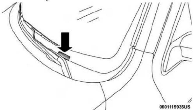
natural_image
Diagram of a car interior showing a handle and seat with an arrow indicating direction (no text or symbols present)VehicleIdentificationNumber
NOTE: It is illegal to remove or alter the VIN.
BRAKE SYSTEM
If power assist is lost for any reason (for example, repeated brake applications with the engine off), the brakes will still function. However, you will experience a substantial increase in braking effort to stop the vehicle.
If either the front or rear hydraulic system loses normal braking capability, the remaining system will still function with some loss of overall braking effectiveness. This will be evident by increased pedal travel during application, greater pedal force required to slow or stop, and activation of the "Brake Warning Light" and the "ABS Warning Light" (if equipped) during brake use.
The brake system power assist is provided by a hydro-boost unit which shares fluid with the power steering system. You may experience some clicking or hissing noises from the hydro-boost system during hard braking conditions.
NOTE: Under cold temperatures, pedal effort will be higher than normal until the power steering fluid reaches operating temperature.

Hydraulic Brake Assist
The brake system power assist is provided by a hydro-boost unit which shares fluid with the power steering system. You may experience some clicking or hissing noises from the hydro-boost system during hard braking conditions.
NOTE: Under cold temperatures, pedal effort will be higher than normal until the power steering fluid reaches operating temperature.
WHEEL AND TIRE TORQUE SPECIFICATIONS
Proper lug nut/bolt torque is very important to ensure that the wheel is properly mounted to the vehicle. Any time a wheel has been removed and reinstalled on the vehicle, the lug nuts/bolts should be torqued using a properly calibrated torque wrench using a high quality six sided (hex) deep wall socket.
Torque Specifications
| LugNut/BoltTorque | LugNut/BoltType | **LugNut/BoltSize | LugNut/BoltSocket Size |
| 120-150 Ft-Lbs (160-200 N·m) | Cone M14 x 1.50 22 mm | ||
| 130-160 Ft-Lbs (190-220 N·m) | Flanged | ||
**Use only your authorized dealer recommended lug nuts/bolts and clean or remove any dirt or oil before tightening.
Inspect the wheel mounting surface prior to mounting the tire and remove any corrosion or loose particles.
NOTE: Dual wheels are flat mounted, center piloted. The lug nuts are a two-piece assembly. When the tires are being rotated or replaced, clean these lug nuts and add two drops of oil at the interface between the hex and the washer. Ensure that the socket is fully engaged on the lug nut/bolt (do not insert it half way).
430 TECHNICAL SPECIFICATIONS
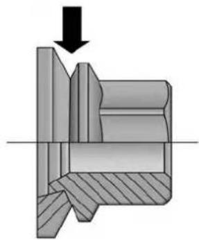
natural_image
Cross-sectional diagram of a mechanical assembly with a downward arrow indicating force or direction (no text or symbols present)0322115841US
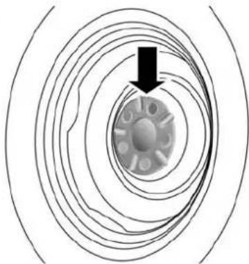
natural_image
Diagram of concentric circular wave patterns with a central particle and arrow, no text or symbols present0605097260US
OilInterfaceLocationWheelMountingSurface
Do not oil wheel studs. For chrome wheels, do not substitute with chrome plated wheel nuts.
Retighten the wheel nuts in the same sequence to the torques listed in the table. Go through the sequence a second time to verify that specific torque has been achieved. Retighten to specifications after 25 miles (40 km) and check the lug nut/bolt torque to be sure that all the lug nuts/bolts are properly seated against the wheel.

chemical
Diagram of 8/10 Lugnuts/BoltsTorquePatterns showing two circular configurations with numbered nodes and plus/minus signs1 — 10 Bolt Pattern
2—8 Bolt Pattern
It is recommended that wheel stud nuts be kept torqued to specifications at all times. Torque wheel stud nuts to specifications at each lubrication interval.
All wheel nuts should be tightened occasionally to eliminate the possibility of wheel studs being sheared or the bolt holes in the wheels becoming elongated. This is especially important during the first few hundred miles/kilometers of operation to allow the wheel nuts to become properly set. All wheel nuts should first be firmly seated against the wheel. The wheel nuts should then be tightened to recommended torque. Tighten the wheel nuts to final torque in increments. Progress around the bolt circle, tightening the wheel nut opposite to the wheel nut just previously tightened until final torque is achieved.
WARNING!
To avoid the riskofforcing the vehicle off the jack, do nottight enthe lugnuts fully until the vehicle has been lowered. Failure to follow this warning may result in personal injury.

432 TECHNICAL SPECIFICATIONS
FUEL REQUIREMENTS
6.4L Engine
Do not use E-85 flex fuel or ethanol blends greater than 15% in this engine.

This engines is designed to meet all emissions regulations and provide satisfactory fuel economy and performance when using high quality unleaded gasoline having a posted octane number range of 87 to 89 as specified by the (R+M)/2 method. The use of 89 octane "Plus" gasoline is recommended for optimum performance and fuel economy.
While operating on gasoline with an octane number of 87, hearing a light knocking sound from the engine is not a cause for concern. However, if the engine is heard making a heavy knocking sound, see your dealer immediately. Use of gasoline with an octane number lower than 87 can cause engine failure and may void or not be covered by the New Vehicle Limited Warranty.
Poor quality gasoline can cause problems such as hard starting, stalling, and hesitations. If you experience these symptoms, try another brand of gasoline before considering service for the vehicle.
Reformulated Gasoline
Many areas of the country require the use of cleaner burning gasoline referred to as “Reformulated Gasoline”. Reformulated gasoline contains oxygenates and are specifically blended to reduce vehicle emissions and improve air quality.
The use of reformulated gasoline is recommended. Properly blended reformulated gasoline will provide improved performance and durability of engine and fuel system components.
Materials Added To Fuel
Besides using unleaded gasoline with the proper octane rating, gasolines that contain detergents, corrosion and stability additives are recommended. Using gasolines that have these additives will help improve fuel economy, reduce emissions, and maintain vehicle performance.


Designated TOP TIER Detergent Gasoline contains a higher level of detergents to further aide in minimizing engine and fuel system deposits. When available, the usage of TOP TIER Detergent gasoline is recommended. Visit www.toptiergas.com for a list of TOP
TIER Detergent Gasoline Retailers.
Indiscriminate use of fuel system cleaning agents should be avoided. Many of these materials intended for gum and varnish removal may contain active solvents or similar ingredients. These can harm fuel system gasket and diaphragm materials.
Gasoline/Oxygenate Blends
Some fuel suppliers blend unleaded gasoline with oxygenates such as ethanol.
CAUTION!
DONOTuseE-85, gasoline containing methanol, or gasoline containing more than 15% ethanol (E-15). Use of these blends may result in starting and drivability problems, damage critical fuel system components, cause emission to exceed the applicable standard, and/or cause the "Malfunction Indicator Light" to illuminate. Please observe pumplabelssthey should clearly communicate if a fuel contains greater than 15% ethanol (E-15).
Problems that result from using gasoline containing more than 15% ethanol (E-15) or gasoline containing methanol are not the responsibility of the manufacturer and may void or not be covered under New Vehicle Limited Warranty.
434 TECHNICAL SPECIFICATIONS
Do Not Use E-85 In Non-Flex Fuel Vehicles
Non-Flex Fuel Vehicles (FFV) are compatible with gasoline containing up to 15% ethanol (E-15). Use of gasoline with higher ethanol content may void the New Vehicle Limited Warranty.
If a Non-FFV vehicle is inadvertently fueled with E-85 fuel, the engine will have some or all of these symptoms:
- Operate in a lean mode.
- OBD II "Malfunction Indicator Light" on.
- Poor engine performance.
- Poor cold start and cold drivability.
- Increased risk for fuel system component corrosion.
CNG And LP Fuel System Modifications
Modifications that allow the engine to run on compressed natural gas (CNG) or liquid propane (LP) may result in damage to the engine, emissions, and fuel system components. Problems that result from running CNG or LP are not the responsibility of the manufacturer and may void or not be covered under the New Vehicle Limited Warranty.
MMT In Gasoline
Methylcyclopentadienyl Manganese Tricarbonyl (MMT) is a manganese-containing metallic additive that is blended into some gasoline to increase octane. Gasoline blended with MMT provides no performance advantage beyond gasoline of the same octane number without MMT. Gasoline blended with MMT reduces spark plug life and reduces emissions system performance in some vehicles. The manufacturer recommends that gasoline without MMT be used in your vehicle. The MMT content of gasoline may not be indicated on the gasoline pump; therefore, you should ask your gasoline retailer whether the gasoline contains MMT. MMT is prohibited in Federal and California reformulated gasoline.

Fuel System Cautions
CAUTION!
Followtheseguidelinestomaintainyourvehicle's performance:
- The useofleadedgasolineisprohibitedbyFederal law.Usingleadedgasolinecanimpairengineperformanceanddamagetheemissionscontrolsystem.
- Anout-of-tuneengineorcertainfuelorignition malfunctionscancausethecatalyticconverterto overheat. If you notice apungentburningodor or somelightsmoke, you'renginem maybe outoftuneor malfunctioning and may require immediateservice. Contact an authorized dealer for service assistance.
- The useoffueladditives, which are now being sold as octaneenhancers, is not recommended. Most of these products contain high concentration of methanol. Fuelsystemdamage or vehicle performance problems resulting from the use of such fuel or additives is not the responsibility of the manufacturer and may avoid or not be covered under the New Vehicle Limited Warranty.
Carbon Monoxide Warnings
WARNING!
Carbonmonoxide(CO)inexhaustgasesisdeadly. Followtheprecautionsbelowtopreventcarbonmonoxidepoisoning:
- Donotinhaleexhaustgases. They contain carbon monoxide, acolorless and odorless gas, which can kill. Never run the engine in a closed area, such as a garage, and never sit in a parked vehicle with the engineer running for an extended period. If the vehicle is stopped in an open area with the engineer running for more than a short period, adjust the ventilation system to force fresh, outside air into the vehicle.
- Guard against carbon monoxide with proper maintenance. Have the exhaust system inspected every time the vehicle is raised. Have any abnormal conditions repaired promptly. Until repaired, drivewith all sidewindows fully open.
NOTE: Intentional tampering with the emissions control system can result in civil penalties being assessed against you.

436 TECHNICAL SPECIFICATIONS
FLUID CAPACITIES
| U.S.Metric | ||
| Fuel(Approximate) | ||
| Standard Rear Tank 52 Gallons 197 Liters | ||
| Optional Midship Tank 22 Gallons 83 Liters | ||
| EngineOilWithFilter | ||
| 6.4L Engine (We recommend you use SAE 0W-40, Synthetic API Certified) 7 Quarts 6.6 Liters | ||
| CoolingSystem | ||
| 6.4L Engine (We recommend you use Mopar Antifreeze/Coolant 10 Year/150,000 Mile Formula). | 16.6 Quarts 15.7 Liters | |
FLUIDS AND LUBRICANTS
Engine
| ComponentFluid,Lubricant,orGenuinePart | |
| Engine Coolant We recommend you use Mopar Antifreeze/Coolant 10-Year/150,000 Mile Formula OAT (Organic Additive Technology). | |
| Engine Oil – 6.4L Engine For best performance and maximum protection under all types of operating conditions, the manufacturer only recommends full synthetic engine oils that meet the American Petroleum Institute (API) categories of SN. The manufacturer recommends the use of Pennzoil Ultra 0W-40 or equivalent Mopar engine oil meeting the requirements of FCA Material Standard MS-12633 for use in all operating temperatures. | |
| Engine Oil Filter – 6.4L Engine We recommend you use Mopar Engine Oil Filters. | |
| Spark Plugs – 6.4L Engine We recommend you use Mopar Spark Plugs. | |
| Fuel Selection – 6.4L Engine 89 Octane Recommended - 87 Octane Acceptable, 0-15% Ethanol. | |
CAUTION!
- Mixingofenginecoolant(antifreeze)otherthan specifiedOrganicAdditiveTechnology(OAT)enginecoolant(antifreeze),mayresultinenginedamageandmaydecreasecorrosionprotection.Organic AdditiveTechnology(OAT)enginecoolantisdifferentandshouldnotbemixedwithHybridOrganic AdditiveTechnology(HOAT)enginecoolant(anti-freeze)orany"globallycompatible"coolant(anti-freeze).Ifanon-OATenginecoolant(antifreeze)is introducedintothecoolingsysteminanemergency, thecoolingsystemwillneedtobedrained,flushed, andrefilledwithfreshOATcoolant(conformingto MS.90032),byanauthorizeddealerassoonaspossible.
- Donotusewateraloneoralcohol-basedengine coolant(antifreeze)products.Donotuseadditional rustinhibitorsorantirustproducts,astheymaynot becompatiblewiththeradiatorenginecoolantand mayplugtheradiator.
- This vehicle has not been designed for use with propylene glycol-based engine coolant (antifreeze). Use of propylene glycol-based engine coolant (antifreeze) is not recommended.
Chassis
| ComponentFluid,Lubricant,orGenuinePart | |
| Automatic Transmission (6.4L Engine with 66RFE Transmission) (For Diesel Engine See Diesel Supplement) | Use only ATF+4 Automatic Transmission Fluid. Failure to use ATF+4 fluid may affect the function or performance of your transmission. We recommend Mopar ATF+4 fluid. |
| Automatic Transmission (6.4L Engine with AS66RC Transmission) | Use only Mopar ASRC Automatic Transmission Fluid or equivalent. Failure to use the proper fluid may affect the function or performance of your transmission. |
| Transfer Case We recommend you use Mopar BW44-44 Transfer Case Fluid. | |
| Front and Rear Axle Fluid (4500/5500) We recommend you use GL-5 SAE 75W-90 Synthetic (MS-9763). Limited slip additive is not required for Limited-Slip Rear Axles. | |
| Brake Master Cylinder We recommend you use Mopar DOT 3 and SAE J1703. If DOT 3 brake fluid is not available, then DOT 4 is acceptable. | |
| Power Steering Reservoir We recommend you use Mopar Power Steering Fluid +4,Mopar ATF+4 Automatic Transmission Fluid. | |

MULTIMEDIA
CONTENTS
■UCONNECT SYSTEMS....443
■DRAG & DROP MENU BAR....443
■CYBERSECURITY....444
■UCONNECT SETTINGS....446
□Customer Programmable Features — Uconnect 3 Personal Settings . . . . . . . . . . . . . . . . . . . . . . . . . . . . . . . . . . . . . . . . . . . . . . . . . . . . . . . . . . . . . . . . . . . . . . . . . . 447
□Customer Programmable Features — Uconnect 4C/4C NAV Personal Settings....465
■STEERING WHEEL AUDIO CONTROLS — IF EQUIPPED....484
□Radio Operation. . . . . . . . . . . . . . . . . . . . . . . . . . . . . . . . . . . . . . . . . . . . . . . . . . . 484
□Media Mode....484
□CD Player — If Equipped .....485
■IPOD/USB/MP3 CONTROL — IF EQUIPPED . . .485
■ RADIO OPERATION AND MOBILE PHONES
□Regulatory And Safety Information . . . . . . . . . . . . . . . . . . . . . . . . . . . . . . . . . . . . . . . . . . . . . . . . . . . . . . . . . . . . . . . .
■UCONNECT VOICE RECOGNITION QUICK TIPS....488
□Introducing Uconnect....488
□Get Started....489
□Basic Voice Commands....490
□Radio....492
□Media....494
□Phone....496
□Voice Text Reply....498
□Climate (4C/4C NAV)....499
□Navigation (4C NAV)....499
□SiriusXM Guardian (4C/4C NAV) — If Equipped....500
□ Register (4C/4C NAV) .....501
442 MULTIMEDIA
□Mobile App (4C/4C NAV)....501
□SiriusXM Travel Link (4C NAV). . . . . . . . . . . . . . . . . . . . . . . . . . . . . . . . . . . . . . . . . . . . . . . . . . . . . . . . . . . . . . .
□Siri Eyes Free — If Equipped . . . . . . . . . . . . . . . . . . . . . . . . . . . . . . . . . . . . . . . . . . . . . . . . . . . . . . . . . . . . 503
□Using Do Not Disturb....503
□Android Auto — If Equipped . . . . . . . . . . . . . . . . . . . . . . . . . . . . . . . . . . . . . . . . . . . . . . . . 504
□Apple CarPlay — If Equipped. . . . . . . . . . . . . . . . . . . . . . . . . . . . . . . . . . . . . . . . . . . . . . . . . . . . . . . 505
□General Information....506
□Additional Information....506
■CD/DVD DISC MAINTENANCE....507
UCONNECT SYSTEMS
For detailed information about your Uconnect system, refer to your Uconnect Owner's Manual Supplement.
NOTE: Uconnect screen images are for illustration purposes only and may not reflect exact software for your vehicle.
DRAG & DROP MENU BAR
The Uconnect features and services in the main menu bar are easily changed for your convenience. Simply follow these steps:
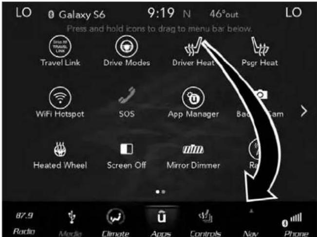
text_image
LO Galaxy S6 9:19 N 46°out Press and hold icons to drag to menu bar below. LO Travel Link Drive Modes Driver Heat Psgr Heat WiFi Hotspot SOS App Manager Bad Cam Heated Wheel Screen Off Mirror Dimmer Rad 87.9 Radio Media Climate Apps Controls Nav PhoneUconnect4C/4CNAVMainMenu
- Press the "Apps Ⓞ" button to open the App screen.
- Press and hold, then drag the selected App to replace an existing shortcut in the main menu bar.
The new shortcut will now be an active App/shortcut on the main menu bar.
CYBERSECURITY
Your vehicle may be a connected vehicle and may be equipped with both wired and wireless networks. These networks allow your vehicle to send and receive information. This information allows systems and features in your vehicle to function properly.
Your vehicle may be equipped with certain security features to reduce the risk of unauthorized and unlawful access to vehicle systems and wireless communications. Vehicle software technology continues to evolve over time and FCA US LLC, working with its suppliers, evaluates and takes appropriate steps as needed. Similar to a computer or other devices, your vehicle may require software updates to improve the usability and performance of your systems or to reduce the potential risk of unauthorized and unlawful access to your vehicle systems.
The risk of unauthorized and unlawful access to your vehicle systems may still exist, even if the most recent version of vehicle software (such as Uconnect software) is installed.
WARNING!
- Itisnotpossibletoknowortopredictallofthe possibleoutcomesifyourvehicle'ssystemsare breached.Itmaybepossiblethatvehiclesystems, includingsafetyrelatedsystems,couldbeimpaired oralossofvehiclecontrolcouldoccurthatmay resultinanaccidentinvolvingseriousinjuryor death.
- ONLYinsertmedia(e.g.,USB,SDcard,orCD)into yourvehicleifitcamefromattrustedsource.Media ofunknownorigincouldpossiblycontainmalicious software,andifinstalledinyourvehicle,itmay increasethepossibilityforvehiclesystemstobe breached.
- Asalways, if you experience unusual vehicle behavior, take your vehicle to your nearest authorized dealer immediately.
NOTE:
• FCA US LLC or your dealer may contact you directly regarding software updates.
- To help further improve vehicle security and minimize the potential risk of a security breach, vehicle owners should:
- Routinely check www.driveuconnect.com/support/software-update.html (U.S. Residents) or www.driveuconnect.ca (Canadian Residents) to learn about available Uconnect software updates.
- Only connect and use trusted media devices (e.g. personal mobile phones, USBs, CDs).
Privacy of any wireless and wired communications cannot be assured. Third parties may unlawfully intercept information and private communications without your consent. For further information, refer to "Data Collection & Privacy" in your Uconnect Owner's Manual Supplement or "Onboard Diagnostic System (OBD II) Cybersecurity" in "Getting To Know Your Instrument Panel".
446 MULTIMEDIA
UCONNECT SETTINGS
The Uconnect system uses a combination of buttons on the touchscreen and buttons on the faceplate located on the center of the instrument panel that allows you to access and change the customer programmable features. Many features can vary by vehicle.
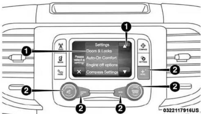
text_image
Settings Doors & Locks Please select a settings Auto-On Comfort Engine off options Compass Settings 0322117916US.Uconnect3ButtonsOnTheTouchscreenAndButtonsOn TheFaceplate
1 — Uconnect Buttons On The Touchscreen
2 — Uconnect Buttons On The Faceplate

text_image
LO + FM 87.9 9:53 % 60 Max LO Doors & Locks Auto On Comfort Engine Off Options Audio Phone Settings SinosXM Setup 0 Siding In AI AVI Audio Music Electric Appn Controls Appn Phone 1 2 3 4 5 6 7 8 9 0313117870USUconnect4C/4CNAVButtonsOnTheTouchscreenAnd ButtonsOnTheFaceplate
1 — Uconnect Buttons On The Touchscreen
2 — Uconnect Buttons On The Faceplate
Customer Programmable Features — Uconnect 3 Personal Settings
Push the MORE or SETTINGS button on the faceplate, then press the "Settings" button on the touchscreen (if equipped) to display the settings menu screen. In this mode the Uconnect system allows you to access programmable features that may be equipped such as Display, Units, Voice, Clock, Safety & Driving Assistance, Lights, Doors & Locks, Auto-On Comfort (if equipped), Engine Off Options, Trailer Brake, Audio, Compass Settings, Phone/Bluetooth, SiriusXM Setup (if equipped), Restore Settings, Clear Personal Data and System Information.
NOTE: Only one category may be selected at a time.
When making a selection, press the button on the touchscreen to enter the desired mode. Once in the desired mode, press and release the preferred setting until the button is highlighted. Once the setting is complete, either press the back arrow or the "Done" button on the touchscreen or the Back button on the faceplate to return to the previous menu. Pressing the Up or Down Arrow buttons on the touchscreen on the right side of the screen will allow you to toggle up or down through the list of available settings.
NOTE: All settings should be changed with the ignition in the RUN position.

448 MULTIMEDIA
Display
After pressing the "Display" button on the touchscreen, the following settings will be available.
| SettingNameSelectableOptions | ||
| DisplayModeAuto Manual | ||
| SetLanguageEnglish, Français, Español | ||
| TouchscreenBeepOn Off | ||
| FuelSaverDisplayOn Off | ||
| NOTE:The “Fuel Saver Display” feature will allow you to enable fuel saver mode and will be displayed in the instrument cluster display. | ||
Units—IfEquipped
After pressing "Units" on the touchscreen, the following will be available:
| SettingNameSelectableOptions | ||
| UnitsUS Metric | ||
Voice
After pressing the "Voice" button on the touchscreen, the following settings will be available:
| SettingNameSelectableOptions | ||
| VoiceResponseLengthBrief | Detailed | |
| ShowCommandListAlways | With Help Never | |
Clock&Date
After pressing the "Clock & Date" button on the touchscreen, the following settings will be available:
| SettingNameSelectableOptions | ||
| SetTime12 hour 24 hour | ||
| NOTE:Within the “Set Time” feature, press the corresponding arrow above and below the current time to adjust, then select “AM” or “PM.” | ||
| SetDateUp Arrow | Down Arrow | |
Safety/Assistance
After pressing the "Safety/Assistance" button on the touchscreen, the following settings will be available:
| SettingNameSelectableOptions | |||
| ParkSense—IfEquippedSound Only Sound & Display | |||
| NOTE:The ParkSense system scans for objects behind the vehicle when the transmission gear selector is in REVERSE and the vehicle speed is less than 7 mph (11 km/h). It provides an alert (audible and/or visual) to indicate the proximity to other objects. | |||
| FrontParkSenseChimeVolumeLow Med High | |||
| RearParkSenseChimeVolume—IfEquippedLow Med High | |||
| TiltMirrorsInReverse—IfEquippedOn Off | |||
| NOTE:When the “Tilt Mirrors In Reverse” feature is selected, the exterior side-view mirrors tilt downward when the ignition is in the RUN position and the transmission gear selector is in the REVERSE position. The mirrors move back to their previous position when the transmission is shifted out of REVERSE. | |||
| ParkViewBackupCameraActiveGuidelinesOn Off | |||
| NOTE:Your vehicle may be equipped with the ParkView Rear Back Up Camera Active Guidelines that allows you to see active guidelines over the ParkView Back up camera display whenever the gear selector is put into REVERSE. The image is displayed on the radio touchscreen display along with a caution note to “check entire surroundings” across the top of the screen. After five seconds, this note disappears. | |||
MULTIMEDIA 451
| SettingNameSelectableOptions | ||
| ParkViewBackupCameraDelayOn Off | ||
| NOTE:When the vehicle is shifted out of REVERSE (with camera delay turned OFF), the rear camera mode is exited and the navigation or audio screen appears again. When the vehicle is shifted out of REVERSE (with camera delay turned ON), the rear view image with dynamic grid lines is displayed for up to ten seconds after shifting out of REVERSE unless the forward vehicle speed exceeds 8 mph (12 km/h), the transmission is shifted into PARK or the ignition is switched to the OFF position. | ||
| RainSensingAutoWipers—IfEquippedOn Off | ||
| NOTE:When the “Rain Sensing Auto Wipers” feature is selected, the system automatically activates the windshield wipers if it senses moisture on the windshield. | ||
| HillStartAssist—IfEquippedOn Off | ||
| NOTE:When the “Hill Start Assist” feature is selected, the Hill Start Assist (HSA) system becomes active. | ||
Lights
After pressing the "Lights" button on the touchscreen, the following settings will be available:
| SettingNameSelectableOptions | ||
| HeadlightOffDelay0 sec 30 sec | ||
| 60 sec 90 sec | ||
| HeadlightIlluminationOnApproach | 0 sec 30 sec | |
| 60 sec 90 sec | ||
| NOTE:When the “Headlight Illumination On Approach” feature is selected, it allows the adjustment of the amount of time the headlights remain on when the doors are unlocked with the key fob. | ||
| HeadlightsWithWipers—IfEquipped | On Off | |
| AutoDimHighBeams—IfEquipped | On Off | |
| FlashLightsWithLockOn Off | ||
| NOTE:When the “Flash Lights With Lock” feature is selected, the exterior lights flash when the doors are locked or unlocked with the key fob. This feature may be selected with or without the sound horn on lock feature selected. | ||
Doors&Locks
After pressing the "Doors & Locks" button on the touchscreen, the following settings will be available:
| SettingNameSelectableOptions | |||
| AutoDoorLocks—IfEquipped | On Off | ||
| NOTE:When the “Auto Door Locks” feature is selected, all doors lock automatically when the vehicle reaches a speed of 15 mph (24 km/h). | |||
| AutoUnlockOnExitOn Off | |||
| NOTE:When the “Auto Unlock On Exit” feature is selected, all doors unlock when the vehicle is stopped, the transmission is in the PARK or NEUTRAL position and the driver’s door is opened. | |||
| SoundHornWithLockOff 1st Press 2nd Press | |||
| RemoteDoorUnlockAll Driver | |||
| NOTE:The “Remote Door Unlock” feature allows you to program your remote door locks to open “All doors” or only the “Driver door” with the first push of the key fob or grabbing the Passive Entry door handle. | |||
454 MULTIMEDIA
| SettingNameSelectableOptions | ||
| SoundHornWithRemote Start | On Off | |
| NOTE:When the “Sound Horn With Remote Start” feature is selected, the horn sounds when the remote start is activated. | ||
| MemoryLinkedToFob—IfEquipped | On Off | |
| NOTE:The “Memory Linked To Fob” feature provides automatic driver seat positioning to enhance driver mobility when entering and exiting the vehicle.The seat returns to the memorized seat location if “Memory Linked To Fob” is set to (On) when the key fob is used to unlock the door. | ||
| PassiveEntry—If Equipped | On Off | |
| NOTE:The “Passive Entry” feature allows you to lock and unlock the vehicle’s door(s) without having to push the key fob lock or unlock buttons. It automatically unlocks the doors when the outside door handle is grabbed. | ||
| FlashLightsWithLockOn Off | ||
| NOTE:When the “Flash Lights With Lock” feature is selected, the exterior lights flash when the doors are locked or unlocked with the key fob. This feature may be selected with or without the “Sound Horn With Lock” feature selected. | ||
AutoComfortSystems—IfEquipped
After pressing the "Auto-On Comfort" button on the touchscreen, the following settings will be available:
| SettingNameSelectableOptions | ||
| Auto-OnDriverHeated/Ventilated Seat&SteeringWheelWithVehicle Start—IfEquipped | On Off | |
| NOTE:When the “Auto-On Driver Heated/Ventilated Seat & Steering Wheel With Vehicle Start” feature is selected the driver’s heated seat and heated steering wheel will automatically turn on when temperatures are below 40° F (4.4°C).When temperatures are above 80° F (26.7°C) the driver vented seat will turn on. | ||
EngineOffOptions
After pressing the "Engine Off Options" button on the touchscreen, the following settings will be available:
| SettingNameSelectableOptions | ||
| EasyExitSeats—IfEquippedOn Off | ||
| HeadlightOffDelay0 sec 30 sec | ||
| 60 sec 90 sec | ||
| EngineOffPowerDelay0 sec 45 sec | ||
| 5 min 10 min | ||

456 MULTIMEDIA
Suspension—IfEquipped
After pressing the "Suspension" button on the touchscreen, the following settings will be available:
| SettingNameSelectableOptions | ||
| SoundHornWithLowerOn Off | ||
| FlashLightsWithLowerOn Off | ||
| AutoEntry/ExitSuspensionOn Off | ||
| NOTE:When the “Auto Entry/Exit Suspension” feature is selected, the vehicle automatically lowers from ride height position when vehicle shifted to park for easy entry/exit. | ||
| DisplaySuspensionMessagesAll Warning Only | ||
| AutomaticAeroMode(1500Model Only) | On Off | |
| NOTE:When the “Automatic Aero Mode” feature is selected, the Ride Height will automatically be adjusted depending on the vehicle speed. | ||
| TireJackModeOn Off | ||
| NOTE:When this feature is selected the air suspension system is disabled to prevent auto leveling of the suspension, while the vehicle is on a jack changing a tire. | ||

| SettingNameSelectableOptions | ||
| TransportModeOn Off | ||
| NOTE:When the “Transport Mode” feature is selected, the air suspension system is disabled to assist with flat bed towing. | ||
| WheelAlignmentModeOn Off | ||
| NOTE:The “Wheel Alignment Mode” feature prevents auto leveling of the air suspension while performing a wheel alignment service. Before performing a wheel alignment, this mode must be enabled. Refer to your authorized dealer for further information. | ||
TrailerBrake
After pressing the "Trailer Brake" button on the touchscreen, the following settings will be available:
| SettingNameSelectableOptions | |||
| TrailerSelectTrailer 1 Trailer 2 Trailer 3 Trailer 4 | |||
| TrailerBrakeTypeLight Electric Heavy Electric | Light EOH Heavy EOH | ||
458 MULTIMEDIA
Audio
After pressing the "Audio" button on the touchscreen, the following settings will be available:
| SettingNameSelectableOptions | ||||
| Balance/FadeFront | Back Left Right | |||
| NOTE:The “Balance/Fade” feature allows you to adjust the Balance and Fade settings. Press and drag the speaker icon or use the arrows to adjust, tap the “C” icon to readjust to the center. | ||||
| Equalizer+ | - | |||
| NOTE:When in the “Equalizer” display you may adjust the Bass, Mid and Treble settings. | ||||
| SpeedAdjustedVol-ume | Off 1 2 3 | |||
| NOTE:The “Speed Adjusted Volume” feature increases or decreases volume relative to vehicle speed. | ||||
| SurroundSound—IfEquipped | On Off | |||
| NOTE:The “Surround Sound” feature provides simulated surround sound mode. | ||||
MULTIMEDIA 459
| SettingNameSelectableOptions | ||
| AUXVolumeOffset—IfEquipped | On Off | |
| NOTE:The “AUX Volume Offset” feature provides the ability to tune the audio level for portable devices connected through the AUX input. | ||
| Loudness—IfEquipped | On Off | |
| NOTE:The “Loudness” feature improves sound quality at lower volumes. | ||
CompassSettings—IfEquipped
After pressing the "Compass Settings" button on the touchscreen, the following settings will be available:
| SettingNameSelectableOptions | |||||||||||||||
| Variance1 2 | 3 | 4 | 5 | 6 | 7 | 8 | 9 | 1 | 0 | 1 | 1 | 1 | 2 | 1 3 1 | |
| NOTE:Compass Variance is the difference between Magnetic North and Geographic North. To compensate for the differences the variance should be set for the zone where the vehicle is driven, per the zone map. Once properly set, the compass will automatically compensate for the differences, and provide the most accurate compass heading.Keep magnetic materials away from the top of the instrument panel, such as iPod's, Mobile Phones, Laptops and Radar Detectors. This is where the compass module is located, and it can cause interference with the compass sensor, and it may give false readings. | |||||||||||||||
| PerformCompassCalibration | On Off | ||||||||||||||
| NOTE:Press the “Calibration” button on the touchscreen to change this setting. This compass is self-calibrating, which eliminates the need to manually reset the compass. When the vehicle is new, the compass may appear erratic until it is calibrated. You may also calibrate the compass by pressing the “ON” button on the touchscreen and completing one or more 360-degree turns (in an area free from large metal or metallic objects). The compass will now function normally. | |||||||||||||||

text_image
1 2 3 4 5 6 7 8 9 10 11 12 13 14 15 ρCompassVarianceZoneMap
0440083509

Phone/Bluetooth
After pressing the "Phone/Bluetooth" button on the touchscreen, the following settings will be available:
| SettingNameSelectableOptions | |
| PairedPhonesList of Paired | Phones |
| NOTE:The “Paired Phones” feature shows which phones are paired to the Phone/Bluetooth system. For further information, refer to the Uconnect Owner’s Manual Supplement. | |
SiriusXMSetup—IfEquipped
After pressing the "SiriusXM Setup" button on the touchscreen, the following settings will be available:
| SettingNameSelectableOptions | ||
| TuneStartOn Off | ||
| ChannelSkipList of Channels | ||
| NOTE:SiriusXM can be programmed to exclude undesirable channels while scanning. To make your selection, press the “Channel Skip” button on the touchscreen, select the channels you would like to skip. | ||
| SettingNameSelectableOptions | |
| SubscriptionInfoSirius ID | |
| NOTE:New vehicle purchasers or lessees will receive a free limited time subscription to SiriusXM Satellite Radio with your radio. Following the expiration of the free services, it will be necessary to access the information on the Subscription Information screen to re-subscribe.1. Press the “Subscription Info” button on the touchscreen to access the Subscription Information screen.2. Write down the SIRIUS ID numbers for your receiver. To reactivate your service, either call the number listed on the screen or visit the provider online. | |
RestoreSettings
After pressing the "Restore Settings" button on the touchscreen, the following settings will be available:
| SettingNameSelectableOptions | ||
| RestoreSettingsYes Cancel | ||
| NOTE:When the “Restore Settings” feature is selected it will reset the Display, Clock, Audio, and Radio Settings to their default settings. If “Yes” is selected a pop-up will appear asking “Are you sure you want to reset your settings to default?” select “Yes” to restore, or “Cancel” to exit. | ||
ClearPersonalData
After pressing the "Clear Personal Data Settings" button on the touchscreen, the following settings will be available:
| SettingNameSelectableOptions | ||
| ClearPersonalDataYes Cancel | ||
| NOTE:When this feature is selected it will remove all personal data including Bluetooth devices and presets. If “Yes” is selected a pop-up will appear asking "Are you sure you want to clear all personal data?" select “Yes” to Clear, or “Cancel” to exit. | ||
SystemInformation
After pressing the "System Information" button on the touchscreen, the following settings will be available:
| SettingNameSelectableOptions | |
| SystemInformationSystem Software Information Screen | |
| NOTE:When the “System Information” feature is selected, a “System Software Information” screen will appear, displaying the system software version. You can also update your maps with a USB device. Please see an authorized dealer for further information. | |
Customer Programmable Features — Uconnect 4C/4C NAV Personal Settings
Press the "Apps" button on the touchscreen then press the "Settings" button on the touchscreen to display the settings menu screen. In this mode the Uconnect system allows you to access programmable features that may be equipped such as Display, Voice, Clock, Safety & Driving Assistance, Lights, Doors & Locks, Auto-On Comfort (if equipped), Engine Off Options, Trailer Brake, Audio, Phone/Bluetooth, SiriusXM Setup (if equipped), Restore Settings, Clear Personal Data and System Information.
NOTE: Only one category may be selected at a time.
When making a selection, press the button on the touchscreen to enter the desired mode. Once in the desired mode, press and release the preferred setting until a
check-mark appears next to the setting, showing that setting has been selected. Once the setting is complete, either press the back arrow button on the touchscreen or the Back button on the faceplate to return to the previous menu or press the "X" button on the touchscreen to close out of the settings screen. Pressing the Up or Down Arrow buttons on the touchscreen on the right side of the screen will allow you to toggle up or down through the list of available settings.
NOTE: All settings should be changed with the ignition in the RUN position.
Language
After pressing the "Language" button on the touchscreen, the following settings will be available:
| SettingName | SelectableOptions | ||
| Set Language | English | Français | Español |

466 MULTIMEDIA
Display
After pressing the "Display" button on the touchscreen, the following settings will be available:
| SettingNameSelectableOptions | ||
| DisplayModeAuto Manual | ||
| NOTE:When Day or Night is selected for the Display Mode, the usage of the Parade Mode feature will cause the radio to activate the Display Brightness Day control even though the headlights are on. | ||
| DisplayBrightnessWith HeadlightsON | + | - |
| NOTE:To make changes to the "Display Brightness with Headlights ON" setting, the headlights must be on and the interior dimmer switch must not be in the "party" or "parade" positions. | ||
| DisplayBrightnessWith HeadlightsOFF | + | - |
| NOTE:To make changes to the "Display Brightness with Headlights OFF" setting, the headlights must be off and the interior dimmer switch must not be in the "party" or "parade" positions. | ||
| SettingNameSelectable | Options | |
| SetThemePre-configured Themes | ||
| UnitsUS Metric | ||
| TouchscreenBeepOn Off | ||
| NavigationTurn-By-Turn InCluster—IfEquipped | On Off | |
| ControlsScreenTime-Out —IfEquipped | On Off | |
| FuelSaverDisplayin Cluster—IfEquipped | On Off | |
Voice
After pressing the "Voice" button on the touchscreen, the following settings will be available:
| SettingNameSelectable | eOptions | ||
| VoiceResponseLengthBrief | Detailed | ||
| ShowCommandListNever | w/Help Always | ||
468 MULTIMEDIA
Clock
After pressing the "Clock & Date" button on the touchscreen, the following settings will be available:
| SettingNameSelectableOptions | ||
| SyncTimeWithGPS—IfEquipped | On Off | |
| SetTimeHours- | + | |
| SetTimeMinutes- | + | |
| TimeFormat12hrs 24hrs | ||
| AM PM | ||
| ShowTimeInStatusBar—IfEquipped | On Off | |
| NOTE:The “Show Time In Status Bar” feature allows you to turn on or shut off the digital clock in the status bar. | ||
Camera
After pressing the "Camera" button on the touchscreen, the following settings will be available:
| SettingNameSelectableOptions | ||
| ParkViewBackupCameraDelayOn Off | ||
| NOTE:The “ParkView Backup Camera Delay” setting determines whether or not the screen will display the rear view image with dynamic grid lines for up to ten seconds after the vehicle is shifted out of REVERSE. This delay will be canceled if the vehicle’s speed exceeds 8 mph (13 km/h), the transmission is shifted into PARK, or the ignition is switched to the OFF position. | ||
| ActiveParkViewBackupCamera Guidelines | On Off | |
| NOTE:The “Active ParkView Backup Camera Guidelines” feature overlays the Rear Backup Camera image with active, or dynamic, grid lines to help illustrate the width of the vehicle and its project back up path, based on the steering wheel position when the option is checked. A dashed center line overlay indicates the center of the vehicle to assist with parking or aligning to a hitch/receiver. | ||
470 MULTIMEDIA
Safety&DrivingAssistance
After pressing the "Safety & Driving Assistance" button on the touchscreen, the following settings will be available:
| SettingNameSelectableOptions | |||
| ParkSenseSound Sound & Display | |||
| NOTE:The Rear Park Assist system will scan for objects behind the vehicle when the transmission gear selector is in RE-VERSE and the vehicle speed is less than 7 mph (11 km/h). | |||
| FrontParkSenseChime Volume | Low Med High | ||
| RearParkSenseChime Volume | Low Med High | ||
| TiltSideMirrorsInReverse—IfEquipped | On Off | ||
| NOTE:When the “Tilt Side Mirrors In Reverse” feature is selected, the outside side-view mirrors will tilt downward when the ignition is in the RUN position and the transmission gear selector is in the REVERSE position. The mirrors will move back to their previous position when the transmission is shifted out of REVERSE. | |||
MULTIMEDIA 471
| SettingNameSelectableOptions | ||
| RainSensingAutoWipers—IfEquipped | On Off | |
| NOTE:When the “Rain Sensing Auto Wipers” feature is selected, the system will automatically activate the windshield wipers if it senses moisture on the windshield. | ||
| HillStartAssist—IfEquipped | On Off | |
Mirrors&Wipers
After pressing the "Mirror and Wipers" button on the touchscreen, the following settings will be available:
| SettingNameSelectableOptions | ||
| HeadlightswithWipersOn Off | ||
472 MULTIMEDIA
Lights
After pressing the "Lights" button on the touchscreen, the following settings will be available:
| SettingNameSelectableOptions | ||
| HeadlightOffDelay+ | - | |
| NOTE:When the “Headlight Off Delay” feature is selected, the driver can choose to have the headlights remain on for 0, 30, 60, or 90 seconds when exiting the vehicle. | ||
| HeadlightIlluminationOn Approach | + | - |
| NOTE:When the “Headlight Illumination On Approach” feature is selected, the headlights will activate and remain on for 0, 30, 60, or 90 seconds when the doors are unlocked with the key fob. | ||
| HeadlightsWithWipers—If Equipped | On Off | |
| NOTE:When the “Headlights With Wipers” feature is selected, and the headlight switch is in the AUTO position, the headlights will turn on approximately ten seconds after the wipers are turned on. The headlights will also turn off when the wipers are turned off if they were turned on by this feature. | ||
MULTIMEDIA 473
| SettingNameSelectableOptions | ||
| AutoDimHighBeams—IfEquipped | On Off | |
| NOTE:When the “Auto Dim High Beams” feature is selected, the high beam headlights will deactivate automatically under certain conditions. | ||
| FlashLightsWithLockOn Off | ||
| NOTE:When the “Flash Lights With Lock” feature is selected, the exterior lamps will flash when the doors are locked or unlocked with the key fob. This feature may be selected with or without the sound horn on lock feature selected. | ||
| SteeringDirectedLightsOn Off | ||
| NOTE:When the “Steering Directed Lights” feature is selected, the headlights turn with the direction of the steering wheel. | ||
474 MULTIMEDIA
Doors&Locks
After pressing the "Doors & Locks" button on the touchscreen, the following settings will be available:
| SettingNameSelectableOptions | |||
| AutoDoorLocks—IfEquippedOn Off | |||
| NOTE:When the “Auto Door Locks” feature is selected, all doors lock automatically when the vehicle reaches a speed of 15 mph (24 km/h). | |||
| AutoUnlockOnExitOn Off | |||
| NOTE:When the “Auto Unlock On Exit” feature is selected, all doors unlock when the vehicle is stopped and the transmission is in the PARK or NEUTRAL position and the driver’s door is opened. | |||
| FlashLightsWithLockOn Off | |||
| NOTE:When the “Flash Lights With Lock” feature is selected, the front and rear turn signals flash when the doors are locked or unlocked with the key fob. This feature may be selected with or without the “Sound Horn With Lock” feature selected. | |||
| SoundHornWithLockOff 1st Press 2nd Press | |||
| SoundHornWithRemoteStartOn Off | |||
| 1stPressOfKeyFobUnlocksDriver Door All Doors | |||
| NOTE:When “1st Press Of Key Fob Unlocks: Driver Door” is selected, only the driver’s door unlocks on the first press of the key fob unlock button. You must push the key fob unlock button twice to unlock the passenger’s doors.When “All Doors” is selected, all of the doors unlock on the first push of the key fob unlock button.If the vehicle is programmed “1st Press Of Key Fob Unlocks: All Doors”, all doors will unlock no matter which Passive Entry equipped door handle is grasped. If “1st Press Of Key Fob Unlocks: Driver Door” is programmed, only the driver’s door will unlock when the driver’s door is grasped.With Passive Entry, if “1st Press Of Key Fob Unlocks: Driver Door” is programmed pushing the handle more than once only results in the driver’s door opening. If “Driver Door” is selected, once the driver’s door is opened, the interior door lock/unlock switch can be used to unlock all doors (or use key fob). | |||
| PassiveEntry—IfEquippedOn Off | |||
| NOTE:The “Passive Entry” feature allows you to lock and unlock the vehicle’s door(s) without having to push the key fob lock or unlock buttons. | |||
| PersonalSettingsLinkedToKeyFob—IfEquippedOn Off | |||
| NOTE:The “Personal Settings Linked To Key Fob” feature provides automatic driver seat positioning to enhance driver mobility when entering and exiting the vehicle.The seats return to the memorized seat location (if “Personal Settings Linked To Key Fob” is set to on) when the key fob is used to unlock the door. | |||

EngineOffOptions
After pressing the "Engine Off Options" button on the touchscreen, the following settings will be available:
| SettingNameSelectableOptions | ||
| EngineOffPowerDelay+ | - | |
| NOTE:When the “Engine Off Power Delay” feature is selected, the power window switches, radio, Uconnect phone system (if equipped), power sunroof (if equipped), and power outlets will remain active for up to ten minutes after the ignition is cycled to OFF. Opening either front door will cancel this feature. | ||
| HeadlightOffDelay+ | - | |
| NOTE:When the “Headlight Off Delay” feature is selected, the driver can choose to have the headlights remain on for 0, 30, 60, or 90 seconds when exiting the vehicle. | ||
AirSuspension—IfEquipped
After pressing the "Suspension" button on the touchscreen, the following settings will be available:
| SettingNameSelectableOptions | ||
| SoundHornWithLowerOn Off | ||
| NOTE:When the “Sound Horn With Lower” feature is selected, a short horn sound will occur when the key fob remote lower button is pushed. | ||
| FlashLightsWithLowerOn Off | ||
| NOTE:When the “Flash Lights With Lower” feature is selected, the front and rear turn signals will flash when the key fob remote lower button is pressed twice. This feature may be selected with or without the Sound Horn on Lower feature selected. | ||
| SuspensionDisplayMessagesAll Warning | ||
| AutomaticAeroMode(1500Model Only) | On Off | |
| NOTE:When the “Automatic Aero Mode” feature is selected, the Ride Height will automatically be adjusted depending on the vehicle speed. | ||
478 MULTIMEDIA
| SettingNameSelectableOptions | ||
| TireJackModeOn Off | ||
| NOTE:When the “Tire Jack Mode” feature is selected, the air suspension system is disabled to assist with changing a spare tire. | ||
| TransportModeOn Off | ||
| NOTE:When the “Transport Mode” feature is selected, the air suspension system lowers and then disables to assist with flat bed towing. | ||
| WheelAlignmentModeOn Off | ||
| NOTE:Before performing a wheel alignment, the “Wheel Alignment Mode” must be enabled. Refer to your authorized dealer for further information. | ||
Trailer
After pressing the "Trailer Brake" button on the touchscreen, the following settings will be available:
| SettingNameSelectableOptions | |||
| TrailerSelectTrailer 1 Trailer 2 Trailer 3 Trailer 4 | |||
| TrailerBrakeTypeLight Electric Heavy Electric | Light EOH Heavy EOH | ||
Audio
After pressing the "Audio" button on the touchscreen, the following settings will be available:
| SettingNameSelectableOptions | |||
| Balance/FadeFront Back | Left | Right | |
| NOTE:The “Balance/Fade” feature allows you to adjust the Balance and Fade settings. Press and drag the speaker icon or use the arrows to adjust, tap the “C” icon to readjust to the center. | |||
| Equalizer | + | - | |
| NOTE:When in the “Equalizer” display you may adjust the Bass, Mid and Treble settings. | |||
480 MULTIMEDIA
| SettingNameSelectableOptions | ||||
| SpeedAdjustedVolumeOff 1 | 2 3 | |||
| NOTE:The "Speed Adjusted Volume" feature increases or decreases volume relative to vehicle speed. | ||||
| SurroundSound—IfEquipped | On Off | |||
| NOTE:The "Surround Sound" feature provides simulated surround sound mode. | ||||
| AUXVolumeOffset—IfEquipped | On Off | |||
| NOTE:The "AUX Volume Offset" feature provides the ability to tune the audio level for portable devices connected through the AUX input. | ||||
| AutoPlayOn Off | ||||
Phone/BluetoothSettings
After pressing the "Phone/Bluetooth Settings" button on the touchscreen, the following settings will be available:
| SettingNameSelectableOptions | |
| DoNotDisturbList of Settings | |
| NOTE:Press “Do Not Disturb” to access the available settings. The following settings are: Auto Reply (both, text, call), Auto Reply Message (custom, default) and Custom Auto Reply Message (create message). | |
| PairedPhonesandAudioDevicesList Of Paired Phones and Audio Sources | |
| NOTE:The “Paired Phones and Audio Devices” feature shows which phones and audio sources are paired to the Phone and Audio Sources Settings system. For further information, refer to the Uconnect Owner’s Manual Supplement. | |
| SmartphoneProjectionManagerOn Off | |
482 MULTIMEDIA
SiriusXMSetup—IfEquipped
After pressing the "SiriusXM Setup" button on the touchscreen, the following settings will be available:
| SettingNameSelectableOptions | ||
| TuneStartOn Off | ||
| NOTE:The “Tune Start” feature begins playing the current song from the beginning when you tune to a music channel using one of the twelve presets, so you can enjoy the complete song. This feature occurs the first time the preset is selected during that current song. Tune Start works in the background, so you will not even realize it’s on, except that you will miss the experience of joining your favorite song with only a few seconds left to play. | ||
| ChannelSkipList of Channels | ||
| NOTE:SiriusXM can be programmed to designate a group of channels that are the most desirable to listen to or to exclude undesirable channels while scanning. This feature allows you to select the channels you would like to skip. | ||
| SubscriptionInfoSirius ID | ||
| NOTE:New vehicle purchasers or lessees will receive a free limited time subscription to SiriusXM Satellite Radio with your radio. Following the expiration of the free services, it will be necessary to access the information on the Subscription Information screen to re-subscribe.1. Press the “Subscription Info” button on the touchscreen to access the Subscription Information screen.2. Write down the Sirius ID numbers for your receiver. To reactivate your service, either call the number listed on the screen or visit the provider online.SiriusXM Travel Link is a separate subscription. | ||

ResetSettings
After pressing the "Reset Settings" button on the touchscreen, the following settings will be available:
| SettingNameSelectableOptions | ||
| ResetAppDrawerOK Cancel | ||
| RestoreSettingsOK Cancel | ||
| NOTE:When the “Restore Settings” feature is selected it will reset all settings to their default settings. | ||
| ClearPersonalDataYes Cancel | ||
| NOTE: When the “Clear Personal Data” feature is selected it will remove all personal data including Bluetooth devices and presets. | ||
SystemInformation
After pressing the "System Information" button on the touchscreen, the following settings will be available:
| SettingNameSelectableOptions | |
| SoftwareLicenseSystem Software Information Screen | |
| NOTE:When the “Software License” feature is selected, a “System Software Information” screen will appear, displaying the system software version. | |

484 MULTIMEDIA
STEERING WHEEL AUDIO CONTROLS — IF EQUIPPED
The remote sound system controls are located on the back surface of the steering wheel. Reach behind the wheel to access the switches.
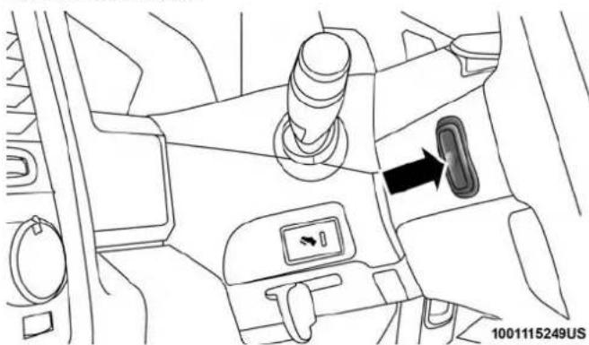
natural_image
Interior view of a car showing the dashboard and seatbelt with a directional arrow (no text or symbols)SteeringWheelAudioControls(RearviewOfSteering Wheel)
The right hand control is a rocker type switch with a push-button in the center. Pushing the top of the switch will increase the volume, and pushing the bottom of the switch will decrease the volume.
- Pushing the center button will make the radio switch between the various modes available (AM/FM/SXM or Media etc.).
The left hand control is a rocker type switch with a push-button in the center. The function of the left hand control is different depending on which mode you are in.
The following describes the left hand control operation in each mode.
Radio Operation
Pushing the top of the switch will SEEK up for the next listenable station and pushing the bottom of the switch will SEEK down for the next listenable station.
The button located in the center of the left-hand control will tune to the next preset station that you have programmed in the radio preset button.
Media Mode
Pushing the top of the switch once goes to the next track on the selected media (AUX/USB/Bluetooth). Pushing the bottom of the switch once goes to the beginning of the current track, or to the beginning of the previous track if it is within eight seconds after the current track begins to

CD Player — If Equipped
Pushing the top of the switch once will go to the next track on the CD. Pushing the bottom of the switch once will go to the beginning of the current track or to the beginning of the previous track if it is within eight seconds after the current track begins to play.
If you push the switch up or down twice, it plays the second track. If you push the switch up or down three times, it will play the third, etc.
IPOD/USB/MP3 CONTROL — IF EQUIPPED
Located inside the center console upper lid, this feature allows an iPod or external USB device to be plugged into the USB port.
iPod control supports the following: iPod/iPod classic, iPod mini, iPod nano, iPod shuffle, iPod touch, and iPhone devices. Some iPod software versions may not fully support the iPod control features. Please visit Apple's website for software updates.
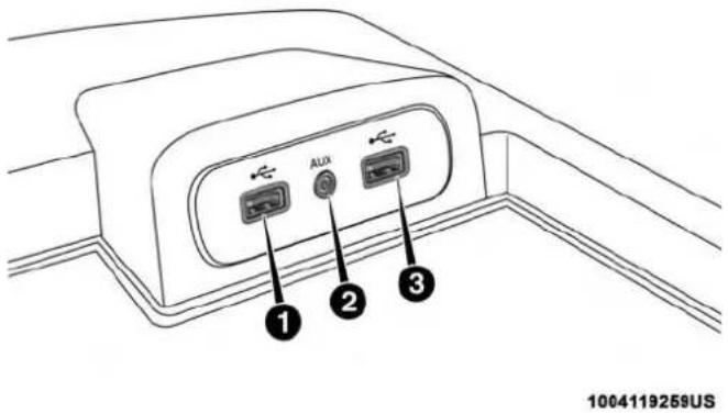
text_image
1 2 3 1004119259USCenterConsoleUSB/AUXMediaHub
1 — USB Port #1
2 — Aux Jack
3 — USB Port #2
For further information, refer to the Uconnect Owner's Manual Supplement or visit UconnectPhone.com.
Under certain conditions, the mobile phone being on in your vehicle can cause erratic or noisy performance from your radio. This condition may be lessened or eliminated by relocating the mobile phone antenna. This condition is not harmful to the radio. If your radio performance does not satisfactorily “clear” by the repositioning of the antenna, it is recommended that the radio volume be turned down or off during mobile phone operation when not using Uconnect (if equipped).
Regulatory And Safety Information
USA/CANADA
Exposure to Radio Frequency Radiation
The radiated output power of the internal wireless radio is far below the FCC and IC radio frequency exposure limits. Nevertheless, the wireless radio will be used in such a manner that the radio is 20 cm or further from the human body.
The internal wireless radio operates within guidelines found in radio frequency safety standards and recommendations, which reflect the consensus of the scientific community.
The radio manufacturer believes the internal wireless radio is safe for use by consumers. The level of energy emitted is far less than the electromagnetic energy emitted by wireless devices such as mobile phones. However, the use of wireless radios may be restricted in some situations or environments, such as aboard airplanes. If you are unsure of restrictions, you are encouraged to ask for authorization before turning on the wireless radio.
The following regulatory statement applies to all Radio Frequency (RF) devices equipped in this vehicle:
This device complies with Part 15 of the FCC Rules and with Industry Canada license-exempt RSS standard(s). Operation is subject to the following two conditions:
- This device may not cause harmful interference, and
- This device must accept any interference received, including interference that may cause undesired operation.
NOTE: Changes or modifications not expressly approved by the party responsible for compliance could void the user's authority to operate the equipment.
NOTE:
- This equipment has been tested and found to comply with the limits for a Class B digital device, pursuant to Part 15 of the FCC Rules. These limits are designed to provide reasonable protection against harmful interference in a residential installation. This equipment generates, uses and can radiate radio frequency energy and, if not installed and used in accordance with the instructions, may cause harmful interference to radio communications. However, there is no guarantee that interference will not occur in a particular installation.
- If this equipment does cause harmful interference to radio or television reception, which can be determined by turning the equipment off and on, the user is encouraged to try to correct the interference by one or more of the following measures:
- Increase the separation between the equipment and receiver.
- Consult an authorized dealer or an experienced radio technician for help.
488 MULTIMEDIA
UCONNECT VOICE RECOGNITION QUICK TIPS
Introducing Uconnect
Start using Uconnect Voice Recognition with these helpful quick tips. It provides the key Voice Commands and tips you need to know to control your Uconnect system.
If you see the NAV icon on the bottom bar, or in the Apps menus, of your touchscreen, you have the Uconnect 4C NAV system. If not, you have a Uconnect 4C system.

text_image
Please say a command Tune toUconnect3.0
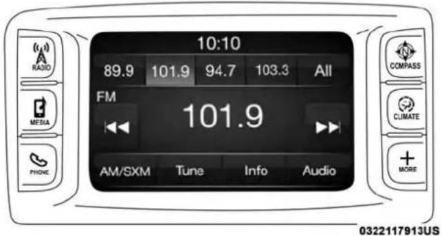
text_image
10:10 89.9 101.9 94.7 103.3 All FM 101.9 AM/SXM Tune Info Audio COMPASS CUMATE + MORE 0322117913USUconnect3


text_image
Listening... Say a command or say "Help" or "Cancel" Say things like: CallUconnect4C/4CNAV
Get Started
All you need to control your Uconnect system with your voice are the buttons on your steering wheel.
- Visit UconnectPhone.com to check mobile device and feature compatibility and to find phone pairing instructions.
- Reduce background noise. Wind noise and passenger conversations are examples of noise that may impact recognition.
- Speak clearly at a normal pace and volume while facing straight ahead. The microphone is located in the headliner and aimed at the driver.
- Each time you give a Voice Command, you must first push either the VR or Phone button, wait until afterthe beep, then say your Voice Command.
490 MULTIMEDIA
- You can interrupt the help message or system prompts by pushing the VR or Phone button and saying a Voice Command from current category.

text_image
① ② VR 1007126392USUconnectVoiceCommandButtons
1 — Push To Begin Radio Or Media Functions
2 — Push To Initiate, Answer, End A Phone Call, Or Send/Receive A Text
Basic Voice Commands
The basic Voice Commands below can be given at any point while using your Uconnect system.
Push the VR button 05VR. After the beep, say:
- "Cancel" to stop a current voice session
- "Help" to hear a list of suggested Voice Commands
- "Repeat" to listen to the system prompts again
Notice the visual cues that inform you of your voice recognition system's status. Cues appear on the top of the touchscreen.
Please say a command

Tune to

text_image
Listening Help Cancel 0415029429Uconnect3
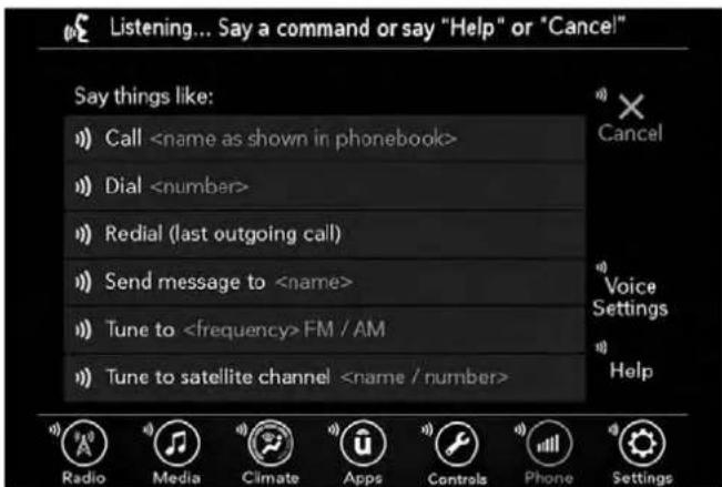
text_image
Listening... Say a command or say "Help" or "Cancel" Say things like: CallUconnect4C/4CNAV
492 MULTIMEDIA
Radio
Use your voice to quickly get to the AM, FM or SiriusXM Satellite Radio stations you would like to hear. (Subscription or included SiriusXM Satellite Radio trial required.)
Push the VR button _VR . After the beep, say:
• "Tunetoninety-five-point-five FM"
• " TunetoSatelliteChannelHits 1"
TIP: At any time, if you are not sure of what to say or want to learn a Voice Command, push the VR button and say "Help." The system provides you with a list of commands.
Please say a command

Tune to
Tune to Satellite
Change source to USB / AUX / ...
0415077826
Uconnect3.0
MULTIMEDIA 493
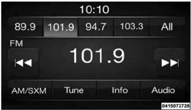
text_image
10:10 89.9 101.9 94.7 103.3 All FM 101.9 AM/SXM Tune Info Audio 0415072728Uconnect3
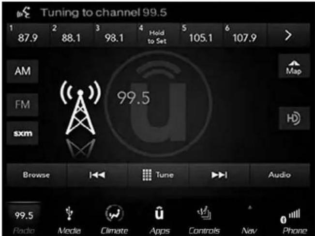
text_image
Tuning to channel 99.5 1 87.9 2 88.1 3 98.1 4 Hold to Set 5 105.1 6 107.9 > AM FM sxm 99.5 Browse |←→ | Tune |→→ | Audio 99.5 Radio Media Climate Apps Controls Nav PhoneUconnect4C/4CNAV
494 MULTIMEDIA
Media
Uconnect offers connections via USB, Bluetooth and auxiliary ports (If Equipped). Voice operation is only available for connected USB and AUX devices. (Remote CD player optional and not available on all vehicles.)
Push the VR button of VR. After the beep, say one of the following commands and follow the prompts to switch your media source or choose an artist.
• "ChangesourcetoBluetooth"
- "ChangesourcetoAUX"
- "ChangesourcetoUSB"
- "Play artist Beethoven"; "Play album Greatest Hits"; "PlaysongMoonlight Sonata"; "PlaygenreClassical"
TIP: Press the Browse button on the touchscreen to see all of the music on your USB device. Your Voice Command must match exactly how the artist, album, song and genre information is displayed.
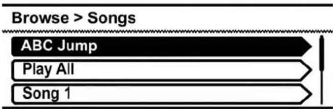
flowchart
graph TD
    A["ABC Jump"] --> B["Play All"]
    B --> C["Song 1"]
0416102327NA
Uconnect3.0
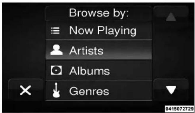
text_image
Browse by: Now Playing Artists Albums GenresUconnect3
MULTIMEDIA 495

text_image
Playing the song Good Vibes. Repeat Sound Round Shuttle USB USB AIJx Beatro Map Info Triks Beatro Good Vibes Beatropolis Browse Audio 87.9 Radio Media Climate Apps Controls Nav PhoneUconnect4C/4CNAV
496 MULTIMEDIA
Phone
Making and answering hands-free phone calls is easy with Uconnect. When the Phonebook button is illuminated on your touchscreen, your system is ready. Check UconnectPhone.com for mobile phone compatibility and pairing instructions.
Push the Phone button 📋. After the beep, say one of the following commands:
- "CallJohn Smith"
- "Dial123-456-7890 and follow the system prompts"
- "Redial(call previous outgoing phone number)"
- "Callback(call previous incoming phone number)"
TIP: When providing a Voice Command, push the Phone button 📋 and say "Call," then pronounce the name exactly as it appears in your phone book. When a contact has multiple phone numbers, you can say "Call John Smith work."
Please say a command

Listen
Ignore
Call
0701073934
Uconnect3.0
MULTIMEDIA 497

text_image
10:10 ROAM Nokia 9211 Redial Mute End Transfer Phone Ready Recent Calls Settings 0415072942Uconnect3
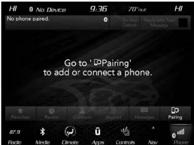
text_image
HI No Device 9:36 70° out HI No phone paired. 8 De Not Disturb Reply with Text Message Go to ' Pairing' to add or connect a phone. Favorites Recem Contacts Keypad Messages Pairing 87.9 Radio Media Climate Apps Controls Nav PhoneUconnect4C/4CNAVPhone
Voice Text Reply
Uconnect announces incomingtext messages. Push the Phone button 📊 and say “Listen.” (Must have compatible mobile phone paired to Uconnect system.)
- Once an incoming text message is read to you, push the Phone button 📋. After the beep, say: "Reply."
- Listen to the Uconnect prompts. After the beep, repeat one of the pre-defined messages and follow the system prompts.
| PRE-DEFINEDVOICETEXTREPLYRESPONSES | ||
| Yes. Stuck in traffic. See you later. | ||
| No. | Start without me. | I'll be late. |
| Okay. Where are you? | I will beminutes late. | |
| Call me. | Are you there yet? | |
| I'll call you later. | I need directions. | See you inof minutes. |
| I'm on my way. | Can't talk right | |
| I'm lost. Thanks. now. | ||
TIP: Your mobile phone must have the full implementation of the Message Access Profile (MAP) to take advantage of this feature. For details about MAP, visit UconnectPhone.com.
Apple iPhone iOS 6 or later supports reading incoming text messages only. To enable this feature on your Apple iPhone, follow these four simple steps:

text_image
Settings Airplane Mode Wi-Fi (GLOBAL ACCESS) Bluetooth Cellular Notifications Control Center Do Not Disturb General Display & Brightness 1 2 3 4 Uconnect Bluetooth No connected to "Mark Phone" HM1300 JBL Flip No Connected Uconnect No Connected Drive access Bluespan Uconnect Forget This Device Sync Contacts Sroups Phone Favorites Phone Recents All Contacts 1007135532USiPhoneNotificationSettings
1 — Select "Settings"
2 — Select "Bluetooth"
3 — Select The (i) For The Paired Vehicle
4 — Turn On "Show Notifications"
TIP: Voice Text Reply is not compatible with iPhone, but if your vehicle is equipped with Siri Eyes Free, you can use your voice to send a text message.
Climate (4C/4C NAV)
Too hot? Too cold? Adjust vehicle temperatures hands-free and keep everyone comfortable while you keep moving ahead. (If vehicle is equipped with climate control.)
Push the VR button 05VR. After the beep, say one of the following commands:
- "Setdrivertemperatureto70 degrees"
- "Setpassengertemperatureto70 degrees"
TIP: Voice Command for Climate may only be used to adjust the interior temperature of your vehicle. Voice Command will not work to adjust the heated seats or steering wheel if equipped.
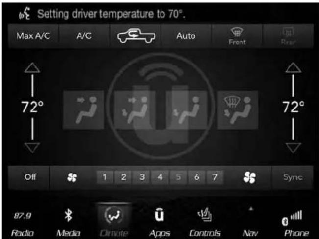
text_image
Setting driver temperature to 70°. Max A/C A/C Auto Front Rear 72° 72° Off 1 2 3 4 5 6 7 Sync 87.9 Radio Media Cimate Apps Controls Nov PhoneUconnect4C/4CNAVClimate
Navigation (4C NAV)
The Uconnect navigation feature helps you save time and become more productive when you do not know exactly how to get to where you want to go.
- To enter a destination, push the VR button (VR). After the beep, say: "Find address 800 Chrysler Drive Auburn Hills, Michigan."

500 MULTIMEDIA
2. Then follow the system prompts.
TIP: To start a POI search, push the VR button of VR. After the beep, say: "Findnearestcoffee shop."

text_image
LO Galaxy S6 9:19 N 46°out. LO Search in All Where To? View Map Home Work Information + Emergency Nav Settings 87.9 Radio Media Climate Apps Controls Nav PhoneUconnect4CNAVNavigation
SiriusXM Guardian (4C/4C NAV) — If Equipped
CAUTION!
SomeSiriusXMGuardianservices,includingSOSCall andRoadsideAssistanceCallwillNOTworkwithout anoperableLTE(voice/data)or3Gor4G(data)networkconnectioncompatiblewithyourdevice.
NOTE: Your vehicle may be transmitting data as authorized by the subscriber.
An included trial and/or subscription is required to take advantage of the SiriusXM Guardian services in the next section of this guide. To register with SiriusXM Guardian, press the Apps button on the 8.4-inch touchscreen to get started.
NOTE:SiriusXM Guardian is available only on equipped vehicles purchased within the continental United States, Alaska, Hawaii, and Canada. Services can only be used where coverage is available; see coverage map for details.

SOS Call

Theft Alarm Notification

Remote Door Lock/Unlock

Send & Go
Vehicle Finder
Stolen Vehicle Assistance
Remote Vehicle Start**
Remote Horn & Lights
Roadside Assistance Call
Vehicle Health Reports**
Vehicle Health Alert**
Performance Pages Plus**
**If vehicle is equipped.
Register (4C/4C NAV)
To unlock the full potential of SiriusXM Guardian in your vehicle, you must activate your SiriusXM Guardian services.
- Press the Apps icon on the bottom of your in-vehicle touchscreen.
-
Select the Activate Services icon from your list of apps.
-
Select "Customer Care" to speak with a SiriusXM Guardian Customer Care agent who will activate services in your vehicle, or select "Enter Email" to activate on the web.
For further information:
• U.S. residents visit: siriusxm.com/guardian
•Canadian residents visit: siriusxm.ca/guardian
Mobile App (4C/4C NAV)
You're only a few steps away from using remote commands and playing your favorite music in your car.

text_image
Uconnect USE YOUR NAME USE Password C:\Users\My DocumentsMobileApp

502 MULTIMEDIA
To use the Uconnect App:
- Download the Uconnect App to your mobile device.
- Press the Info button on the navigation bar at the bottom of the app for Vehicle Info.
- Press the Remote button on the navigation bar at the bottom of the app to Lock/Unlock, Remote Start, and activate your horn and lights remotely.
- Press the Location button on the navigation bar at the bottom of the app to bring up a map to locate your vehicle or send a location to your vehicle's navigation system.
- Press the Settings button in the upper left corner of the app to bring up app settings and access the Assist Call Centers.
NOTE: For further information please visit DriveUconnect.com(U.S. Residents) or DriveUconnect.ca (Canadian Residents).
SiriusXM Travel Link (4C NAV)
Need to find a gas station, view local movie listings, check a sports score or the 5-day weather forecast? SiriusXM Travel Link is a suite of services that brings a wealth of information right to your Uconnect 4C NAV syste m. Push the VR button 05VR. After the beep, say one of the following commands:
• " Showfuelprices"
• "Show5-dayweatherforecast"
• "Showextendedweather"
TIP: Traffic alerts are not accessible with Voice Command.
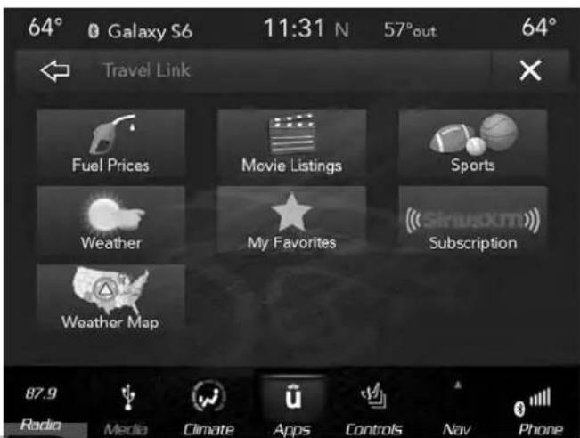
text_image
64° Galaxy S6 11:31 N 57°out 64° Travel Link Fuel Prices Movie Listings Sports Weather My Favorites Subscription Weather Map 87.9 Radio Media Climate Apps Controls Nav PhoneSiriusXMTravelLink

Siri Eyes Free — If Equipped
Siri lets you use your voice to send text messages, select media, place phone calls and much more. Siri uses your natural language to understand what you mean and responds back to confirm your requests. The system is designed to keep your eyes on the road and your hands on the wheel by letting Siri help you perform useful tasks.
To enable Siri, push and hold, then release the Uconnect Voice Recognition (VR) button on the steering wheel. After you hear a double beep you can ask Siri to play podcasts and music, get directions, read text messages and many other useful requests.

text_image
FM 87.7 12:07 Empty Empty Empty Empty Redial Galaxy S6 Siri Phone Ready End Do Not Disturb Contacts Rycem Dial Messaging Phone Settings Radio Media Climate Apps Nav Phone SettingsUconnect4C/4CNAVWith8.4-inchSiriEyesFree Available
Using Do Not Disturb
With Do Not Disturb, you can disable notifications from incoming calls and texts, allowing you to keep your eyes on the road and hands on the wheel. For your convenience, there is a counter display to keep track of your missed calls and text messages while you were using Do Not Disturb.

504 MULTIMEDIA
Do Not Disturb can automatically reply with a text message, a call or both, when declining an incoming call and send it to voicemail.
Automatic reply messages can be:
- "I am driving right now, I will get back to you shortly."
- Create a custom auto reply message up to 160 characters.
While in Do Not Disturb, Conference Call can be selected so you can still place a second call without being interrupted by incoming calls.
NOTE:
- Only the beginning of your custom message will be seen on the touchscreen.
- Reply with text message is not compatible with iPhones.
- Auto reply with text message is only available on phones that supporting Bluetooth MAP.
Android Auto — If Equipped
NOTE: Feature availability depends on your carrier and mobile phone manufacturer. Some Android Auto features may or may not be available in every region and/or language.
Android Auto allows you to use your voice to interact with Android's best-in-class speech technology through your vehicle's voice recognition system, and use your smartphone's data plan to project your Android powered smartphone and a number of its apps onto your Uconnect touchscreen. Connect your Android 5.0 (Lollipop), or higher, to one of the media USB ports, using the factory-provided USB cable, and press the new Android Auto icon that replaces your "Phone" icon on the main menu bar to begin Android Auto. Push and hold the VR button on the steering wheel, or press and hold the "Microphone" icon within Android Auto, to activate Android's VR, which recognizes natural voice commands, to use a list of your smartphone's features:
- Maps
•Music - Phone
- Text Messages
• Additional Apps
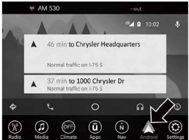
text_image
AM 530 46 min to Chrysler Headquarters Normal traffic on I-75 S 37 min to 1000 Chrysler Dr Normal traffic on I-75 SAndroidAutoOn8.4-inchDisplay
NOTE: Requires compatible smartphone running Android™ 5.0 Lollipop or higher and download app on Google Play. Android, Android Auto, and Google Play are trademarks of Google Inc.
Refer to your Uconnect Owner's Manual Supplement for further information.
Apple CarPlay — If Equipped
NOTE:Feature availability depends on your carrier and mobile phone manufacturer. Some Apple CarPlay features may or may not be available in every region and/or language.
Apple CarPlay allows you to use your voice to interact with Siri through your vehicle's voice recognition system, and use your smartphone's data plan to project your iPhone and a number of its apps onto your Uconnect touchscreen. Connect your iPhone 5, or higher, to one of the media USB ports, using the factory-provided Lightning cable, and press the new CarPlay icon that replaces your "Phone" icon on the main menu bar to begin Apple CarPlay. Press and hold the VR button on the steering wheel, or press and hold the "Home" button within Apple CarPlay, to activate Siri, which recognizes natural voice commands to use a list of your iPhone's features:
- Phone
• Music - Messages
- Maps
• Additional Apps

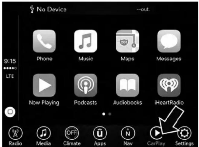
text_image
No Device --out. 9:15 LTE Phone Music Maps Messages Now Playing Podcasts Audiobooks iHeartRadio Radio Media Climate Apps Nav CarPlay SettingsAppleCarPlayOn8.4-inchDisplay
NOTE: Requires compatible iPhone. See dealer for phone compatibility. Data plan rates apply. Vehicle user interface is a product of Apple®. Apple CarPlay is a trademark of Apple Inc. iPhone is a trademark of Apple Inc., registered in the US and other countries. Apple terms of use and privacy statements apply.
Refer to your Uconnect Owner's Manual Supplement for further information.
General Information
The following regulatory statement applies to all Radio Frequency (RF) devices equipped in this vehicle:
This device complies with Part 15 of the FCC Rules and with Industry Canada license-exempt RSS standard(s). Operation is subject to the following two conditions:
- This device may not cause harmful interference, and
- This device must accept any interference received, including interference that may cause undesired operation.
NOTE: Changes or modifications not expressly approved by the party responsible for compliance could void the user's authority to operate the equipment.
Additional Information
© 2018 FCA US LLC. All rights reserved. Mopar and Uconnect are registered trademarks and Mopar Owner Connect is a trademark of FCA US LLC. Android is a trademark of Google Inc. SiriusXM and all related marks and logos are trademarks of SiriusXM Radio Inc.

Uconnect System Support:
• U.S. residents visit DriveUconnect.com or call: 1-877-855-8400(24 hours a day 7 days a week)
- Canadian residents visit DriveUconnect.ca or call: 1-800-465-2001(English) or 1-800-387-9983(French)
SiriusXM Guardian services support:
• U.S. residents call:1-844-796-4827
•Canadian residents call:1-877-324-9091
CD/DVD DISC MAINTENANCE
To keep a CD/DVD in good condition, take the following precautions:
- Handle the disc by its edge; avoid touching the surface.
- If the disc is stained, clean the surface with a soft cloth, wiping from center to edge.
- Do not apply paper or tape to the disc; avoid scratching the disc.
- Do not use solvents such as benzene, thinner, cleaners, or anti-static sprays.
-
Store the disc in its case after playing.
-
Do not expose the disc to direct sunlight.
- Do not store the disc where temperatures may become too high.
NOTE: If you experience difficulty in playing a particular disc, it may be damaged (e.g., scratched, reflective coating removed, a hair, moisture or dew on the disc), oversized, or have protection encoding. Try a known good disc before considering disc player service.


CUSTOMER ASSISTANCE
CONTENTS
■SUGGESTIONS FOR OBTAINING SERVICE FOR YOUR VEHICLE....510
□Prepare For The Appointment....510
□Prepare A List....510
□Be Reasonable With Requests .....510
■IF YOU NEED ASSISTANCE....510
□FCA US LLC Customer Center ..... 5 1 1
□FCA Canada Inc. Customer Center. . . . . . . . . . 5 1 1
□In Mexico Contact....511
□Puerto Rico And U.S. Virgin Islands . . . . . . . . . 5 1 1
□Customer Assistance For The Hearing Or Speech Impaired (TDD/TTY) .....512
□Service Contract....512
■WARRANTY INFORMATION .....513
■ MOPAR PARTS .....513
■REPORTING SAFETY DEFECTS .....513
□In The 50 United States And Washington, D.C. . .513
□In Canada....514
■PUBLICATION ORDER FORMS .....514
SUGGESTIONS FOR OBTAINING SERVICE FOR YOUR VEHICLE
Prepare For The Appointment
If you are having warranty work done, be sure to have the right papers with you. Take your warranty folder. All work to be performed may not be covered by the warranty. Discuss additional charges with the service manager. Keep a maintenance log of your vehicle's service history. This can often provide a clue to the current problem.
Prepare A List
Make a written list of your vehicle's problems or the specific work you want done. If you've had an accident or work done that is not on your maintenance log, let the service advisor know.
Be Reasonable With Requests
If you list a number of items and you must have your vehicle by the end of the day, discuss the situation with the service advisor and list the items in order of priority. At many authorized dealers, you may obtain a rental vehicle at a minimal daily charge. If you need a rental, it is advisable to make these arrangements when you call for an appointment.
IF YOU NEED ASSISTANCE
The manufacturer and its authorized dealer are vitally interested in your satisfaction. We want you to be happy with our products and services.
Warranty service must be done by an authorized dealer. We strongly recommend that you take the vehicle to an authorized dealer. They know your vehicle the best, and are most concerned that you get prompt and high quality service. The manufacturer's authorized dealer have the facilities, factory-trained technicians, special tools, and the latest information to ensure the vehicle is fixed correctly and in a timely manner.
This is why you should always talk to an authorized dealer service manager first. Most matters can be resolved with this process.
- If for some reason you are still not satisfied, talk to the general manager or owner of the authorized dealer. They want to know if you need assistance.
- If an authorized dealer is unable to resolve the concern, you may contact the manufacturer's customer center.
Any communication to the manufacturer's customer center should include the following information:
- Owner's name and address
- Owner's telephone number (home and office)
- Authorized dealer name
• Vehicle Identification Number (VIN)
• Vehicle delivery date and mileage
FCA US LLC Customer Center
P.O. Box 21-8004
Auburn Hills, MI 48321-8004
Phone: (866) 726-4636
FCA Canada Inc. Customer Center
P.O. Box 1621
Windsor, Ontario N9A 4H6
Phone: (800) 465-2001 English / (800) 387-9983 French
In Mexico Contact
In Mexico City: 5081-7568
Outside Mexico City: 1-800-505-1300
Puerto Rico And U.S. Virgin Islands
FCA Caribbean LLC
P.O. Box 191857
San Juan 00919-1857
Phone: (866) 726-4636
Fax: (787) 782-3345
512 CUSTOMER ASSISTANCE
Customer Assistance For The Hearing Or Speech Impaired (TDD/TTY)
To assist customers who have hearing difficulties, the manufacturer has installed special TDD (Telecommunication Devices for the Deaf) equipment at its customer center. Any hearing or speech impaired customer, who has access to a TDD or a conventional teletypewriter (TTY) in the United States, can communicate with the manufacturer by dialing 1-800-380-CHRY.
Canadian residents with hearing difficulties that require assistance can use the special needs relay service offered by Bell Canada. For TTY teletypewriter users, dial 711 and for Voice callers, dial 1-800-855-0511 to connect with a Bell Relay Service operator.
Service Contract
You may have purchased a service contract for a vehicle to help protect you from the high cost of unexpected repairs after the manufacturer's New Vehicle Limited Warranty expires. The manufacturer stands behind only the manufacturer's service contracts. If you purchased a manufacturer's service contract, you will receive Plan Provisions and an Owner Identification Card in the mail within three weeks of the vehicle delivery date. If you have questions about the service contract, call the manufacturer's Service Contract National Customer Hotline at 1-800-521-9922 (Canadian residents, call (800) 465-2001 English / (800) 387-9983 French).
The manufacturer will not stand behind any service contract that is not the manufacturer's service contract. It is not responsible for any service contract other than the manufacturer's service contract. If you purchased a service contract that is not a manufacturer's service contract, and you require service after the manufacturer's New Vehicle Limited Warranty expires, please refer to the contract documents, and contact the person listed in those documents.
We appreciate that you have made a major investment when you purchased the vehicle. An authorized dealer has also made a major investment in facilities, tools, and training to assure that you are absolutely delighted with the ownership experience. You will be pleased with their sincere efforts to resolve any warranty issues or related concerns.

WARNING!
Engineexhaust(internalcombustionenginesonly), someofitsconstituents,andcertainvehiclecomponentscontain,oremit,chemicalsknowntotheStateof Californiatocausecancerandbirthdefects,orother reproductiveharm.Inaddition,certainfluidscontainedinvehiclesandcertainproductsofcomponent wearcontain,oremit,chemicalsknowntotheStateof Californiatocausecancerandbirthdefects,orother reproductiveharm.
WARRANTY INFORMATION
See the Warranty Information Booklet for the terms and provisions of FCA US LLC warranties applicable to this vehicle and market.
MOPAR PARTS
Mopar fluids, lubricants, parts, and accessories are available from an authorized dealer. They are recommended for your vehicle in order to help keep the vehicle operating at its best.
REPORTING SAFETY DEFECTS
In The 50 United States And Washington, D.C.
If you believe that your vehicle has a defect that could cause a crash or cause injury or death, you should immediately inform the National Highway Traffic Safety Administration (NHTSA) in addition to notifying FCA US LLC.
If NHTSA receives similar complaints, it may open an investigation, and if it finds that a safety defect exists in a group of vehicles, it may order a recall and remedy campaign. However, NHTSA cannot become involved in individual problems between you, an authorized dealer or FCA US LLC.
To contact NHTSA, you may call the Vehicle Safety Hotline toll free at 1-888-327-4236 (TTY: 1-800-424-9153); or go to http://www.safercar.gov; or write to: Administrator, NHTSA, 1200 New Jersey Avenue, SE., West Building, Washington, D.C. 20590. You can also obtain other information about motor vehicle safety from http://www.safercar.gov.
514 CUSTOMER ASSISTANCE
In Canada
If you believe that your vehicle has a safety defect, you should contact the Customer Service Department immediately. Canadian customers who wish to report a safety defect to the Canadian government should contact Transport Canada, Motor Vehicle Defect Investigations and Recalls at 1-800-333-0510 or go to http://www.tc.gc.ca/roadsafety/.
PUBLICATION ORDER FORMS
To order the following manuals, you may use either the website or the phone numbers listed below. Visa, Mastercard, American Express, and Discover orders are accepted.
ServiceManuals
These comprehensive Service Manuals provide the information that students and professional technicians need in diagnosing/troubleshooting, problem solving, maintaining, servicing, and repairing FCA US LLC vehicles. A complete working knowledge of the vehicle, system, and/or components is written in straightforward language with illustrations, diagrams, and charts.
DiagnosticProcedureManuals
Diagnostic Procedure Manuals are filled with diagrams, charts and detailed illustrations. These practical manuals make it easy for students and technicians to find and fix problems on computer-controlled vehicle systems and features. They show exactly how to find and correct problems the first time, using step-by-step troubleshooting and drivability procedures, proven diagnostic tests and a complete list of all tools and equipment.
Owner's Manuals
These Owner's Manuals have been prepared with the assistance of service and engineering specialists to acquaint you with specific FCA US LLC vehicles. Included are starting, operating, emergency and maintenance procedures as well as specifications, capabilities and safety tips.
Call toll free at:
•1-800-890-4038(U.S.)
•1-800-387-1143(Canada)
Or
Visit us on the Worldwide Web at:
• www.techauthority.com (U.S.)

INDEX
516 INDEX
Adding Engine Coolant (Antifreeze)....387
Adding Fuel....293
Additives, Fuel . . . . . . . . . . . . . . . . . . . . . . . . . . . . . . . . . . . . . . . . . . . . . . . . . . . . . 294, 432
Adjust
Down....44, 46
Forward 44,46
Rearward....44,46
Up .44,46
Adjustable Pedals 57
Air Bag
Air Bag Operation....202
Air Bag Warning Light....199
Enhanced Accident Response .....208, 357
Event Data Recorder (EDR) .....357
If Deployment Occurs .....207
Knee Impact Bolsters . . . . . . . . . . . . . . . . . . . . . . . . . . . . . . . . . . . . . . . . . . . . . 203
Maintaining Your Air Bag System . . . . . . . . . . . . . . . . . 210
Maintenance.210
Transporting Pets . . . . . . . . . . . . . . . . . . . . . . . . . . . . . . . . . . . . . . . . . . . . . 236
Air Bag Light. . . . . . . . . . . . . . . . . . . . . . . . . . . . . . . . . . . . . . . . . . . . . . . . . . . . . . . . . . . 152, 199, 237
Air Cleaner, Engine (Engine Air Cleaner Filter). . . . . .370
Air Conditioner Maintenance....373
Air Conditioner Refrigerant . . . . . . . . . . . . . . . . . . . . . . . . . . . . . . . . . . . . . . . . . . . 373, 374
Air Conditioner System . . . . . . . . . . . . . . . . . . . . . . . . . . . . . . . . . . . . . . . . . . . . . . 373
Air Conditioning....93
Air Conditioning Filter . . . . . . . . . . . . . . . . . . . . . . . . . . . . . . . . . . . . . . . . . . . . . . . . . . . . . 96, 374
Air Conditioning, Operating Tips ..... 9 5
Air Filter . . . . . . . . . . . . . . . . . . . . . . . . . . . . . . . . . . . . . . . . . . . . . . . . . . . . . . . . . . . 370
Air Pressure Tires....407
Alarm Panic....2 2 Security Alarm....32, 153
Alterations/Modifications Vehicle 7
Android Auto....504
Antifreeze (Engine Coolant)....386 Capacities....436 Disposal....389
Anti-Lock Brake System (ABS)....166
Anti-Lock Warning Light....159
Apple CarPlay 505
Ashtray....126
Assist, Hill Start ..... 168
Audio Systems (Radio). . . . . . . . . . . . . . . . . . . . . . . . . . . . . . . . . . . . . . . . . . . . . . . . . 443
Auto Down Power Windows 97
Automatic Door Locks. 39
Automatic Headlights 71
Automatic High Beams 70
Automatic Temperature Control (ATC) .....94
INDEX 517
Automatic Transmission
Adding Fluid 393
Fluid And Filter Changes .....394
Fluid Level Check....391,392
Fluid Type . . . . . . . . . . . . . . . . . . . . . . . . . . . . . . . . . . . . . . . . . . . . . . . . . . . . . . . . . . . . 391, 439
Shifting. 252
Special Additives....392
A u x C o r d . . . . . . . . . . . . . . . . . . . . . . . . . . . . . . . . . . . . . . . . . . . . . . . . . . . . . 485
Auxiliary Switches. 127
Axle Fluid . . . . . . . . . . . . . . . . . . . . . . . . . . . . . . . . . . . . . . . . . . . . . . . . . . . . . . . . . . . 394, 395, 439
Axle Lubrication . . . . . . . . . . . . . . . . . . . . . . . . . . . . . . . . . . . . . . . . . . . . . . . . . . . . . . . . . 394, 395
Back-Up.290
Back-Up Camera....290
Battery. 154,367
Charging System Light . . . . . . . . . . . . . . . . . . . . . . . . . . . . . . . . . . . . . . . 154
Keyless Key Fob Replacement 23
Belts, Seat . . . . . . . . . . . . . . . . . . . . . . . . . . . . . . . . . . . . . . . . . . . . . . . . . . . . 237
Body Builders Guide. 7
Body Mechanism Lubrication .....380
B-Pillar Location . . . . . . . . . . . . . . . . . . . . . . . . . . . . . . . . . . . . . . . . . . . . . 402
Brake Assist System. 168
Brake Control System. . . . . . . . . . . . . . . . . . . . . . . . . . . . . . . . . . . . . . . . . . . . . . . . . . . 167
Brake Fluid 390,439
Brake System . . . . . . . . . . . . . . . . . . . . . . . . . . . . . . . . . . . . . . . . . . . . . . . . . 390, 428
Fluid Check....390
Master Cylinder 390
Parking.249
Warning Light....152
Brake/Transmission Interlock .....252
Bulb Replacement....327
Bulbs, Light....240, 327
.485
Cab Top Clearance Lights. . . . . . . . . . . . . . . . . . . . . . . . . . . . . . . . . . . . . . . 332
Camera 290
Camera, Rear....290
Capacities, Antifreeze (Engine Coolant) .....436
Capacities, Fluid . . . . . . . . . . . . . . . . . . . . . . . . . . . . . . . . . . . . . . . . . . . . . . . . 436
Caps, Filler Oil (Engine)....366, 370
Power Steering . . . . . . . . . . . . . . . . . . . . . . . . . . . . . . . . . . . . . . . . . . . . . . . . . . 273
Radiator (Coolant Pressure)....388
Carbon Monoxide Warning . . . . . . . . . . . . . . . . . . . . . . . . . . . . . . . . . . . . . . . . . . . . . . . . 237, 435
Cargo Light 74
Car Washes. 423
Cellular Phone 486
Center High Mounted Stop Light . . . . . . . . . . . . . . . . . . . . . . . . . . . . . . . 330
Center Seat Storage Compartment ..... 11 2
Change Oil Indicator....139
Changing A Flat Tire . . . . . . . . . . . . . . . . . . . . . . . . . . . . . . . . . . . . . . . . . . . . . . . . . 341
518 INDEX
Chart, Tire Sizing. 398
Check Engine Light (Malfunction Indicator Light)....163
Checking Your Vehicle For Safety .....236
Checks, Safety. 236
Child Restraint 211
Child Restraints Booster Seats....215
Child Seat Installation .....226, 228
How To Stow An unused ALR Seat Belt .....224
Infant And Child Restraints .....213
Locating The LATCH Anchorages .....220
Lower Anchors And Tethers For Children .....217
Older Children And Child Restraints .....214
Seating Positions . . . . . . . . . . . . . . . . . . . . . . . . . . . . . . . . . . . . . . . . . . . . . . . . . . . . . . . . . . . 216
Cigar Lighter....126
Clean Air Gasoline....432
Cleaning Wheels....416
Climate Control....80
Manual 80
Cold Weather Operation....248
Compact Disc (CD) Maintenance....507
Compact Spare Tire . . . . . . . . . . . . . . . . . . . . . . . . . . . . . . . . . . . . . . . . . . . . . . . . . . 414
Contract, Service....512
Cooling Pressure Cap (Radiator Cap) .....388
Cooling System. . . . . . . . . . . . . . . . . . . . . . . . . . . . . . . . . . . . . . . . . . . . . . . . . . . . . . . . . . . . . . 386
Adding Coolant (Antifreeze)....387
Coolant Capacity . . . . . . . . . . . . . . . . . . . . . . . . . . . . . . . . . . . . . . . . . . . . . 436
Coolant Level....386, 389
Disposal Of Used Coolant .389
Drain, Flush, And Refill .....386
Inspection . . . . . . . . . . . . . . . . . . . . . . . . . . . . . . . . . . . . . . . . . . . . . . . . . 389
Points To Remember....389
Pressure Cap. 388
Radiator Cap .388
Selection Of Coolant (Antifreeze) . . . . . . . . . . . . . . . . . . . . . . . . . . . . . . . . . . . . . . . . . . . . . . . . . . . . . . . . 386, 437
Corrosion Protection....422
Cruise Light....161
Cupholders. . . . . . . . . . . . . . . . . . . . . . . . . . . . . . . . . . . . . . . . . . . . . . . . . . . . . . . . . . 121
Customer Assistance....510
Customer Programmable Features . . . . . . . . . . . . . . . . . . . . . . . . . . . . . 465
Cybersecurity....444
Daytime Running Lights 69
Dealer Service....368
Defroster, Rear Window....80
Defroster, Windshield....238
Delay (Intermittent) Wipers 78
Diagnostic System, Onboard.....161
Differential, Limited-Slip .....270
INDEX 519
Dipsticks
Automatic Transmission....392
Power Steering....273
Disabled Vehicle Towing....354
Disposal
Antifreeze (Engine Coolant)....389
Disturb. 503
Door Ajar....155
Door Ajar Light. 155
Door Locks
Automatic....39
Doors. 34
Driver's Seat Back Tilt 41
Driving
Through Flowing, Rising, Or Shallow Standing Water....318
Dual Rear Wheels....345, 419, 429
Electrical Power Outlets .....122
Electric Brake Control System .....167
Anti-Lock Brake System....166
Electronic Roll Mitigation .....170, 175
Electronically Shifted Transfer Case . . . . . . . . . . . . . . . . . . 265
Electronic Range Select (ERS) .....258
Electronic Speed Control (Cruise Control) .....274
Electronic Stability Control (ESC) .....171
Electronic Throttle Control Warning Light .....154
Emergency Brake. .249
Emergency, In Case Of
Freeing Vehicle When Stuck . . . . . . . . . . . . . . . . . . . . . . . . . . . . . . . . . . . . . . . . . . . . 352
Hazard Warning Flasher .322
Jacking....341
Jump Starting . . . . . . . . . . . . . . . . . . . . . . . . . . . . . . . . . . . . . . . . . . . . . . . . 347
Emission Control System Maintenance. . . . . . . . . . . . . . 163
Engine .366
Air Cleaner . . . . . . . . . . . . . . . . . . . . . . . . . . . . . . . . . . . . . . . . . . . . . . . . 370
Break-In Recommendations .....248
Compartment Identification....366
Coolant (Antifreeze)....437
Exhaust Gas Caution .....237, 435
Fails To Start .....247
Flooded, Starting . . . . . . . . . . . . . . . . . . . . . . . . . . . . . . . . . . . . . . . . . . . . . . . . . . 247
Fuel Requirements. 432
Jump Starting . . . . . . . . . . . . . . . . . . . . . . . . . . . . . . . . . . . . . . . . . . . . . . 347
Oil 369,437
Oil Filler Cap . . . . . . . . . . . . . . . . . . . . . . . . . . . . . . . . . . . . . . . . . . . . . . . . . . . . . . . . . . . . . . . 366, 370
Oil Filter 370
Oil Selection . . . . . . . . . . . . . . . . . . . . . . . . . . . . . . . . . . . . . . . . . . . . . . 369
Oil Synthetic . . . . . . . . . . . . . . . . . . . . . . . . . . . . . . . . . . . . . . . . . . . . . . . . . . . . . 370
Overheating....350

Engine Oil Viscosity. .370
Enhanced Accident Response Feature .....208, 357
Entry System, Illuminated 7 7
Ethanol. 433
Exhaust Gas Cautions .....237, 435
Exhaust System . . . . . . . . . . . . . . . . . . . . . . . . . . . . . . . . . . . . . . . . . . . . . . . . . . . . . . . . . . . . 237, 384
Exterior Lighting. 68
Exterior Lights....68,240
Filters
Air Cleaner....370
Air Conditioning....96,374
Engine Fuel 437
Engine Oil. .370, 437
Engine Oil Disposal . . . . . . . . . . . . . . . . . . . . . . . . . . . . . . . . . . . . . . . . . . . . 370
Flashers
Turn Signals....73, 160, 240
Flash-To-Pass 71
Flat Tire Stowage. .346
Fluid, Brake....439
Fluid Capacities. . . . . . . . . . . . . . . . . . . . . . . . . . . . . . . . . . . . . . . . . . . . . . . . . . . . . . . . 436
Fluid Leaks. 240
Fluid Level Checks
Automatic Transmission....392
Brake 390
Power Steering . . . . . . . . . . . . . . . . . . . . . . . . . . . . . . . . . . . . . . . . . . . . . . . . . . . . 273
Fluids And Lubricants .....437
Fog Lights....73, 330
Fold Flat Load Floor 11 6
Fold-Flat Seats 41
Four-Way Hazard Flasher. . . . . . . . . . . . . . . . . . . . . . . . . . . . . . . . . . . . . . . . . . 322
Four Wheel Drive....261
Freeing A Stuck Vehicle . . . . . . . . . . . . . . . . . . . . . . . . . . . . . . . . . . . . . . . . . . 352
Front Axle (Differential) . . . . . . . . . . . . . . . . . . . . . . . . . . . . . . . . . . . . . . . . . . . . . 394
Fuel. 432
Adding 293
Additives....294, 432
Clean Air 432
Ethanol 433
Filler Cap (Gas Cap)....294
Filter 437
Gasoline....432
Light....158
Materials Added . . . . . . . . . . . . . . . . . . . . . . . . . . . . . . . . . . . . . . . . . . 294, 432
Methanol....433
Octane Rating....432
Requirements.432
Tank Capacity . . . . . . . . . . . . . . . . . . . . . . . . . . . . . . . . . . . . . . . . . . . . . . . . . . 436
Fuses 333

INDEX 521
Garage Door Opener (HomeLink) .....102
Gas Cap (Fuel Filler Cap)....294
Gasoline, Clean Air .....432
Gasoline, Reformulated .....432
Gear Ranges....253
Gear Select Lever Override....351
General Information. 184
Glass Cleaning . . . . . . . . . . . . . . . . . . . . . . . . . . . . . . . . . . . . . . . . . . . . . . . . . . . . . . . 426
Grocery Bag Retainer. 53
Gross Axle Weight Rating. . . . . . . . . . . . . . . . . . . . . . . . . . . . . . . . . . . . . . . . . . . . . . . . 297
Gross Vehicle Weight Rating....296
Guide
Body Builders....7
GVWR....294
Hazard
Driving Through Flowing, Rising, Or Shallow Standing
Water 318
Hazard Warning Flasher. . . . . . . . . . . . . . . . . . . . . . . . . . . . . . . . . . . . . . . . . . . . . . . 322
Headlights....328
Automatic....71
Cleaning....423
High Beam....70
High Beam/Low Beam Select Switch ..... 7 0
Passing 71
Switch....68
Head Restraints 53
Heated Mirrors 6 6
High Beam/Low Beam Select (Dimmer) Switch ..... 7 0
Hill Descent Control....176
Hill Descent Control Indicator .....176
Hill Start Assist....168
Hitches
Trailer Towing....300
Hoisting....395
HomeLink (Garage Door Opener)....102
Hood Prop....100
Hood Release....100
Hub Caps....346
Ignition 26
Switch 26
Illuminated Entry 77
Immobilizer (Sentry Key) 39
Inside Rearview Mirror . . . . . . . . . . . . . . . . . . . . . . . . . . . . . . . . . . . . . . . . . . . . . . . . . . . . . . . . . . . 59, 60, 322
Instrument Cluster
Descriptions 160
Instrument Panel Lens Cleaning .....425
Integrated Trailer Brake Controls. . . . . . . . . . . . . . . . . . . . 304
Interior Appearance Care....424

522 INDEX
Interior Lights. 74
Intermittent Wipers (Delay Wipers). 7 8
Introduction....4
Inverter Power....126
iPod/USB/MP3 Control. . . . . . . . . . . . . . . . . . . . . . . . . . . . . . . . . . . . . . . . . . . . . . 485
Jacking And Tire Changing. . . . . . . . . . . . . . . . . . . . . . . . . . . . . . . . . . . . . . . . . . . . . 341
Jack Location....341
Jack Operation....341
Jump Starting .347
Key Fob Panic Alarm 22
Programming Additional Key Fobs .....26, 31
Key Fob Battery Service (Remote Keyless Entry) ..... 2 3
Key Fob Programming (Remote Keyless Entry) ..... 2 6
Key-In Reminder. 28
Keyless Enter-N-Go....36,246
Lock The Vehicle's Doors . . . . . . . . . . . . . . . . . . . . . . . . . . . . . . . . . . . . . . . . . . . . . 453, 474
Passive Entry 36
Passive Entry Programming 36
Passive Entry Programming .....474
Keys 19
Replacement ....31
Sentry (Immobilizer) 30
Lane Change And Turn Signals....7 3
Lane Change Assist....7 4
Latches. 240
Hood....100
Lead Free Gasoline....432
Leaks, Fluid .....240
Life Of Tires 410
Light Bulbs....240
Lights. 240
Air Bag....152, 199, 237
Automatic Headlights 71
Brake Assist Warning....174
Brake Warning....152
Bulb Replacement....327
Cap Top Clearance .332
Cargo 74
Center Mounted Stop . . . . . . . . . . . . . . . . . . . . . . . . . . . . . . . . . . . . . . . . 330
Courtesy/Reading....75,76
Cruise 161
Daytime Running 69
Engine Temperature Warning....154
Exterior 240
Fog . . . . . . . . . . . . . . . . . . . . . . . . . . . . . . . . . . . . . . . . . . . . . . . . . . . . . . . . . . . . . . . . . 73, 330

INDEX 523
Four-Wheel Drive Indicator .....265
Hazard Warning Flasher....322
Headlights 68
High Beam 70
High Beam/Low Beam Select 70
Hill Descent Control Indicator .....176
Illuminated Entry 77
Interior....74,75,76
Low Fuel....158
Malfunction Indicator (Check Engine) .....155
Park....160
Passing....71
Seat Belt Reminder....152
Security Alarm....153
Service 327
Tire Pressure Monitoring (TPMS) .....157, 178
Traction Control....174
Transfer Case. 265
Turn Signal 328
Turn Signals....73,160,240
Warning Instrument Cluster Descriptions . . . .154, 160
Limited-Slip Differential .....270, 395
Loading Vehicle. 294
Tires....402
Load Shed
Battery Saver Mode .....150
Battery Saver On....150
Electrical Load Reduction....150
Intelligent Battery Sensor....150
Locks
Automatic Door 39
Child Protection 40
Power Door 35
Low Tire Pressure System. . . . . . . . . . . . . . . . . . . . . . . . . . . . . . . . . . . . . . . . . . . . . 178
Lubrication, Body . . . . . . . . . . . . . . . . . . . . . . . . . . . . . . . . . . . . . . . . . . . . . 380
Lug Nuts....345, 429
Maintenance Free Battery . . . . . . . . . . . . . . . . . . . . . . . . . . . . . . . . . . . . . . . . . . . . 367
Maintenance Schedule . . . . . . . . . . . . . . . . . . . . . . . . . . . . . . . . . . . . . . . . 361
Malfunction Indicator Light (Check Engine) . . . .155, 163
Manual, Service....514
Manual Transmission
Fluid Level Check....395
Media Hub 485
Memory Feature (Memory Seats) 4 1
Memory Seat....41, 46
Memory Seats And Radio 41
Methanol 433
Mirrors 59

524 INDEX
Electric Powered....6 2
Heated 6 6
Memory 46
Outside 61
Rearview....59,60,322
Trailer Towing 65
Modifications/Alterations
Vehicle 7
Monitor, Tire Pressure System. . . . . . . . . . . . . . . . . . . . . . . . . . . . . . . . . . . . . . . . 178
Mopar Parts....513
MP3 Control 485
Multi-Function Control Lever....6 9
Navigation System (Uconnect GPS) .....290
New Vehicle Break-In Period . . . . . . . . . . . . . . . . . . . . . . . . . . . . . . . . . . . . . . . 248
Occupant Restraints....185
Octane Rating, Gasoline (Fuel) .....432
Oil Change Indicator....139
Oil Change Indicator, Reset .....139
Oil, Engine. .369, 437
Capacity 436
Change Interval 369
Dipstick 367
Disposal 370
Filter . . . . . . . . . . . . . . . . . . . . . . . . . . . . . . . . . . . . . . . . . . . . . . . . . . . . . . . 370, 437
Filter Disposal . . . . . . . . . . . . . . . . . . . . . . . . . . . . . . . . . . . . . . . . . . . . . . . . . 370
Identification Logo....369
Materials Added To . . . . . . . . . . . . . . . . . . . . . . . . . . . . . . . . . . . . . . . . . . . . . . 370
Pressure Warning Light....154
Recommendation 369
Synthetic....370
Viscosity . . . . . . . . . . . . . . . . . . . . . . . . . . . . . . . . . . . . . . . . . . . . . . . . . . . . . . . . . . 370
Oil Filter, Change .370
Oil Filter, Selection. . . . . . . . . . . . . . . . . . . . . . . . . . . . . . . . . . . . . . . . . . . . . . . . . 370
Oil Pressure Light....154
Onboard Diagnostic System....161
Operating Precautions....161
Operator Manual Owner's Manual .... 5
Outside Rearview Mirrors 61
Overdrive....259
Overdrive OFF Switch .....259
Overheating, Engine . . . . . . . . . . . . . . . . . . . . . . . . . . . . . . . . . . . . . . . . . . . . . . 350
Owner's Manual (Operator Manual) .....514
Paint Care. 422
Panic Alarm....22
Parking Brake....249
ParkSense System, Rear. . . . . . . . . . . . . . . . . . . . . . . . . . . . . . . . . . . . . . . . . . . . . . . . . . . . . . . . . . . . . 277, 284
INDEX 525
Passive Entry 36
Pedals, Adjustable 57
Personal Settings....146
Pets....236
Placard, Tire And Loading Information .....402
Power
Distribution Center (Fuses)....334
Door Locks 35
Inverter....126
Mirrors 62
Outlet (Auxiliary Electrical Outlet) .....122
Seats 4 4
Sliding Rear Window....9 9
Steering.273
Take-Off Adapter....270
Take-Off Operation....270
Windows....97
Power Seats
Down 44,46
Forward....44, 46
Rearward....44,46
Recline 44
Ti 1 t . . . . . . . . . . . . . . . . . . . . . . . . . . . . . . . . . . . . . . . . . . . . . . . . . . . . . . . . . . . . . . . . . . . . 44, 46
Up 44,46
Power Steering Fluid....439
Pregnant Women And Seat Belts .....196
Preparation For Jacking .....341
Programmable Electronic Features. . . . . . . . . . . . . . . . . . . . 146
PTO (Power Take-Off) .....270
Radial Ply Tires . . . . . . . . . . . . . . . . . . . . . . . . . . . . . . . . . . . . . . . . . . . 408
Radiator Cap (Coolant Pressure Cap) .....386, 388
Radio Frequency General Information . . . . . . . . . . . . . . . . . . . . . . . . . . . . . . . . . . . . . . . . . . . . . . . . . . . . . . . 26, 30, 32, 39
Radio Operation....486
Rain Sensitive Wiper System 7 9
Rear Axle (Differential) .....394, 395
Rear ParkSense System . . . . . . . . . . . . . . . . . . . . . . . . . . . . . . . . . . . . . . . . . . . . . . . . . . . 277, 284
Reclining Rear Seats 43
Recreational Towing. . . . . . . . . . . . . . . . . . . . . . . . . . . . . . . . . . . . . . . . . . . . . . 313
Shifting Into Transfer Case Neutral (N) .....315
Shifting Out Of Transfer Case Neutral (N) .....317
Reformulated Gasoline. . . . . . . . . . . . . . . . . . . . . . . . . . . . . . . . . . . . . . . . . . . . . 432
Refrigerant....373,374
Release, Hood....100
Reminder, Seat Belt .....186
Remote Keyless Entry 21
Panic Alarm 22
Programming Additional Key Fobs .....26, 31

Remote Starting
Exit Remote Start Mode ..... 2 9
Uconnect Customer Programmable Features . . . . .455
Uconnect Settings 455
Replacement Keys 3 1
Replacement Tires 411
Reporting Safety Defects....513
Restraint, Head. 53
Restraints, Child 211
Rotation, Tires. 418
Safety Checks Inside Vehicle. . . . . . . . . . . . . . . . . . . . . . . . . . . . . . . . . . . . . . . . . . . . . 237
Safety Checks Outside Vehicle .....239
Safety Defects, Reporting .....513
Safety, Exhaust Gas . . . . . . . . . . . . . . . . . . . . . . . . . . . . . . . . . . . . . . . . . . . . . . . . . . 237
Safety Information, Tire . . . . . . . . . . . . . . . . . . . . . . . . . . . . . . . . . . . . . . . 396
Safety Tips....236
Schedule, Maintenance. . . . . . . . . . . . . . . . . . . . . . . . . . . . . . . . . . . . . . . . . 361
Seat Belt
Adjustable Upper Shoulder Belt Anchorage .....192
Automatic Locking Retractor (ALR) .....197
Lap/Shoulder Belt Operation....189
Seat Belt Reminder....152
Seat Belts....186,237
Adjustable Shoulder Belt .....192
Adjustable Upper Shoulder Anchorage .....192
Child Restraints 211
Extender....195
Front Seat 186,189
Inspection. 237
Lap/Shoulder Belt Untwisting .....191
Operating Instructions .....189
Pregnant Women....196
Reminder....186
Seat Belt Extender....195
Untwisting Procedure .....191
Seat Belts Maintenance. 425
Seats. 41, 43, 44, 46
Adjustment . . . . . . . . . . . . . . . . . . . . . . . . . . . . . . . . . . . . . . . . . . . . . . . . . . . . . . . . . . . . 41, 44, 46
Easy Entry 49
Folding Floor 1 1 6
Memory 46
Power....4 4
Rear Folding 41
Reclining Rear 43
Tilting 41
Security Alarm....32,153
Selection Of Coolant (Antifreeze) .....437
Sentry Key
Key Programming....31
INDEX 527
Sentry Key (Immobilizer) 30
Sentry Key Replacement....3 1
Service Assistance....510
Service Contract....512
Service Manuals....514
Settings, Personal .....146
Shifting....251
Automatic Transmission....252
Transfer Case....264
Transfer Case, Shifting Into Transfer Case Neutral (N) 315
Transfer Case, Shifting Out Of Transfer Case Neutral (N)....317
Shift Lever Override....351
Signals, Turn....73, 160, 240
Siri. 503
Sliding Rear Window, Power 9 9
Snow Chains (Tire Chains) .....417
Snow Plow....310
Snow Tires....413
Spare Tires. . . . . . . . . . . . . . . . . . . . . . . . . . . . . . . . . . . . . . . . . . . . . . . . . . . . . . . . . . . 413, 414, 415
Spark Plugs....437
Speed Control Accel/Decel....276
Cancel 277
Resume 277
Speed Control (Cruise Control) . . . . . . . . . . . . . . . . . . . . . . . . . . . . . . . . . . . . . 274
Starting. 244
Automatic Transmission....244
Button 26
Cold Weather 248
Engine Fails To Start . . . . . . . . . . . . . . . . . . . . . . . . . . . . . . . . . . . . . . . . . . . . . . . . 247
Starting Procedures (Gas Engines) .....244
Steering Power .....273 Tilt Column .....5 6 Wheel, Heated .....56, 57 Wheel, Tilt .....5 6
Steering Wheel Audio Controls .....484
Steering Wheel Mounted Sound System Controls . . . .484
Storage Compartment, Center Seat 112
Storage, Vehicle 95,422
Storing Your Vehicle....422
Sway Control, Trailer....175
Synthetic Engine Oil....370
Telescoping Steering Column 56
Temperature Control, Automatic (ATC) 9 4
Tilt
Down 44, 46

528 INDEX
Up .44,46
Tilt Steering Column 56
Tip Start....244
Tire And Loading Information Placard. . . . . . . . . . . . . . . 402
Tire Markings....396
Tires....239,406,413,420
Aging (Life Of Tires)....410
Air Pressure....406
Chains 417
Changing....341
Compact Spare . . . . . . . . . . . . . . . . . . . . . . . . . . . . . . . . . . . . . . . . . . . . . 414
Dual....345, 419, 429
General Information . . . . . . . . . . . . . . . . . . . . . . . . . . . . . . . . . . . . . . . . . . . 406, 413
High Speed....408
Inflation Pressure....407
Jacking....341
Life Of Tires....410
Load Capacity....402,403
Pressure Monitoring System (TPMS) .....157
Pressure Monitor System (TPMS)....178
Quality Grading . . . . . . . . . . . . . . . . . . . . . . . . . . . . . . . . . . . . . . . . . . . . . . . . . . . 420
Radial 408
Replacement 411
Rotation....418
Safety .396, 406
Sizes 398
Snow Tires . . . . . . . . . . . . . . . . . . . . . . . . . . . . . . . . . . . . . . . . . . . . . . . . . . . 413
Spare Tires . . . . . . . . . . . . . . . . . . . . . . . . . . . . . . . . . . . . . . . . . . . . . . . . . . . 413, 415
Spinning....409
Trailer Towing....303
Tread Wear Indicators .....410
Wheel Nut Torque . . . . . . . . . . . . . . . . . . . . . . . . . . . . . . . . . . . . . . . . . . . . 345, 429
Tire Safety Information. . . . . . . . . . . . . . . . . . . . . . . . . . . . . . . . . . . . . . . . . . . . 396
Tongue Weight/Trailer Weight . . . . . . . . . . . . . . . . . . . . . . . . . . . . . . . . . . . . . . . . 301
To Open Hood ....100
Torque Converter Clutch .....260
Towing. 296, 354
Disabled Vehicle....354
Guide....301
Recreational 313
Weight . . . . . . . . . . . . . . . . . . . . . . . . . . . . . . . . . . . . . . . . . . . . . . . . . . . . . . . 301
Towing Behind A Motorhome....313
Traction....318
Traction Control....170
Trailer Sway Control (TSC)....175
Trailer Towing. 296
Cooling System Tips....310
Hitches....300
Minimum Requirements....302
Mirrors 65
INDEX 529
Tips 309
Trailer And Tongue Weight. . . . . . . . . . . . . . . . . . . . . . . . . . . . . . . . . . . . . . . . . . . . . . 301
Wiring....308
Trailer Towing Guide . . . . . . . . . . . . . . . . . . . . . . . . . . . . . . . . . . . . . . . . . . . . . . . . 301
Trailer Weight....301
Transfer Case....395
Electronically Shifted .....265
Fluid 439
Transmission
Automatic....252,391
Fluid 439
Maintenance....391
Shifting. .251
Transporting Pets . . . . . . . . . . . . . . . . . . . . . . . . . . . . . . . . . . . . . . . . . . . . . . . . . 236
Tread Wear Indicators . . . . . . . . . . . . . . . . . . . . . . . . . . . . . . . . . . . . . . . . 410
Turn Signals....73,160,328
Uconnect
Customer Programmable Features .....455
Uconnect Settings .....446, 453
Uconnect Settings . . . . . . . . . . . . . . . . . . . . . . . . . . . . . . . . . . . . . . . . . . . . . . . . . 455
Uconnect Settings . . . . . . . . . . . . . . . . . . . . . . . . . . . . . . . . . . . . . . . . . . 474
Uconnect Settings
Customer Programmable Features....36
Customer Programmable Features .....453, 474
Passive Entry Programming 36
Passive Entry Programming .....453
Passive Entry Programming .....453, 474
Uniform Tire Quality Grades .....420
Universal Garage Door Opener (HomeLink). . . . . . . .102
Universal Transmitter....102
Unleaded Gasoline 432
Untwisting Procedure, Seat Belt .....191
U S B . . . . . . . . . . . . . . . . . . . . . . . . . . . . . . . . . . . . . . . . . . . . . . . . . . . . 485
Vehicle Identification Number (VIN) .....428
Vehicle Loading....294, 403
Vehicle Modifications/Alterations. 7
Vehicle Storage. .95, 422
Viscosity, Engine Oil . . . . . . . . . . . . . . . . . . . . . . . . . . . . . . . . . . . . . . . . . . . 370
Voice Command . . . . . . . . . . . . . . . . . . . . . . . . . . . . . . . . . . . . . . . . . . . . . . . 488
Voice Recognition System (VR) .....488
Warning Lights (Instrument Cluster Descriptions)....157
Warnings And Cautions 7
Warranty Information....513
Washers, Windshield....78, 367
Washing Vehicle....423
Water
Driving Through . . . . . . . . . . . . . . . . . . . . . . . . . . . . . . . . . . . . . . . . . . . . . . . . . 318
530 INDEX
Wheel And Wheel Tire Care . . . . . . . . . . . . . . . . . . . . . . . . . . . . . . . . . . . . . . . 416
Wheel And Wheel Tire Trim....416
Wheel Cover....346
Wheel Nut Torque . . . . . . . . . . . . . . . . . . . . . . . . . . . . . . . . . . . . . . . . . . . . . . . . . . . . 345, 346
Wind Buffeting....100
Window Fogging 95
Windows 97
Power 97
Reset Auto-Up 98
Windshield Defroster .....238
Windshield Washers....77,78,367
Fluid . . . . . . . . . . . . . . . . . . . . . . . . . . . . . . . . . . . . . . . . . . . . . . . . . . . . . . . . . . . . . . . . . . . 77, 367
Windshield Wiper Blades . . . . . . . . . . . . . . . . . . . . . . . . . . . . . . . . . . . . . . . . . . . . . . 381
Windshield Wipers 77
Wipers Blade Replacement . . . . . . . . . . . . . . . . . . . . . . . . . . . . . . . . . . . . . . . . . . . . 381
Wipers, Intermittent 78
Wipers, Rain Sensitive 7 9
INSTALLATIONOFRADIOTRANSMITTING EQUIPMENT
Specialdesignconsiderationsareincorporatedinto this vehicle'selectronicsystemtoprovideimmunitytoradio frequencysignals.Mobiletwo-wayradiosandtelephone equipmentmustbeinstalledproperlybytrainedpersonnel.Thefollowingmustbeobservedduringinstallation.
The positive power connections should be made directly to the battery and fused as closet to the battery as possible. Then negative power connections should be made to body sheet metal adjacent to the negative battery connection. This connections should not be fused.
Antennasfortwo-wayradiosshouldbemountedonthe rooffortherearareaofthevehicle.Careshouldbeused inmountingantennaswithmagnetbases.Magnetsmay affecttheaccuracyoroperationofthecompasson vehiclessoequipped.
Theantennacableshouldbeasshortaspracticaland routedawayfromthevehiclewiringwhenpossible.Use onlyfullyshieldedcoaxialcable.
Carefully match the antenna and cable to other radioto ensure alow Standing Wave Ratio (SWR).
Mobileradioequipmentwithoutputpowergreaterthan normalmayrequirespecialprecautions.
Allinstallationsshouldbecheckedforpossibleinterferencebetweenthecommunicationsequipmentandthe vehicle'selectronicsystems.


18DD-126-AD
©2018 FCA US LLC. ALL RIGHTS RESERVED.
RAM IS A REGISTERED TRADEMARK OF FCA US LLC.


FOURTH EDITION PRINTED IN THE U.S.A.