CMP-10BT - Label printer CITIZEN - Free user manual and instructions
Find the device manual for free CMP-10BT CITIZEN in PDF.

User questions about CMP-10BT CITIZEN
0 question about this device. Answer the ones you know or ask your own.
Ask a new question about this device
Download the instructions for your Label printer in PDF format for free! Find your manual CMP-10BT - CITIZEN and take your electronic device back in hand. On this page are published all the documents necessary for the use of your device. CMP-10BT by CITIZEN.
USER MANUAL CMP-10BT CITIZEN
MOBILE THERMAL PRINTER
MODEL CMP-10
CMP-10BT
User's Manual

natural_image
Line drawing of a printer with paper and control panel (no text or symbols)Declaration of Conformity
This printer conforms to the following Standards:
Low Voltage Directive (2006/95/EC) and EMC Directive (2004/108/EC)
LVD : E N 6 0 9 5 0
EMC : EN55022 Class B
EN61000-3-2
EN61000-3-3
EN55024
R&TTE: EN300328
This declaration is applied only for 230V model.
For Unites States
In order to comply with FCC radio-frequency radiation exposure guidance for an uncontrolled exposure, this device and its antenna must not be co-located or operating in conjunction with any other antenna or transmitter.
This device complies with Part 15 of the FCC Rules. Operation is subject to the following two conditions: (1) This device may not cause harmful interference, and (2) this device must accept any interference received, including interference that may cause undesired operation.
For Canada
Operation of this device is subject to the following two conditions: (1) this device may not cause interference, and (2) this device must accept any interference, including interference that may cause undesired operation of the device.
This installer of this radio equipment must ensure that the antenna is located or pointed such that it does not emit RF field in excess of Health Canada limits for the general population; consult Safety Code 6, obtainable from Health Canada's web site www.hc-sc.gc.ca/rpb
GENERAL PRECAUTIONS
●Before using this product, be sure to read through this manual. After having read this manual, keep it in a safe, readily accessible place for future reference.
●The information contained herein is subject to change without prior notice.
●Reproduction or transfer of part or all of this document in any means is prohibited without permission from CITIZEN SYSTEMS.
●Note that CITIZEN SYSTEMS is not responsible for any operation results regardless of missing, error, or misprinting in this manual.
●Note that CITIZEN SYSTEMS is not responsible for any trouble caused as a result of using options or consumables that are not specified in this manual.
●Except explained elsewhere in this manual, do not attempt to service, disassemble or repair this product.
●Note that CITIZEN SYSTEMS is not responsible for any damage attributable to incorrect operation/handling or improper operating environments which are not specified in this manual.
●Data are basically for temporary use, not stored for a long period or permanently. Please note that CITIZEN SYSTEMS is not responsible for damage or lost profit resulting from the loss of data caused by accidents, repairs, tests or other occurrence.
- If you find loss of information, error, or uncertain matter, please contact your CITIZEN SYSTEMS dealer.
- If you find any disordered or missing page (s), contact you CITIZEN SYSTEMS dealer for replacement.
CITIZEN is a registered trade mark of Citizen Holdings Co., Japan CITIZEN es una marca registrada de Citizen Holdings Co., Japón Company names and product names in this manual are trademarks or registered trademarks of relevant companies. Copyright © 2011 by CITIZEN SYSTEMS JAPAN CO., LTD.
SAFETY PRECAUTIONS
About Pictogram
Precautions and notices necessary to follow for preventing hazards to the user or other person or their properties are defined as shown below. Hazards and degrees of damage that may be caused by ignoring the instructions are categorized as shown below. Please be familiar with the content of these definitions before reading this manual.
 | Danger | Indicates the case that may result in death or serious injury. |
 | Warning | This symbol indicates that using the product improperly in defiance of this symbol may result in death or serious injury. |
 | Caution | This symbol indicates that using the product improperly in defiance of this symbol may result in injury or damage to properties. |
Definition of Pictogram

This symbol indicates the hazard that needs precautions.

This symbol indicates prohibited actions.

This symbol indicates mandatory actions.
Precautions in Handling Printer

WARNING

- If the product is kept in use under abnormal condition such as generation of heat, smoke, or abnormal odor, a fire may occur. Immediately turn the printer power off, and contact our service agent.

- If any foreign matter (metal tip, water, liquid) enters the product, immediately turn the printer power OFF, and contact our service agent. Ignoring this instruction may result in a fire.

CAUTION

- Do not place the printer on a shaky table or other unbalanced place. The printer may drop or fall resulting in injury.
-
Avoid using or storing in the following place. Damage to printer may be caused.
-
In a car parked in a sunny place, a place exposed to direct sunlight, near heat generating equipment, or the like.
- A place where temperature or humidity is excessively high or low, or its change is radical.
- A dusty place.
• A place likely to get a splash of water or liquid.
●Never drop nor give strong shock or vibration. Fault or damage may be caused.
●Avoid entry of foreign material. Otherwise, fault may occur.
- Do not use volatile liquid (thinner, benzine, etc.) or wet cloth when cleaning the printer. Deterioration or discoloration may occur. Use a dry, soft cloth for cleaning.
- Do not move the printer or give any shock or vibration to it while the printer is in operation or in standby operation. The printer power may be disconnected and the print data may be lost.
Precautions on Using Printer

WARNING

- Do not touch the print head or paper cutter while replacing print paper. Heated print head may cause burn. The cutter may cause injury to the hand.

CAUTION

●Use of print paper other than specified may result in not only deteriorated print quality but shortened life of print head (printing portion).

●Do not tap or rub the print head with edged or hard material.
- When dew condensation is present on the print head, dry it completely before printing. Printing with dew condensation may damage the print head.
●Battery replacement is carried out by our sales representative. Do not replace the battery by yourself. Otherwise, the warranty is void.
Precautions on Using Battery

DANGER

●Entering battery liquid may result in loss of eyesight. Immediately wash eyes with fresh water and get medical care.
- Keep the following in mind when handling battery. Otherwise, liquid leakage, heat generation, and explosion may result.
- Do not throw battery into fire or do not apply heat.
- Do not peel or scratch the external tube.
- Soldering is prohibited.
- Do not give strong shock to battery or throw it away.
- Do not short-circuit the positive and negative terminals with a metal such as metal wire.
●Never disassemble or modify battery. Otherwise, liquid leakage, heat generation, or explosion may occur.

WARNING

- If battery liquid attaches to skin or cloth, immediately wash it out with fresh water. Otherwise, skin disorder may be caused.

CAUTION

●Risk of explosion if battery is replaced by an incorrect type.
●Dispose of used batteries according to the instructions.

CAUTION

- Do not dip battery in water or sea water. Wet battery may generate heat or may be subject to corrosion.
●Do not use or leave battery at high temperature. Using or leaving battery in a place of high temperature may result in liquid leakage, deteriorated performance, or shortened lifetime. - Keep battery beyond the reach of a baby or child. Pay attention not to let a child take out the battery.
- If the battery is used for the first time, be sure to charge it completely before use.
- If any abnormality is found while the battery is in use, stop the operation and carry the battery in local sales agent.
●The battery in the printer is shipped partially charged. Please fully charge the battery prior to using the printer.
Precautions on Setting Print Paper

CAUTION

●Before printing, confirm that print paper is set straight forward at the exit from the print (thermal) head. Skewed setting may result in paper jamming.
● To prevent skewed insertion of paper, use the following form for the end of paper.


Precautions on Using Thermal Paper (Print Paper)

CAUTION

●Print density may change with the kind of print paper. Print density is adjusted by the Print Density Set command in Command Reference. For details, refer to Command Reference (Separate sheets).
- Observe the following when using thermal paper. Thermal paper is not resistant to discoloration, deterioration in quality, and thin printing.
- Do not let printed thermal paper exposed to light for a long time.
- A void exposure to high temperature, humidity, liquid, or sunlight.
- When keeping the printer thermal paper on a board, do not use paste, adhesive, or adhesive tape containing volatile organic solvent.
- For long-time storage, use thermal paper of high storage type or copy it with plain paper copier.
- A void contact with a film of vinyl chloride for a long time.
- A void using ammonia. Do not put thermal paper near the paper copied by use of ammonia.
- A void putting sweat or grease from your hands on the surface (printed or to be printed) of thermal paper.
- S tore thermal paper in a dark place with average temperature below 25°C and relative humidity below 65%.
●Using print paper with a thickness outside the recommended range may cause improper print quality.
Precautions on Using Special Serial Cable

WARNING

●With one side of the connector connected to this product, do not touch the metal part of the other connector.

CAUTION

●Static electricity may cause breakdown of internal circuit of this product.
- Do not leave this product with a cable wound around it for a long time. Disconnection or discoloration may result.
●Plugging and unplugging the contactor shall be done securely in the correct direction.
Precautions on Using AC Adapter

CAUTION

- Do not use the product at a voltage and frequency other than specified.
●Do not use AC adapter other than specified.
●Before use, confirm that the power receptacle has sufficient capacity. - Do not connect to the power receptacle where multiple connections are used.
- Do not step on, tap, or put any object, on the cable of the AC adapter.
●Before connecting or disconnecting AC adapter, turn the printer power OFF. Do the operation securely.
THE TABLE OF CONTENTS
1. INTRODUCTION ...... 11
1.1 Features 11
1.2 Included and Optional Accessories 12
1.3 Type Classification 12
2. GENERAL SPECIFICATIONS ......13
3. EXPLANATION OF PRINTER PARTS......16
3.1 LED Indicators 16
3.2 Communication Port and Switch 17
3.3 Inside of Paper Cover 18
3.4 Buzzer 18
3.5 Bottom Surface and Battery Cover 19
3.6 Dimensions and Views 20
4. OPERATION ......21
4.1 Replacing the Paper Roll 21
4.2 Method of Charging 22
4.3 Communication by IrDA 23
4.4 Communication Via Serial Port (Cable) 24
4.5 Communication by Bluetooth 25
4.6 Reading Mag Stripe Card (Only Model with Built-in Mag Stripe Card Reader) 25
4.7 DIP Switch Setting 26
4.8 Setup menu function (Firmware after Ver 2.20EN) .... 27
5. FUNCTION ......29
5.1 Auto Power OFF 29
5.2 Interface Selection 29
5.3 Low Battery Detection 29
5.4 Monitoring the Print Head Overheating 30
5.5 Self Testing and Internal Settings 30
5.6 Print Area 30
- LIST OF COMMANDS......31
- MAINTENANCE AND SERVICE ....33
- APPENDIX HANDLING BELT CLIP KIT ....34
8.1 How to Mount Belt Clip 34
8.2 Mounting Rubber Feet 34
1. INTRODUCTION
CMP-10 is a compact, full featured portable line thermal printer, which can be used in a large variety of job environments ranging from door-to-door sales through small and mid-sized catering establishments, car-rentals, parking lots, field services to on-board sales on land, sea and air.
IrDA/Bluetooth communication with a PDA or similar device is useful for business activities at the point of sale or service.
Easily worn on the belt it is a highly efficient device for printing plain text and graphic receipts on demand plus logos, bar codes and other graphic elements.
1.1 Features
●Small and lightweight.
●High speed and low noise emission of the line thermal printing mechanism.
●Long-life printing head with high reliability.
●Easy paper-handling, owing to the paper-drop-in style.
●The large-capacity Lithium-ion rechargeable battery allows an extensive amount of printing with a single charge.
●Built-in IrDA.
● Built-in Bluetooth® function. (CMP-10BT)
●Built-in mag stripe card reader. (Option)
●Choice of paper-roll diameters – Max. 40 or 50 mm.
1.2 Included and Optional Accessories
When unpacking the package, confirm the availability of:
●Printer unit: 1 piece
●Sample paper roll: 1 roll
●AC adapter: 1 piece
-User's manual: 1 copy
E (European) model
●Belt clip kit 1 set
(Belt clip, 2 × screws, 2 × rubber feet)
Please refer to the Appendix for how to mount belt clip and rubber feet.
Optional Accessory for European model: Serial Cable CA10-01
U (North America) model
●Serial Cable CA10-01
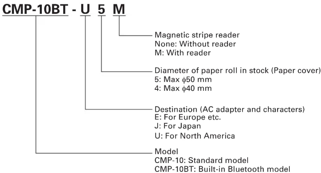
1.3 Type Classification
Classified by the following designation.
flowchart
graph TD
    A["CMP-10BT - U 5 M"] --> B["Magnetic stripe reader"]
    B --> C["None: Without reader"]
    B --> D["M: With reader"]
    A --> E["Diameter of paper roll in stock (Paper cover)"]
    E --> F["5: Max φ50 mm"]
    E --> G["4: Max φ40 mm"]
    A --> H["Destination (AC adapter and characters)"]
    H --> I["E: For Europe etc."]
    H --> J["J: For Japan"]
    H --> K["U: For North America"]
    A --> L["Model"]
    L --> M["CMP-10: Standard model"]
    L --> N["CMP-10BT: Built-in Bluetooth model"]
This user's manual is compiled for E/U destination model.
2. GENERAL SPECIFICATIONS
| Feature Parameters | |
| Printing system Direct thermal printing | |
| Printing speed 50 mm/sec | |
| Printing head Total dots: 384 | Dot density: 8 dots/mmPrinting width: 48 mm |
| Emulation ESC/POS commands plus extra commands for specific printer features | |
| Characters ASCII Code, Alphanumeric characters, International characters, Windows Code page | |
| Characters per line | FONT A: 32 characters/line, FONT B: 42 characters/line |
| Dot matrix | FONT A: 12H × 24V, FONT B: 9H × 16V |
| Bar code type UPC-A/E, JAN(EAN)13/8 columns, ITF,CODE39, CODE128, CODABAR, CODE93 | |
| Paper feed system Friction feed | |
| Paper width 58 ±0.5 mm | |
| Paper thickness 60 - 65 μm | |
| Recommended paper TF50-KS-E2D (Nippon Paper) | |
| Paper roll maximum diameter | 40 mm (CMP-10-×4), 50 mm (CMP-10-×5) |
| Minimum core diameter 8 mm | |
| Interfaces | IrDA version 1.0Bluetooth version 1.2Serial interface (by serial cable - option) |
| IrDA interface Mode: Infrared transceiver mode | |
| Bluetooth interface Transfer method: Bluetooth 1.2 compliant (CMP-10BT only) Frequency: 2.4 GHzModulation method: FH method (Frequency hopping spectrum diffusion method)Hypothetical interference distance: 10 mTransfer rate: 723.2k/57.6k bps (Transfer rate between Bluetooth module only)The communication speed between Bluetooth and the printer is 115.2kbps.Transfer capacity: Up to +4 dBm (Class 2 & Class 3)Coding: 128 bitSecurity level: LinkStandard PIN specification: Prepared (16 digits)PIN code: Lower 4 digits of the BD addressProfile: Serial Port Profile | |
| Serial interface Speed: 1200, 2400, 4800, 9600, 19200, 38400, 57600, 115200 bpsInterface: Bidirectional serial communicationSignal level: RS-232CData lenght: 8 bitsStart bit: 1 bitStop bit: 1 bitParity: NoneFlow control: Xon/XoffConnector: Motorola Star Tac | |
| Input buffer 64 KB | |
| Mag stripe reader Track 1, 2, 3 | |
| LED color Power LED: GREEN and REDCharge LED: GREEN and RED | |
| Operation switches Power switch | 1, LF switch 1 |
| Sensors and error monitoring Paper end sensor, Open cover sensor,Head temperature, Low battery | |
| Power consumption Idle - approximately 2WWhen printing - approximately 15W | |
| Battery Battery type: Li-ion battery packCell Voltage: 3.7 VNumber of cells: 2Battery pack voltage: 7.4 VBattery pack capacity: 2000 mAh | |
| Battery charging time Approximately 3 hours by main unit + AC adapter | |
| Maximum lines printed with 30,000 linesfully charged battery (At temperature 20°C, standard setting, alphanumeric slide pattern printing. The number of lines may be changed by such condition astemperature, etc.) | |
| Power supply monitoring Auto P | Power OFF (programmable - from 1 to 60 min.)Low battery monitoring included. |
| AC adapter Model: 10AD-JU (for | Japan, USA, and Canada)10AD-E (Europe)Input voltage 90 V - 264 V ACOutput voltage 9.0 V DC 1.0 A |
| Operating environment Temperature | 5 – 40°CHumidity: 35 – 80% RH (No dew condensation) |
| Storage environment Temperature | -20 – 60°CHumidity: 10 – 90% RH (No dew condensation) |
| Reliability Print head: 100,000,000 | pulses or 50km(Normal temperature, 12.5% density, rated energy)Mechanism: 15,000,000 lines |
| Safety standard and EMI UL, c-UL | TUV, GS, PSE (AC Adapter only)Vccl B, CE Marking, Fcc B |
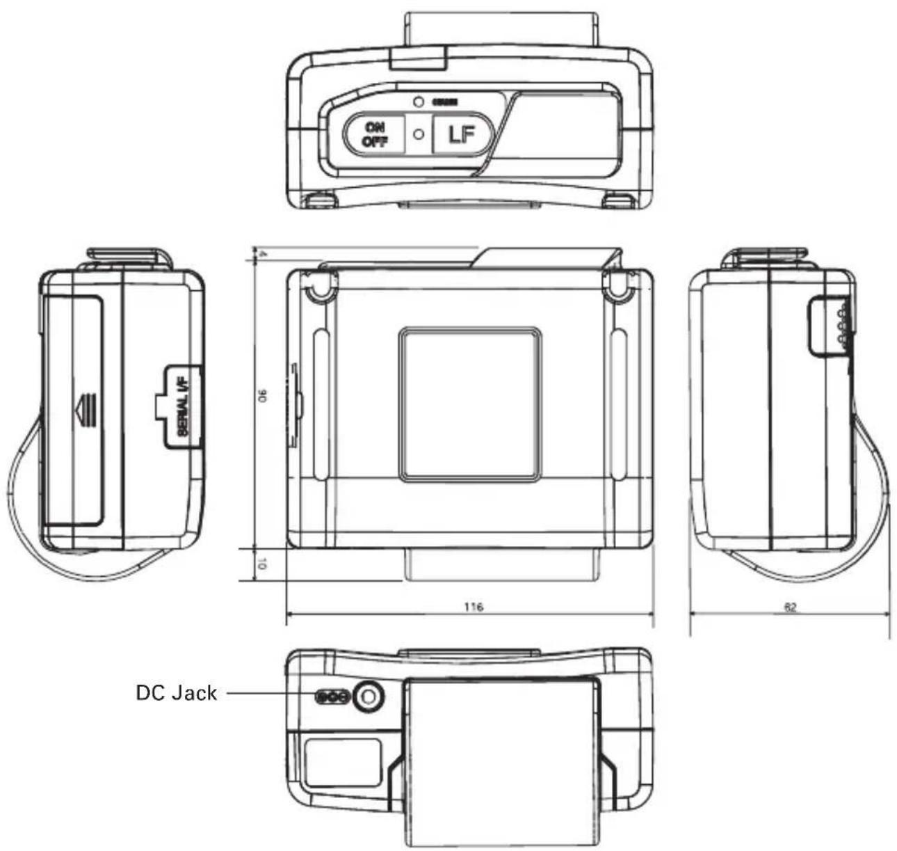
| Dimensions | 116 (W) × 104 (D) × 63 (H) mm(50 mm paper cover + Mag stripe reader) |
| Weight Approx. 370 g (with battery and belt clip without paper) | |
| Options | Serial Cable, Mag Stripe card reader (Factory option) |
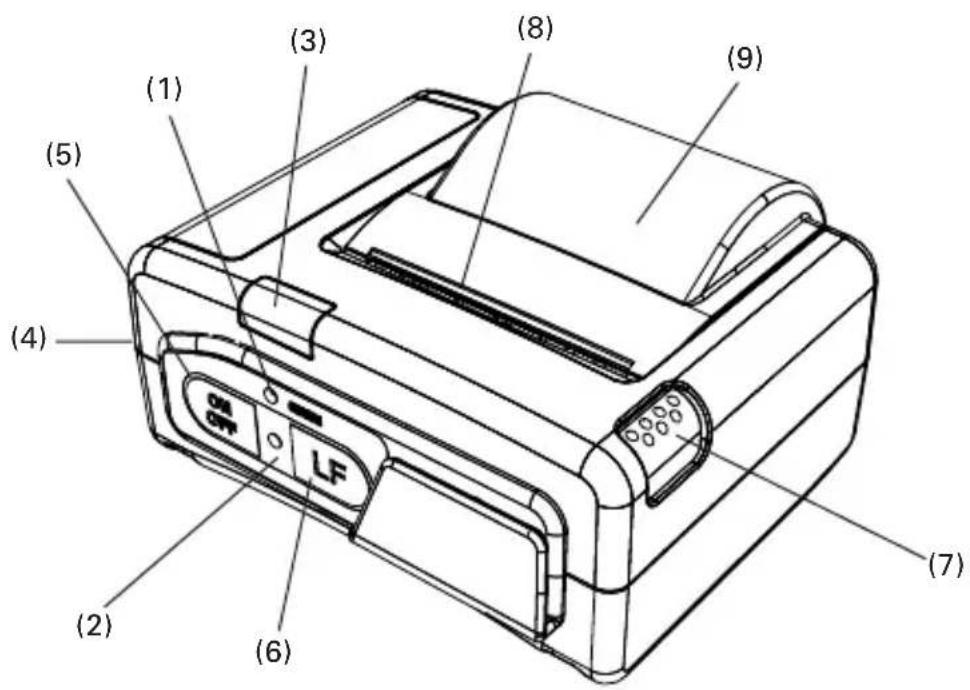
3. EXPLANATION OF PRINTER PARTS
RED on: Battery is charging
GREEN on: Battery is Fully charged
(2) Power (Error) LED
GREEN on: Lights when printer is powered ON.
RED/GREEN blinks fast: No paper or cover open.
RED/GREEN blinks slow: Print head is overheated or macro is in process and awaiting LF switch operation.
Red on: Lights red under the following condition.
- When LF switch is pressed
- When waiting for reading mag stripe card (When card reading is finished or after 10 seconds, it lights green.)
- While pressing and holding the Power switch to turn the printer off (When releasing the switch after the LED changes to green, the printer power is turned OFF.)
The LED will light red momentary at the time of IrDA communication.
3.2 Communication Port and Switch
(3) IrDA interface unit
Receives data from host and transmits printer status.
For communication with IrDA communication, refer to 4.3.
(4) Serial port
For serial cable (option) connection to host.
For the method of communication with cable and connecting cable, refer to 4.4.
(5) Power switch (ON/OFF)
Press and hold the Power switch for 1 second to turn the printer power ON.
Toturn OFF the printer, press and hold the Power switch till the Power LED changes from red to green.
(6) Line feed switch (LF)
Press once for 1 line paper feed.
Press down and hold for continuous paper feed to any required length.
If print data still remains in the printer when printing is suspended due to no paper or the like, recover the printable condition and then press this switch to resume printing.
(7) Open cover switch
Press down to open the paper cover (9) for replacing the paper roll.
(8) Manual cutter
To cut the printed paper, gently pull the paper from the edge of the paper at the angle so that paper firmly contacts the manual cutter.
Improper direction of pull may result in poor cutting or excessive unwinding of paper, or opening the cover. In some case, characters may be destroyed at the first printing after the paper is cut.
(9) Paper cover
Set print paper inside this cover.
3.3 Inside of Paper Cover

text_image
(10) (11)(10) Paper feed roller Feeds paper through the printing mechanism.
(11) Printing (thermal) head Records print data on the thermal paper.
3.4 Buzzer
The built-in buzzer sounds in the following cases.
When low battery is detected (sounds 3 times)
When magnetic card was successfully read (sounds once)
When buzzer command is sent (the number of sounding times is controllable)
3.5 Bottom Surface and Battery Cover
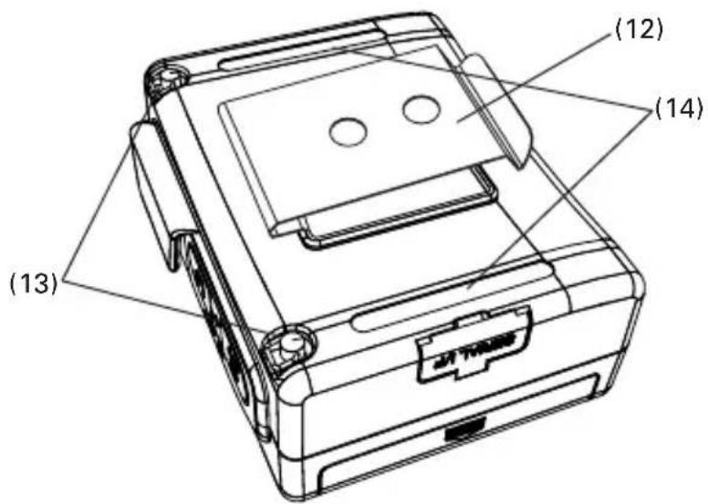
text_image
(12) (14) (13)(12) Belt clip
Attaches to the printer on your belt.
(Not installed at the time of shipment. To use the belt clip, please install the belt clip by yourself.)
(13) Strap holder
Metals for holding a strap.
(The strap shall be prepared by the user.)
(14) Groove for rubber foot
If you want to use rubber feet for stationary use, attach rubber feet here.
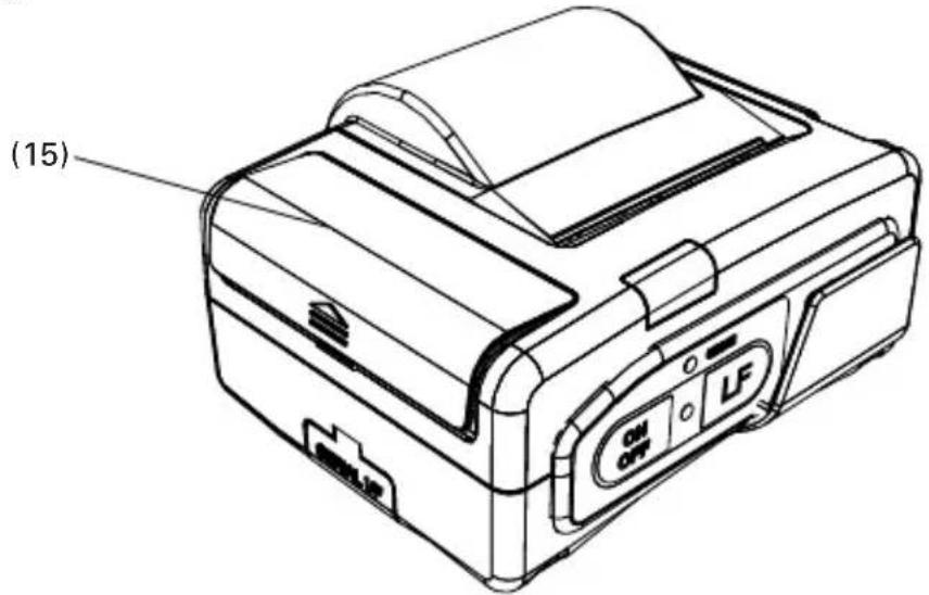
text_image
(15)(15) Battery cover
Cover of battery compartment
3.6 Dimensions and Views
(Unit: mm)
4. OPERATION
4.1 Replacing the Paper Roll
Press Cover Open switch (1).
Open Paper Cover (2).
Place the new paper roll as shown on illustration and pull out enough paper to reach the control panel of the printer (3).
Close the Paper Cover.
If data to be printed still exists, press the LF switch to resume printing.
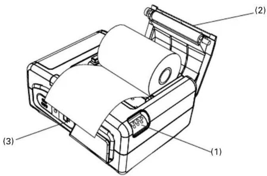
text_image
(1) (2) (3)
CAUTION!
Be sure to use specified thermal paper rolls!
Make sure that the paper is correctly placed.
If print paper is tilted in one direction or another and does not come out straight from under the cover, open the cover and set the paper roll again.

WARNING
When the paper cover is open, use care not to touch the print head or manual cutter. Burn or cutting hand may result.
4.2 Method of Charging
If any of the following conditions occur, charging the battery is required.
- "Low Battery" is printed.
• The buzzer sounds 3 times.
To charge the battery, plug the connector of the AC adapter to the DC jack of the printer and the AC adapter to the AC outlet. The charge LED lights red. If the LED changes to green, charging has completed.
In case of a trouble while charging the battery, the charge is suspended with blinking of charge LED in red. Try unplugging and plugging AC adapter, then charge should resume and charge LED changes to continue to light red.

CAUTION!
- Charge the battery at room temperature (5 - 35°C).
• After completion of battery charging, do not try recharging. Battery performance may be deteriorated. - If printer is kept used with recharging battery, the life of battery may be shortened.
- After completion of battery charging, if the AC adapter is kept connected, charging battery does not restart automatically even the battery level becomes low. To restart charging battery, condition of charging battery needs to be stopped by the way such as disconnecting AC adapter from AC inlet or disconnecting AC adapter from DC jack.
- When the battery is used in a cold environment, the operation time may be shortened.
- If the operation time is excessively shortened even after full charging, battery life may be assumed.
4.3 Communication by IrDA
For IrDA communication, DIP switch setting needs to be set for IrDA. Set the infrared port of the device to face straight to the printer's infrared port.
Communication is available in the range of 15^ up, down, left, and right.
Avoid blocking between the printer and the device to be connected.
Otherwise, data may not be sent correctly.

text_image
Max. length 80 cm Left, Right, Top, Bottom 15° The IrDA beam
CAUTION!
- Communication in a place exposed to strong light such as direct sunlight and fluorescent lighting may fail in receiving correct data.
- Communication may fail in receiving correct data after leaving the printer unused for a long time in other than storage temperature.
- The range of communication may differ depending on the device used or the environmental condition.
(Communication may be disabled even within the range given in the specification.)
4.4 Communication Via Serial Port (Cable)
For communication via serial (RS-232C) interface, use Citizen CA10-01 serial cable.
When the printer is OFF, open the serial port rubber cover and while holding the connector with the "PUSH" sign facing upward, gently insert the connector into the serial port.
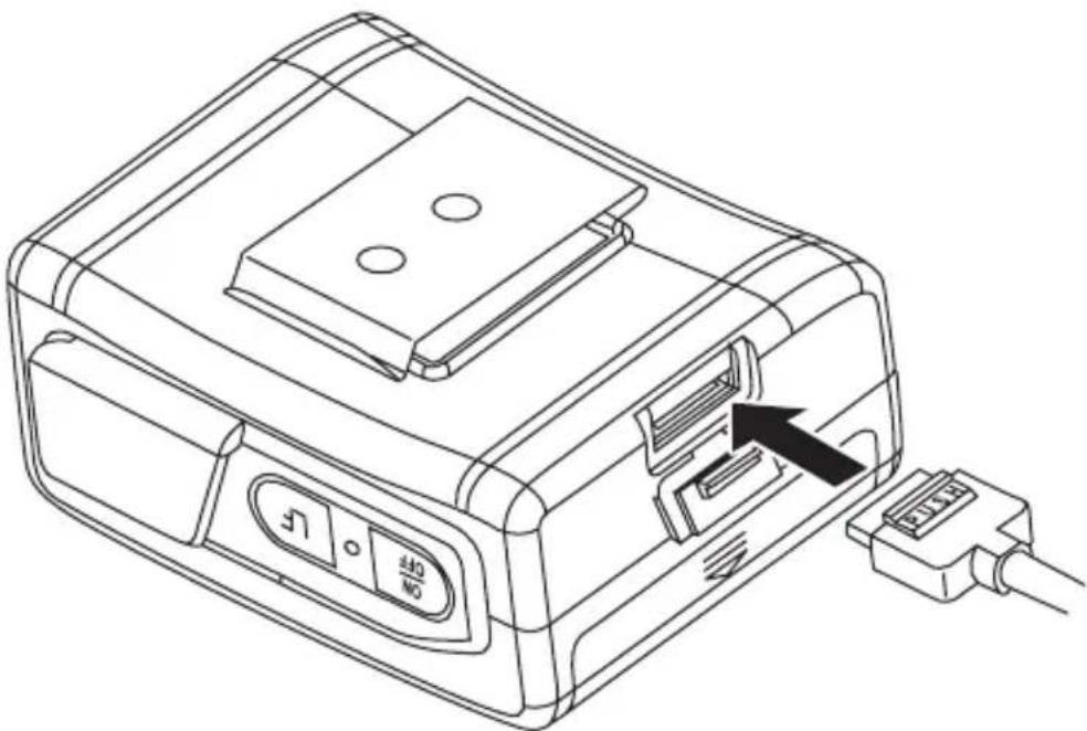
natural_image
Line drawing of a device with an attached cable and a black arrow pointing to a connector (no text or symbols present)Connect the other end of the cable to the device to be connected.
To disconnect serial cable from the printer firmly press "PUSH" sign on the connector and remove it from the serial port.
Push serial port rubber cover back into the serial port till it fits in firmly.

CAUTION!
If the cable is connected with Power ON, turn the Power OFF once and then turn the Power ON again to activate the connection with serial cable.
Set the flow control setting of the device to be connected to Xon/Xoff. In case of hardware control (DTR/DSR control), the Power switch may become disabled.
4.5 Communication by Bluetooth
For the Bluetooth communication, it is necessary to choose CMP-10BT and set the DIP switches for Bluetooth.
As built-in Bluetooth module supports Serial Port Profile, host machine needs to communicate with CMP-10BT based on serial port profile. Please refer to the software manual of the host machine for the details. When CMP-10BT connects through the Bluetooth interface, the host machine may require a pin code. The last 4 characters of the Bluetooth Address that prints on the printer self test are the pin code that should be entered in to the host machine.
4.6 Reading Mag Stripe Card (Only Model with Built-in Mag Stripe Card Reader)
To read the mag stripe card, it is necessary to send a special command to the printer.
For the command, refer to Command Reference supplied separately. If mag stripe card command is entered, Power LED lights red.
While the Power LED continues to light for 10 seconds, swipe the card be read during that time.
If 10 seconds has passed or reading is completed, the printer returns to normal mode.
Slide the card with the magstriped surface down to pass the magstripe over the reader part.
When reading has completed, buzzer sounds momentarily and Power LED changes to green.
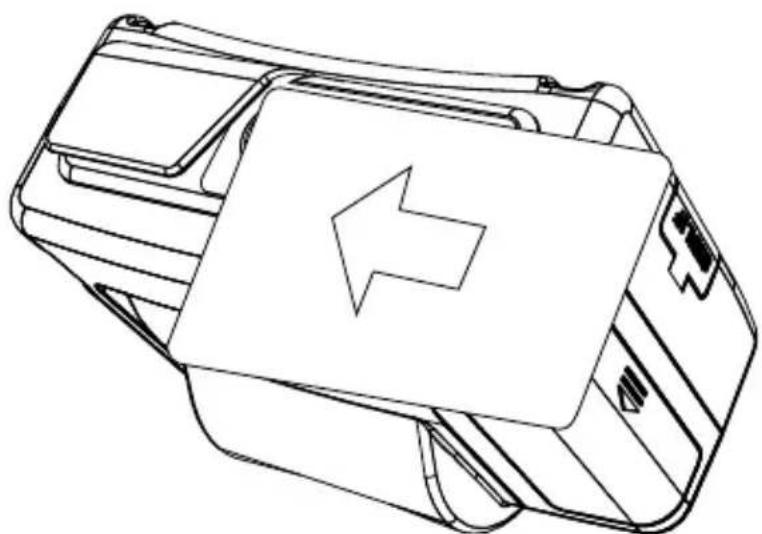
natural_image
Line drawing of a device casing with an arrow indicating leftward movement (no text or symbols)4.7 DIP Switch Setting
Either Bluetooth or IrDA function of CMP-10BT have to be chosen by DIP switches.
DIP switches are located under the battery.

text_image
OFF ON No.1 —— No.2 ——Function allocation of DIP switch is as follows.
| No. 1 No. 2 | ||
| Bluetooth ON ON *ON OFFOFF ON | ||
| IrDA OFF OFF | ||
* Default setting of CMP-10BT
There are no "No. 1", "No. 2", "ON" or "OFF" signs on actual case like the above drawing.
Standard CMP-10 does not have Bluetooth function and has no DIP switches.

CAUTION!
- Do not remove the battery cover or do not replace the battery by yourself. If you think that battery replacement will be necessary, contact our sales representative.
4.8 Setup menu function (Firmware after Ver 2.20EN)
Make sure the printer power is off. Press ON/OFF switch and keep pressed for about 5 seconds until .LED is changed to red and leave the switch. Then buzzer beeps and printer prints current setting and goes to setup menu as follows.
Example
DISCOVERABILITY: YES
PAIRING INFO SAVING: YES
MEMORY SWITCHES: 00000000
BAUD RATE: 9600
POWER OFF TIME: 10 min
PRINT DENSITY: 100%
MAX IrDA SPEED 57600: NO
SETUP MENU<ON/OFF> - NO, <LF> - YESCHANGE DISCOVERABILITY ?
The setting can be done by choosing NO (ON/OFF switch) or YES (LF switch) against coming up questions.
During the menu setting, if YES is chosen somewhere, following question comes up at the end of setup menu
SAVE SETTINGS ?
If you want to save the changed setting, choose YES here and if not, choose NO.
If YES is not chosen, the new setting will not be effective.
Setup menu ends with Power off in any case.
The list of choice in the setup menu
(Bold items is default value.)
| Top question items | Additional questions | YES (LF Switch) | NO (ON/OFF Switch) |
| CHANGE DISCOVERABILITY ? | SET DISCOVERABILITY ON ? | Discoverability ON | Discoverability OFF |
| CHANGE PAIRING INFO SAVING ? | PAIRING INFO SAVING ON ? | Enable Pairing Info Saving | Disable Pairing Info Saving |
| CHANGE MEMORY SWITCHES ?(See the table below) SET SWIT | SET SWITCH 1 ? Memory switch 1 = 1 Memory switch 1 = 0CH 2 ? Memory switch 2 = 1 Memory switch 2 = 0SET SWITCH 3 ? Memory switch 3 = 1 Memory switch 3 = 0SET SWITCH 4 ? Memory switch 4 = 1 Memory switch 4 = 0SET SWITCH 5 ? Memory switch 5 = 1 Memory switch 5 = 0SET SWITCH 6 ? Memory switch 6 = 1 Memory switch 6 = 0SET SWITCH 7 ? Memory switch 7 = 1 Memory switch 7 = 0SET SWITCH 8 ? Memory switch 8 = 1 Memory switch 8 = 0 | ||
| CHANGE BAUD RATE ? 1200 bps ? Baud rate 1200 bps2400 bps ? Baud rate 2400 bps4800 bps ? Baud rate 4800 bps9600 bps ?Baud rate 9600 bps19200 bps? Baud rate 19200 bps38400 bps? Baud rate 38400 bps57600 bps? Baud rate 57600 bps115200 bps? Baud rate 115200 bps | Not choose this baud rate | ||
| CHANGE AUTO POWER OFF 5TIME ? | min ?Auto power off 5 min10 min ?Auto power off 10 min15 min ?Auto power off 15 min20 min ?Auto power off 20 min25 min ?Auto power off 25 min30 min ?Auto power off 30 min45 min ?Auto power off 45 min60 min ?Auto power off 60 min | Not choose this time length | |
| CHANGE PRINT DENSITY ? | 70 % ?70 % ?80 % ?90 % ?100 % ?120 % ?150 % ? | 70 % density80 % density90 % density100 % density120 % density150 % density | Not choose this density |
| CHANGE IrDA MAX SPEED ? | LIMIT SPEED TO 57600 bps ? | IrDA Max speed 57600 bps | IrDA Max speed 115200 bps |
"CHANGE DISCOVERABILITY ?" and "CHANGE PAIRING INFO SAVING ?" are shown when Bluetooth function is available.
Memory switches
| Item | OFF(0) | ON(1) | |
| 1 | Shape of zero | With slash | No slash |
| 2 | CR code | Ignored | Works as LF |
| 3 | Default font | Font A | Font B |
| 4 | Print “Low Battery” | Valid | Invalid |
| 5 | Auto Status Back | Invalid | Valid |
| 6 | Not defined | - | - |
| 7 | IrDA Protocol | Valid | Invalid(Not recommended) |
| 8 | No use | - | - |
5. FUNCTION
5.1 Auto Power OFF
Power is automatically cut off after a specified period of time, during which no command is sent to the printer and the LF switch has not been pressed.
The default setting of this time duration is 10 minutes, however, the period can be custom set by the user with a special command to the printer. (see Command Reference List)
The behavior of the printer at the operation of Auto Power OFF is the same as that when power is turned OFF by the Power switch.
5.2 Interface Selection
The interface is automatically selected depending on the presence or absence of connection to the serial port with a serial cable connector.
- At POWER ON, no cable is connected, the IrDA/Bluetooth interface is selected.
●At POWER ON, the cable is connected, the Serial interface is selected.

CAUTION!
If cable is connected with printer power ON, selecting IrDA/Bluetooth interface remains valid. If you want to use the serial interface, turn the printer power OFF once, connect the serial cable, and then turn the printer power ON again.
5.3 Low Battery Detection
Battery charge level is monitored at Power ON, before paper feeding, and before printing.
When the buzzer sounds three times or "Low Battery" is printed, immediately charge the battery.
5.4 Monitoring the Print Head Overheating
If the temperature exceeds 65^ C for some reason, the printer automatically stops printing with Power LED indication of “Error” to protect the print head.
If the head temperature returns to 60^ C or below, the printer is ready for printing.
5.5 Self Testing and Internal Settings
- Keep the LF switch pressed down.
●Press the ON/OFF switch down.
●Release the ON/OFF switch.
●Release the LF switch.
Immediately after releasing the LF switch the printer will print out a SELF TEST report.
At the end of the report, density, auto-power off time, head temperature, battery output voltage, communication mode, baud rate (for serial communication) are printed.
The number of marks * in the parentheses aside battery output voltage shows a level of battery charge in 5 steps.
5.6 Print Area

text_image
4 mm Paper width - 58 mm Print area - 48 mm 6 mm Print area Thermal paper6. LIST OF COMMANDS
| 1 BEL Sounds the Buzzer | |
| 2 H T Horizontal Tab Command | |
| 3 L F Printing and Paper Feed Command | |
| 4 C R Print one line Command | |
| 5 ESC RS Sounds the Buzzer | |
| 6 ESC SP Setting the right space amount of the character | |
| 7 ESC ! Collective Specifying Printing Mode | |
| 8 ESC Specifying the Absolute Positions | |
| 9 ESC % Specifying/Canceling Download Character Set | |
| 10 ESC & Define user characters | |
| 11 ESC * Specifying the Bit Image Mode | |
| 12 ESC + Switch OFF the printer | |
| 13 ESC - Specifying/ Canceling Underline | |
| 14 ESC . Printer self test | |
| 15 ESC 2 Specifying 1/6-inch line feed rate | |
| 16 ESC 3 Setting line feed rate of minimum pitch | |
| 17 ESC = Data Input Control | |
| 18 ESC > Saving current setting | |
| 19 ESC ? Reading magnetic stripe reader | |
| 20 ESC @ Initializing the Printer | |
| 21 ESC D Setting Horizontal Tab Position | |
| 22 ESC E Specifying/canceling highlighting | |
| 23 ESC G Specifying/canceling Double Printing | |
| 24 ESC J Printing and feeding paper n/203 inch | |
| 25 ESC R Selecting Code table | |
| 26 ESC S Setting serial interface communication speed | |
| 27 ESC T Printing Diagnostic information | |
| 28 ESC V Specifying/Canceling 90°-right- turned Characters | |
| 29 ESC Y Specifying print density | |
| 30 ESC Z Returning diagnostic information | |
| 31 ESC Specifying the relative positions | |
| 32 ESC _ Setting the printer in default state | |
| 33 ESC ` Returning the battery voltage and Printer Head temperature | |
| 34 ESC a Aligning the characters | |
| 35 ESC c5 Enabling/Disabling | Panel Switches |
| 36 ESC d Printing and Feeding | the paper by n lines |
| 37 ESC v Transmitting the printer status | |
| 38 ESC x Selecting the time | interval for automatically switching Off the printer |
| 39 ESC Specifying/Canceling | the Inverted Characters |
| 40 G ) Setting of printer flags | |
| 41 G* Defining the Download | Bit Image (LOGO) |
| 42 G / Printing the Download | , Bit Image |
| 43 G: Starting/Ending Macro Definition | |
| 44 G H Selecting of Printing | Position of HRI Code |
| 45 GL Setting the left margin | |
| 46 G W Setting the print area width | |
| 47 G^ Executing the Macro | |
| 48 G a Enabling/Disabling | ASB (Automatic Status Back) |
| 49 Gf Selecting the font of | HRI characters |
| 50 G h Selecting the height | of the Bar Code |
| 51 Gk Printing the bar code | |
| 52 G w Selecting the horizontal size (Scale factor) of the Bar Code | |
| 53 G$ z Saving AT command | sequences to send to Bluetooth module |
| 54 ESC I Specify/canceling | black mark function |
| 55 FF Printing and paper feed | ding to the black mark position |
*
*
*
*
*
* indicates a unique command or a non-compatible command.
7. MAINTENANCE AND SERVICE
For the information on maintenance and service, please contact our dealer.
8. APPENDIX
HANDLING BELT CLIP KIT
This kit consists of a belt clip, two screws, and two rubber feet.
8.1 How to Mount Belt Clip
Mount the belt clip in the square frame using the two screws supplied. The direction of the belt clip should be as per the drawing below.
Note: Do not use screws without mounting the belt clip. The screws when mounted alone reach too deep and may come in contact with the internal circuit board and cause a failure.
8.2 Mounting Rubber Feet
Confirm that the grooves for the rubber feet are clean and neither dust nor oil is present on the grooves for rubber feet.
Peel off the liner sheet of the adhesive seal for rubber foot and carefully fit the rubber foot to the groove. Press and hold to secure the rubber foot.

text_image
Belt clip Grooves for rubber feetMEMO
WEEE MARK
En If you want to dispose this product, do not mix with general household waste. There is a separate collection systems for used electronics products in accordance with legislation under the WEEE Directive (Directive 2002/96/EC) and is effective only within European Union.