FOX 3G HD-SDI P SM - Wi-Fi repeater Extron - Free user manual and instructions
Find the device manual for free FOX 3G HD-SDI P SM Extron in PDF.

| Product Type | Wi-Fi Repeater / Range Extender |
| Brand | Extron |
| Model | FOX 3G HD-SDI P SM |
| Wireless Standard | IEEE 802.11 b/g/n |
| Frequency Band | 2.4 GHz |
| Maximum Wireless Speed | 300 Mbps |
| Security Encryption | WEP, WPA, WPA2 |
| Interface | 1 x 10/100 Ethernet Port (WAN/LAN) |
| Buttons | WPS, Reset |
| LED Indicators | Power, LAN, WLAN, Signal Strength |
| Power Supply | 5V DC, 1A |
| Power Consumption | < 5W |
| Dimensions (W x D x H) | 100 x 60 x 20 mm |
| Weight | 150 g |
| Operating Temperature | 0°C to 40°C |
| Mounting | Desktop or wall-mountable |
| Antenna | Internal dual-band antenna |
| Compliance | CE, FCC |
| Package Contents | FOX 3G HD-SDI P SM, Power Adapter, Ethernet Cable, Quick Start Guide |
Frequently Asked Questions - FOX 3G HD-SDI P SM Extron
User questions about FOX 3G HD-SDI P SM Extron
0 question about this device. Answer the ones you know or ask your own.
Ask a new question about this device
Download the instructions for your Wi-Fi repeater in PDF format for free! Find your manual FOX 3G HD-SDI P SM - Extron and take your electronic device back in hand. On this page are published all the documents necessary for the use of your device. FOX 3G HD-SDI P SM by Extron.
USER MANUAL FOX 3G HD-SDI P SM Extron
This guide provides instructions for an experienced installer to set up and operate Extron® FOX 3G HD-SDI Transceiver.
The transceiver can be configured via its rear panel Mode DIP switches to operate in one of three ways:
• Bidirectional transceiver
- Transmitter
- Receiver

See Transceiver Configurations on the rear of this guide if you need more information.
NOTE: In this guide, the term "transceiver" refers to any FOX 3G HD-SDI; the term "bidirectional transceiver" refers to a FOX 3G HD-SDI specifically configured as a bidirectional transceiver.
Installation
Step 1 — Mounting
Turn off or disconnect all equipment power sources and mount the transceiver as required.
Step 2 — Connections and Initial Settings
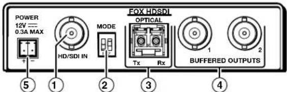
① HD-SDI Input connector — If the FOX 3G HD-SDI is configured as either a bidirectional transceiver or as a transmitter, connect an HD-SDI, SDI, or 3G-SDI video input to this BNC connector.
② Mode switches — Set these DIP switches to the positions shown at right to select the transceiver configuration. See Transceiver Configurations on the rear of this guide for more information.
③ Fiber optic connectors —
| SW1 | SW2 | Mode |
| Down | Down | Bidirectional transceiver (default position) |
| Down | Up | Transmitter with local monitor outputs |
| Up | Down | Receiver with daisy chaining |
| Up | Up | Spare (functions as receiver with daisy chaining) |
WARNING: This unit outputs continuous invisible light, which may be harmful to the eyes; use with caution. For additional safety, plug the attached dust caps into the optical transceivers when the fiber optic cable is unplugged.
NOTE: Ensure that you use the proper fiber cable for your transceivers. Typically, singlemode fiber cable has a yellow jacket and multimode fiber cable has an orange or aqua jacket.
Tx connector — In any configuration, connect a fiber optic cable to the Optical Tx LC connector.
Connect the free end of this fiber optic cable to the Optical Rx connector on another FOX 3G HD-SDI transceiver that is configured as a bidirectional transceiver or as a receiver.
Rx connector — In either the bidirectional transceiver or receiver configuration, connect a fiber optic cable to the Optical Rx connector to receive the signal from the transmitting unit. Connect the free end as detailed below:
- In a 2-transceiver system, connect the free end of this cable to the Optical Tx connector on the transmitting unit, which is configured as a transmitter.
- In a daisy-chained system, connect the free end of this cable to the Optical Tx connector on the previous unit in the daisy chain (configured as either a bidirectional transceiver or a transmitter).
④ Buffered Outputs connectors — In any FOX 3G HD-SDI configuration, connect a digital display to these BNC connectors.
In the bidirectional transceiver configuration, connectors 1 and 2 both output the video that is sent from the other transceiver.
In the receiver configuration, only connector 2 outputs video and it is the video sent by the transmitting unit.
In the transmitter configuration, connectors 1 and 2 both output the video signal that is input on the HD/SDI Input connector, ①, on the same transceiver.
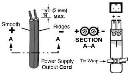
⑤ Power connector — Plug the included external 12 VDC power supply into this 2-pole captive screw connector as shown at right. Use the supplied tie-wrap to strap the power cord to the extended tail of the connector.
Operation
After the transmitting and receiving units and all of their connected devices are powered up, the system is fully operational. If any problems are encountered, ensure all traditional and fiber cables are routed and connected properly. If your problems persist, call the Extron S ^3 Sales & Technical Support Hotline that is closest to you, at the number shown below.
Fiber Compatibility Indications
Use the proper fiber cable for your transceivers. Each transceiver indicates its fiber compatibility, singlemode or multimode, at power-up by blinking the four front panel Rate indicators, once for multimode or twice for singlemode.
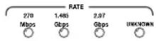
NOTE: All transceivers in the system must be the same model (either all singlemode or all multimode). Mixed transmission mode units will not work together.
Transceiver Configurations
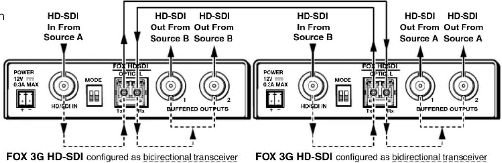
Bidirectional Transceiver
A bidirectional transceiver inputs digital video on its SDI/HD-SDI Input BNC. The transceiver converts the video input to a proprietary signal and transmits it over a fiber link to another FOX 3G HD-SDI that is configured as either a bidirectional transceiver or as a receiver.
A bidirectional transceiver can also simultaneously receive a proprietary signal from another transceiver (in any configuration) on its Optical Rx port, convert the proprietary signal back to the original format digital video, and output the video on its own two Buffered Outputs BNC connectors.
flowchart
graph TD
    subgraph_HD-SDI_Configuration1["HD-SDI In From Source A"]
        A1["POWER 12V --- 0.3A MAX"] --> A2["HD/SDI IN"]
        A2 --> A3["MODE"]
        A3 --> A4["Tx1"]
        A4 --> A5["Rx"]
        A5 --> A6["BUFFERED OUTPUTS"]
    end

    subgraph_HD-SDI_Configuration2["HD-SDI In From Source B"]
        B1["POWER 12V --- 0.3A MAX"] --> B2["HD/SDI IN"]
        B2 --> B3["MODE"]
        B3 --> B4["Tx1"]
        B4 --> B5["Rx"]
        B5 --> B6["BUFFERED OUTPUTS"]
    end

    A1 --> A4
    A2 --> A4
    A3 --> A4
    A4 --> A5
    A5 --> A6
    B1 --> B4
    B2 --> B5
    B3 --> B6
    B4 --> B6
    B5 --> B6
    B6 --> B7["Buffered OUTPUTS"]
    B7 --> B8["Buffered OUTPUTS"]
    style HD-SDI Configuration1 fill:#f9f,stroke:#333
    style HD-SDI Configuration2 fill:#f9f,stroke:#333
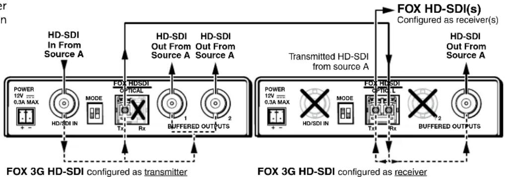
Transmitter and Receiver
A unit configured as a transmitter inputs digital video on its HD/SDI Input BNC. The transmitter converts the video input to a proprietary signal and transmits the video over a fiber link to a FOX 3G HD-SDI that is configured as a receiver or as a bidirectional transceiver. The transmitter also simultaneously outputs the digital video on its two Buffered Outputs BNCs.
A unit configured as a receiver accepts a proprietary signal on its Rx fiber optic port.
The receiver converts the proprietary signal back to original HD-SDI, SDI, or 3G-SDI video and outputs the video on only one of its own Buffered Output BNC connectors, Output 2.
The receiver converts the second digital video signal that it created from the optical input back into a proprietary signal and outputs it on the Optical Tx port over a fiber link to another FOX 3G HD-SDI that is configured as a receiver or as a bidirectional transceiver.
flowchart
graph TD
    subgraph_HD_SDI_Configuration1["FDX 3G HD-SDI configured as transmitter"]
        direction TB
        A1["POWER 12V = 0.3A MAX"] --> B1["HD/SDI IN"]
        B1 --> C1["MODE"]
        C1 --> D1["Tx"]
        D1 --> E1["Rx"]
        E1 --> F1["BUFFERED OUTPUTS"]
    end
    subgraph_HD_SDI_Configuration2["FDX 3G HD-SDI configured as receiver"]
        direction TB
        A2["POWER 12V = 0.3A MAX"] --> B2["HD/SDI IN"]
        B2 --> C2["MODE"]
        C2 --> D2["Tx"]
        D2 --> E2["Rx"]
        E2 --> F2["BUFFERED OUTPUTS"]
    end
    subgraph_Transmitted_HD_SDI_Configuration3["Transmitted HD-SDI from source A"]
        direction TB
        A3["POWER 12V = 0.3A MAX"] --> B3["HD/SDI IN"]
        B3 --> C3["MODE"]
        C3 --> D3["Tx"]
        D3 --> E3["Rx"]
        E3 --> F3["BUFFERED OUTPUTS"]
    end
    subgraph_HD_SDI_Configuration4["FDX HD-SDI(s) Configured as receiver(s)"]
        direction TB
        A4["POWER 12V = 0.3A MAX"] --> B4["HD/SDI IN"]
        B4 --> C4["MODE"]
        C4 --> D4["Tx"]
        D4 --> E4["Rx"]
        E4 --> F4["BUFFERED OUTPUTS"]
    end
NOTE: Up to 10 receivers can be daisy-chained in this manner.
| Extron USA - West Headquarters | Extron USA - East | Extron Europe | Extron Asia | Extron Japan | Extron China | Extron Middle East |
| +800.633.9876Inside USA/Canada Only | +800.633.9876Inside USA/Canada Only | +800.3987.6673Inside Europe Only | +800.7339.8766Inside Asia Only | +81.3.3511.7655+81.3.3511.7656 FAX | +400.883.1568Inside China Only | +971.4.2991800+971.4.2991880 FAX |
| +1.714.491.1500+1.714.491.1517 FAX | +1.919.863.1794+1.919.863.1797 FAX | +31.33.453.4040+31.33.453.4050 FAX | +65.6383.4400+65.6383.4664 FAX | +86.21.3760.1568+86.21.3760.1566 FAX |
68-1384-50
Rev A
07 10