FOXBOX Tx DVI Plus MM - Wi-Fi repeater Extron - Free user manual and instructions
Find the device manual for free FOXBOX Tx DVI Plus MM Extron in PDF.

User questions about FOXBOX Tx DVI Plus MM Extron
0 question about this device. Answer the ones you know or ask your own.
Ask a new question about this device
Download the instructions for your Wi-Fi repeater in PDF format for free! Find your manual FOXBOX Tx DVI Plus MM - Extron and take your electronic device back in hand. On this page are published all the documents necessary for the use of your device. FOXBOX Tx DVI Plus MM by Extron.
USER MANUAL FOXBOX Tx DVI Plus MM Extron
This card provides quick start instructions for an experienced installer to set up and operate an Extron® FOXBOX DVI Plus transmitter and receiver.
NOTES: • Only the FOXBOX Rx DVI Plus receiver can accept input from a FOXBOX Tx DVI Plus transmitter.
- The FOXBOX Rx DVI Plus receiver can accept inputs from any FOX 500 or FOXBOX transmitter, including VGA models.

Installation
Step 1 — Mounting
Turn off or disconnect all equipment power sources and mount the transmitter and receiver as required.
Step 2 — Input and Output Connections
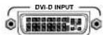
a. Connect a DVI video source to the to the Input connector on the transmitter and the a DVI Display to the Output connectors on the receiver.
b. Connect unbalanced stereo or mono audio input and an audio output device to the 3.5 mm mini jack audio ports on both units.

c. If you want the FOXBOX units to pass serial data or control signals, such as for serial control of a projector, connect the master device to the transmitter and the slave device using the first three poles of the RS-232 Over Fiber/Alarm 5-pole captive screw connectors on both units.

NOTE: For RS-232 responses (from the receiver to the transmitter), you must install the cable in step 3b and leave the receiver in normal configuration.
d. For remote monitoring of the status of the optical links, connect a locally constructed or obtained device to the two Alarm poles of the units' RS-232 Over Fiber/Alarm 5-pole captive screw connectors. The two poles are shorted together when no light is detected.

NOTES: The Alarm port on the transmitter reports the status of the Rx light link. The Alarm port on the receiver reports the status of the Tx light link.
Step 3 — Throughput Connections
NOTE: You can connect the transmitter and one or more receivers in one of three ways:
• One way (transmitter to receiver) only, perform step 3a.
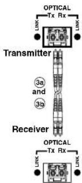
• Two way (transmitter to receiver and return), perform steps 3a and 3b.
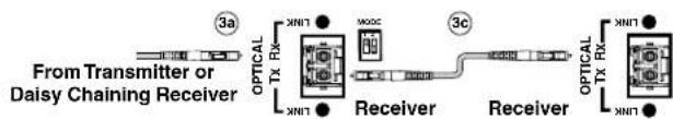
• One way (transmitter to receiver) with daisy chain (receiver to receiver), perform steps 3a and 3c.
a. Connect a fiber cable between the Tx port on the transmitter and the Rx port on the receiver.
b. If you want the receiver to send return serial data (such as responses from a controlled device) to the transmitter, connect a fiber cable between the Tx port on the receiver and the Rx port on the transmitter.
c. If you want a receiver to daisy chain the optical signal to another receiver (up to 10 receivers in a daisy chain):
- Connect the Tx port on the receiver to the Rx port on another receiver.
- Set the Mode DIP switch 1 up on first receiver.
flowchart
graph LR
    A["From Transmitter or Daisy Chaining Receiver"] --> B["Receiver"]
    B --> C["Receiver"]
    C --> D["Optical TX RX"]
    D --> E["XNIT"]
    E --> F["MOSC"]
    F --> G["3a"]
    C --> H["Optical TX RX"]
    H --> I["XNIT"]
Step 4 — Remote Connector
Connect a host device to either unit's front panel Configuration connector via the 9-pin D to 2.5 mm mini jack TRS RS-232 cable that is included with the TX model or available separately using part #70-335-01. Refer to the FOXBOX DVI Plus User Guide for detailed information about the using the Simple Instruction Set (SIS™) commands and the Windows®-based FOX Extender program to set up and operate the transmitter and receiver and to take advantage of the various adjustments and test patterns available on the FOXBOX units.
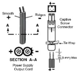
Step 5 — Power
Connect using an external power supply as shown on the right.
Control and Indications
Operation
After all receivers, the transmitter, and their connected devices are powered up, the system is fully operational. If any problems are encountered, verify that the cables are routed and connected properly and that all display devices have identical resolutions and refresh rates. If your problems persist, call the Extron S ^3 Sales & Technical Support Hotline.
Mode Switch
Mode switch (receiver) — To connect the received optical input to another receiver in a daisy chain configuration, set DIP switch 1 to up as shown.

DIP switch 2 is not used.
NOTE: Up to 10 properly-configured receivers can be connected in a daisy chain to a single transmitter.
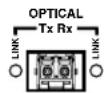
Indications
Tx Link and Rx Link LEDs — When lit, the link is active (light is output [Tx] or received [Rx]).
NOTE: The Link LEDs indicate light transmission only, not whether there is data encoded in the optical link.
Power LED — This LED lights to indicate that power is applied to the unit.
Over Temp(erature) LED — This LED lights to indicate that the unit is operating at a dangerously high temperature (approximately 167^ F [ 75^ C]) and that equipment damage is imminent.
DVI LED — This LED lights on both units when the transmitter detects a signal on its video input. This LED lights on the receiver when the transmitter detects a DVI video signal.
Audio LED — This LED lights on both units when the transmitter detects a low level audio signal for a short period of time. It goes dark if the audio signal drops below the minimum threshold for a short period of time.
| Extron USA - West Headquarters | Extron USA - East | Extron Europe | Extron Asia | Extron Japan | Extron China | Extron Middle East |
| +800.633.9876Inside USA/Canada Only | +800.633.9876Inside USA/Canada Only | +800.3987.6673Inside Europe Only | +800.7339.8766Inside Asia Only | +81.3.3511.7655+81.3.3511.7656 FAX | +400.883.1568Inside China Only | +971.4.2991800+971.4.2991880 FAX |
| +1.714.491.1500+1.714.491.1517 FAX | +1.919.863.1794+1.919.863.1797 FAX | +31.33.453.4040+31.33.453.4050 FAX | +65.6383.4400+65.6383.4664 FAX | +86.21.3760.1568+86.21.3760.1566 FAX |