TV-IP612P - Security Camera TRENDNET - Free user manual and instructions
Find the device manual for free TV-IP612P TRENDNET in PDF.


| Product Type | Security Camera (IP Bullet) |
| Brand | TRENDnet |
| Model | TV-IP612P |
| Image Sensor | 1/2.9" Progressive CMOS |
| Resolution | 1920 x 1080 (2 Megapixel) |
| Lens | 3.6mm fixed lens, F1.8 |
| Night Vision | Up to 30 meters (98 ft) with IR LEDs |
| Video Compression | H.264 / MJPEG |
| Network Interface | 10/100 Mbps RJ-45 with PoE (802.3af) |
| Power Supply | PoE (802.3af) or 12V DC, 1A |
| Power Consumption | Maximum 6.5W |
| Weatherproof Rating | IP66 (outdoor use) |
| Dimensions (approx.) | 191 x 82 x 82 mm (7.5 x 3.2 x 3.2 in) |
| Weight (approx.) | 560 g (1.2 lb) |
| Operating Temperature | -20°C to 50°C (-4°F to 122°F) |
| Motion Detection | Built-in, with email and FTP alerts |
| Mobile App Support | Yes (TRENDnetView Pro or similar) |
| Maintenance & Cleaning | Clean lens with soft, dry cloth; avoid solvents |
| Safety Precautions | Use only supplied power adapter; ensure proper grounding |
| Repairability & Spare Parts | Contact TRENDnet support for service; no user-serviceable parts |
Frequently Asked Questions - TV-IP612P TRENDNET
User questions about TV-IP612P TRENDNET
0 question about this device. Answer the ones you know or ask your own.
Ask a new question about this device
Download the instructions for your Security Camera in PDF format for free! Find your manual TV-IP612P - TRENDNET and take your electronic device back in hand. On this page are published all the documents necessary for the use of your device. TV-IP612P by TRENDNET.
USER MANUAL TV-IP612P TRENDNET
natural_image
Two white wireless camera devices with visible sensor and antenna, no text or symbols present.User's Guide
TV-IP612P
TV-IP612WN
1.02
ABOUT THIS USER'S GUIDE .... 1
INTRODUCTION 2
Features and Benefits....2
Unpacking the Package .... 3
System Requirements 4
Default Settings 5
Camera Hardware Components 6
Front Panel Components.... 6
LED Indicators....6
Rear Panel Components 7
INSTALLING THE CAMERA....9
Attach the Metal Plate 9
Connect Ethernet Cable 10
Connect Power and Power On Camera.... 10
Reset Camera 11
SECURITY 12
APPLICATION....13
USING THE UTILITY 14
SetupWizard 14
USING THE CAMERA WEB MANAGER....30
Accessing the Camera Video Display 30
Login 31
Setup - Web Configuration Utility 31
Wizard 32
Step 1 Setup LAN Settings.... 33
Step 2 Setup Internet Settings 33
Step 3 Setup DDNS Settings 34
Step 4 Camera Name Settings.... 34
Step 5 Setup Time Zone 35
Step 6 Setup Complete 35
System 36
Device Management 36
Time and Date 37
Network 38
Network Setup 38
Port Settings 39
Wireless Setup 39
Selecting a SSID from the Site Survey.... 40
Dynamic Domain Name Service (DDNS) 40
Video Audio 41
Video and Audio....41
Video Profile 1-4....41
Audio Setup 42
Image Setup 42
ICR 44
Action 45
Recording 45
Recording Options 46
Scheduling 46
Snapshot 47
Email Settings 47
Preset Position 48
Camera Control 48
Digital Output 49
External Digital Input/Output Connectors 49
Trigger 50
Trigger Event 50
Motion Detection 51
Live Video 51
Drawing Mode: 51
Tools....52
Backup and Restore 52
Firmware Upgrade 52
Device Info....53
Device Info 53
Log....53
Viewing Video....54
Controlling the Camera....55
IPVIEW PRO 2.0 ....57
Launching IPView Pro 2.0 for the first time ....57
Add a camera for monitoring.... 58
IPView Pro 2.0 User Interface....60
Display Controls 61
Live video display controls 63
Camera configuration with IPView Pro 2.0 64
Adding a Camera – Camera management.... 64
Removing a Camera....65
Schedule Recording with IPView Pro 2.0....66
Setup Motion Detection and Digital Input with IPView Pro 2.0 68
IPView Pro 2.0 Recording Options....69
IPView Pro 2.0 Miscellaneous Options....70
PLAYING VIDEO FILES ON A COMPUTER....71
Load Saved Video Files....72
Play Video Files....73
ffdshow 74
APPENDIX 80
A. Frequently Asked Questions 80
B. PING your IP Address 82
C. Troubleshooting....84
D.Time Zone Table 89
E.Technical Specifications 92
About This User's Guide
This User Guide provides instructions on how to install the TV-IP612P/W Wireless Network camera and use it for camera monitoring applications. Camera monitor applications are accessible through an Ethernet or 802.11b/g/n wireless local area network. The following chapters are included in this User Guide:
• Chapter 1, Introduction, provides general information about the Camera.
- Chapter 2, Installing the Camera, describes the hardware installation procedure for the Camera.
• Chapter 3, Security, explains the security features of the Camera.
- Chapter 4, Application of the Camera, provides an illustration of the Camera's applications.
- Chapter 5, Using the Utility, guides you through configuring the Camera with the Utility.
- Chapter 6, Using the Camera Web Manager, guides you through configuring the Camera with a Web Browser.
• Chapter 7, IPView Pro, helps you to install and use the software.
- Chapter 8, Playing Video Files on a Computer, shows you how to use the IPCamPlayer application to record and play back video recordings with the Camera.
• Chapter 9, Appendix.
Please note that the illustrations or setting values in this manual are FOR YOUR REFERENCE ONLY. The actual settings and values depend on your system and network. If you are not sure about the respective information, please ask your network administrator or informations systems staff for help.
1
Introduction
Thank you for purchasing the TV-IP612P/TV-IP612WN Pan/Tilt/Zoom (Wireless) Internet Camera, a standalone system that can be connected directly to an Ethernet or Fast Ethernet connection. The TV-IP612WN also supports wireless transmissions based on the IEEE 802.11b/g/n standard. Compared to a conventional PC camera, the Pan/Tilt/Zoom Internet (Wireless) Camera features a built-in CPU and web-based solution that can provide a cost-effective way of transmitting real-time high-quality video images for monitoring. The Camera can be managed remotely, allowing you to use a Web browser to access the Camera from any notebook/desktop computer over an intranet or the Internet. The simple installation procedures and Web-based interface allows you to easily integrate the Camera into your network. With comprehensive application support, the Internet Camera is an ideal solution for remotely monitored, high quality and high performance video images.
Features and Benefits
Easy to use - The Camera is a standalone system with built-in CPU, no special hardware or software is required. The camera supports DirectX 9.0; therefore, the only requirement you need is the web browser software such as Internet Explorer 7.0 or above. Once you have a valid IP Address, just connect it and you can view video footage from your Camera. In addition, the Camera's pan/tilt/zoom function allows you to adjust the Camera for optimal viewing angles and zoom strength. You can pan the Camera to the left or right (-165° \~ +165°) and tilt the Camera up or down (-84° \~ +31°) using the Web Configuration Utility. Further, you can also zoom up to a maximum of 10x optical zoom.
Motion detection and event triggered digital image or video recording – Use the Motion Detection to take a snapshot or digital video record of objects that move through a selected area of the video display.
Supports variety of platforms - The camera supports TCP/IP networking, SMTP e-mail, HTTP and other Internet related protocols. It can be utilized in a mixed operating system environment, including Windows XP/Vista/7. Moreover, it can be integrated easily into other www/ Intranet applications.
Video Encoding The TV-IP612P/TV-IP612WN provides you with selectable video encoding formats that are able to efficiently utilize bandwidth. Using selectable video compression such as MJPEG, MPEG-4 and H.264 codecs, a reduction in bandwidth and storage space can be achieved. By using, for example, the H.264 codec over MJPEG of 80 percent is achievable.
Web configuration - Applying a standard web browser, the administrator can configure and manage the camera directly from its own web page via the Intranet or Internet. Up to 64 user accounts are permitted with privilege settings controlled by the administrator.
Remote Utility - The powerful IPView Pro 2.0 application assigns the administrator with a pre-defined user ID and password, allowing the administrator to modify the camera settings from the remote site via Intranet or Internet. When new firmware is available, you can also upgrade remotely over the network for added convenience. Users are also allowed to monitor the image, and take snapshots.
Broad Range of Applications - With today's high-speed Internet services, the Camera can provide the ideal solution for live video images over the Intranet and Internet for remote monitoring. The Camera allows remote access from a Web-browser for live image viewing and
allows the Administrator to manage and control the Camera from anywhere in the World at anytime. The Camera can be used to monitor many different objects and places, including homes, offices, banks, hospitals, child-care centers, amusement parks and all kinds of industrial and public monitoring tasks. The Camera can also be used to detect intruders, capture still images for archiving and many other applications.
Remote Surveillance The TV-IP612P/TV-IP612WN is 3GPP compatible or in other words it supports mobile surveillance where a live feed from the camera can be viewed on a compatible 3G cellular network connected phone or other smart cellular network device. The device must be capable of supporting Real Time Streaming Protocol (RTSP) to enable you to monitor your video feed from any remote location supporting 3G protocols.
Local A/V Output The TV-IP612P/TV-IP612WN is equipped with a A/V output which allows you to connect it directly to a TV or VCR to view or record the camera's video. The Audio from the A/V output jack can be connected directly to a local speaker inorder to provide audio to anyone within hearing range of the camera. This way a camera administrator can speak directly to anyone nearby the camera.
Input/Output Pins The camera supports industry standard input from the connection of various external devices including alarm relays, switches, and IR motion sensors. This can then further be associated with industry standard output to alarm devices that can be programmed based on the input triggers.
Multiple Protocol Support The camera further supports multiple protocol platforms such as: FTP, SMTP, NTP, HTTP, UPnP and DDNS.
Unpacking the Package
Open the shipping carton and carefully remove all items. Check that you have the following:
- One TV-IP612P or TV-IP612WN Internet Camera Server
- Two Detachable Antenna (TV-IP612WN only)
• One Multi-Language Quick Installation Guide
• One CD-ROM (Utility & User's Guide)
• One External Power Adapter (12V DC, 2A)
• One RJ-45 Ethernet Cable
• One Metal Mounting Plate - 2x M3 6mm Screws for screwing the Camera to the Metal Plate
- 5x M3 16mm Screws for mounting the Camera to a wall or ceiling
- Audio/Video Cable
If any packaging content is damaged or missing, please contact your local dealer immediately. Also, keep the box and packing materials in case future shipment is necessary.

CAUTION: The Camera must be used with the power adapter included with the device.
System Requirements
Networking
- Local Area Network: 10Base-T Ethernet or 100Base-TX Fast Ethernet
- Wireless Local Area Network: IEEE 802.11b/g/n Wireless LAN (TV-IP612WN only)
Computer
• CPU: P4 2.8GHz or above
• Memory: 512 MB or above
• VGA Resolution: 1024 x 768 or above (Independent Display Card recommended)
- Network Card
- For cabled connections: 10BASE-T Ethernet or 100BASE-TX Fast Ethernet Network Interface Card
-
For wireless connections: 802.11b/g/n series Wireless Interface Card
-
CD-ROM Drive for Setup Wizard on Installation CD-ROM
- IPView Pro 2.0 Application Users must use Microsoft® Windows® XP, Vista, and 7 Operating System with:
- Internet Explorer 6.0 or above with DirectX9.0 or
○ Mozilla Firefox and Apple Safari with Java Applet requires JVM (J2SE 1.5 or later, or JRE (J2SE) 6.0 or later).

NOTE: When you connect multiple cameras and monitor their images synchronously, it is recommended to use a high performance system, such as a Pentium 4 2.8GHz PC.
Default Settings
Use the default settings to access the web-based management software and live video display.
| Default configuration settings | |
| Username | This is the Username you will be prompted to enter when you access the TV-IP612P/WN configuration screens using a Web browser. The default Username is admin. |
| Password | This is the Password you will be prompted to enter when you access the configuration windows using a Web browser. The default Password is admin. |
| IP address | This is the IP address you will enter into the Address field of your Web browser to access the camera monitor screen and configuration menus using a Web Browser. The camera uses DHCP for IP settings by default. If a DHCP server is not detected, the default IP address is 192.168.10.30. (Make sure your computer is configured to belong to the 192.168.10.X subnet if using the default IP address of the camera.) |
| Subnet Mask | The default subnet mask is 255.255.255.0. |
Camera Hardware Components
This section provides information about the Camera's hardware components:
Front Panel Components
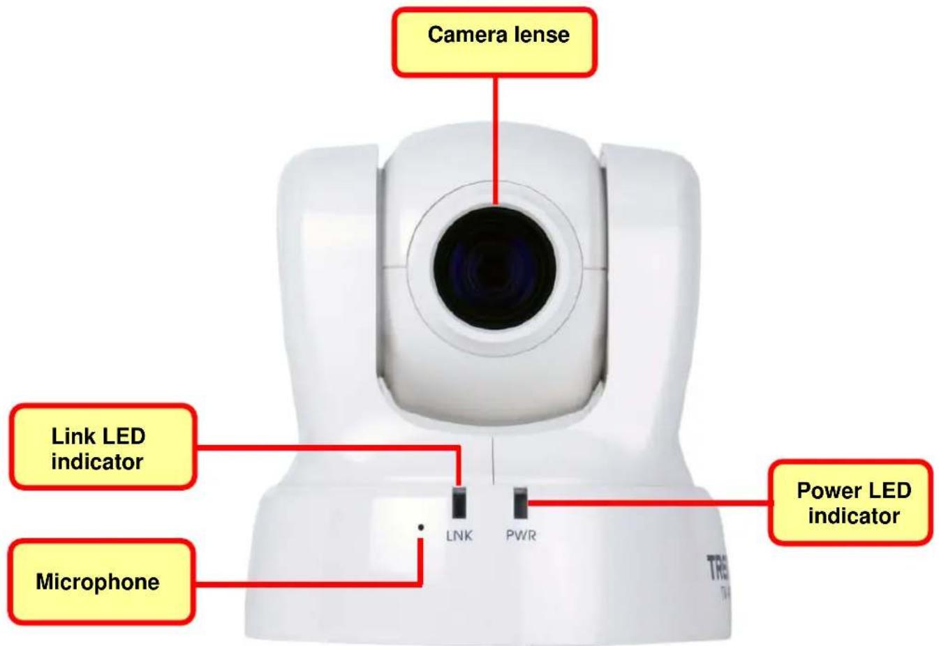
Front panel of TV-IP612P/W
LED Indicators
| LNK | This LED indicator lights steady orange when a valid Ethernet link is established. It blinks orange when traffic is received or transmitted through the Ethernet link. |
| PWR | This LED indicator lights blue when the camera is powered on. It remains dark when powered off. |
| Microphone | The microphone allows you to listen, from the monitoring computer, to the local audio near the camera. |
Rear Panel Components
The power connection to the camera when fitted with the Infrared lens is split between the camera body and lens using the power connection adapter cable attached to the infrared lens. All other cables connect to the camera at the rear panel.
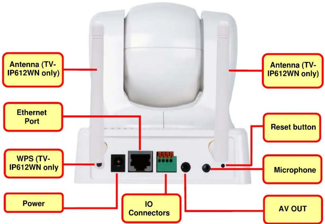
Rear Panel view of TV-IP612P/W
| WPS | Press this button to enable Wireless Protected Setup so that you can automatically connect with a WPS enabled wireless device such as a router or access point. |
| Power receptacle | Connect power adapter shipped with the camera and plug into suitable power source. |
| Ethernet Port | Connect to Ethernet LAN. The port is auto MDI-II/MDI-X and auto-negotiation for port speed. |
| IO Connectors | This terminal block has one input pair and one output pair of pins to connect external input/output devices. |
| AV Out / Speaker Out | Connect this Audio/Video output jack with the supplied cable so that you can view or record the live video feed on a local TV or VCR. You can also connect audio to a local speaker for local audio reproduction. |
| MIC | Used this jack to connect and record audio from an external microphone. |
| Reset Button | Use to reset device to factory default settings including IP address and administrator user name and password. |
| Antennas | A threaded post is used for attaching the antenna. Fasten the antenna securely to the post. |
2
Installing the Camera
The camera is intended for indoor use. The camera, the power adapter and power source should be protected from water and moisture, excessive heat, direct sunlight and cold. Make sure the power adapter and its cord and the Ethernet cable are safely arranged so they do not create a tripping hazard and will not be disturbed by people or objects moving past.
Attach the Metal Plate
To attach the metal plate carry out the following:
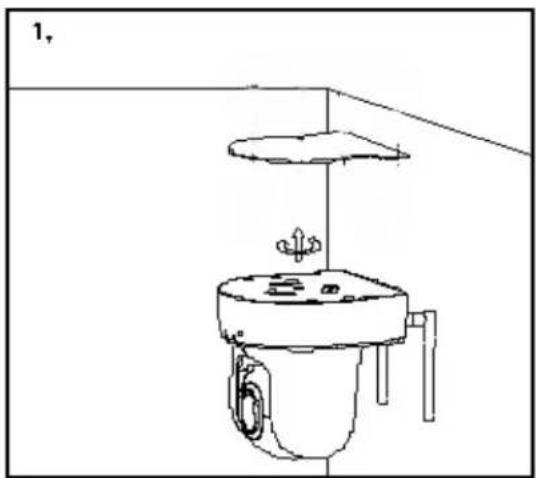
- Slide the metal plate onto the base of the Camera, making sure that the three screws on the plate align with the three holes on the base of the Camera.
- Secure the metal plate to the base of the Camera by twisting the camera to lock it.
- The Camera can now be mounted to the ceiling or a wall. See the diagram below for more information.
natural_image
Line drawing of a toilet with a lid and seat, no text or symbols present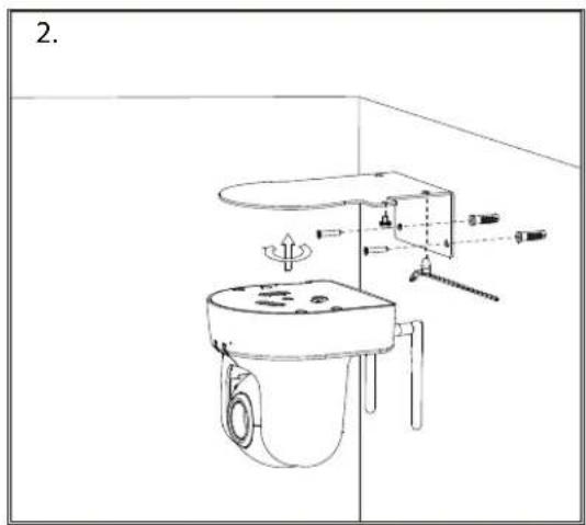
• Install the Camera to the ceiling using the 4 ceiling screws (①);
or
• Install the Camera using the two wall screws ( ②).
Connect Ethernet Cable
To connect the camera to your network, connect a Category 5 or better Ethernet cable to the network cable connector located on the camera's left side panel, and then attach it to the network. The Ethernet port will automatically detect and adjust to the speed (10 or 100 Mbps) and polarity (MDI-II or MDI-X) of the connection.

natural_image
White medical device with attached ports and a connector (no visible text or symbols)Connect Power and Power On Camera
To provide power to the camera, connect the AC power adapter to the DC power input connector, also located on the camera's left side panel, and then plug it to the electrical outlet. As with any electrical device, make sure the power source and camera are located in an area where it is not going to get wet or present an electrical hazard.

natural_image
White portable toilet with attached power outlet and connector (no visible text or symbols)
CAUTION: The Camera must be used with the power adapter included with the device.
Reset Camera
A manual reset can be conducted by following the procedure below. The reset button is located on the rear panel of the camera. To reset the system settings to factory defaults, please follow these steps:
- Use a paper clip or similar object to hold down the reset button for three seconds. The reset button is located on the rear panel of the device. See the Rear Panel Components picture above to locate the reset button.
- Release the reset button and the Power LED will begin to flash, indicating that the Camera is reverting back to factory settings.
Upon restarting the camera loads the factory default configuration settings. The default IP address 192.168.10.30 and subnet mask 255.255.255.0 will be applied unless a DHCP server is actively connected to the network. If using the TV-IP612WN Wireless Camera, the default SSID is "TRENDNet". The administrator's default user name is admin and the password is admin. Use the Setup Wizard shipped with the camera to reconfigure it or access it through the web-based management software.
3
Security
To ensure the highest level of security and prevent unauthorized usage of the Camera, the Administrator account has exclusive access to the camera's configuration settings. The Administrator account can create up to 20 users. A User only has access to the Live View portion of the browser software to view and record video. Access to the Camera is strictly restricted to User's that have been created in the Setup-System-Device Management menu.
4
Application
The TV-IP612P / TV-IP612WN camera can be applied in a wide range of applications, including:
• Monitoring of local and remote places and objects, such as construction sites, hospitals, amusement parks, schools and day-care centers by using a web browser.
• Using the IPView Pro 2 application to capture singles frame images.
- Configuring the Camera to upload images to an FTP Server or sending e-mail messages with single frame images.
The diagram below shows the Camera being used for a number of different applications using the IPView Pro applications and includes basic information that may assist you with installing and configuring the Camera:
Wireless IP Camera Networking Solution

flowchart
graph TD
    A["TV-IP612WN"] --> B["24-Port 10/100Mbps Web Smart PoE switch with 4 Gigabit Ports and 2 Mini-GBIC Slots (TPE-224WS)"]
    A --> C["300Mbps Wireless N Gigabit Router (TEW-639GR)"]
    D["ProView PoE Pan/Tilt/Zoom Internet Camera (TV-IP612P)"] -->|Power + Data (PoE)| E["ProView PoE Pan/Tilt/Zoom Internet Camera (TV-IP612P)"]
    F["ProView PoE Pan/Tilt/Zoom Internet Camera (TV-IP612P)"] -->|Power + Data (PoE)| G["ProView PoE Pan/Tilt/Zoom Internet Camera (TV-IP612P)"]
    H["Internet"] --> I["Green Wi-Fi"]
    J["Internet"] --> K["Green Wi-Fi"]
    L["Internet"] --> M["Green Wi-Fi"]
5
Using the Utility
This chapter describes the software utilities for the IP Camera, including how to set up your Camera with the utility. The SetupWizard has a user-friendly interface that allows you to setup the Camera easily.
SetupWizard
This section describes how to install the SetupWizard and how to use the SetupWizard to setup and install your Camera quickly and easily. To install the SetupWizard on a system running Windows, launch the SetupWizard on the installation CD-ROM and follow the setup instructions.
Installing the SetupWizard
- Click the Setup Wizard button for the Auto-Run menu screen. The InstallShield Wizard will appear:
- Click Next > to continue.

-
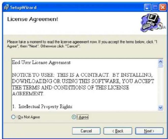
The next window asks you whether you want to accept the License Agreement or not.
-
If you agree with the Licensing Agreement, click the I Agree radio button and the Next > button.
- If you don't agree with the Licensing Agreement, click the I Do Not Agree radio button to exit the install wizard.
-
The following window appears asking you to choose the desired installation location. By default the destination location is C:\Program Files\TRENDnet\SetupWizard.
-
Click the Browse button to change the default installation location.
- Click the Everyone radio button to make the SetupWizard available to all users on your Computer.
- Click the Just me radio button to only make the application available to the user who is running the SetupWizard installation.
-
Click Next > to continue.
-
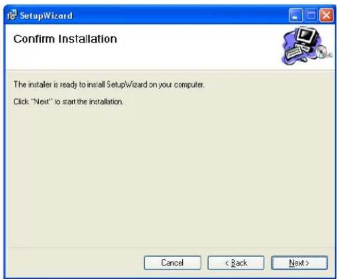
The following window appears informing you that the installation is ready to start:
- Click Next > to start the Installation.

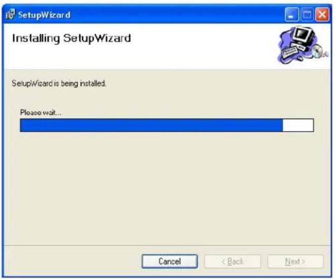
- The software will start to install. The following window appears, showing the progress of the installation:
- When installation is complete the following window appears to confirm that the SetupWizard has installed successfully:
- Click Close to exit the installation

After installing the SetupWizard, the application program for the Camera is automatically installed on your computer.
Launching the SetupWizard
To launch the SetupWizard, click the SetupWizard icon on your desktop or go to Start > Programs > TRENDnet > SetupWizard > SetupWizard to start the application.
SetupWizard- Install Your Camera

■ Connect the camera to your LAN using the provided RJ45 cable.
■ Connect the AC Power Adapter to the back of the camera and to a live power socket.
- Click Next to continue.
SetupWizard- Select Your Camera
The following screen appears showing the cameras that have been found on your network:
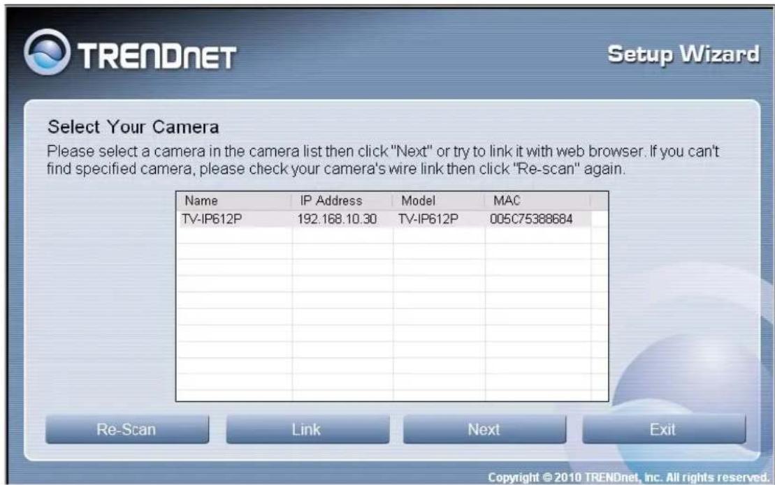
- Click on the camera you want to configure.
- Click Next to continue.
SetupWizard- Authentication
On the following screen type in the ID and Password that you will use to configuring the camera settings:
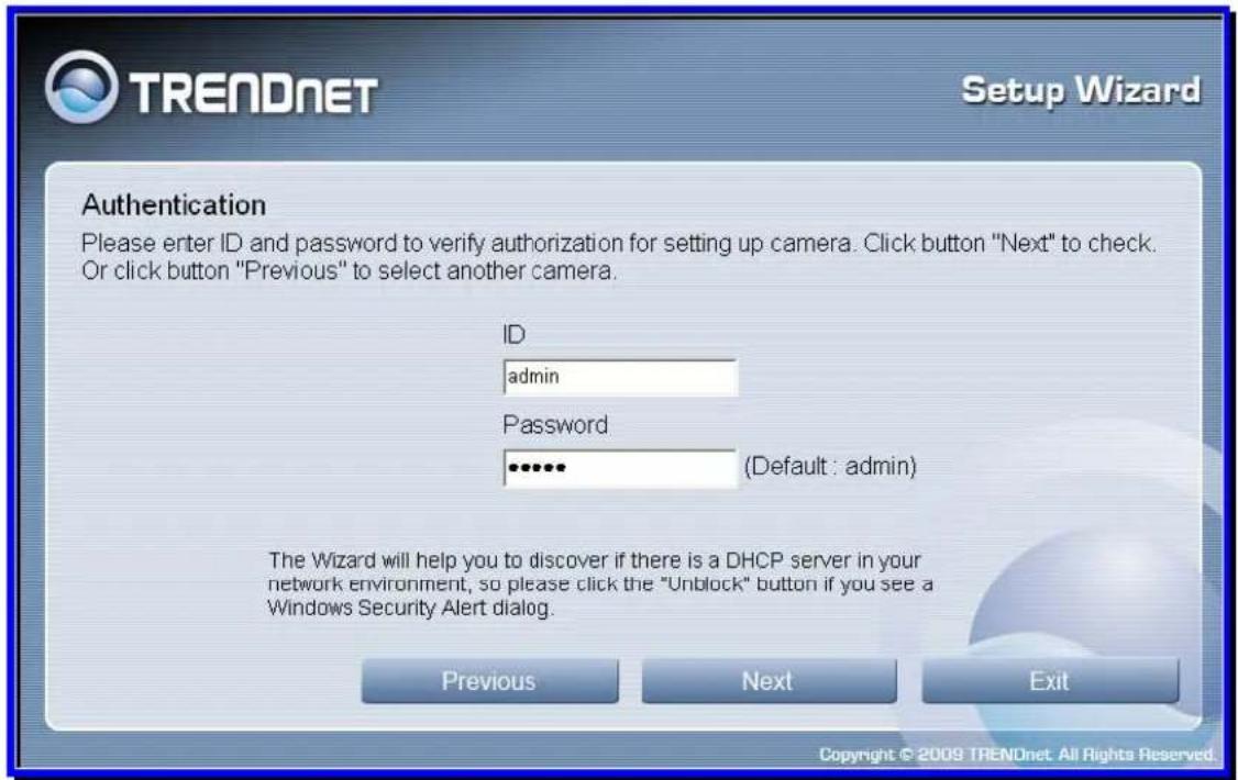
■ Type a User ID in the ID field.
■ Type a password for the User in the Password field.
- Click Next to continue.
SetupWizard- Other Settings
The screen below allows you to set the camera name and the camera's time settings.

■ Type a name to help you identify the camera in the Camera Name field.
- Set the camera date and time from the Camera Time drop-down menus. To use the time settings from your computer, click the Copy Local Time button.
- Click Next when you have finished configuring the other settings.
SetupWizard- Change Password
The following screen allows you to change the default admin password:

Carry out the following if you want to change the admin password:
- Tick the Change Password checkbox
- Type in a New Password in the New Password field and confirm it in the Confirm Password field
- Click the Next button to proceed to the next Setup window
If you don't want to change the admin password, leave the checkbox un-ticked and click Next.
SetupWizard- Select a Connection Option
The following window allows you to specify the connection method used by your camera network.
Click the radio button of the network environment your camera is connected to. The available options are:
- PPPoE
DHCP - Fixed IP
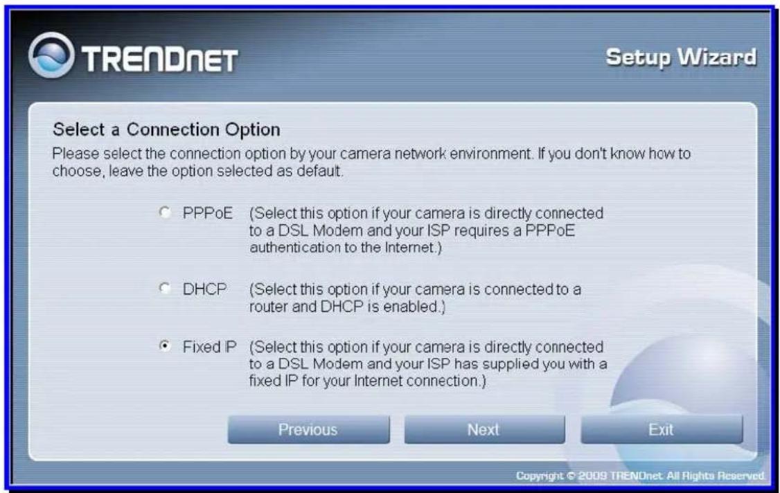
SetupWizard – Select a Connection Option - PPPoE
If your connection method is PPPoE, click the PPPoE radio button and click Next:

The following window appears:

■ Type the User Name used to connect to your PPPoE connection in the User Name field.
- Type the Password of the PPPoE User Name in the Password field and confirm it in the Confirm Password field.
- Click Next to proceed to the next setup window.
SetupWizard- Select a Connection Option- DHCP
If your connection method is DHCP, click the DHCP radio button and click Next:
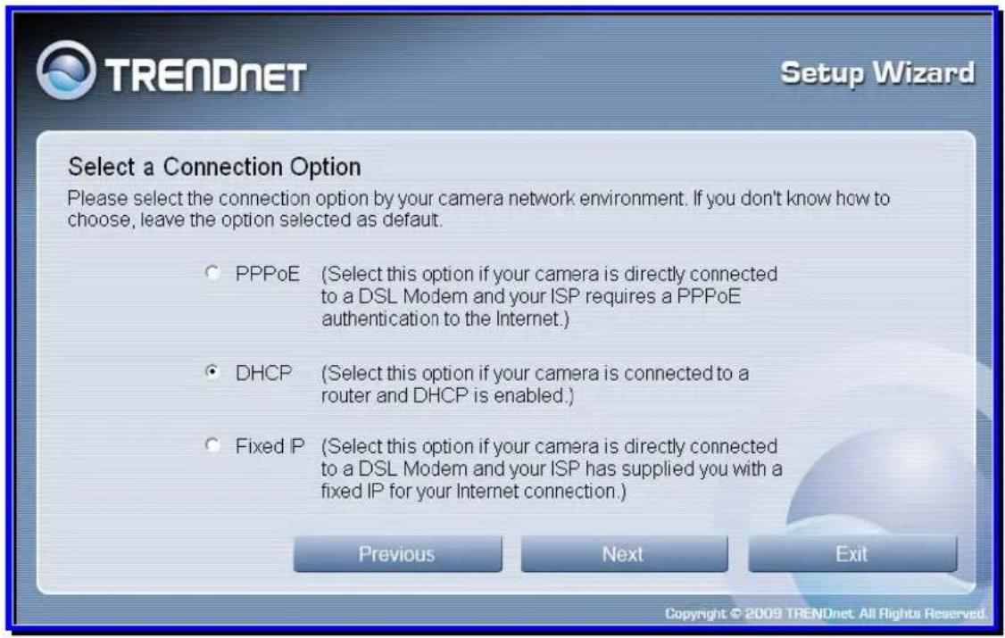
SetupWizard- Select a Connection Option- Fixed IP
If your connection method is Fixed IP, click the Fixed IP radio button:

The following window appears:
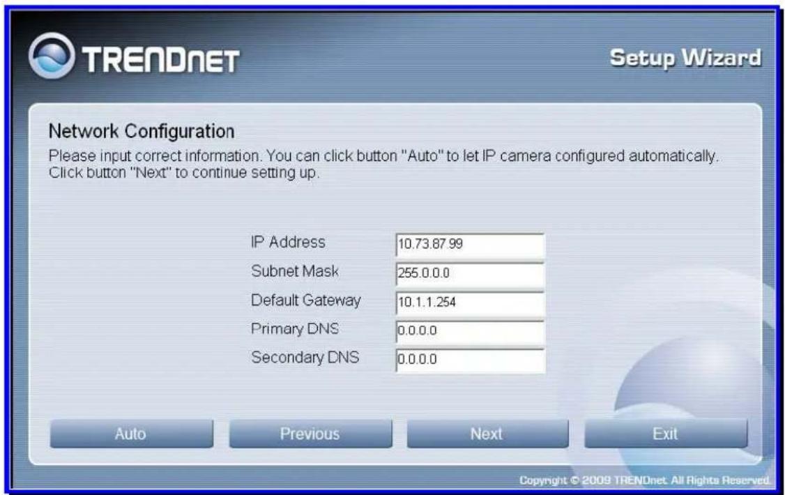
- Type in the IP Address, Subnet Mask, Default Gateway, Primary DNS Server IP address and Secondary DNS Server IP Address in the appropriate fields.
- Click Next to proceed to the next setup window.
SetupWizard- Setup Wireless (For TV-IP612WN only)
After choosing your connection method, the following window appears:

- Choose if you want to connect to your camera using the wireless connection or not by clicking the appropriate radio button.
- Click Next to continue.
SetupWizard- Setup Wireless (For TV-IP612WN only)
If you selected the option to use a wireless connection to connect to your camera the following window appears:
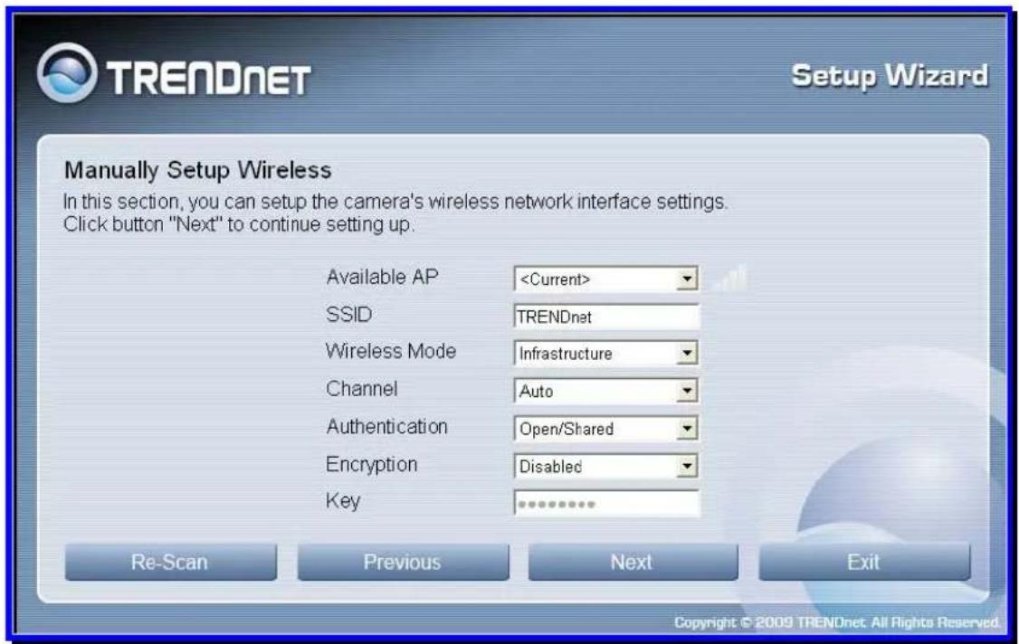
- Choose the Access Point you want to connect the camera to from the Available AP dropdown menu. If the Wireless LAN you want to connect to doesn't appear in the Available AP list, click the Re-Scan button to scan for additional Wireless LAN's.
- Type the SSID of the WLAN you want to connect to in the SSID field.
- Choose the Wireless Mode of your WLAN from the Wireless Mode drop-down menu.
- Choose the Channel of your WLAN from the Channel drop-down menu.
- Choose the Authentication method of your WLAN from the Authentication drop-down menu.
- Choose the Encryption method of your WLAN from the Encryption drop-down menu.
- Type the Encryption Key used by your Wireless LAN in the Key field.
- When you have finished configuring the wireless settings, click Next to continue to the next setup window.
SetupWizard- Setting Up The Camera
The following window appears, summarizing the network settings of your camera:

- When you have finished setting up the Camera click the Next button. To make any changes to your Camera settings, click the Previous button.
SetupWizard- Camera Restart
The following window appears, indicating that the camera is restarting:

SetupWizard- Complete
After the camera has restarted, the following window will appear:

- Click the hyper-link to connect to the camera web interface.
- If you want to setup an additional camera, click the Setup Another Camera button.
- When you have finished, click the Exit button to close the Setup Wizard.
6
Using the Camera Web Manager
The camera is easy to use and manage. Use a normal web browser to access the camera's live video display, as well as the configuration software. It is recommended to check and make sure the computer can access and use the camera before placing it in the location where it will be used, especially if it is mounted to a ceiling or other area that is difficult to physically access.
For the initial setup, use the Setup Wizard program located on the TV-IP612P/WN CD-ROM included with the camera. Use the IPCam Wizard to assign an IP address and other network settings. Once the camera has an IP address, follow the instructions below to access the camera's web management interface used to manage the camera and its video display.
Accessing the Camera Video Display
If the camera is used on a network with an active DHCP server, the camera will detect it and obtain an IP address. If you are using the camera on a network with a DHCP server it is necessary to first determine what the IP address of camera is. To do this, follow the instructions in the Quick Installation Guide to launch the Setup Wizard to link to the camera.

NOTE: If your network uses DHCP or has an active DHCP server running, use the Setup Wizard utility on the installation CD-ROM shipped with the camera to first access the camera. Once it is accessed, you can change the IP address or continue to use the DHCP assigned address as preferred. See the Quick Installation Guide for instructions on using the Setup Wizard utility.
If your network does not use a DHCP server, the camera will use a default IP address of 192.168.10.30. Use this address to access the web-based management software. Use a web browser and type in http:// followed by the default IP address, 192.168.10.30 in the address bar of the browser and press the Enter key. The URL in the address bar should read: http://192.168.10.30
If the login dialog does not appear, check the proxy server settings on your browser.

NOTE: The wrong proxy server settings on your browser can prevent connection to the web manager. If you are having trouble connecting to the web interface of the VLAN Switch, configure the proxy settings to bypass the proxy server or disable use of proxy servers and try to connect again.
To check proxy setting for Windows Internet Explorer:
- In Windows, click on the Start button, go to Settings and choose Control Panel.
- In the Control Panel window, double-click on the Internet Options icon. (Alternatively you can access this Internet Options menu using the Tools pull-down menu in Internet Explorer.)
- Click the Connections tab and click on the LAN Settings button.
- Verify that the "Use proxy server" option is NOT checked. If it is checked, click in the checked box to deselect the option and click OK.
Login
To access the web manager directly from a computer or on a network without a DHCP server running, use the default IP address of the camera in the browser address entry to access the web manager. Type http://192.168.10.30 in the address bar and press Enter. The login dialog appears when accessing the camera.
Type the default user name "admin", default password "admin" and click on the OK button to access the camera's management interface.

Setup - Web Configuration Utility
After successfully logging in, the camera Live View screen will appear. Select Setup to enter into the configuration menu screen.
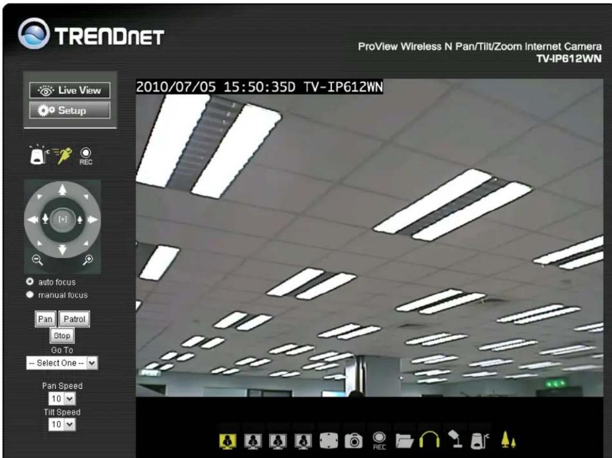
Live View Screen of the camera
Wizard
The first menu to appear after clicking on Setup is the automatic setup wizard. You can use this wizard to configure settings for your camera's Name, LAN and Internet, DDNS and Time/Date. Click on Next to start the wizard otherwise select another menu choice from the left hand menu buttons.

System menu in Administration directory
The different menus that are available are presented and described in the following pages.
Step 1 Setup LAN Settings
Select the DHCP Connection option if your wired or wireless connection will use a dynamically assigned IP address
Select the Static IP Address option and then manual enter in the network settings your camera will use.

Click Next to continue to step 2
Step 2 Setup Internet Settings
To connect a camera directly to the internet using a PPPOE connection enter the username and password here. Your ISP should supply you with the credentials you need. You do not need to configure this setting if the camera is connected behind either a router or gateway.

Click Next to continue to step 3
Step 3 Setup DDNS Settings
To synchronize the public IP address of the Modem, when it has been modified, use the DDNS service settings. You must supply the Username and Password when utilizing the DDNS service.
Server Address: Select your service providers Dynamic DNS web address..
Host name: Enter the Domain name you were given from the DDNS service provider
User name: Enter the account user name your DDNS service provider has given you.
Password: Enter the password associated with the DDNS account user name.
Verify Password: Repeat the password as entered above to verify it.

Timeout: - This setting is the notification period in hours when the camera sends a current global IP address update to the DDNS server configured above. The default is 576 hours. You can setup how often the camera notifies the DDNS server of its current global IP address. By default this is 576 hours.
Click Next to continue to step 4
Step 4 Camera Name Settings
You can assign the camera a name here. Please enter the name and then click next to continue to step 5.

Step 5 Setup Time Zone
Use this step to configure the Time and Date, the Time Zone and the Daylight savings configuration of the camera.
Time Zone: Select the Time Zone for your camera in the drop-down list.
Enable Daylight Saving: Select this to enable Daylight Savings for the Time Zone you have chosen above. This will automatically set daylight savings time depending on the date and time for each time zone.
Keep current date and time: Select this choice to prevent any time and date changes from the current setting.
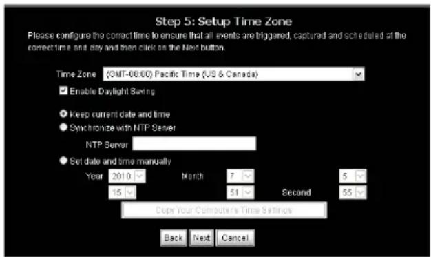
Synchronize with NTP Server: Select this choice to enable NTP time slaved to the NTP server identified below.
NTP Server: Enter the NTP server address or hostname
Set date and time manually: Use this setting and the entry boxes below to enter the date and time desired as a manual configuration.
Copy Your Computer's Time Settings: Click this button to automatically set the time and date based on your computer's settings.
Click Next to go to Step 6
Step 6 Setup Complete
Carefully review your settings and then click Apply to finish the wizard.

The camera will reboot to apply the new settings:

System
The system menu item configures the devices users, associated passwords, device name, OSD settings, and LED light control.
Device Management
Admin Password Settings:
Use the fields to change the administrator password used to access the System
Administration settings. Enter, a password in the
New Password field and confirm the password in the Retype Password field.
Add User Account:
Enter the new users name and password twice; then click add to configure the new user for accessing the Live View video stream. A maximum of 20 users can be configured.
User List:
Click on the pull-down menu to view the current users configured for the camera. To delete a user select the user from the pull-down list and click on the delete button.
Device Settings:
Camera Name: Enter the name desired for the camera up to a maximum of 36 characters.

Enable OSD: Check this box to provide On-Screen Display on the Video Stream from the camera of the following items.
Label: Enter the desired text to identify the camera.
Show Time: check this to show the current time and date in the video display from the camera.
LED light: Clicking the off selection turns the LEDs on the camera off even though the camera is in operation.
Calibrate the Device
Clicking this button will reset the camera to the home position and default settings after a serious of camera checks and movements. Use this in case the camera was moved manually by hand or otherwise.
Time and Date
Time Configuration
Time Zone: Select the Time Zone for your camera in the drop-down list.
Enable Daylight Saving: Select this to enable Daylight Savings for the Time Zone you have chosen above. This will automatically set daylight savings time depending on the date and time for each time zone.
Auto Daylight Savings: This setting automatically is enabled when you check Enable Daylight Savings. Otherwise this setting is disabled when Set date and time manually is enabled below.
Set Daylight Savings Manually: Click this radio button and use the Offset, Start Time and End Time entry boxes below to manually set Daylight Savings for the specific range of date and time.
Offset: The time adjustment in hours forward or back (+/-).
Start Time: When the time Offset will be effected. (Daylight Savings Time).
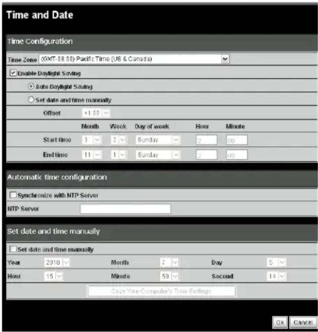
End Time: When the time Offset is no longer in effect (Standard Time).
Automatic Time Configuration
Synchronize with NTP Server: Select this choice to enable NTP time slaved to the NTP server identified below.
NTP Server: Enter the NTP server address or hostname
Set date and time manually
Use these settings to manually enter the time and date for the camera.
Copy Your Computer's Time Settings: Press this button to automatically copy the current computers time and date settings to the camera configuration.
Click Ok to continue to save your settings.
Network
Use the menu selections in this section to configure the network settings for both wired and wireless LAN setups (TV-IP612WN only) of the camera.
Network Setup
DHCP Connection: Select this option to automatically configure the Camera IP settings from a DHCP server.
Static IP Address: Select this option to manual configure the IP settings in the below 5 fields for your camera.
IP Address: Enter an IP address which you will use to access your camera and the web configuration page.
Subnet Mask: Enter the subnet mask to use for the LAN the camera is connected to.
Default Gateway: Enter the default gateway IP address configured for the LAN the camera is connected to.

Primary DNS: Enter the primary DNS address accessible from your LAN.
Secondary DNS: Enter a secondary DNS address.
Enable UPnP: Checking this box enables Universal Plug and Play which will allow windows to create an icon that represents the camera in the "My Network Places"
Enable UPnP Port Forwarding: Checking this box enables the settings below to assign both HTTP and RTSP ports to the camera. The default ports are 80 and 554 respectively.
External HTTP Port: Assign the HTTP port to be used for the camera. More then one camera on a network requires different HTTP ports for each camera to view them from the internet.
External RTSP Port: Assign the Real Time Streaming Protocol Port to the camera. This port is used by RTSP clients used for example on mobiles.
Enable PPPoE: If your camera is connected directly to a service provider using PPP checking this box sets up a PPP session with your network provider and uses the credentials below: If checked provide the user credentials such as username and password in the boxes below.
Port Settings
HTTP Port: Configure this with the HTTP Port to be used for viewing the camera over the internet.
RTSP Port: Configure this with the Real Time Streaming Protocol port used by an RTSP client to view the camera from for example, a mobile or smart phone.
User Authentication: Checking this box forces the user to supply their credentials upon every camera access.
Direct Video Stream Authentication
Enable: Once you enable this feature, you can view your camera from a direct link http://camera_IPaddress/tvaview.htm for Internet Explorer users and http://camera_IPaddress/tvjview for non Internet Explorer users.
Click Ok to continue and save your settings.
Wireless Setup
Enable Wireless: Check this box to enable the wireless network connection mode of the camera
Site Survey: Click the pull-down menu to see the list of wireless networks available.
SSID: The SSID (Service Set Identifier) is the name assigned to the wireless network. Type the SSID of the Wireless LAN you want to connect to in the SSID field or use the drop-down menu to choose the SSID you want to connect the Camera to.
To refresh the list of available Wireless LAN's, click the Site Survey button.

Wireless Mode: Click on the drop-down menu to select either Infrastructure or adhoc wireless mode. Infrastructure allows direct connection to a wireless router or access point. Adhoc is for connecting with another wireless client that is in adhoc mode.
Channel: Use the drop-down menu to choose the channel used for communicating with your Wireless LAN. A “channel” is a range of frequencies used to communicate between the Camera and an Access Point in Infrastructure mode, or the Camera and PC/Notebook in Ad-Hoc mode.
Authentication Encryption: Click on the drop-down menu to select either disable or enable. Enable is automatically sets the authentication.
Key: Enter the exact security key (pass phrase) required for the authentication type.
Selecting a SSID from the Site Survey
When you click on the Scan button in the Wireless menu a list of networks is available in the pull-down list immediately below. Selecting one of these items automatically populates the Wireless Mode, Channel, Authentication and Encryption fields.
Once you select the SSID you must enter the security key if authentication is selected.
Dynamic Domain Name Service (DDNS)
DDNS is a method of keeping a domain name linked to a changing (dynamic) IP address. With most Cable and DSL connections, you are assigned a dynamic IP address and that address is used only for the duration of that specific connection. With the camera, you can setup your DDNS service and the camera will automatically update your DDNS server every time it receives a different IP address. Depending on the service, this update may take a few hours
Enable DDNS: Check this box enables the DDNS function of the camera.
Server Address: Use this box to enter in the DDNS server address or you can click on the drop-box to the right to select a server.
Host Name: Enter your assigned DDNS host name.

User Name: Enter your assigned user name.
Password/ Verify Password: Enter your assigned DDNS password twice for verification.
Timeout: This timeout is the number of hours to wait before the camera is disconnected from the assigned DDNS server.
Status: The status of the DDNS function; whether it is enabled or disabled.
Video Audio
Video and Audio
Video Profile 1-4
Encode Type: Select one of H264, JPEG, or MPEG4 encoding from the drop-down menu. Profile 4 is always set to MPEG4.
Resolution: Select the size of the desired screen viewing resolution.
FPS: Select the FPS (Frames per Second). 30 is the maximum (best quality).
bps: To control the amount of bandwidth that the camera uses select the BPS (Bits per Second). to fix the bandwidth rate. A higher bps provides a better image quality but requires more network band

JPEG quality: If the encoding type selected above is JPEG, then in this menu the quality of the JPEG video can be selected.
RTSP URL: Use this setting to configure a suffix that is added to your cameras RTSP address. For example for a camera with IP set to 192.168.10.30 and RTSP set to 3gpp the entire URL to access this video profile from the camera is: rtsp://192.168.10.30/3gpp
Notes
The following Video Profiles are used for special purposes:
Video Profile 3 for viewing the camera in non-IE browsers. This profile is always configured as MJPEG.
Video Profile 4 is for viewing the camera over mobile devices. This profile is always set to use MPEG-4 encoding.
To obtain a better quality of video the frame size, frame rate and bit rates must be increased however this results in hight bandwidth utilization. For a mobile phone it is suggested to use 5 fps and a bit rate of 20 kbps to obtain and excellent balance of picture quality versus bandwidth utilization.
Audio Setup
Enable Speaker: Check this box to enable the local external speaker on the camera. Using the microphone on your computer allows you to speak to anyone near the camera.
| Audio Setup | |
| Enable Speaker | |
| Volume | 50 |
| Enable Microphone | |
| Volume | 50 |
Volume: Adjusts the volume of the external speaker turned on above.
Enable Microphone: Check this to enable the camera's built-in microphone so that the you can receive audio along with the video from the camera.
Volume: Adjusts the volume of the audio coming from the microphone of the camera enabled above.
After making any changes, click the Save Settings button to save your changes, or click the Don't Save Settings button to discard your changes.
Click the OK button to save and activate your settings.
Image Setup
Brightness: Adjusts the level of the video brightness.
Saturation: Adjusts the saturation value. Increasing the value will increase the boldness of the colors.
Hue: Adjusts the video level of hue which will spectrally shift the colors up or down.
Contrast: Adjusts the level of contrast for the image. A higher value increases the definition of between dark and bright objects.
Sharpness: Adjusts the level of the image sharpness. Lowering the value will soften the image.
Frequency: Select either 50Hz or 60Hz to match the frequency of the monitor scan rate.
Flip: Check this to rotate the video 180 degrees on the vertical axis.
Mirror Check this to rotate the video 180 degrees on the horizontal axis. This is normal used when the camera is mounted upside down on a ceiling.
B/W: Check this to transmit the video in Black and White format.
Advance Image Settings
Auto Gain Control: When the level of input luminance is too dark, setting the AGC to high will automatically increase the image brightness.
Back Light Compensation: When the background of the input image is too bright, use the BLC function to make the objects in the image clearer.
2D Noise Reduction: When you increase the gain, noise in the image is also amplified. Use the 2D Noise Reduction to reduce the gain of the image noise.
3D Noise Reduction: Use this function to provide both temporal and spatial domain noise reduction. This type of noise reduction is very effective against random and Gaussian noise such as for example video images suffering from RF signal noise.

Preferred Mode:
- Select Aperture-preferred to have the camera image set based on the camera's aperture settings and the shutter speed selected automatically.
- Select Shutter-preferred to have the camera image settings be based on the selected shutter speed and the aperture set automatically.
- Select Manual to have the camera image settings based on manual setup of both aperture and shutter speed settings.
Iris Mode: In Aperture-preferred or Manual mode this field shows manual therefore the Iris Value field must be used to adjust the video image. In Shutter-preferred mode the Iris Mode changes to Auto and the Iris is adjusted automatically.
Iris Value: Use this pull-down menu to select an aperture setting in percent when the Auto Iris setting is set to Manual.
Sens Up: When the luminance level of the input image is too dark, the Sens Up function can compensate for this either automatically. Select Auto for Automatic Sens Up compensation and adjust the Sens Up compensation by using the Sens Up Value pull down menu item below. Select off to turn off this feature. Note the preferred-mode must be in Aperture-preferred to adjust Sens-up.
Sens Up Value: If Sens Up is set to Auto use this setting to adjust the value of the Sens Up compensation.
Shutter Mode (Shutter-preferred)
- Select Auto to have the camera shutter-speed be automatically set.
- Select Manual to adjust the shutter-speed of the camera using the Shutter Value settings in the below pull-down menu
- Select Anti-Flicker to remove the flicker caused by indoor lighting of the image.
Shutter Value: Select the desired shutter speed (in seconds) of the camera when the Shutter Mode setting is set to Manual.
White Balance: Adjust the level of White Balance so that white objects in the image appear with the correct white color.
- Select Manual to use the Red and Blue Offset adjustment settings to the right.
- Select Indoor to automatically adjust the White Balance for indoor imaging.
- Select Outdoor to automatically adjust the White Balance for outdoor imaging.
RedOffset: Adjust the Red Level percentage of the image when White Balance is set to Manual.
BlueOffset: Adjust the Blue Level percentage of the image when White Balance is set to Manual.
Deinterlace: Click this box to change the video format from interlaced to progressive.
Wide Dynamic Range: Click this box to adjust the camera settings automatically to increase the visibility and clarity of the brightest and darkest parts of the image.
Reset to Default: Click this button to reset to the factory default video image settings
ICR
The Infrared Cut Removeable (ICR) controls the operation of the ICR filter for changing light conditions such as from Day to Night. This section provides options to control the operation of the ICR filter.
Automatic: In automatic mode the camera will automatically enable or disable the ICR filter depending on the light conditions.

Day mode: If the camera is used only in a bright and well lit area, please select this option.
Night mode: If the camera is used only in a low-light and dimly lit area then select this option to increase the camera sensitivity by operating it in Black and White mode.
Scheduled Mode: This item allows you to manually program the time when the camera is in day mode using the From (24hr) and to (24hr) fields. Select scheduled mode and then enter the time you want to start day mode in the From (24hr) field and the time you want to end the day mode (start night mode) in the to (field).
Action
Use this section to set up various actions to take based on input triggers preprogrammed.
Recording
Enable Recording: To enable the recording function check this box.
SD Card: Selecting this enables recording to a Micro SD memory card inserted in the camera.
Samba Network Drive: Select this item to record to a Samba network drive.
Samba Auth: From the drop down menu select the authentication type.
User Name: Input the Samba user name assigned.
Password/Confirm: Input the Samba password assigned twice to confirm it.

Server: Use this field to input the Samba drive URL or IP address.
Shared Folder: Input the name of the shared folder to use. (eg. TV-IP612P)
Test: Clicking Test verified that your settings are correct.
Samba Status: Check this item to see if the Samba drive is enabled and use to Get Status button to check it.
Recording Options
Resolution: Select the profile from the drop-down menu. Refer to the Audio and Video section for more information on profiles.
Record File Size: Select from 1 to 10 minutes in the pull-down menu.
Record until: Enter the minimum available hard drive space that must be left free and available for use when recording.
When Storage is Full: Use the Stop Recording setting to stop the recording when there is no longer any hard drive space. Otherwise use the Overwrite older recordings setting to record over old data when there is no longer any hard drive space.
Scheduling
Event Based: Click this setting to use event based triggering
Motion detection triggered recording: Select this option to start recording upon motion being detected.
Digital input 1 triggered recordings: Select this option to start recording upon Digital Input 1 sending an active signal.
Prerecord Seconds: This settings causes the camera to buffer a certain amount of video set in this field to save when motion is detected. The maximum amount of pre-detection video recorded is 15 seconds.

Postrecord Seconds: Once event-base triggered recording begins and the event (for example motion detection) has ceased it will continue recording for the amount of time set here. A maximum post-event recording time of 15 seconds is settable.
Continuous: Selecting this option causes the camera to record video continuously. Only for use with Samba.
Scheduled: Selecting this option allows you to manually schedule when the recordings with begin and end each day.
Snapshot
Enable Snapshot: This option allows you to send an snapshot or still image from the camera attached to an E-mail or via an FTP server.
Trigger Event: These 2 options determine when to transfer an image via email or ftp. The image is sent either based on a Motion Detection trigger or a D/I Signal 1 going active option.
Continuous (FTP Only): This option causes snapshots to be sent non-stop. See the FTP Time Interval Setting.
Scheduled (FTP Only): This option allows you to schedule the specific period (start/end) in the snapshots to an FTP server. See the FTP Time Int

Email Settings
E-mail Address: Check this option to attach the image to an email sent to the user (email address) specified below.
User Name: The ISP username used. For example it could be t_jones or t_jones@homeisp.com.
Password: The account password for the username configured above.
SMTP Mail Server: The email server's hostname such as for example: smtp@t_jones.com.

Sender E-mail Address: The address used for the sent field of the e-mail with the image attached. This will receive deliver failure messages should there be problems with the email address specified previously for the destination. An example would be: t_jones@homeisp.com.
Recipient E-mail Address: The email address that will receive the images captured by the camera and attached to an email
Port: The port used by your SMTP service. Default port is 25.
FTP Settings
FTP Server: Check this option to send the image captured to a FTP server.
User Name: The account user name assigned and used for accessing the FTP server.
Password: The password used for the account username configured above.
Host Name: The FTP server's hostname or IP address. For example: ftp.trendnet.com.
Path: The FTP server file system path to the directory where the image is uploaded to. For example: \TV-IP612P
Filename Prefix: Use this field to configure a prefix added to the front of the filename used for each image.
Port: The FTP server port address normally set to the default of 21.
Interval: The interval time between images (snapshots) taken for the continuous or scheduled mode.
Passive Mode: Check this option if the FTP server configured is setup for passive mode clients. An FTP server setup in passive mode uses random ports for the file transfer.
Preset Position
Presets allow you to program a home camera view and programmable positions and save them for future viewing and recording.
Camera Control
Set as Home: Clicking this button sets the Home position to the current view.
Default Home: Clicking this button sets the home position of the camera view to the default factory programmed position.
Pan Speed: Use this drop-down configuration to set the camera panning speed from 1 to 10 where 10 is the fastest panning speed.
Tilt Speed: Use this drop-down configuration to set the camera tilt speed from 1 to 10 where 10 is the fastest tilt speed.
Current Postion: Type a name to use for the current camera view you would like to save as a preset position. Then click the Add button to save it.

Patrol Selection: This box shows the available Preset Locations saved which can be moved to the Selected Locations box below by highlighting them and clicking on the Select button.
Selected Locations: The preset locations in this box: determine the locations the camera will view when the Patrol button is pressed in the Live View window.
Pan/Patrol Speed: Set the speed from 1 to 5 with 5 being the fastest. This controls the speed of the camera movements when either the Pan or Patrol button is pressed in the Live View page.
Dwelling Time: The setting here determines how long the camera spends at the preset position. Enter from 1 to XXXX seconds.
Click the Save button to save and activate your settings.
Digital Output
The camera's Digital I/O terminal block is the physical connection or interface for connecting external devices such as InfraRed Sensors, Alarm Relays, and Srents to the TV-IP612P/WN camera.
External Digital Input/Output Connectors
Digital I/O Terminal Block Description
The TV-IP612P/WN camera is equipped with a Input/Output terminal block that provides a single digital input and a relay to control external devices. Using Pins 1 and 2 allows you to connect a devices such as an external sensor (e.g. IR Sensor or Alarm Relays) so that the camera can monitor the voltage state where the initial state is set to "LOW" or deactivated. Pin 3 and 4 are connected to the camera's output relay so that an external device can be controlled with "HIGH" activate or "LOW" deactivate signals (e.g. an external circuit to operate a Siren).
Using the I/O terminal block allows you to connect multiple external alarm devices that can then be used to trigger image recording or snapshots that can be stored or emailed to a remote location. Below is the diagram of the terminal block with the connector pin descriptions.
Input Output (I/O) Connector

Trigger
Enable D/O Signal: Checking this box turns on the Digital Output to trigger external equipment such as alarm lights or sirens.
Trigger Event
Motion Detection: Checking the motion detection box causes the D/O pins to activate connected alarm devices upon motion being detected.
D/I Signal 1
Check this box to enable input on the D/I pins connected to a traditional alarm detection device.

Click the OK button to save and activate your settings.
Motion Detection
Live Video
Enable Video Motion: The camera can be setup to record whenever motion is detected in the camera's field of view and programmable predefined areas. Check this box to the motion detection function.
Sensitivity: This field allows you to to specify how much movement will trigger motion detection in the trigger area. A higher sensitivity value means less movement is required. The trigger area is defined using the Drawing Mode check boxes below.
Drawing Mode:
Draw motion area:
Select to draw a motion area. Then use the mouse holding the left button down to drag a red squared area in the Live Video screen. The red grid that appears after using the mouse is the area selected to detect motion. In the Live View screen, when motion is detected in the red grid area then the motion detection symbol will blink according to the movements. See below note.
Erase motion area : Use this check box to be able to erase the Motion Detection area by dragging the mouse over it while holding the left button down.

Clear: Click the Clear button to remove all drawing areas.
Motion Detection Indicators

Motion Detected

No Motion
Detected
Note: The motion notification will continue to blink as long as motion is detected. If no additional motion is detected, it will return to its original state after eight seconds.
Click the OK button to save and activate your settings.
Tools
Backup and Restore
Save to Local Hard Drive: To save the configuration to a file clock on the Save Configuration button.
Load From Local Hard Drive: If you need to load a saved configuration file into the camera click the Browse button and find and select the configuration file to be loaded. Then click the Load Configuration button to load the file which will apply the saved settings once loaded.

Restore to Factory Defaults: To set the camera to the factory default settings click the Restore Factory Defaults button.
Reboot Device: To restart the camera, click the Reboot Device button.
Firmware Upgrade
Please check the TRENDnet Support webpage to check if any new firmware version is available for your camera. The current firmware utilized by the camera is listed in the Firmware Upgrade page in the Firmware Information section.
Firmware upgrade
Step 1. Once you have a new firmware version available for upload click on the Browse button to select the file from your files system.
Step 2. With the firmware file selected click on the Upload button which will begin the firmware upgrade.

Note: Do not turn off power to the camera while the firmware upgrade is in process.
Device Info
Device Info
Detailed information about your camera' system and network settings can be found on this page
| Device Info | |
| Information | |
| Camera Name | TV:JP612VW |
| Time & Date | Mon Jul 5 16:16:37 2010 |
| Firmware Version | 1.00, 4424 |
| MAC Address | 00:01:06:32:B7:54 |
| IP Address | 192.168.10.30 |
| IP Subnet Mask | 255.255.255.0 |
| Default Gateway | 192.168.10.30 |
| Primary DNS | |
| Secondary DNS | |
| PPPoE | Disable |
| DDNS | Disable |
Log
Logs recorded by the camera can be viewed on this page. Click the Download button at the bottom of the page to save the log file to a text file on your hard drive.
| Log |
| current log |
| 2010-01-04 05:05:41 System is booted up. |
| 2010-01-04 05:06:17 admin is starting to watch video streaming by http |
| 2010-01-04 05:08:32 admin is starting to watch video streaming by http |
| 2010-01-04 05:08:35 admin is starting to watch video streaming by http |
| 2010-01-04 13:32:59 System is booted up. |
| 2010-01-04 13:38:50 System is booted up. |
| 2010-01-06 12:14:19 System is booted up. |
| 2010-07-07 08:16:30 System is booted up. |
| 2010-07-07 08:11:05 admin is starting to watch video streaming by http |
| 2010-07-07 08:11:29 admin is starting to watch video streaming by http |
| 2010-07-07 08:11:45 admin is starting to watch video streaming by http |
| 2010-07-07 08:12:30 admin is starting to watch video streaming by http |
Viewing Video
The TV-IP612P /TV-IP612WN camera allows you to view video images using in your web browser. Click the Live View button on the screen to access the video images.
Note: If you Left Click anywhere in the image this will cause the camera to position the center of the image over the point you clicked.

Camera Name and Date/Time: The camera name and the correct current date/time will be displayed when the related information has been entered in the Configuration section of the Web Configuration Utility.
Controlling the Camera
You can control the Camera's viewing angle using the control buttons on the left-hand side of the viewing window. You can control video modes, audio modes, recording settings and digital output using the control panel underneath the image (described on the next page).
Outer Ring: Click on the arrows on the outer ring to move the camara. Click the right arrow to move the camera to the right, the up arrow to move the camera up, etc.
Home: Click the Home icon to move the camera to its home position.
Inner Ring (Optical Zoom): Click the left button to zoom in and click the right button to zoom out
Auto Focus: Click to allow the camera to focus automatically (recommended).
Manual Focus: Click to manually focus the camera. Use the - and + buttons to focus in and out.
Pan: Continuously pans the camera one full cycle
Patrol: Enables the Auto Patrol feature. Please refer to page 47 to configure preset locations.
Stop: Stops movement of the camera during pan or patrol
Go To: Select a preset position from the drop-down menu to move the camera to.
Pan Speed: Select the speed at which the camera will pan (1-10, 10 = fastest).
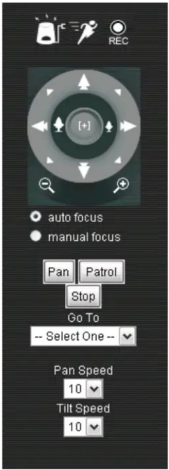
Tilt Speed: Select the speed at which the camera will tilt (1-10, 10 = fastest).
SD Status: Displays the status of your Micro SD memory card. If you do not have a card inserted into the camera, it will display as Invalid.

- Video 1 - Click this button to view the image using Video Profile 1 settings. Go to the Setup section Video/Audio – Video and Audio to change the Profile settings.
- Video 2 - Click this button to view the image using Video Profile 2 settings. Go to the Setup section Video/Audio – Video and Audio to change the Profile settings.
- Video 3 - Click this button to view the image using Video Profile 3 settings. Go to the Setup section Video/Audio – Video and Audio to change the Profile settings.
- Video 4 - Click this button to view the image using Video Profile 4 settings. Go to the Setup section Video/Audio – Video and Audio to change the Profile settings.
- Full Screen – Clicking this button expands the camera view to full screen. Pressing ESC on the keyboard return the view to the standard view.
- Snapshot – To record a still image of the current camera view click this button. The image appears in a new browser where you can save the file from.
- Recording – Clicking this started the video recording function. Clicking again stops the recording.
- Set Storage Folder – Clicking this icon allows you to set the folder on the file system to store video and snapshots.
- Listen – Click this to turn on or off the camera's microphone. The microphone in the camera allows you to hear any audio in the vicinity of the viewing area. The default is on.
- Talk – Clicking this causes the audio from a microphone or other source at the computer to be fed to the speaker output (A/V jack) at the camera. Use this to speak to anyone in vicinity of the camera
- Start Digital Output – Click this on activates the digital output signal
- Digital Zoom/Pan & Tilt – Changes the pointer over the image to a magnifying glass when the icon is highlighted yellow. Clicking the pointer causes the image to be zoomed with the center at the click point. Clicking the icon again to turn of the yellow highlight changes the pointer to a Pan and Tilt function only when the pointer is clicked anywhere on the image.
7
IPView Pro 2.0
This section describes the how to setup a camera using the IPView Pro 2.0 camera monitoring software. To install IPView Pro 2.0 on a system running Windows, launch the IPView Pro 2.0 installation software on the installation CD-ROM and follow the setup instructions. Once the software is installed, the IP Cam Center camera monitoring utility is ready for use. Add up to 32 network cameras to monitor using the software. Additional software, IPCam Player software is also installed. The IPCam Player is used for playing recorded video from cameras that have been configured to save recorded files.
Launching IPView Pro 2.0 for the first time
To launch IPAddress Pro 2.0 double click on the IPAddress Pro 2.0 icon on your desktop or go to Start > Programs > TRENDnet > IPAddress Pro 2.0 > IPAddress Pro 2.0. If this is the first time using the software, the menu that appears is the Add camera menu. To add your IP camera:
- Search for the IP camera on the local area network (click on refresh) or
- Import an existing configuration file

Add a camera for monitoring
The Add camera menu is presented the first time the IPAddress Pro 2.0 software is launched. This menu is used to add cameras to the user interface for monitoring. After the first time running the software, this menu can be accessed at anytime from the Configuration menus. The Configuration menus are described in a later section of this chapter. Notice that the IPAddress Pro 2.0 software has automatically detected eligible cameras running on the network.
To add a camera to the IPCam user interface, follow these instructions:
- Check the list of cameras detected by the software. If the camera you want to add does not appear on the list, click the Refresh button to conduct another search. If it still does not appear, check the IP address of the camera and click on the Input the location of camera menu tab and skip ahead to step 2.1.

- Select the camera to add from the list, enter the administrator's user name (ID) and password, a preview of the live video display will appear. Click the OK, add this camera button, a confirmation message informs when the camera is connected and added to the IPView Pro 2.0 monitoring group. Repeat this procedure for all the cameras being added. Click the Exit button after all the cameras have been added.
If the camera does not appear listed, click the Input the location of camera tab above the list to view a new menu. Enter the IP address or the URL (for example, ipcam.ddns.org) of the camera being added, type the user name and password and click the Preview to verify that a link can be established. The live video of the camera should appear in the Live preview display. If a link cannot be established, run the Setup Wizard software for the camera and verify the correct IP address. Click Exit to return to the main Add camera menu.

- Once the cameras have been added, they are ready to be used in the main IPView Pro 2.0 user interface. Close the Add camera menu (click Exit) to go to the main user interface. See below for a description.
IPView Pro 2.0 User Interface
Below is a general description of the user interface.

| NO. | Item | Description |
| 1 | Live video display area | Display area for single or multiple cameras of live video. Right click on any display area to view a list of quick configure options for that camera including the “Replace camera content ...” option used to change the order of the live video displays for multiple camera views. |
| 2 | Minimize and Exit | Use to minimize IPIview Pro 2.0 interface or exit the program, a confirmation is required to exit. |
| 3 | Pan and Tilt control (cameras using RS-485 Pan/ Tilt device only) | Click directional arrows to move camera in that direction within the limits of the pan and tilt range. The + in the center of the control is used to return to the home or center view as configured for the camera. |
| 4 | Zoom | Click the + or - buttons below the Pan and Tilt Control Warning: If the camera does not focus go to the Live View portion of the Browser and make sure that auto focus is checked (i.e. Not manual focus). ** the pan/tile speed control above Zoom can also control the zoom in/out distance** |
| 5 | Snapshot, recording and audio controls | See below for detailed information. |
| 6 | Live video display controls | See below for detailed information. |
| 7 | Camera configuration menu | See below for detailed information. |
| 8 | Camera status | Use to quickly assess the status of operating cameras. Click on box to select camera display. The status indicators for each camera display recording, motion detection and GP input status. |
| 9 | Camera information | Displays basic information on selected camera. |
Display Controls
The primary display and IPView Pro 2.0 control icons are described in detail below. When there are more than one camera displays viewed, one of the displays can be selected for management or additional changes. Simply left click on any display to select it. Notice the border around the display is bright aqua blue, indicating the “selected” status. For example, to go to a single screen display for any one camera, select the camera and click on the single screen display.
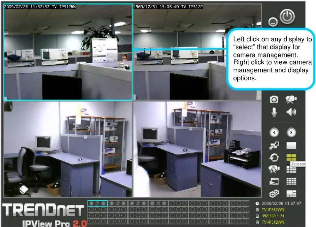
Snapshot, recording and audio controls
The still photo camera icon is used to take a snapshot of the selected live video display. The video camera icon is used to begin video recording of the selected live video display. Snapshot and videos files are stored in a default folder on the administrator's system, or in a folder designated by the administrator.
The audio controls are represented by a microphone icon to activate the internal mic or the auxiliary audio input (if present), and a speaker icon for the audio output (remote speakers, if present).
Notice that when these functions are activated, the color of the icon changes from white to yellow.

flowchart
graph LR
    A["Input Image"] --> B["Video Camera"]
    B --> C["Speaker"]
    C --> D["Audio"]
    D --> E["Output Video Camera"]
Audio and video controls - inactive
Audio and video controls - activated
Live video display controls
Use the video display controls to change the view of the live video display. This is useful for multiple camera application.
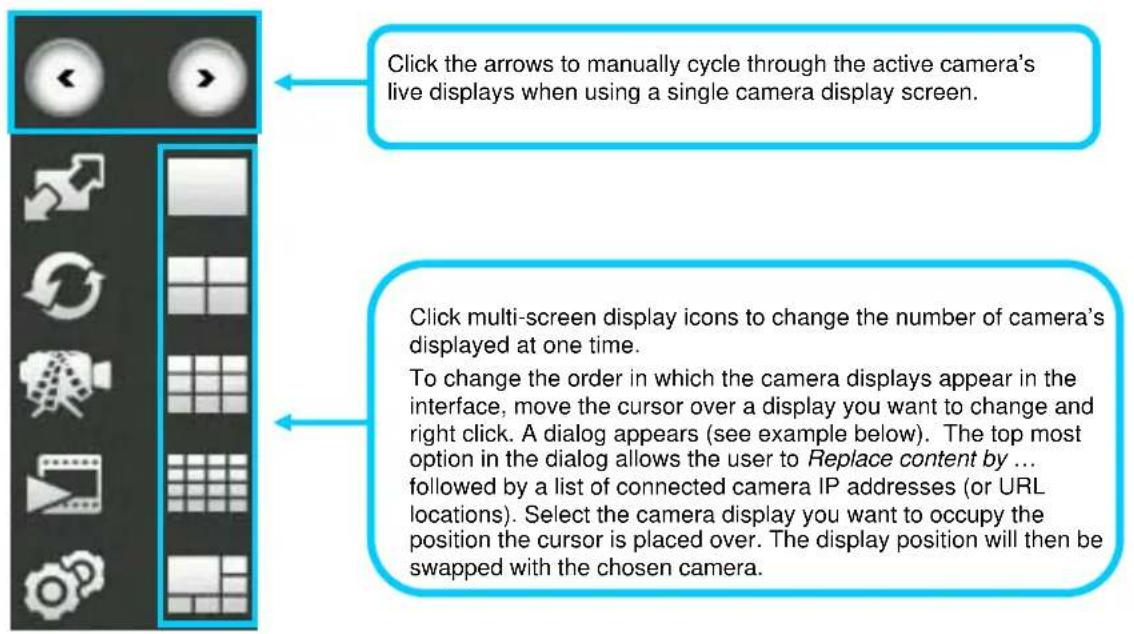

flowchart
graph TD
    A["Switch to full screen view of selected display screen."] --> B["Click to record all active cameras."]
    B --> C["Click to add or configure cameras. See details below."]
    D["Click to automatically cycle through the active camera displays."] --> E["Launch IPCamPlayer to view stored video files."]
Camera configuration with IPView Pro 2.0
Access the camera configuration menus by clicking on the gear icon at the bottom of the right hand panel of the IPView Pro 2.0 user interface. Configuration options include adding and deleting cameras from the display view, configuration of motion detection and digital input with schedules, recording options, email alerts and other network settings.
Adding a Camera – Camera management
The procedure to add a camera after the initial launch of the software is very similar to the procedure used during the first setup. Follow the instructions below to add cameras.
To add a camera:
- Click the Configuration icon to view the Camera Setup menu. The top most tab of the menu is the Camera Management tab. A list of active cameras appears on the left half of the menu. Select the camera to be added from the list. Click the Add Camera by IP Address to find the specified IP address or network URL of the camera you want to add.

- Select the camera to add from the list, enter the administrator's user name (ID:) and password, a preview of the live video display will appear. Click the OK, add this camera button, a confirmation message informs when the camera is connected and added to the IPView Pro 2.0 monitoring group. Repeat this procedure for all the cameras being added. Click the Exit button after all the cameras have been added.

- The camera added now appears in the Camera List. To launch the web manager for the newly added camera or any camera in the active camera list, select it and click the Browse Selected Camera button.
Removing a Camera
To remove the camera from the list of active:
- Select the camera you want to remove.
- Click Delete Selected Camera.
NOTE: Any camera display can be removed from the main IPView Pro 2.0 user interface by right-clicking on the display screen for the camera and selecting the Remove this Camera option.
Launch Web Manager for Selected Camera
To launch the web-based IP Camera manager for any active camera in the list, simply select it and click the Browse Selected Camera button.
Schedule Recording with IPView Pro 2.0
Use the Monitoring Settings menu to create schedules for recording and apply the schedules to any camera. Click the Monitoring Settings tab to view the Schedule Recording menu (the first menu viewed in the Camera Settings menu tab).
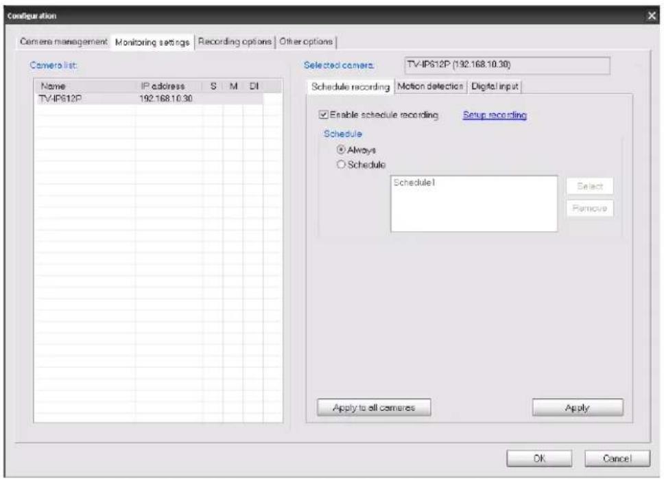
To apply an existing schedule template, click the Enable schedule recording checkbox then click the Select button and choose a schedule from the list of previously created schedule templates by checking its checkbox and click the OK button. If a new schedule is needed it can be created by clicking Select button and then the Edit profiles button in the Select schedule profiles dialog box.
Create Schedule Templates
To make a new schedule template, click the Edit Template button to view the Select schedule profiles dialog box. Use this new dialog box to create new schedules for recording.

Setup Motion Detection and Digital Input with IPView Pro 2.0
The Camera Settings menus include Motion Detection setup and Digital Input control. Each menu has the schedule option to apply a schedule for the action taken or always take the specified action.

For Motion Detection, use the Config motion detection area menu to create the area to which it is applicable. Click the Config motion detection area button in the Motion Detection setup menu to view the menu in a new pop up window. High sensitivity rate leads to
![Setup motion detection of the camera [192.145.10.30] Motion detection Sensitivity 100 0~100% Drawing mode Draw area Erase area Select all Clear Save settings Exit](/content/2026/05/1048447/images/dae0e9c23aa122edcb367c27ed1d5b3e00287db2c7fe81cecdeb42447afde435.jpg)
The sensitivity value is based on a scale. The lower the sensitivity rating the more motion will be required to trigger an event. Using too high a sensitivity rating may trigger false events.
IPView Pro 2.0 Recording Options
The Recording Options configured in the IPView Pro 2.0 help to conserve and manage allowed memory storage (disk space) and for video file management. Recorded files can be limited by time elapsed or by size. Use the select storage folder to choose an alternative destination for stored video files. Storage limits can be set for each camera by time elapsed or hard disk space allowed. A limit can also be placed for the system and all cameras used in IPView Pro 2.0.

pie
| Category | Percentage | | -------------- | ---------- | | Total | 43.6% | | Used | 11.3% | | Available | 53.8% | | Reserved | 500% | | Current camera | 22031 MB | | Total quota | 500 MB | | Free | 21031 MB |IPView Pro 2.0 Miscellaneous Options
The Other Options available for configuration include Proxy server setup, email notification, scan interval and alert type settings.
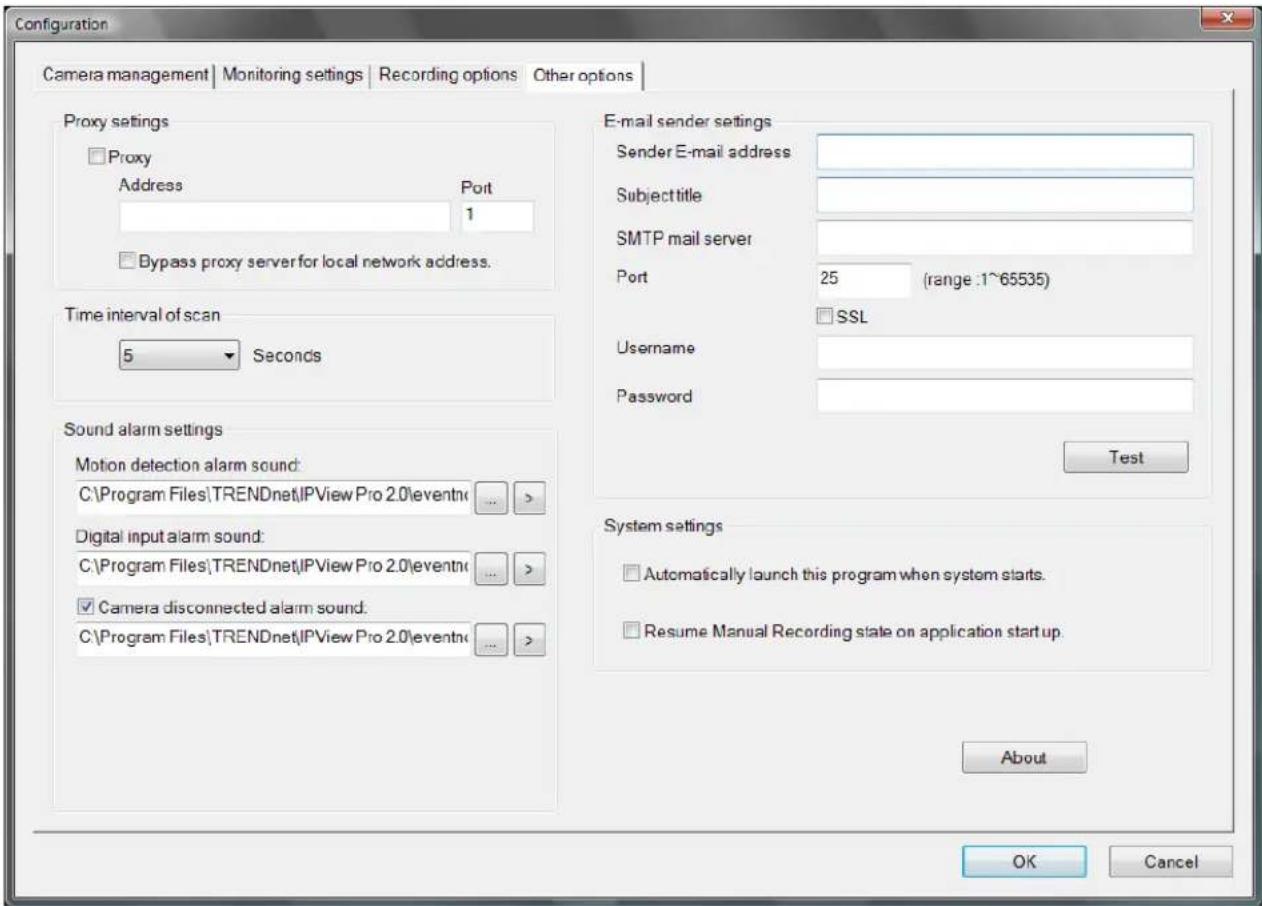
8
Playing Video Files on a Computer
IPCamPlayer software is installed on the monitoring station or administrator's system along with the IPAddress Pro 2.0 monitoring software. Use it to playback and manage recorded video from the cameras added to the IPAddress Pro 2.0 group. In order to use the software however, it is necessary to first install the ffdshow package of codecs used for media files. There is an ffdshow installation file on the CD shipped with the camera. Install ffdshow before using the IPCamPlayer. For information on installation and use of ffdshow, see the ffdshow section at the end of this chapter.

The IPCamPlayer can be launched directly from the IPCamCenter or from the Programs menu. To launch the program from the IPView Pro 2.0 interface, click the movie icon on the control panel of the main IPView Pro 2.0 interface to launch IPCamPlayer.

NOTE: Install the ffdshow package of video codecs from the installation CD before using the IPCamPlayer.
Load Saved Video Files
Each camera has a file created automatically for storing video files. These files are normally located in the My Documents folder in Windows. The file folders are named according to the IP address and camera model. For example, 192.168.10.30_TV-IP612P/W is the name of the file folder for the TV-IP612P/W using the default (non-DHCP) IP address.
IPCamPlayer User Interface

| NO. | Item Description | |
| 1 | File list Video files added to | the list are viewed in the order listed. |
| 2 | View Screen | Video files in the list are played here. The progress bar and starting time of the video clip appears beneath the view screen. |
| 3 | Add/ Delete files from list | Use the Search Files button to add recorded video files. A new menu pops up that is used to find and add files to the list. (See description on next page) |
| 4 | Playback controls | Standard video playback controls for Stop, Play/ Pause, go to next file (>>) or go to previous file (<<) Faster and Slower to control speed of playback. Playback can be slowed to as much as 1/8 normal speed or speeded up to as fast as 8 times the normal speed. The vertical slider control is used for audio volume control. |
To view recorded video files in the IPCamPlayer, it is first necessary to locate and select the files to be viewed and add them to the list. Click the Search Files button in the IPCamPlayer main interface and a new menu appears.
In the new menu, use the Select Camera pull-down menu to choose the video file folder of the camera to be reviewed. Use the Search Time menu to narrow the search to a specific time and date. Finally, the Event selection menu is used to further narrow the scope of the file search for videos triggered by Motion Detection or a Digital Input device. When the search criteria have been defined, click the Search button to place qualified files in the Search list.

Choose the files to be added to the view file list by check marking the individual files or click the Select All button to check mark all files in the Search list, click Add to place the check marked files on the list of files for viewing.
After the files to be viewed have been chosen, click the OK button.
Play Video Files
Now that the recorded video files have been selected and placed on the file list, they can be played and reviewed in the IPCamPlayer. Use the standard playback controls to play video files at normal speed or slowed down, paused, speeded up etc. Use the mouse and left click to grab the playback sliding progress indicator to move back and forth through the video.
ffdshow
The ffdshow software is used for audio and video encoding and decoding, especially for MPEG-4 formats. It is free software used on Windows systems and enables the user to tweak media playback and select specific codecs and formats. For use with the IPCamPlayer, the default settings used for ffdshow installation are all that is needed. Expert users can change audio and video codecs as desired with one of the three ffdshow configuration utilities installed along with the codecs. The configuration utilities can be accessed after installation from the ffdshow folder in the Programs folder (Start > Programs > ffdshow >[configuration utility]).
Install ffdshow
- Insert the CD-ROM into the CD-ROM drive to initiate the auto-run program. The menu screen will appear as below:
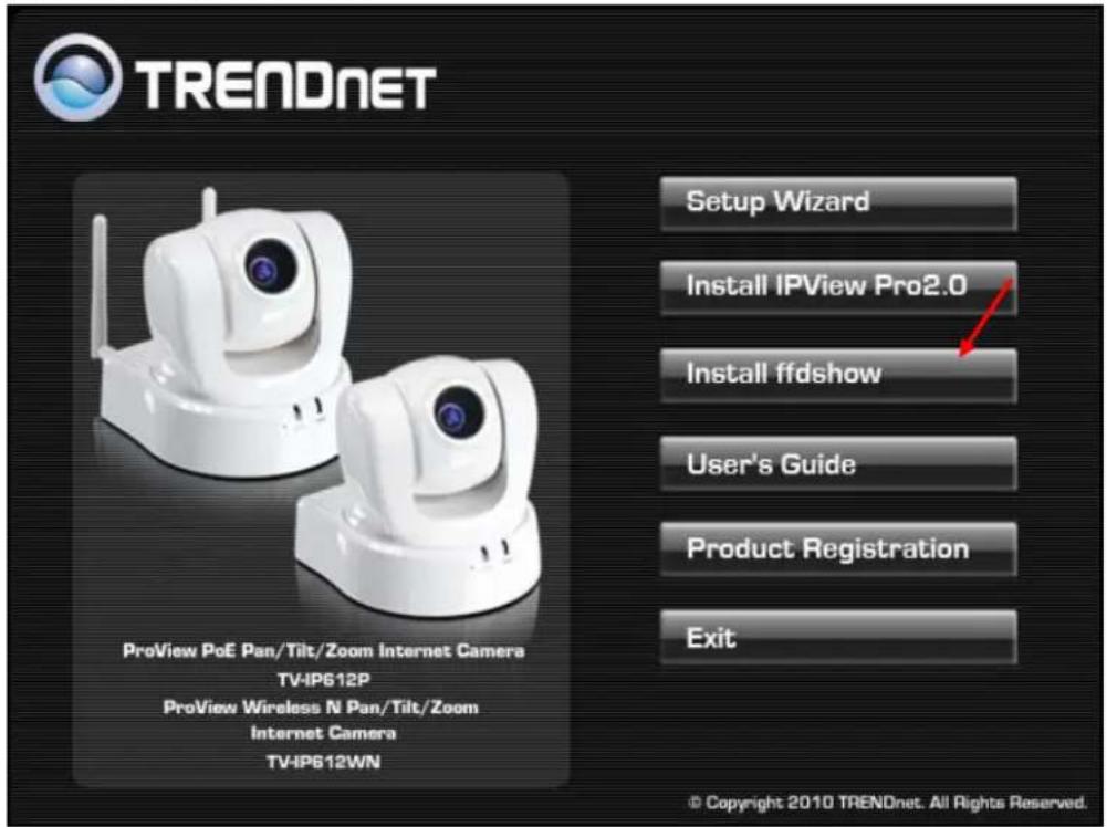
- Click the ffdshow install link, and select the desired language in the pop-up dialog window.

- The InstallShield Wizard will appear, click Next in the welcome screen.
![Ifdshow [rev 2033] [2008-07-05] This will install Ifdshow on your computer. It is recommended that you close all other applications before continuing. Click Next to continue, or Cancel to exit Setup.](/content/2026/05/1048447/images/5ef075db10e3607053326735451ec83914bc09a0559052459e97f398f4d5bda1.jpg)
- Accept the default location (Windows Programs folder) on the system for placement or Browse to choose an alternative, Click Next to continue.
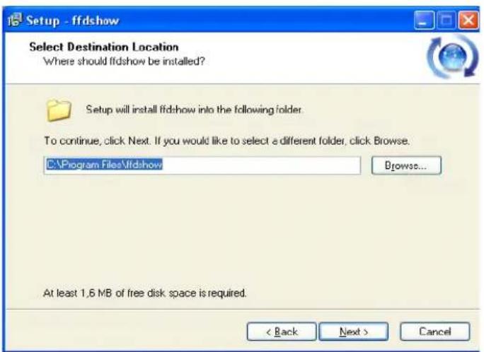
- Click to check the components that will be installed. For IPCamPlayer it is only necessary to use the default components already selected. Click Next to continue.
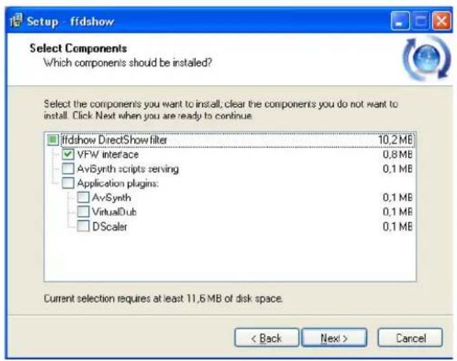
- Accept the default destination folder (ffdshow) or Browse to choose an alternative, Click Next to continue.

- Click to check the additional tasks that will be installed. For IPCamPlayer it is only necessary to use the default formats already selected. Click Next to continue.

- Click to check the video applications that use ffdshow. For IPCamPlayer it is only necessary to use the default applications already selected. Click Next to continue.

- Click to check the audio applications that use ffdshow. For IPCamPlayer it is only necessary to use the default applications already selected. Click Next to continue.
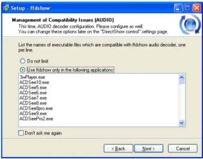
- Choose a speaker setup or choose Disable mixer if unsure. The audio function will work regardless of what speaker setup is chosen. Usually it will choose the default arrangement used on system on which it is being installed. Click Next to continue.

- Review the information and click Install if satisfied that it is correct to install the necessary codecs. The installation will take a few seconds.

- If desired, any of the three configuration utilities included with the ffdshow installation can be launched by checking the appropriate box. Click Finish to complete the installation.


NOTE: To download the latest copy of ffdshow please check the ffdshow website http://ffdshow.en.softonic.com/
9
Appendix
A. Frequently Asked Questions
Internet Camera Features
Q: What is an Internet Camera?
A: An Internet Camera is a stand-alone system connecting directly to an Ethernet or Fast Ethernet network and supported by the wireless transmission based on the IEEE 802.11b/g/n standard. It is different from the conventional PC camera, the camera is based on an all-in-one system with built-in CPU and web-based solutions providing a low cost solution that can transmit high quality video images for monitoring. The Camera can be managed remotely, accessed and controlled from any PC/Notebook over the Intranet or Internet via a web browser.
Q: What is the maximum number of users that are allowed to access the Camera simultaneously?
A: The maximum number of users that can log onto the Camera at the same time is 20. Please keep in mind the overall performance of the transmission speed will slow down when many users are logged on at the same time.
Q: What algorithm is used to compress the digital image?
A: The Camera utilizes JPEG image compression technology, providing a high quality image for users. JPEG has been adopted as it is a standard for image compression and can be applied to a variety of web browsers and software applications, avoiding the need to install additional application software.
Q: Can I change the wireless antenna attached to the Camera?
A: The wireless antenna can be changed for a variety of reasons, such as extending the wireless transmission range. However, please consult and authorized distributor before attempting this as the connectors must use an SMA connector type.
Q: What is the wireless transmission range for the Camera?
A: Generally the wireless signal can reach up to 100 meters indoors and up to 300 meters outdoors. The range is limited by the number of walls, ceilings or other objects that the wireless signals must pass through. Typical ranges vary depending on the types of materials and background Radio Frequency (RF) noise in your home or business and the configuration setting of your network environment.
Internet Camera Installation
Q: Can the Internet Camera be used outdoors?
A: The Camera is not water-proof and it is not recommended to use it outdoors. But you can use our Outdoor Internet Camera Enclosure TV-H500 or the one with Heater and Fan model TV-H510 to install the camera outdoor.
Q: What type of network cabling is required for the Camera?
A: The Camera uses Category 5 UTP cable allowing 10 Base-T and 100 Base-TX networking.
Q: Can the Camera be setup as a PC-cam on a computer?
A: No, the Camera is an Internet Camera used only on Ethernet and Fast Ethernet networks and supports wireless connections.
Q: Can the Camera be connected to the network if the LAN only consists of private IP addresses?
A: The Camera can be connected to a LAN with private IP addresses.
Q: Can the Camera be installed and work if a firewall exists on the network?
A: If a firewall exists on the network, port 80 should be open for ordinary data communication. However, since the Camera transmits image data, the default port 8481 is also required. Therefore, it is necessary to open 8481 on your firewall so that remote users can access the Camera.
B. PING your IP Address
The PING (Packet Internet Groper) command can determine whether a specific IP address is accessible by sending a packet to the specific address and waiting for a reply. It can also be a useful tool in confirming whether an IP address conflicts with the Camera's on the network.
To find out if the Camera conflicts with another IP address on the network follow the steps below:
- Disconnect the Camera from the network.
- Open a new DOS Window, by clicking Start > Run as shown below:
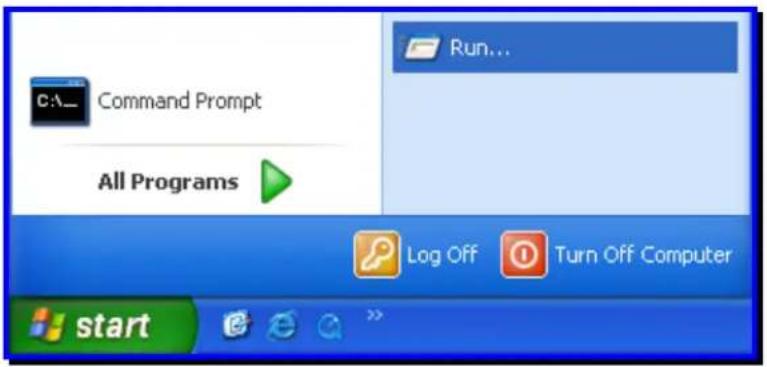
- Type cmd in the Run window:
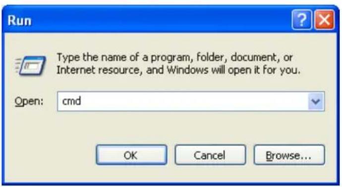
- Type ping x.x.x.x, where x.x.x.x is the IP address of the Camera, as shown below:

Reply messages indicate that there is another device on the network, as indicated in the above window.
C. Troubleshooting
Q: I cannot access the Camera from a web browser?
A1: The possible cause might by that the IP address of the Camera is already being used by another device. To correct the possible problem, you need to disconnect the Camera from the network first. Then run the PING utility (follow the instructions in Appendix B – PING your IP Address for more information).
A2: Another possible reason is the IP Address is located on a different subnet. To identify is this is the problem, run the PING utility (follow the instructions in Appendix B – PING your IP Address for more information). If the utility returns “no reply” message or similar, it is possible that your Camera is on a different subnet from your computer. Carry out the following:
A2.1: Open the Control Panel by clicking Start > Control Panel as shown below:

A2.2: Click the Network Connections icon as shown below:

A2.3: Double-click the network adaptor that is connected to your Camera:

Select TCP/IP from the "Network" dialog box and from the TCP/IP Properties:

Click the Properities button.

Double-click the Internet Protocol (TCP/IP) item and check that the first 3 bytes of your computer's IP address correspond with the first 3 bytes of the Camera's.
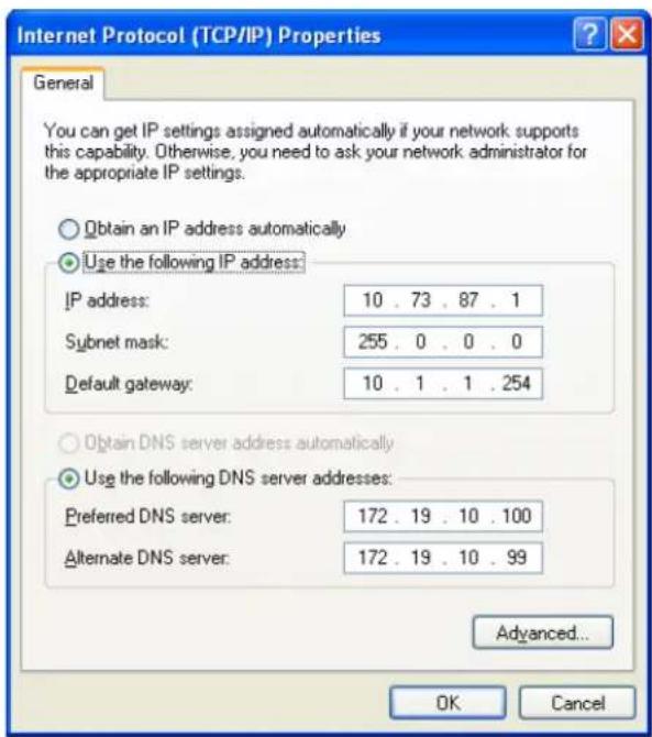
If the Camera is situated on a different subnet than your workstation, you will not be able to configure the Camera. Therefore, you must connect to the Camera from a PC on the same subnet to configure the Camera settings.
A3: The wireless connection might be faulty. If your Camera is operating in Ad-Hoc mode make sure the Camera wireless channel and SSID are set to match the PC/Notebook and the Camera must match with the Access Point's SSID.
Q: Why does the Camera work locally but not externally?
A1: The Camera's connection might be being blocked by a Firewall. Please check with your System Administrator to see if your Firewall allows access to the Camera.
A2: This could be caused by the Default Router setting. Double-check that the Camera's Default Router setting is correct.
Q: Why do a series of broad vertical white lines appear throughout the image?
A: A likely issue is that the CMOS sensor has become overloaded when the light source is too bright, such as direct exposure to sunlight or halogen light. You will need to reposition the Camera into a more shaded area immediately to avoid damaging the CMOS sensor.
Q: Noisy images occur, how can I resolve the problem?
A1: The video images might be noisy if the Camera is used in a very low light environment. To solve this issue you will need to increase the level of light in the Camera's location.
A2: There could be interference from other wireless devices on the network that are affecting the wireless transmission.
Q: There is poor image quality, how can I improve the image?
A1: A probable cause might be an incorrect property display configuration for your desktop. To check if this is the cause, open the Display Properties on your desktop and configure your display to show at least 65,000 colors, for example at least 16-bit.
A2: The configuration on the Camera image display is incorrect. Through the Web Configuration Image section you will need to adjust the image related parameters to improve the image, such as the brightness, contrast, hue and light frequency controls. Please refer to the Web Configuration section for more detailed information.
Q: There are no images available through the Web Browser?
A: ActiveX might be disabled. If your are viewing the images using Internet Explorer make sure ActiveX has been enabled in the Internet Options menu. Alternatively, you can use the Java Applet for viewing the required images.
D. Time Zone Table
| Time Zone Location/Description | |
| (GMT - 12:00) Enjwetok, Kwajalein | |
| (GMT - 11:00) | Midway Island, Samoa |
| (GMT - 10:00) | Hawaii |
| (GMT - 09:00) | Alaska |
| (GMT - 08:00) | Pacific Time (US & Canada; Tijuana) |
| (GMT - 07:00) | Arizona |
| (GMT - 07:00) | Mountain Time (US & Canada) |
| (GMT - 06:00) | Central Time (US & Canada) |
| (GMT - 06:00) | Mexico City, Tegucigalpa |
| (GMT - 06:00) | Saskatchewan |
| (GMT - 05:00) | Bogota, Lima, Quito |
| (GMT - 05:00) | Eastern Time (US & Canada) |
| (GMT - 05:00) Indiana (East) | |
| (GMT - 04:00) | Atlantic Time (Canada) |
| (GMT - 04:00) | Caracas, La Paz |
| (GMT - 04:00) | Santiago |
| (GMT - 03:30) | Newfoundland |
| (GMT - 03:00) | Brasilia |
| (GMT - 03:00) | Buenos Aires, Georgetown |
| (GMT - 02:00) | Mid-Atlantic |
| (GMT - 01:00) | Azores, Cape Verde Islands |
| (GMT) | Casablanca, Monrovia |
| (GMT) | Greenwich Mean Time: Dublin, Edinburgh, Lisbon, London |
| (GMT + 01:00) | Amsterdam, Berlin, Bern, Rome, Stockholm, Vienna |
| (GMT + 01:00) | Belgrade, Bratislava, Budapest, Ljubljana, Prague |
| (GMT + 01:00) | Brussels, Copenhagen, Madrid, Paris, Vilnius |
| (GMT + 01:00) | Sarajevo, Skopje, Sofija, Warsaw, Zagreb |
| (GMT + 02:00) | Athens, Istanbul, Minsk |
| (GMT + 02:00) | Bucharest |
| (GMT + 02:00) | Cairo |
| (GMT + 02:00) | Harare, Pretoria |
| (GMT + 02:00) | Helsinki, Riga, Talinn |
| (GMT + 02:00) Jerusalem | |
| (GMT + 03:00) | Baghdad, Kuwait, Riyadh |
| (GMT + 03:00) | Moscow, St. Petersburg, Volgograd |
| (GMT + 03:00) | Nairobi |
| (GMT + 03:30) | Tehran |
| (GMT + 04:00) | Abu Dhabi, Muscat |
| (GMT + 04:00) | Baku, Tbilisi |
| (GMT + 04:30) | Kabul |
| (GMT + 05:00) | Ekateringburg |
| (GMT + 05:00) | Islamabad, Karachi, Tashkent |
| (GMT + 05:30) | Bombay, Calcutta, Madras, New Delhi |
| (GMT + 06:00) Astana, Almaty, | Dhaka |
| (GMT + 06:00) | Colombo |
| (GMT + 07:00) | Bangkok, Hanoi, Jakarta |
| (GMT + 08:00) | Beijing, Chongqing, Hong Kong, Urumqi |
| (GMT + 08:00) | Perth |
| (GMT + 08:00) | Singapore |
| (GMT + 08:00) | Taipei |
| (GMT + 09:00) | Osaka, Sapporo, Tokyo |
| (GMT + 09:00) | Seoul |
| (GMT + 09:00) | Yakutsk |
| (GMT + 09:30) | Adelaide |
| (GMT + 09:30) | Darwin |
| (GMT + 10:00) | Brisbane |
| (GMT + 10:00) | Canberra, Melbourne, Sydney |
| (GMT + 10:00) | Guam, Port Moresby |
| (GMT + 10:00) Hobart | |
| (GMT + 10:00) | Vladivostok |
| (GMT + 11:00) | Magadan, Solomon Islands, New Caledonia |
| (GMT + 12:00) | Auckland, Wellington |
| (GMT + 12:00) | Fiji, Kamchatka, Marshall Islands |
E. Technical Specifications
| Camera | |
| General | Sensor: 1/4” CCD SensorFocal Length: f(wide) 3.8mm to f(tele) 38.0mmF/No: F(wide)=1.8 , F(tele) = 2.8LENS: Auto focus zoom lens with IR cut filterZoom Ratio: 10x optical zoom plus 16x digital zoomColor: full color or black and white modeDay & Night image modes: Automatic or scheduled transition between modesMinimum illumination: Color: 0.7 lux@F1.8 B/W: 0.02 lux@F1.8View:-Wide Angle:Horizontal: 51.3 degreeVertical: 39.3 degree-Max. Zoom Angle:Horizontal: 5.6 degreeVertical: 7.3 degree |
| Audio | Built-in omni-directional microphoneSensitivity: -40dB +/- 3dB (5 meters max.)Frequency: 100~20000HzS/N: >60dBCodec: ARM/PCM |
| Pan & Tilt | Pan: -165° ~ +165°Tilt: up 84° and down 31°Preset positions: 20Auto Patrol and manual controls |
| Image & Video | Compression: simultaneous H.264 / MPEG-4 / MJPEGProfiles: up to 4 profiles simultaneouslyIRIS Control /white balance control: automaticResolution: 704 x 480, 352 x 240, and 176 x 112 @ 30fps (NTSC)Resolution: 704 x 576, 352 x 288, and 176 x 144 @ 25fps (PAL)Built-in ICR |
| GPIO | Input: 1 setOutput: 1 set |
| Micro SD slot | Micro Secure Digital card (up to 16G) |
| Hardware | |
| Network | IEEE 802.3u 10/100Mbps Auto-MDIX Fast Ethernet |
| LED | Power, Link/Act |
| Reset Button | Reset to factory default |
| Power Consumption | 12 Watts (max.) |
| Power | 12V, 2A external power adapter |
| Dimension | 125 x 130 x 125 mm (4.9 x 5.1 x 4.9 in.) |
| Weight | Camera: 800 g (28.22 oz.) |
| Temperature | Operating: 0°C ~ 45°C (32°F ~ 113°F)Storage: -15°C ~ 60°C (5°F ~ 140°F) |
| Humidity | Max. 90% (non-condensing) |
| Certifications | CE, FCC |
| Requirement | |
| To View Camera | Internet Explorer 7.0 or above, Firefox 3.5 or above, Safari 4.0 or above |
| To Run Software | Windows 7 (32/64-bit), Vista (32/64-bit), XP (32/64-bit) |
| IPView Pro 2.0 | Channel: supports up to 32 camerasRecord/Playback/Motion Detection/Audio |
| Network Protocols | IPv4, ARP, TCP, UDP, ICMPDHCP Client, NTP Client, DNS Client, DDNS Client, SMTP Client, FTP ClientHTTPSamba ClientPPPoEUPnP RTP (Real Time Protocol)RTCP (Real Time Control Protocol)RTSP (Real Time Streaming Protocol) |
| Wireless (TV-IP612WN only) | |
| Standard | IEEE 802.11b, IEEE 802.11g, and IEEE 802.11n |
| Frequency | 2.4 ~ 2.497 GHz ISM band |
| Modulation | DQPSK, DBPSK, DSSS and CCKOFDM: BPSK, QPSK, 16QAM, 64QAM |
| Antenna | 2 x detachable 2dBi dipole antennas (Reverse-SMA connector) |
| Date Rate | 802.11b: up to 11Mbps802.11g: up to 54Mbps802.11n: up to 300Mbps |
| Security | 64/128-bit WEP, WPA/WPA2-PSK |
| Output Power | 802.11b: 18dBm (typical)802.11g: 15dBm (typical)802.11n: 13dBm ((typical) |
| Receiving Sensitivity | 802.11b: -85dBm at 11Mbps802.11g: -73dBm at 54Mbps802.11n: -65dBm at 300Mbps |
| Channels | 1~11 (FCC), 1~13(ETSI) |
| Management | |
| Accounts | Up to 20 user accounts |
| Remote Login | Remote management supported |
| Backup / Restore | Save/retrieve configuration files |
| Log | System log up to 1023 entries |
| Settings | |
| Image | Brightness, contrast, saturation, sharpness, white balance, flip, mirror (horizontal/vertical), black & white, day, night, schedule mode |
| Video Setting | Encoding Type: MJPEG / MPEG-4 /H.264- Resolution: 704 x 480, 352 x 240, 176 x112 (NTSC)- Resolution: 704 x 576, 352 x 288, 176 x144 (PAL)- Max. frame rate: 30 fps (NTSC) / 25fps (PAL) |
| Recording | Resolution: Define individual resolution for up to 4 profilesRequired storage: 32MB (minimum per profile)Recording type: event based (motion detection and digital input trigger), continuous, and scheduled |
| Snapshot | Trigger event: motion detection or digital input signalAction: send alert email and/or upload to FTPReal time snapshot |
| Port Settings | HTTP port: 80 (default)RTSP port: 554 (default) |
| Dynamic DNS | Yes |
| Time | Synchronize with NTP server or set time / date manually |
Limited Warranty
TRENDnet warrants its products against defects in material and workmanship, under normal use and service, for the following lengths of time from the date of purchase.
TV-IP612P / TV-IP612WN - 3 Years Warranty
Camera's motor, AC/DC Power Adapter, Cooling Fan, and Power Supply carry 1 year warranty.
If a product does not operate as warranted during the applicable warranty period, TRENDnet shall reserve the right, at its expense, to repair or replace the defective product or part and deliver an equivalent product or part to the customer. The repair/replacement unit's warranty continues from the original date of purchase. All products that are replaced become the property of TRENDnet. Replacement products may be new or reconditioned. TRENDnet does not issue refunds or credit. Please contact the point-of-purchase for their return policies.
TRENDnet shall not be responsible for any software, firmware, information, or memory data of customer contained in, stored on, or integrated with any products returned to TRENDnet pursuant to any warranty.
There are no user serviceable parts inside the product. Do not remove or attempt to service the product by any unauthorized service center. This warranty is voided if (i) the product has been modified or repaired by any unauthorized service center, (ii) the product was subject to accident, abuse, or improper use (iii) the product was subject to conditions more severe than those specified in the manual.
Warranty service may be obtained by contacting TRENDnet within the applicable warranty period and providing a copy of the dated proof of the purchase. Upon proper submission of required documentation a Return Material Authorization (RMA) number will be issued. An RMA number is required in order to initiate warranty service support for all TRENDnet products. Products that are sent to TRENDnet for RMA service must have the RMA number marked on the outside of return packages and sent to TRENDnet prepaid, insured and packaged appropriately for safe shipment. Customers shipping from outside of the USA and Canada are responsible for return shipping fees. Customers shipping from outside of the USA are responsible for custom charges, including but not limited to, duty, tax, and other fees.
WARRANTIES EXCLUSIVE: IF THE TRENDNET PRODUCT DOES NOT OPERATE AS WARRANTED ABOVE, THE CUSTOMER'S SOLE REMEDY SHALL BE, AT TRENDNET'S OPTION, REPAIR OR REPLACE. THE FOREGOING WARRANTIES AND REMEDIES ARE EXCLUSIVE AND ARE IN LIEU OF ALL OTHER WARRANTIES, EXPRESSED OR IMPLIED, EITHER FACT OR BY OPERATION OF LAW, STATUTORY OR OTHERWISE, INCLUDING WARRANTIES OF MERCHANTABILITY AND FITNESS FOR A PARTICULAR PURPOSE. TRENDNET NEITHER ASSUMES NOR AUTHORIZES ANY OTHER PERSON TO ASSUME FOR IT ANY OTHER LIABILITY IN CONNECTION WITH THE SALE, INSTALLATION MAINTENANCE OR USE OF TRENDNET'S PRODUCTS.
TRENDNET SHALL NOT BE LIABLE UNDER THIS WARRANTY IF ITS TESTING AND EXAMINATION DISCLOSE THAT THE ALLEGED DEFECT IN THE PRODUCT DOES NOT EXIST OR WAS CAUSED BY CUSTOMER'S OR ANY THIRD PERSON'S MISUSE, NEGLECT, IMPROPER INSTALLATION OR TESTING, UNAUTHORIZED ATTEMPTS TO REPAIR OR MODIFY, OR ANY OTHER CAUSE BEYOND THE RANGE OF THE INTENDED USE, OR BY ACCIDENT, FIRE, LIGHTNING, OR OTHER HAZARD.
LIMITATION OF LIABILITY: TO THE FULL EXTENT ALLOWED BY LAW TRENDNET ALSO EXCLUDES FOR ITSELF AND ITS SUPPLIERS ANY LIABILITY, WHETHER BASED IN CONTRACT OR TORT (INCLUDING NEGLIGENCE), FOR INCIDENTAL, CONSEQUENTIAL, INDIRECT, SPECIAL, OR PUNITIVE DAMAGES OF ANY KIND, OR FOR LOSS OF REVENUE OR PROFITS, LOSS OF BUSINESS, LOSS OF INFORMATION OR DATE, OR OTHER FINANCIAL LOSS ARISING OUT OF OR IN CONNECTION WITH THE SALE, INSTALLATION, MAINTENANCE, USE, PERFORMANCE, FAILURE, OR INTERRUPTION OF THE POSSIBILITY OF SUCH DAMAGES, AND LIMITS ITS LIABILITY TO REPAIR, REPLACEMENT, OR REFUND OF THE PURCHASE PRICE PAID, AT TRENDNET'S OPTION. THIS DISCLAIMER OF LIABILITY FOR DAMAGES WILL NOT BE AFFECTED IF ANY REMEDY PROVIDED HEREIN SHALL FAIL OF ITS ESSENTIAL PURPOSE.
Governing Law: This Limited Warranty shall be governed by the laws of the state of California.
Some TRENDnet products include software code written by third party developers. These codes are subject to the GNU General Public License ("GPL") or GNU Lesser General Public License ("LGPL").
Go to http://www.trendnet.com/gpl or http://www.trendnet.com Download section and look for the desired TRENDnet product to access to the GPL Code or LGPL Code. These codes are distributed WITHOUT WARRANTY and are subject to the copyrights of the developers. TRENDnet does not provide technical support for these codes. Please go to http://www.gnu.org/licenses/gpl.txt or http://www.gnu.org/licenses/lgpl.txt for specific terms of each license.
PWP05202009v2

TRENDNET®
Product Warranty Registration
Please take a moment to register your product online. Go to TRENDnet's website at http://www.trendnet.com/register
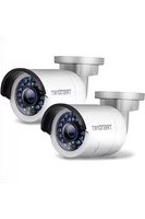
- ABOUT THIS USER'S GUIDE .... 1
- INTRODUCTION 2
- Camera Hardware Components 6
- INSTALLING THE CAMERA....9
- SECURITY 12
- APPLICATION....13
- USING THE UTILITY 14
- SetupWizard 14
- USING THE CAMERA WEB MANAGER....30
- Accessing the Camera Video Display 30
- Wizard 32
- System 36
- Network 38
- Video Audio 41
- Action 45
- Motion Detection 51
- Tools....52
- Device Info....53
- Viewing Video....54
- IPVIEW PRO 2.0 ....57
- Launching IPView Pro 2.0 for the first time ....57
- IPView Pro 2.0 User Interface....60
- PLAYING VIDEO FILES ON A COMPUTER....71
- Load Saved Video Files....72
- Play Video Files....73
- ffdshow 74
- APPENDIX 80
- About This User's Guide
- Introduction
- Features and Benefits
- Unpacking the Package
- System Requirements
- Networking
- Computer
- Default Settings
- Camera Hardware Components
- Front Panel Components
- LED Indicators
- Rear Panel Components
- Installing the Camera
- Attach the Metal Plate
- Connect Ethernet Cable
- Connect Power and Power On Camera
- Reset Camera
- Security
- Application
- Using the Utility
- SetupWizard
- Installing the SetupWizard
- Launching the SetupWizard
- SetupWizard- Install Your Camera
- SetupWizard- Select Your Camera
- SetupWizard- Authentication
- SetupWizard- Other Settings
- SetupWizard- Change Password
- SetupWizard- Select a Connection Option
- SetupWizard – Select a Connection Option - PPPoE
- SetupWizard- Select a Connection Option- DHCP
- SetupWizard- Select a Connection Option- Fixed IP
- SetupWizard- Setup Wireless (For TV-IP612WN only)
- SetupWizard- Setting Up The Camera
- SetupWizard- Camera Restart
- SetupWizard- Complete
- Using the Camera Web Manager
- Accessing the Camera Video Display
- Login
- Setup - Web Configuration Utility
- Wizard
- System menu in Administration directory
- Step 1 Setup LAN Settings
- Step 2 Setup Internet Settings
- Step 3 Setup DDNS Settings
- Step 4 Camera Name Settings
- Step 5 Setup Time Zone
- Step 6 Setup Complete
- System
- Device Management
- Admin Password Settings:
- Add User Account:
- User List:
- Device Settings:
- Calibrate the Device
- Time and Date
- Time Configuration
- Automatic Time Configuration
- Set date and time manually
- Network
- Network Setup
- Port Settings
- Direct Video Stream Authentication
- Wireless Setup
- Enable Wireless: Check this box to enable the wireless network connection mode of the camera
- Selecting a SSID from the Site Survey
- Dynamic Domain Name Service (DDNS)
- Video Audio
- Video and Audio
- Video Profile 1-4
- Notes
- Audio Setup
- Image Setup
- Advance Image Settings
- Preferred Mode:
- Shutter Mode (Shutter-preferred)
- ICR
- Action
- Recording
- Recording Options
- Scheduling
- Event Based: Click this setting to use event based triggering
- Snapshot
- Email Settings
- FTP Settings
- Preset Position
- Camera Control
- Digital Output
- External Digital Input/Output Connectors
- Digital I/O Terminal Block Description
- Trigger
- Trigger Event
- D/I Signal 1
- Motion Detection
- Live Video
- Drawing Mode:
- Draw motion area:
- Motion Detection Indicators
- Tools
- Backup and Restore
- Firmware Upgrade
- Device Info
- Log
- Viewing Video
- Controlling the Camera
- IPView Pro 2.0
- Launching IPView Pro 2.0 for the first time
- Add a camera for monitoring
- IPView Pro 2.0 User Interface
- Display Controls
- Snapshot, recording and audio controls
- Live video display controls
- Camera configuration with IPView Pro 2.0
- Adding a Camera – Camera management
- To add a camera:
- Removing a Camera
- Launch Web Manager for Selected Camera
- Schedule Recording with IPView Pro 2.0
- Create Schedule Templates
- Setup Motion Detection and Digital Input with IPView Pro 2.0
- IPView Pro 2.0 Recording Options
- IPView Pro 2.0 Miscellaneous Options
- Playing Video Files on a Computer
- Load Saved Video Files
- Play Video Files
- ffdshow
- Install ffdshow
- Appendix
- Frequently Asked Questions
- Internet Camera Features
- Internet Camera Installation
- PING your IP Address
- Troubleshooting
- Limited Warranty
- TRENDNET®
- Product Warranty Registration
Brand : TRENDNET
Model : TV-IP612P
Category : Security Camera