DCU105 - Gps ECLIPSE - Free user manual and instructions
Find the device manual for free DCU105 ECLIPSE in PDF.

| Product Type | GPS Navigation Device |
| Brand | Eclipse |
| Model | DCU105 |
| Display Size | 4.3 inches |
| Display Resolution | 480 x 272 pixels |
| Dimensions (W x H x D) | 120 x 80 x 20 mm |
| Weight | 150 g |
| Power Source | Built-in rechargeable lithium-ion battery |
| Battery Life | Up to 4 hours |
| Charging | USB cable (5V/1A) |
| Internal Memory | 4 GB |
| Expandable Memory | microSD card up to 32 GB |
| GPS Chipset | MediaTek MT3333 |
| Maps | Preloaded with regional maps |
| Route Guidance | Turn-by-turn voice navigation |
| Points of Interest (POI) | Yes, integrated database |
| Connectivity | USB 2.0 |
| Mounting | Suction cup windshield mount |
| Languages | Multiple languages supported |
| Cleaning | Wipe with a soft, dry cloth |
| Operating Temperature | 0°C to 60°C |
| Safety | Do not immerse in water; keep away from moisture |
| Repairability | Battery and microSD slot user-accessible; other repairs by qualified technician |
Frequently Asked Questions - DCU105 ECLIPSE
User questions about DCU105 ECLIPSE
0 question about this device. Answer the ones you know or ask your own.
Ask a new question about this device
Download the instructions for your Gps in PDF format for free! Find your manual DCU105 - ECLIPSE and take your electronic device back in hand. On this page are published all the documents necessary for the use of your device. DCU105 by ECLIPSE.
USER MANUAL DCU105 ECLIPSE
5.1ch Decoder/AV Matrix Unit
DCU105
MODEL
INSTALLATION MANUAL
Be sure to read this installation manual thoroughly prior to installation and making connections. If installation methods or non-standard parts not specified in this installation manual are used, accidents or injury may result.
Professional installation is recommended, contact the place of purchase to schedule an appointment. After reading the owner's manual and the installation manual thoroughly, keep them in a safe place for future reference.
To dealers:
Give this installation manual to the customer after installation and all connections have been completed.

ontents
Before installation
Components 2
For your safety in using the DCU105 3
Connections
Names and functions of terminals 5
Speaker connection examples 8
Installation
Installing the decoder unit 9
When measuring frequency response characteristics or carrying out automatic time alignment inside the vehicle 10
natural_image
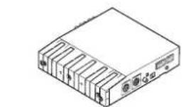
Line drawing of a rectangular electronic device with multiple ports and an external control panel (no text or symbols)① Decoder unit x 1

② Interconnecting cable (Power and speaker connector) (16P) x 1

③ Interconnecting cable (12P) x 1

④ Interconnecting cable (20P) x 1

⑤ Side bracket x 2

⑥ Self-adhesive pad x 2

⑦ Hex-head bolt
(Red:M5x8) x 4
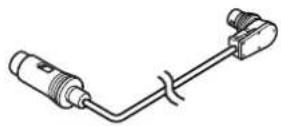
⑧ DIN cable (13P) x 1
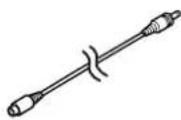
⑨ Digital RCA cable
(Black)
(3.5m) x 1
natural_image
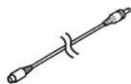
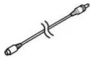
Pure electrical circuit lines without any symbols⑩ VTR RCA cable (3.5m)x 1
⑪ Monophonic RCA cable
(White)
(3.5m) x 1
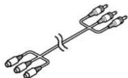
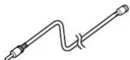
⑫ Video input cable
(Yellow)
(3.5m) x 1
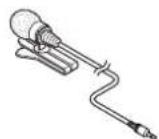
⑬ Microphone for measuring frequency characteristics x 1
⑭ microphone extension cable
(4m) x 1
Warnings and caution signs, illustrated bellow, are posted throughout this manual as well as on the DCU105. They show safe and correct ways to handle the product to prevent personal injury to you and others and avoid damage to property.
When reading through the manual, take the time to read through and learn the important information listed in this section.


This "WARNING" sign indicates a situation in which incorrect handling may result in death or serious personal injury.
This "CAUTION" sign indicates a situation in which incorrect handling may result in personal injury or may result solely in damage to property.

Tip
This section contains information that can help to prevent problems and damage to the unit, and also contain other useful information.
⚠ Warning
- Do not install this product in locations where it may obstruct the driver's view, or where it may endanger passengers in the vehicle. Otherwise, an accident or injury may result.
- Do not install this product in locations where it may interfere with the operation of the steering wheel, shift lever, brake pedal, etc. Otherwise, an accident or injury may result.
• To prevent damage to the vehicle, confirm the locations of hoses, electrical wiring, and the fuel tank prior to drilling holes to install this product. Also, take all necessary precautions so that the product does not interfere, nor come in contact with them. Otherwise, a fire may result. - When installing this product, never use the existing nuts or bolts that secure parts of the fuel tank, the steering, or braking systems. Otherwise, improper steering or braking and / or a fire may result.
• To prevent a short circuit from occurring, disconnect the battery's negative terminal prior to installing this product. Otherwise, an electric shock or injury may result. - When using an existing nut and/or bolt from the vehicle to ground this product, do not use any that secure parts of the steering or braking systems. Otherwise, an accident may result.
-
Bundle cables and harnesses with electrical tape or wire ties to prevent them from interfering with moving parts. If they should entangle with the steering wheel, shift lever or brake pedal, an accident may result.
-
Never supply power to another electrical appliance by splicing or tapping into this product's power lead (battery supply or constant power wire). Otherwise, the current capacity of the wire will be exceeded, resulting in a fire or electric shock.
- Never attempt to disassemble or modify the product. Otherwise, an accident, fire or electric shock may result.
- When replacing fuses, be sure to use fuses of the specified capacity (amperage). Otherwise, damage to the unit, fire, or an electric shock may result.
- When installing the product into a vehicle with a passenger side air bag, never install or secure the product to the air bag's cover or in places where it may impede air bag deployment. Otherwise, proper air bag operation may not be ensured in the event of an accident, causing injury or death.
- When making holes using drill or similar tool, be sure to wear protective eyewear. Otherwise, an injury such as loss of eyesight may result.
- Exposed wires must be insulated with electrical tape. Otherwise, a short circuit, fire, or electric shock may result.
- Do not modify this system for use other than that specified herein. Also, do not deviate from the installation procedures described herein; Eclipse will not be held liable for damages including, but not limited to serious injury, death or property damage resulting from installations that enable unintended operation.
Caution
- For best results, this product should be installed by a professional installer.
Contact the dealer whom you purchased the product for an appointment. - When installing this product, be sure to use the supplied mounting hardware. If parts other than those supplied are used, the unit may be damaged internally, or may not be held in place securely and become dislodged.
- Avoid installing this product in places where it may get wet, such as near windows, or in places that are moist, damp, or dusty. Presence of liquid, moisture, or dust inside this product can cause short circuiting resulting in smoke and / or fire.
- If this product is not connected properly, a short circuit, fire, and / or accident may occur.
-
When routing cables, use care so that they do not contact sharp metal parts such as brackets or screw tips. Otherwise, a short circuit, electric shock, fire and / or accident may result.
-
Play the audio at a moderate volume level that permits you to hear sounds from outside the vehicle. Driving with the inability to not hear outside sounds may result in an accident.
• This product must be operated only as on-board equipment, or it may cause electrical shock or injury. - Do not play distorted sounds for long periods of time; the speakers may overheat and cause a fire.
- Do not cover the ventilation holes or the cooling plate of the product. If the ventilation holes or cooling plate are covered, heat will build up inside the product and fire may result.
- Do not clean the cables or cords with volatile chemicals such as alcohol, kerosene, thinner or gasoline. Using such chemicals may cause warping, discoloration or other damage.

Names and functions of terminals
Warning
- Never cut the insulation on the power cable or use it to power any other equipment. If the rated current capacity of the power cable is exceeded, fire and electric shocks may result.
• The cables should be secured with tape or similar securing method so that they will not cause an obstruction while driving. If they get wound or entangled around components such as the steering wheel, shifting lever, or brake pedal, accidents may result.
text_image
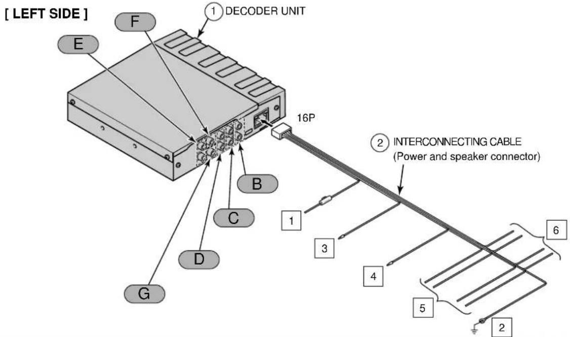
[ LEFT SIDE ] E F 1 DECODER UNIT 16P 2 INTERCONNECTING CABLE (Power and speaker connector) 1 3 4 5 6 2 D C B G[ RIGHT SIDE ]
text_image
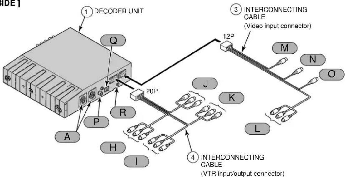
SIDE] 1 DECODER UNIT Q P A R H I 20P J K L M N O 3 INTERCONNECTING CABLE (Video input connector) 4 INTERCONNECTING CABLE (VTR input/output connector)
Tip
• Refer to page 6 for details on the wire colors and connection points for interconnecting cables ②
• Refer to page 6 and 7 for details on connection points A through R for the main unit cables and terminals.
◆Wire colors and connection points for connection cables ②

Never connect the power supply to the speaker leads (No.5 and No.6), otherwise it will cause damage to the main unit.
1 B+ (Yellow)
Connect where the power is constantly available, regardless of the ignition key's position.
2 Ground (Black)
Connect where good body grounding is available.
3 DVD MUTE wire (Pink)
Connect to H/A MUTE or DVD MUTE on the main unit.
4 NAVI MUTE wire (Brown)
Connect to NAVI MUTE on the navigation unit.
If not using and, insulate
them using PVC tape or similar.
If they are not insulated, incorrect operation may result.
5 Front speaker output leads
Connect to the front speakers.
White: Left + White/Black: Left -
Gray: Right + Gray/Black: Right -
6 Rear speaker output leads
Connect to the rear speakers.
Green: Left + Green/Black: Left -
Purple: Right + Purple/Black: Right -
◆Main unit connections
A E-LAN terminal
Connect to the main unit or to a CD changer (sold separately) if one is being used with the system.
B Line-out terminal (Front Mid-Low)
C Line-out terminal (Front / Front Mid)
Connect to the RCA input Connectors of an external amplifier.
White : Left signal
Red : Right signal
D Line-out terminal (Front Hi)
* The speakers to connect will vary depending on whether the speaker layout is . 1-way speaker . or . 3-way speaker. (Refer to the instruction manual for details on switching the speaker layout.)
• If the speaker layout is "1-way speaker":
Use the "LINE OUT" (Front/Front/Mid) terminal C.
Terminals B and D are not used.
• If the speaker layout is "3-way speaker":
Connect B to the low-range speaker (woofer), connect C to the mid-range speaker (squawker), and connect D to the high-range speaker (tweeter).
E Line-out terminal (Rear)
Connect to the RCA input Connectors of an external amplifier.
White : Left signal
Red : Right signal
F
Center speaker line-out terminal
If using a center speaker (sold separately), connect it to the RCA input connector of an external amplifier.
G
Woofer speaker line-out terminal
If using a woofer speaker (sold separately), connect it here.
H
VTR input terminals (CH1)

Connect the output cable of external video equipment such as a VTR.
Yellow : Video signal
White : Audio (left) signal
Red : Audio (right) signal
|
VTR input terminals (CH2)

Connect to the monitor's video input.
Yellow : Video signal
White : Audio (left) signal
Red : Audio (right) signal
J
VTR output terminals (CH1)
K
VTR output terminals (CH2)
L
Video input terminal
Connect to the AV output terminal of the main unit.
Yellow : Video signal
White : Audio (left) signal
Red : Audio (right) signal
M
NAVI-VOICE input terminal
Connect to the NAVI sound volume output terminal of the main unit.
N
Video output terminal
Connect to the video input terminal of the main unit.
O
Digital input terminal
Connect to the digital output terminal of the main unit.
P
RCA digital input terminal (DIGITAL 1)
Q
Optical digital input terminal (DIGITAL 2)
R
MIC terminal 3.5 mm mini-jack
If measuring frequency response characteristics or carrying out automatic time alignment, connect the accessory measuring microphone here.
If not connecting an external amplifier (sold separately)
text_image
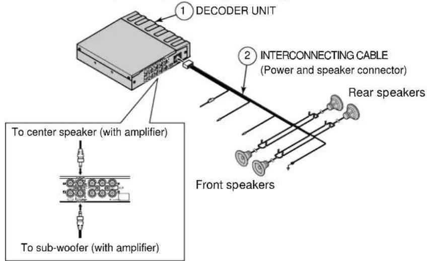
① DECODER UNIT ② INTERCONNECTING CABLE (Power and speaker connector) Rear speakers Front speakers To center speaker (with amplifier) To sub-woofer (with amplifier)For a front 1-way speaker system
text_image
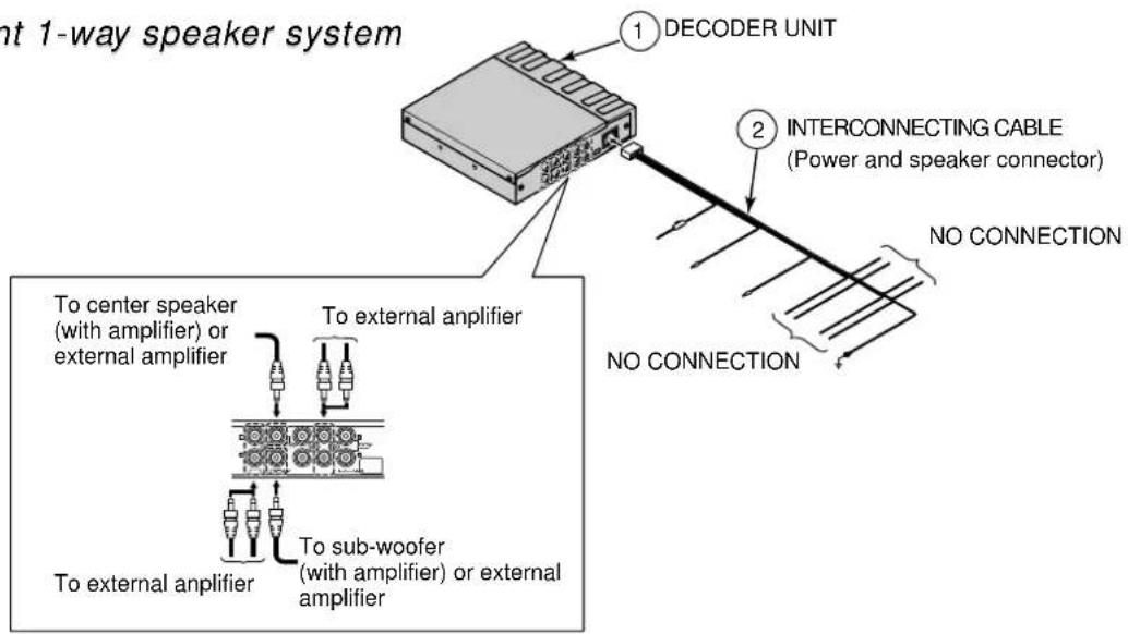
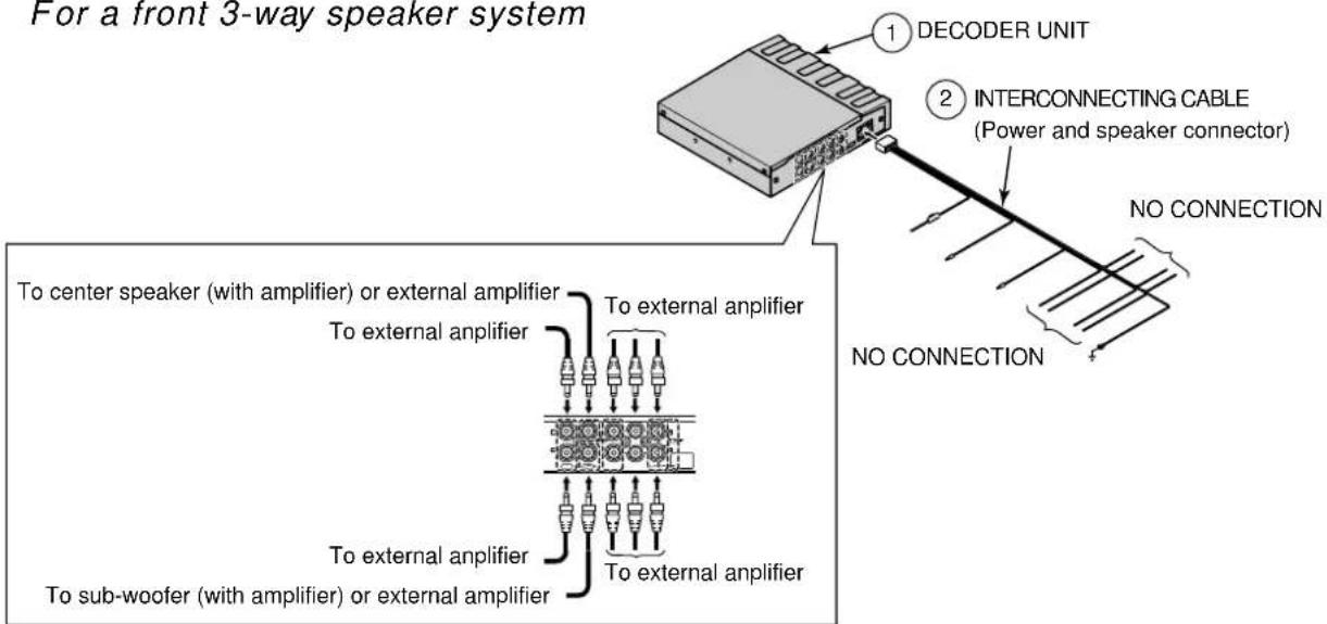
nt 1-way speaker system ① DECODER UNIT ② INTERCONNECTING CABLE (Power and speaker connector) NO CONNECTION NO CONNECTION To center speaker (with amplifier) or external amplifier To external amplifier To sub-woofer (with amplifier) or external amplifierFor a front 3-way speaker system
text_image
For a front 3-way speaker system ① DECODER UNIT ② INTERCONNECTING CABLE (Power and speaker connector) NO CONNECTION No CONNECTION To center speaker (with amplifier) or external amplifier To external amplifier To external amplifier To sub-woofer (with amplifier) or external amplifier To external amplifierInstalling the decoder unit
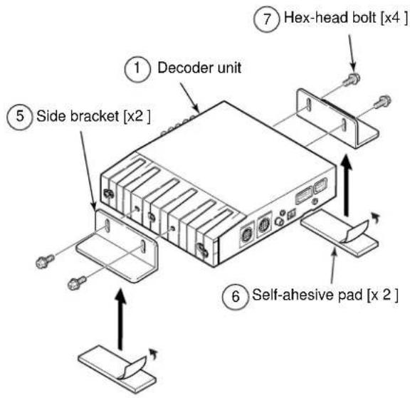
1 Install the side brackets to the sides of the decoder unit with the supplied screws.
2 Attach the self-adhesive pads to the base of the side brackets.
3 Life up the carpet underneath the vehicle seat and find a suitable mounting location.
text_image
① Decoder unit ⑤ Side bracket [x2] ⑥ Self-ahesive pad [x 2] ⑦ Hex-head bolt [x4]4 Make marks on the floor to indicate the bracket mounting location.
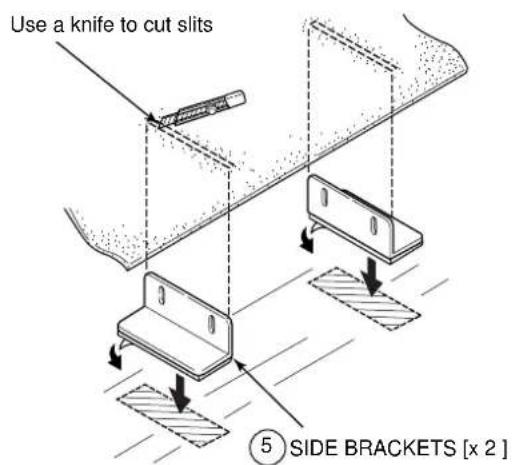
5 Remove the side brackets from the decoder unit, and attach the side brackets to the floor at the indicated mounting location.
6 Use a knife to cut slits in the carpet at positions corresponding to the top of the brackets.
text_image
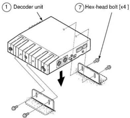
Use a knife to cut slits ⑤ SIDE BRACKETS [x 2 ]7 Install the decoder unit to the side brackets.
text_image
① Decoder unit ⑦ Hex-head bolt [x4 ]When measuring frequency response characteristics or carrying out automatic time alignment inside the vehicle
1 Connect the accessory measuring microphone to the decoder unit.
2 Install the microphone to the headrest of the driver's seat.

Tip
- Using the supplied velcro strap, secure the microphone to the base of the headrest.
• Refer to the owners manual of the main unit for the correct procedures when taking measurements.
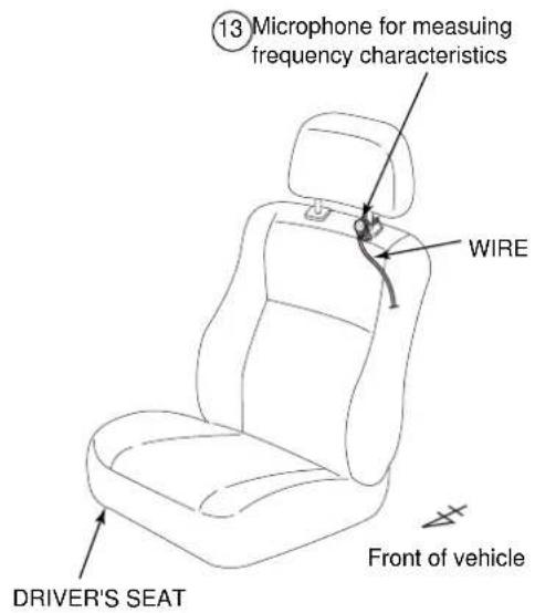
text_image
⑬ Microphone for measuring frequency characteristics WIRE DRIVER'S SEAT Front of vehicle"ECLIPSE" is a registered trademark of FUJITSU TEN LIMITED in 48 countries including the U.S. and Japan.
090003-28580700 0507DE (CN)