
F-X88ZL - Hi-Fi System PIONEER - Free user manual and instructions
Find the device manual for free F-X88ZL PIONEER in PDF.

| Product Type | Hi-Fi System (Double Cassette Deck, Turntable, FM/AM/LW Tuner) |
| Brand | Pioneer |
| Model | F-X88ZL |
| Amplifier Power Output | 50 W + 50 W continuous (1 kHz, 8 ohms, 1% THD) |
| Graphic Equalizer | 5 bands (100 Hz, 330 Hz, 1 kHz, 3.3 kHz, 10 kHz), ±7 dB |
| Tape Deck Configuration | Double deck: Deck I playback only, Deck II record/playback |
| Tape Copy Functions | High Speed Copy, Normal Speed Copy, Synchronized Rec Start |
| Wow and Flutter (Tape) | ≤0.13% (WRMS) |
| Frequency Response (Tape, Normal) | 35 Hz – 14 kHz ±6 dB |
| Noise Reduction | Dolby B NR |
| Tuner Type | Digital synthesizer FM/AM (LW on F-X88ZL) |
| Preset Stations | 24 (FM and AM/LW) |
| FM Sensitivity | 12.7 dBf (IHF) |
| AM Sensitivity | 350 µV/m (loop antenna) |
| Turntable Drive | Belt drive |
| Turntable Speeds | 33 1/3 and 45 rpm |
| Turntable Wow and Flutter | 0.05% (WRMS) |
| Turntable Signal-to-Noise Ratio | 68 dB (DIN-B) |
| Cartridge | MM type, replacement stylus PN-295T |
| Power Consumption | 210 W |
| Power Requirements | AC 220–240 V, 50/60 Hz (depending on region) |
| Amplifier Dimensions (W x H x D) | 360 x 190 x 283 mm |
| Amplifier Weight | 6.8 kg |
| Tuner Dimensions (W x H x D) | 360 x 56 x 215 mm |
| Tuner Weight | 1.8 kg |
| Turntable Dimensions (W x H x D) | 360 x 96.5 x 384 mm |
| Turntable Weight | 3.2 kg |
| Accessories Included | AM loop antenna, FM T-type antenna, 45 rpm adaptor, turntable legs |
| Maintenance | Head cleaning, demagnetizing, stylus replacement |
| Safety Features | Polarized plug, voltage selector, auto-stop mechanism |
Frequently Asked Questions - F-X88ZL PIONEER
User questions about F-X88ZL PIONEER
0 question about this device. Answer the ones you know or ask your own.
Ask a new question about this device
Download the instructions for your Hi-Fi System in PDF format for free! Find your manual F-X88ZL - PIONEER and take your electronic device back in hand. On this page are published all the documents necessary for the use of your device. F-X88ZL by PIONEER.
USER MANUAL F-X88ZL PIONEER
Thank you for buying this Pioneer product.
Please read through these operating instructions so you will know how to operate your model properly. After you have finished reading the instructions, put them away in a safe place for future reference.
In some countries or regions, the shape of the power plug and power outlet may sometimes differ from that shown in the explanatory drawings. However, the method of connecting and operating the unit is the same.
IMPORTANT NOTICE
[For U.S. and Canadian models]
The serial number for this equipment is located on the rear panel. Please write this serial number on your enclosed warranty card and keep it in a secure area. This is for your security.
[For Canadian model]
CAUTION: TO PREVENT ELECTRIC SHOCK DO NOT USE THIS (POLARIZED) PLUG WITH AN EXTENSION CORD, RECEPTACLE OR OTHER OUTLET UNLESS THE BLADES CAN BE FULLY INSERTED TO PREVENT BLADE EXPOSURE.
ATTENTION: POUR PREVENIR LES CHOCS ELECTRIQUES NE PAS UTILISER CETTE FICHE POLARISEE AVEC UN PROLONGATEUR UNE PRISE DE COURANT OU UNE AUTRE SORTIE DE COURANT, SAUF SI LES LAMES PEUVENT ETRE INSEREES A FOND SANS EN LAISSER AUCUNE PARTIE A DECOUVERT.
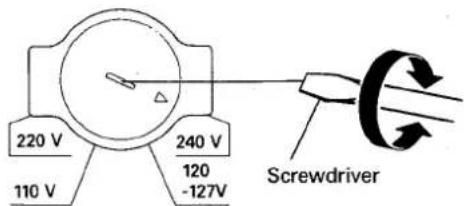
LINE VOLTAGE SELECTOR SWITCH
Only multi-voltage models are provided with this switch. U.S., Canadian, European, U.K., and Australian models are not provided with this switch.
Before your model is shipped from the factory, the switch is set to the power requirements of the destination; nevertheless, you should check that it is set properly before plugging the power cord into the AC outlet.
- Disconnect the power cord.
- Use a medium-size screwdriver.
- Insert the screwdriver into the groove on the voltage selector and adjust to the voltage value of your area so that the tip of the arrow point.
These operating instructions cover all the models above. Refer to the items corresponding to your model.
"This product is manufactured to comply with the radio interference requirements of EEC Directive 76/889/EEC and 82/499/EEC."
WARNING: TO PREVENT FIRE OR SHOCK HAZARD. DO NOT EXPOSE THIS APPLIANCE TO RAIN OR MOISTURE.
CONTENTS
Features 3
Checking the accessories 3
Initial turntable set-up 3
Connections 4
Antenna connection 5
Front panel facilities 6
How to handle cassette tapes 10
Graphic equalizer controls.... 11
Basic operations.... 11
Recording and playback using the audio timer ..... 15
Maintenance 16
Troubleshooting....17
Specifications 18
SAFETY INSTRUCTIONS
READ INSTRUCTIONS — All the safety and operating instructions should be read before the appliance is operated.
RETAIN INSTRUCTIONS - The operating instructions should be retained for future reference.
HEED WARNING — All warnings on the appliance and in the operating instructions should be adhered to.
FOLLOW INSTRUCTIONS — All operating and use instructions should be followed.
WATER AND MOISTURE — The appliance should not be used near water — for example, near a bathtub, washbowl, kitchen sink, laundry tub, in a wet basement, or near a swimming pool, etc.
LOCATION — The appliance should be installed in a stable location.
WALL OR CEILING MOUNTING — The appliance should not be mounted to a wall or ceiling.
VENTILATION - The appliance should be situated so that its location or position does not interfere with its proper ventilation. For example, the appliance should not be situated on a bed, sofa, rug, or similar surface that may block the ventilation openings; or, placed in a built-in installation, such as a bookcase or cabinet that may impede the flow of air through the ventilation openings.
HEAT — The appliance should be situated away from heat sources such as radiators, heat registers, stoves, or other appliances (including amplifiers) that produce heat.
POWER SOURCES — The appliance should be connected to a power supply only of the type described in the operating instructions or as marked on the appliance.
POWER-CORD PROTECTION - Power-supply cords should be routed so that they are not likely to be walked on or pinched by items placed upon or against them, paying particular attention to cords at plugs, convenience receptacles, and the point where they exit from the appliance.
POLARIZATION — If your purchased product is provided with a polarized power plug, please read the following instructions. This product is equipped with a polarized alternating current line plug (a plug having one blade wider than the other). This plug will fit into the power outlet only one way. This is a safety feature. If you are unable to insert the plug fully into the outlet, try reversing the plug. If the plug should still fail to fit, contact your electrician to replace your obsolete outlet. Do not defeat the safety purpose of the polarized plug.
CLEANING — The appliance should be cleaned only with a polishing cloth or a soft dry cloth. Never clean with furniture wax, benzine, insecticides or other volatile liquids since they may corrode the cabinet.
POWER LINES — An outdoor antenna should be located away from power lines.
NONUSE PERIODS — The power cord of the appliance should be unplugged from the outlet when left unused for a long period of time.
OBJECT AND LIQUID ENTRY — Care should be taken so that objects do not fall and liquids are not spilled into the enclosure through openings.
DAMAGE REQUIRING SERVICE — The appliance should be serviced by Pioneer authorized service center or qualified service personnel when:
- The power-supply cord or the plug has been damaged; or
- Objects have fallen, or liquid has been spilled into the appliance; or
• The appliance has been exposed to rain; or
• The appliance does not appear to operate normally or exhibits a marked change in performance; or
- The appliance has been dropped; or the enclosure damaged.
SERVICING - The user should not attempt to service the appliance beyond that described in the operating instructions. For all other servicing, contact the nearest Pioneer authorized service center.
OUTDOOR ANTENNA GROUNDING — If an outside antenna is connected to the antenna terminal, be sure the antenna system is grounded so as to provide some protection against voltage surges and built up static charges.
In the U.S.A. section 810 of the National Electrical Code, ANSI/NFPA No. 70-1984, provides information with respect to proper grounding of the mast and supporting structure, grounding of the lead-in wire to an antenna discharge unit, size of grounding conductors, location of antenna-discharge unit, connection to grounding electrodes, and requirements for the grounding electrode. See Fig. A.
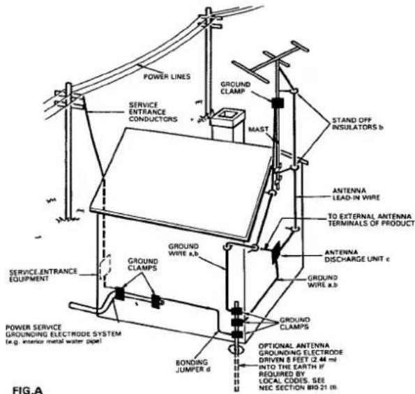
a) Use No. 10 AWG (5.3 mm ^2 ) copper, No. 8 AWG (8.4 mm ^2 ) aluminum, No. 17 AWG (1.0 mm ^2 ) copper-clad steel, bronze wire, or larger as ground wire.
b) Secure antenna lead-in and ground wires to house with stand-off insulators spaced from 4 feet (1.22 meters) to 6 feet (1.83 meters) apart.
c) Mount antenna discharge unit as closely as possible to where lead-in enters house.
d) Use jumper wire not smaller than No.6 AWG (13.3 mm²) copper or equivalent when separate antenna-grounding electrode is used.
IMPORTANT 1

The lightning flash with arrowhead, within an equilateral triangle, is intended to alert the user of the presence of uninsulated "dangerous voltage" within the product's enclosure that may be of sufficient magnitude to constitute a risk of electric shock to persons.
CAUTION
RISK OF ELECTRIC SHOCK DO NOT OPEN
CAUTION:
TO PREVENT THE RISK OF ELECTRIC SHOCK, DO NOT REMOVE COVER (OR BACK). NO USER-SERVICEABLE PARTS INSIDE. REFER SERVICING TO QUALIFIED SERVICE PERSONNEL.

The exclamation point within an equilateral triangle is intended to alert the user of the presence of important operating and maintenance (servicing) instructions in the literature accompanying the appliance.
IMPORTANT 2
If the apparatus is fitted with AC mains power outlet(s), see REAR PANEL FACILITIES for convenient connection of additional Hi-Fi component(s). Make all connections to the AC outlet(s) and the signal terminals first. Connect the plug to the wall socket last, make sure that the power switch is off. Disconnect the wall plug when the equipment is not in (regular) use, e.g. when on vacation.
FOR USE IN THE UNITED KINGDOM
The wires in this mains lead are coloured in accordance with the following code:
Blue:
Neutral
Brown:
Live
As the colours of the wires in the mains lead of this apparatus may not correspond with the coloured marking identifying the terminals in your plug proceed as follows:
The wire which is coloured blue must be connected to the terminal which is marked with the letter N or coloured black.
The wire which is coloured brown must be connected to the terminal which is marked with the letter L or coloured red.
Equipment sold in the U.K. is not supplied with a power plug.
FEATURES
Double deck configuration
The double deck configuration, with one deck for playback only and the other for both recording and playback, provides lots of fun with its double speed copying and relay play functions.
5-control graphic equalizer
The graphic equalizer with its 5 controls allows the listener to adjust the sound quality optimally.
24-station random FM/AM presetting (F-X88Z, F-X88ZL)
A total of up to 24 FM and AM stations can be preset in order to facilitate instant recall of your favorite stations in areas where the frequency bands are crowded with stations. On models provided with the LW tuning band, a total of 24 FM, MW and LW stations can be preset.
FM MONO switch (F-X88Z, F-X88ZL)
When the FM MONO switch is set to on, those stereo broadcasts that are drowned out by noise can be tuned in with greater clarity. The FM MONO reception mode can be preset for individual broadcasting stations.
CHECKING THE ACCESSORIES
Cassette deck amplifier
Turntable legs ... 2
Screws 2
FM/AM Tuner
AM loop antenna
1
T-type antenna ..... 1
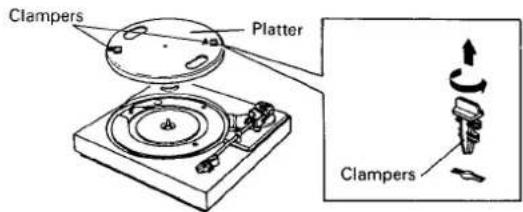
INITIAL TURNTABLE SET-UP
- Check accessory items and attaching pieces.

EP Adaptor

Platter mat
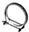
- Remove the 2 clampers and lift off the platter. To remove the clampers, twist them in the direction indicated in the illustration, and lift them straight up.
-
Hook the turntable drive belt over your finger.
-
Set the platter onto the turntable so that the platter shaft passes through it. Hook the drive belt over the motor pulley. Rotate the platter a few times by hand to make sure that the belt is correctly in place.
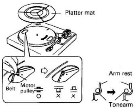
- Place the platter mat on top of the platter.
- Remove the band securing the tonearm.
- Disconnect the tonearm from the arm rest.
- Remove the stylus guard.
Proceed as follows with the set-up and connections.
- Place the tuner on top of the cassette tape deck amplifier.
- Connect the tuner input/output cord to cassette tape deck amplifier.
- Connect the FM antenna and the AM antenna to the tuner's antenna terminals. (See page 5) If the model has an AM/FM CHANNEL STEP switch, check whether it is positioned properly. (See page 5)
-
Attach the turntable legs at the left and right of the cassette tape deck amplifier's rear panel.
-
Place the turntable on top of the tuner.
- Connect the turntable's cords to the cassette tape deck amplifier's jacks. If any other stereo component is to be used, connect it in the same way to the CD or VIDEO jacks.
- Connect the speaker cords to the SPEAKERS terminals.
- Finally, connect the power cord to the AC wall socket or audio timer (AC OUTLET).
Plug the power cord into the AC wall socket outlet only after all the connections have been completed. Keep the power switch at the OFF position.
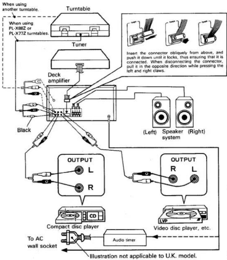
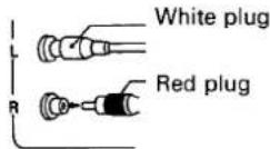
Connecting the input/output cords
- Insert the plugs securely into the jacks. Improper connection can lead to sound distortion or malfunctioning.
● The white plug is for the left channel connection and the red plug for the right channel connection.
Be sure to insert the plugs all the way.
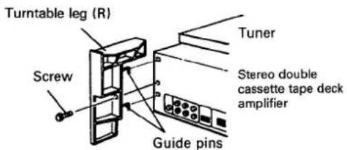
Connecting the speaker cords
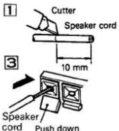
- Check that the speaker cords are secure and will not become disconnected.
NOTE:
Do not allow the conductors of the cords to project beyond the terminals and to come into contact with other conductors. A breakdown or failure may occur when conductors touch one another.
Speaker impedance
Connect speaker systems with a nominal impedance of between 6 and 16 ohms.
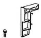
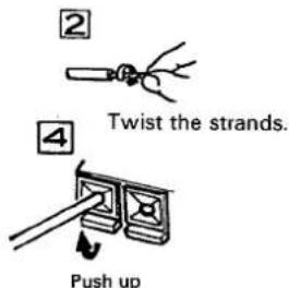
Attaching the legs of the turntable
Attach the legs accompanying the turntable to the rear panel of the cassette deck amplifier.
- Be sure to attach the left (L) and right (R) legs to their proper positions.
- Insert the guide pins on the legs into the holes in the back of the cassette deck amplifier.
-
Fasten the legs in place with the screws provided.
-
After connecting the antenna, mount the turntable securely on top of the legs.
Radio reception is not possible unless the antenna is properly connected.
The strength of broadcast signals varies from one area to another (signal propagation is especially poor in metropolitan areas, where there are many tall buildings, and in mountainous areas). Proper antenna installation is vital to good reception.
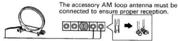
AM ANTENNA
The AM loop antenna supplied with the tuner should be connected to the AM antenna terminals. The antenna should be placed at a distance from the tuner, and should not be allowed to touch metallic objects. Avoid placing it near CD players, personal computers, television sets, and other devices generating radio frequencies.
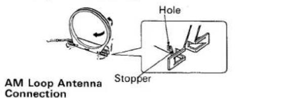
Setting Up the AM Antenna
- Fold out the supports on the bottom of the antenna. Insert the stopper in the hole in the antenna to lock them in place.
- Place the antenna on a level surface and rotate it to locate the orientation that yields the best reception.
AM Loop Antenna Set-up
External AM antenna
Indoor AM antenna
Provide a vinyl-coated wire (5 to 6 meters long). Secure one end to the AM terminal and the other end to a wall or other high location.
External AM antenna
If reception is still poor even when a lead antenna has been stretched out indoors, stretch out a vinyl-coated wire and secure it outdoors.
Connecting the external AM antenna
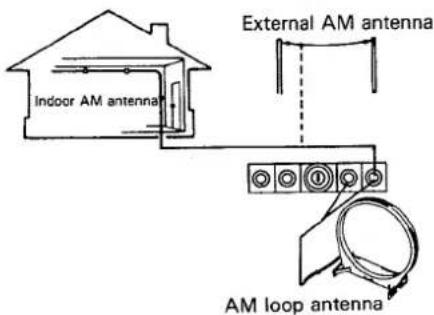
NOTE:
Do not detach the AM loop antenna when using the external AM antenna.
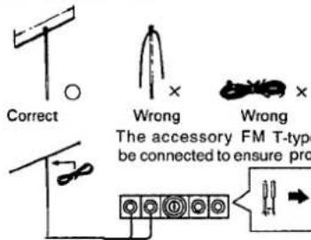
FM ANTENNA
FM T-type Antenna Attachment
Connect the accessory FM T-type antenna to the FM terminals. Stretch the antenna out to its full length, and affix it to a wall, etc.
Stretch out both ends.
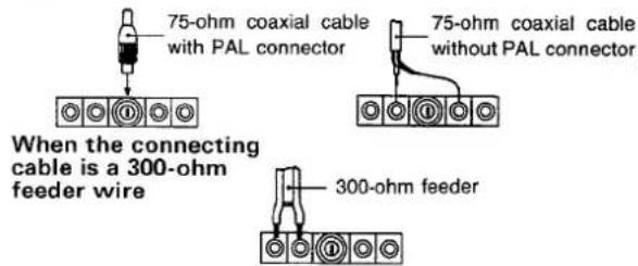
External FM antenna installation
Use an external antenna when the signals from the station are weak and cannot be picked up by the accessory T-type FM antenna, or when the sound heard is accompanied by large amounts of noise. There are two ways of connecting the external FM antenna to the ANTENNA terminals: with 300-ohm feeder wire, or with a 75-ohm coaxial cable. It is recommended that you use the 75-ohm coaxial cable, so that the effects of extraneous noise are reduced to a minimum.
When the connecting cable is a 75-ohm coaxial cable
AM/FM CHANNEL STEP SWITCH (F-X88Z only)
This switch is not provided on models for use in Europe, North America, or Australia. (Provided only on models stamped "Z/E" on packing case.)
The AM/FM channel step switch is located on the rear panel of the digital synthesizer tuner. Before the tuner leaves the factory, this switch is set to the channel allotment plan of the area in which the tuner is sold. When the TUNING switch is given a single push, the frequency display will change in the following units.
| Modeldestination | CHANNEL STEP switch position | Frequency change | |
| FM mode | AM mode | ||
| North America and Continental South America | 100 kHz/10 kHz | 100 kHz | 10 kHz |
| Other countries | 50 KHz/9 kHz | 50 kHz | 9 kHz |
NOTE:
- If the switch is set to the wrong position, correct tuning will not be possible.
Consult your dealer if you are not sure about the channel allotment plan in your area.
5
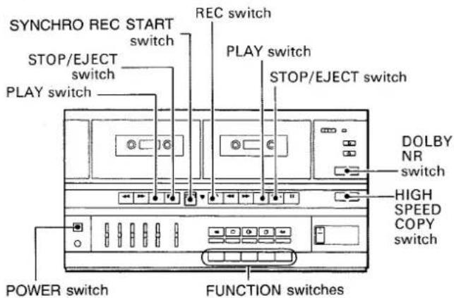
Deck amplifier DC-X77Z
Auto Tape Selector
The purpose of the auto tape selector provided on this unit is to select automatically between normal and CrO_2 tapes when recording and playback. Metal tape position is used for playback only.
Synchronized rec start switch (SYNCHRO REC. START)
Press to start copying from Deck I to Deck II. Set the copying speed (NORMAL or HIGH) using the HIGH SPEED COPY switch.
- Press this switch only after you have set the HIGH SPEED COPY switch as desired.
Dolby NR switch
Set this switch to the ON position to activate the noise reduction system.
- Tapes recorded using Dolby B NR noise reduction should always be played back with the noise reduction system on. Sound quality will be adversely affected if they are played back with the system off, or if tapes recorded using a different noise reduction system are played back with the Dolby B NR system on. - It is recommended that tapes recorded using Dolby B NR be so marked on the label. This will help to prevent incorrect setting of the noise reduction switch during playback.
Noise reduction manufactured under license from Dolby Laboratories Licensing Corporation. "Dolby" and the double-D symbol are trademarks of Dolby Laboratories Licensing Corporation.
POWER switch
When this switch is pressed, power is supplied to the unit. Press the switch again to turn power off.
Headphone jack (PHONES)
For miniature stereo phone plug.
Graphic equalizer controls (GRAPHIC EQUALIZER)
Fine adjustments in sound quality are possible using the 5 controls on the graphic equalizer.
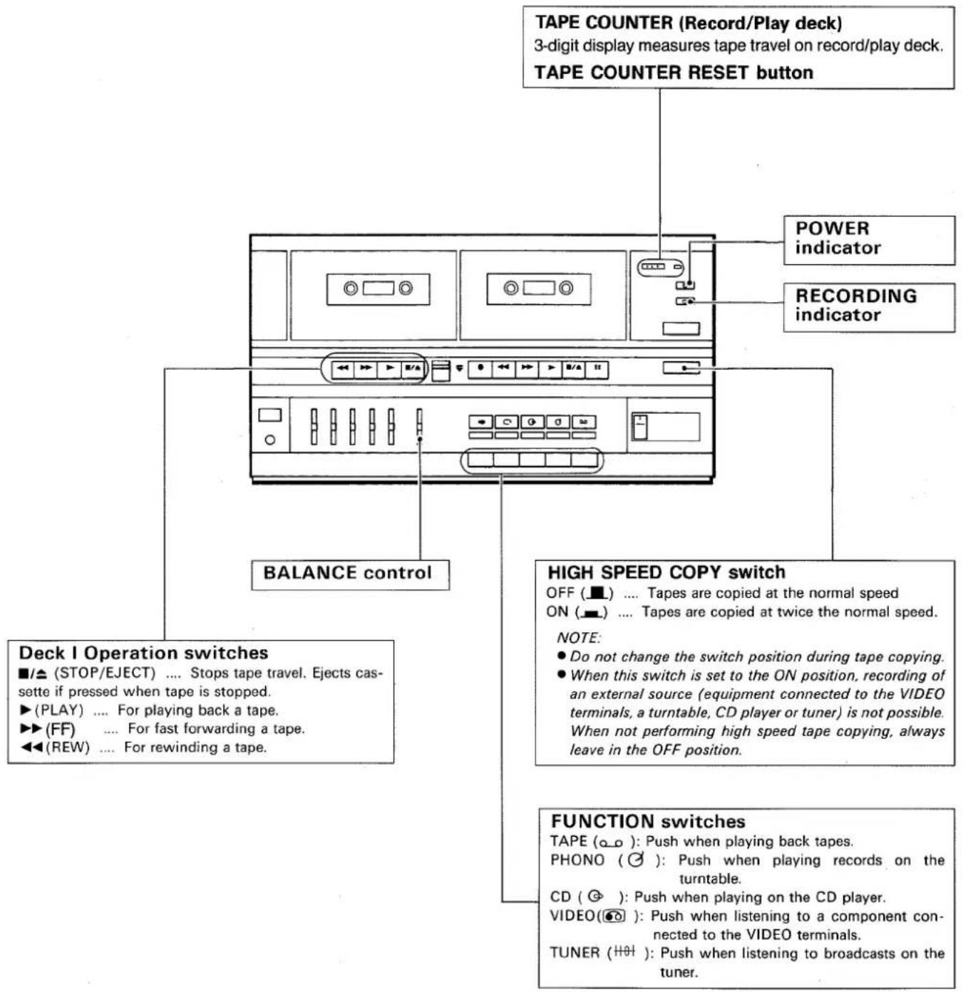
Deck II Operation switches
■ (PAUSE) ... For temporarily stopping the tape run. Cancel pause mode when pressed again.
■/△ (STOP/EJECT) ... Stops tape travel. Ejects cassette if pressed when tape is stopped.
▶ (PLAY) ... For playing back a tape.
▶▶ (FF) ... For fast forwarding a tape.
◀◀ (REW) ... For rewinding a tape.
● (REC) ... For recording material onto a tape.
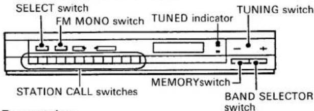
Tuner: F-X88Z/F-X88ZL
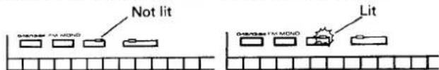
FM MONO switch/indicator
Normally this is set to the off position (the FM MONO indicator goes off). When noise spoils the reception of an FM program, press the switch to the on position (the FM MONO indicator will now light).
The program of an FM stereo broadcast will be heard in mono. The setting of the FM MONO switch (on or off) is memorized along with the station's frequency in the STATION CALL switches.
When using the preset tuning feature, reception will be in the mode selected when the station was memorized.
This switch will not function for AM (MW or LW) reception.
SELECT (1-12/13-24) switch/indicator
This switch is used to set the STATION CALL switches to Mode 1 (1 - 12) or Mode 2 (13 - 24). Mode 2 (13 - 24) is obtained when the switch is pressed and select indicator is lit.
NOTE:
Changing the position of this switch has no effect on tuner performance itself.
FREQUENCY display
Permits reading the received frequency at a glance from the displayed figure. The FM band is indicated by MHz, and the AM (MW or LW) band by kHz.
TUNING switches
These are used to locate the stations. Push either 'of these two switches; the left switch “-” to go to a lower, and the right switch “+” to go to a higher frequency.
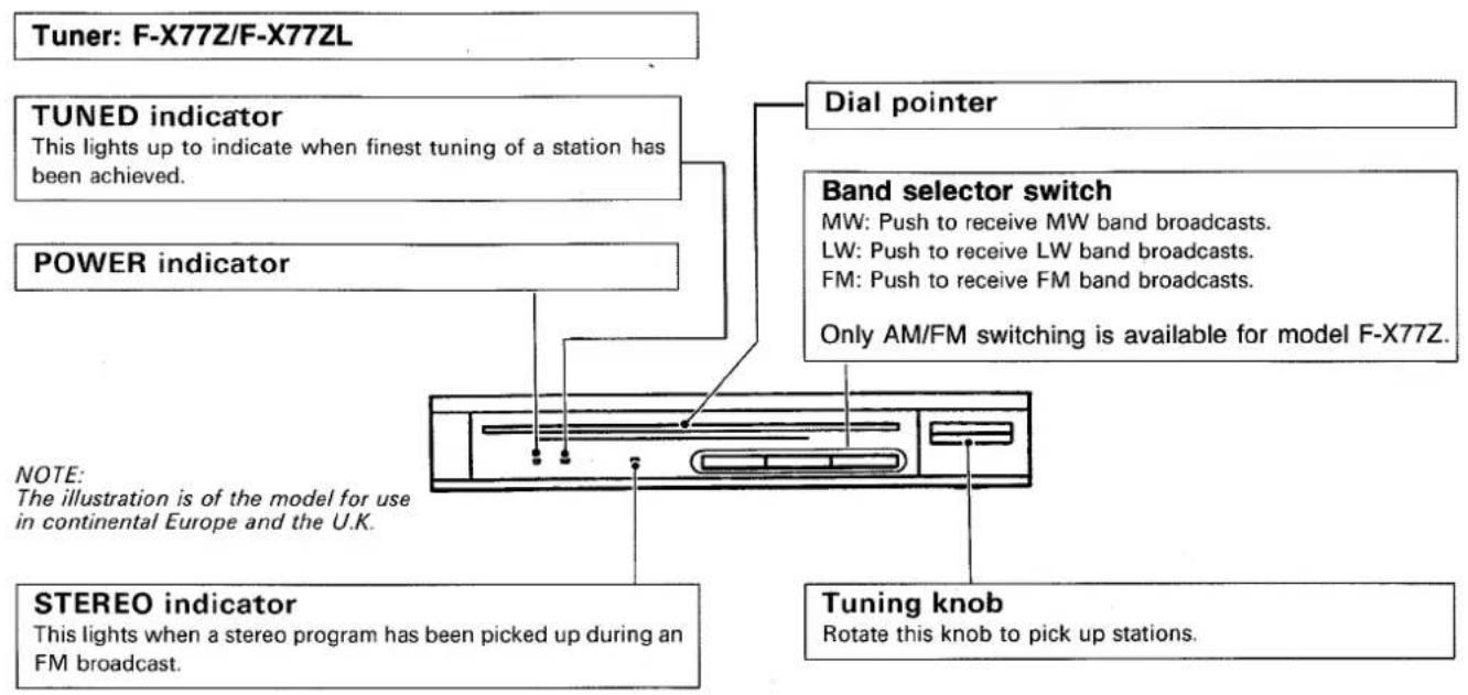
STEREO indicator
This lights when a stereo program has been picked up during an FM broadcast.
TUNED indicator
This lights to indicate when the finest tuning of a station has been achieved.
STATION CALL switch
These are used to recall preset broadcasting stations and to preset the station.
MEMORY switch
This switch is used to memorize stations. When the switch is pressed, the frequency indicator will flash. To memorize the frequency of any station, press the station call switch while the frequency display is flashing.
BAND SELECTOR switch
[For model F-X88Z]
Each time this switch is pressed, FM and AM reception is selected alternately.
FM and MHz light: FM reception
AM and kHz light: AM reception
[For model F-X88ZL]
Each time this switch is pressed, FM, MW and LW reception is selected alternately.
FM and MHz light: FM reception
AM and kHz light: MW or LW reception
![Turntable: PL-X88Z/PL-X77Z NOTE: PL-X77Z is not equipped with Disc size switch. EP adaptor Platter shaft Platter mat Platter Dust cover Arm rest Tonearm Cartridge SPEED switch Set this switch in accordance with the speed of the record. 33: For 33-1/3 rpm records. 45: For 45 rpm records. DISC SIZE switch (only PL-X88Z) Set this switch in accordance with the size of the record. 30: For 30 cm LP records. 17: For 17 cm EP records. START/STOP switch (only PL-X88Z) Press this switch when starting auto play or when stopping play. NOTE: Be sure to press the switch firmly when starting playback; if not pressed firmly, the platter may rotate without the tonearm moving. CUT switch (only PL-X77Z) Press this switch when stopping play. ARM ELEVATION switch • Use the switch for manual play. • Use the switch to suspend record play temporarily. • Use the switch when changing the tracks during actual play. [UP]: The tonearm rises (the stylus moves away from the record). [DOWN]: The tonearm descends (the stylus is lowered onto the record).](/content/2026/05/1047504/images/aac8c4e177ff7e6c04f7414fc88a49729d49811b2493c1035f6da592ec4a4d2c.jpg)
Bear in mind the following points before loading cassette tapes.
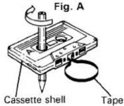
Is the tape loose, or is some of the tape outside the cassette?
If some of the tape is projecting outside the cassette shell or if it is loose, it may not enter between the capstan and pinch roller. This will prevent the tape from being supplied or damage the tape itself. In cases like these, insert a pencil into the reel hole and take up the slack. (Fig. A)
Some cassette tapes come with a plastic or thick paper stopper which prevents tape slack. Remove this stopper when loading the tape and replace it after having used the cassette.
What are the accidental erasure prevention tabs for?
A cassette is provided with these tabs so that important or otherwise valuable recordings will not be erased accidentally. When the tab (Fig. B) on the cassette shell is broken out with the tip of a screwdriver, it will not be possible to activate the recording function even by pressing the recording (REC) switch, so valuable recordings will not be erased in error.
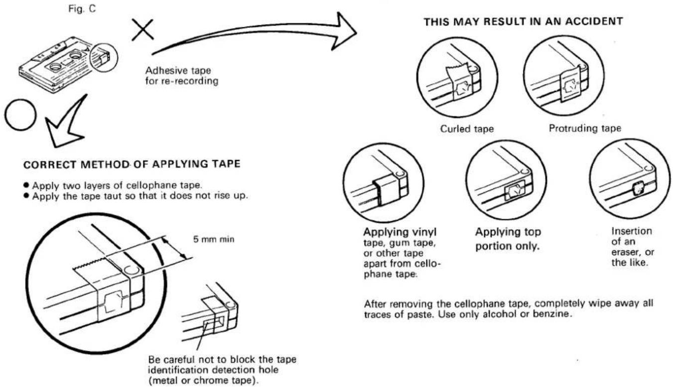
To re-record on a cassette whose tabs have been broken out, simply stick a piece of doubled adhesive tape over the tab areas, as shown in Fig. C.
NOTE:
The accidental erasure prevention tabs are located at the top left on both sides A and B (1 or 2), so that material on each side can be prevented from being erased in error.
Tips on using cassette tapes
- Leader tape (which does not allow sound to be recorded over it) is provided at the beginning of a cassette tape. Start recording after allowing the tape to run for about 5 seconds so that the leader tape clears the recording head.
- Do not leave a cassette tape exposed to the environment. Store the cassette in its case so that dust and dirt do not adhere to the tape after use, and so that the tape is prevented from becoming slack. Choose a location which is not exposed to the effects of magnetism, dust, dirt and oil for storing the tapes.
- Because C-120 tapes are so thin, they easily jam in the pinch roller and capstan, and they are susceptible to other trouble such as irregular winding. Try not to use them with this unit.
How to take up tape slack
How to prevent already recorded tapes from being erased
Fig. B
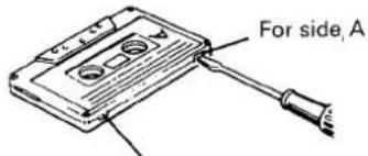
For side B
NOTE FOR RE-RECORDING ON A CASSETTE TAPE WHICH HAS A BROKEN TAB
flowchart
graph TD
    A["Adhesive tape for re-recording"] --> B{Correct Method of Applying Tape}
    B --> C["Apply two layers of cellophane tape.<br>Apply tape taut so that it does not rise up."]
    B --> D["Be careful not to block the tape identification detection hole (metal or chrome tape)."]
    E["This May Result in an Accident"] --> F["Curled tape"]
    E --> G["Protruding tape"]
    H["Applying vinyl tape, gum tape, or other tape apart from cellophane tape."] --> I["Applying top portion only."]
    H --> J["Insertion of an eraser, or the like."]
10
INCORRECT METHOD OF APPLYING TAPE
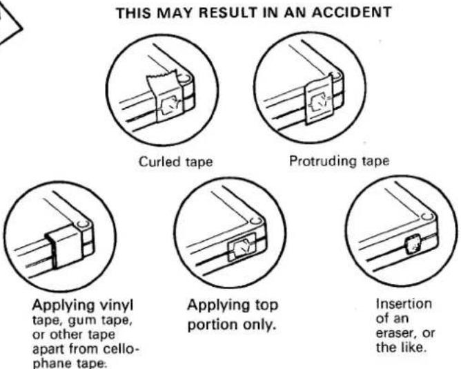
After removing the cellophane tape, completely wipe away all traces of paste. Use only alcohol or benzine.
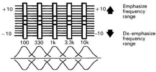
The advantage of the GRAPHIC EQUALIZER over conventional tone controls is that with the five controls of the GRAPHIC EQUALIZER it is possible to control five different narrow. With conventional tone controls a setting for a bass or treble boost or cut will also affect the lower or upper mid frequencies. The frequency bands controlled by the five slide controls have been chosen to yield the maximum possible control action within the audio spectrum.
100 Hz: The 100 Hz control is very useful for enhancing low bass notes as in organ music.
330 Hz: The 330 Hz control will allow you to vary the upper bass frequencies.
1 kHz: The 1 kHz control is the presence control and can be used very effectively to emphasize, or de-emphasize vocalists.
3.3 kHz: The 3.3 kHz control will add brilliance and clarity to brass instruments and violins.
10 kHz: The 10 kHz control can be used to make up for missing high frequencies absorbed by the environment and to add a natural crispness to music.
BASIC OPERATIONS
DECK AMPLIFIER
- Set the cassette tape deck amplifier's POWER switch to on.
- Adjust the volume with the VOLUME control and tone with the GRAPHIC EQUALIZER controls on the cassette tape deck amplifier.
TAPE PLAYBACK
Playback can be performed on either Deck I or Deck II, but if both decks are placed in the playback mode, Deck I will automatically be given priority. If you wish to perform playback on Deck II, be sure that Deck I is in the stop mode.
1 Push the FUNCTION switch in the TAPE position.
2 Load a pre-recorded cassette securely.
3 Select the DOLBY NR switch position.
4 Push the PLAY switch.
5 Push the STOP/EJECT switch to stop the tape playback.
RECORDING (function of Deck II only)
1 Set the FUNCTION switch to the position corresponding to the recording program source (CD, VIDEO, TUNER, or PHONO).
2 Load the cassette tape for recording into Deck II.
3 Select the DOLBY NR switch position.
4 Play a program source.
5 Push REC and PLAY switches at a time.
• The RECORDING indicator will light up.
6 Push the STOP/EJECT switch to stop the recording.
NOTE:
Graphic equalizer effects can be added to the speaker output, but such effects cannot be recorded on the tape.
Auto-Stop Mechanism
When the tape is fully wound onto one reel during recording or playback, the auto-stop mechanism operates to release the tape mechanism and bring the tape to a stop without having to press the STOP/EJECT switch.
This mechanism prevents the tape from becoming stretched and the pinch rollers from being deformed.
Erasing the tape (function of Deck II only)
When recording on a previously recorded tape, the previously recorded sounds will be erased and new recording entered on the tape. To erase a previously recorded tape without recording anew, perform the following operations:
1 Load the cassette tape into Deck II.
2 Set Deck I to the stop mode.
3 Push the FUNCTION switch in the TAPE position.
4 Push the REC and PLAY switches at a time to begin erasing.
RELAY PLAY (from Deck I to Deck II)
Relay play is possible from Deck I to Deck II but not vice versa.
1 Load the pre-recorded cassette tapes to be played back into Deck I and Deck II.
2 Push both of the PLAY switches. Deck I will be set to the playback mode and Deck II to the playback standby mode.
3 When Deck I has finished playing and stops automatically, Deck II will automatically begin playback.
4 When the tape in Deck II has reached its end, the relay play will automatically stop.
TAPE COPYING (from Deck I to Deck II)
Load the playback tape (pre-recorded original tape) into Deck I and the tape for recording into Deck II. When performing tape copying, the copy will have the same characteristics as the tape in Deck I (original tape), regardless of the position of the Dolby NR switch.
Set HIGH SPEED COPY switch to the appropriate position. Then push SYNCHRO REC START switch. Never reverse the order of the steps. Otherwise tape copying may not be performed correctly.
• HIGH SPEED COPY
1 Push the HIGH SPEED COPY switch to ON.
2 Push down the SYNCHRO REC START switch to ON.
3 To stop the tape copying, push both STOP switches.
NOTE:
When performing high speed tape copying, tape copying will take place regardless of the position of the FUNCTION switch. However, sound heard from the speakers will be that of source selected by the FUNCTION switch.
• NORMAL SPEED COPY
1 Release the HIGH SPEED COPY switch to OFF.
2 Push the FUNCTION switch in the TAPE position.
12
3 Push down the SYNCHRO REC START switch to ON.
4 To stop the tape copying, push the both STOP switches.
NOTE:
When performing tape copying at normal speed, be sure to set the FUNCTION switch to the TAPE position. If set to any other position, the signal from that source will be recorded.
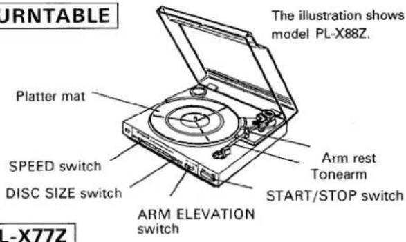
TURNTABLE
RECORD PLAY
1 Press the FUNCTION switch and set it to PHONO.
2 Place the record on the platter mat.
3 Remove the stylus cover and release the tonearm from the arm rest.
4 Set the SPEED switch.
5 Move the arm elevation lever to the UP position.
6 Move the tonearm by hand across the record. At this stage, the platter starts to rotate.
7 Move the arm elevation switch to the DOWN position.
8 To stop the player while a record is being played, press the CUT switch
PL-X88Z
RECORD PLAY (Auto play)
1 Press the FUNCTION switch and set it to PHONO.
2 Place the record on the platter mat.
3 Remove the stylus cover and release the tonearm from the arm rest.
4 Set the SPEED and DISC SIZE (SIZE) switches.
5 Move the arm elevation switch to the DOWN position.
6 Push the START/STOP switch to start record play.
7 To stop the player while a record is being played, press the START/STOP switch.
NOTE:
- When play is completed, the tonearm will return automatically to the arm rest.
- When playing 45 rpm records with large center holes, place the EP adaptor onto the platter shaft.
Beginning Record Playback From Any Point (Manual Play)
1 Press the FUNCTION switch and set it to PHONO.
2 Place the record on the platter mat.
3 Remove the stylus cover and release the tonearm from the arm rest.
4 Set the SPEED switch.
5 Move the arm elevation switch to the UP position.
6 Move the tonearm by hand to the desired position over the record.
7 Move the arm elevation switch to the DOWN position.
- The tonearm will descend onto the record and playback will start.
8 To stop the player while a record is being played, press the START/STOP switch.
TUNER
F-X77Z (L)
The illustration shows model F-X77ZL.
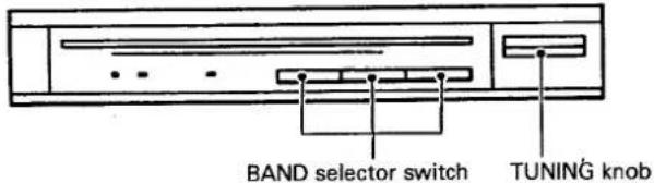
FM AND AM (MW/LW) RECEPTION
1 Press the FUNCTION switch and set it to TUNER.
2 Press the appropriate band selector switch on the stereo tuner.
3 Rotate the TUNING knob and tune in the desired station.
F-X88Z (L)
The illustration shows model F-X88ZL.
Presetting
1 Begin receiving.
- To receive radio station, see "Manual Tunig".
When memorizing an FM station, either press the FM MONO switch to forcibly memorize the station in the monaural mode, or memorize the station in the auto stereo mode (with FM MONO switch left in the OFF position).
2 Press the select switch to select Mode 1 or Mode 2.
When presetting using Mode 1 STATION CALL switches: When presetting using Mode 2 STATION CALL switches:
3 Press the MEMORY switch. During the approximate ten seconds within which the memory circuit functions, push the desired STATION CALL switch to memorize the current frequency in that switch.
- When the flashing of the frequency indicator goes out, presetting is no longer possible. Press the Memory switch again to perform presetting.
4 Repeat steps 1 to 3 to preset station into buttons 1 through 24.
- Up to 24 AM (MW and LW) and FM stations may be preset. If you accidentally preset a station into a STATION CALL switch which contains information, it will be erased and the new station will be entered instead.
Reception using preset tuning
1 Press the STATION CALL switch into which the desired station has been preset. (When necessary, do not neglect to perform Station Mode selection as well.)
Tuning can be performed simply and accurately by following the above procedure.
NOTE:
- The contents of the STATION CALL switch will be preserved for several days, even after the POWER switch is turned off.
- If a preset station has been erased, reset it.
Manual tuning (FM/AM reception)
1 Press the FUNCTION switch and set it to TUNER.
2 Select your desired broadcasting band using the BAND SELECTOR switch.
3 Use the TUNING switch to locate the frequency of your desired station.
For step-by-step searching, press the TUNING switch once and release it immediately. For continuous rapid scanning keep the TUNING switch pressed. The TUNED indicator will light up when the desired station is tuned in best.
NOTE:
The TUNED indicator will not function for broadcasts received over long distances or when signals are weak.
- Connect the power cord of the cassette tape deck amplifier to the audio timer (See page 4) and check that the HIGH SPEED COPY switch is at the OFF position. Operations will vary according to the audio timer used. For details, see the operating instructions supplied with the timer.
UNATTENDED RECORDING (function of Deck II only)
1 Set the POWER switch to ON.
2 Load the tape for recording into Deck II.
3 Push the FUNCTION switch in the TUNER position on the cassette deck amplifier and operate the tuner to tune in the station whose program is to be recorded.
4 Select the DOLBY NR switch.
5 Set the VOLUME control to the minimum position.
6 Set the time on the audio timer so that the power comes on at the desired time (this action switches off the power to the cassette tape deck amplifier).
7 Push the REC switch and PLAY switch at the same time.
8 At the preset time, the power will be switched on and recording will start automatically.
WAKE-UP PLAYBACK (function of Deck I and Deck II)
1 Set the POWER switch to ON.
2 Load a pre-recorded cassette tape.
3 Push the FUNCTION switch in the TAPE position on the cassette tape deck amplifier and adjust the VOLUME control to the appropriate level.
4 Select the DOLBY NR switch.
5 Set the time on the audio timer so that the power comes on at the desired time (this action switches off the power to the cassette tape deck amplifier).
6 Push the PLAY switch of the deck into which the cassette has been loaded.
7 At the preset time, the power will be switched on and the playback will start automatically.
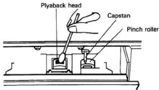
CLEANING THE HEAD SECTION
The head, capstan and pinch roller are parts which are liable to get dirty quite easily. In particular, if the heads are dirty, the high frequency components of the sound will not be reproduced and the stereo balance will be impaired, resulting in a deterioration in sound quality. It is therefore recommended that the head section be cleaned regularly.
- Push the STOP/EJECT switch to open the cassette door.
- Dip a cleaning swab into the cleaning fluid and use it to wipe the heads, capstan, and pinch roller.
DEMAGNETIZING THE HEAD
The rec/playback head becomes magnetized when you use the tape deck for prolonged periods of time. This results in noise being generated and the treble dropping off during recording and playback. The rec/playback head should therefore be demagnetized regularly with a head demagnetizer (sold separately).
For further details, refer to the operating instructions accompanying your head demagnetizer.
NOTE:
- Do not hold screwdrivers, metal objects, or magnets close to the heads.
- When demagnetizing the heads, be sure the unit's POWER switch is in the OFF position.
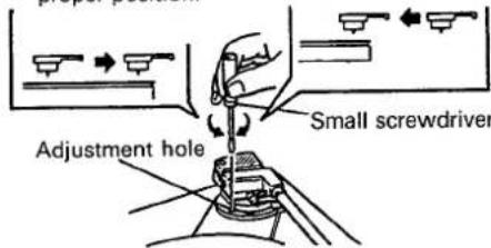
ADJUSTING THE STYLUS DESCENT POSITION
(PL-X88Z only)
Proceed as follows when the stylus does not descend at the proper position on the record during auto play. While performing the adjustment, take care not to scratch the record with the stylus.
1 Place a 30 cm LP record on the platter.
2 Push the START/STOP switch to start auto play.
- Check the direction and amount of stylus deviation (how many millimeters toward the inside or outside of the record's lead-in groove).
3 Push the START/STOP switch to return the tonearm to the arm rest.
4 Set the arm elevation switch to the UP position and manually move the tonearm across the outside edge of the record.
5 Rotate the screw with a small screw-driver in accordance with the direc-
16
tion of the deviation observed in step 2.
- Rotate the screw clockwise if the stylus descends on the outside of the proper position.
- Rotate the screw counterclockwise if the stylus descends on the inside of the proper position.
6 Manually return the tonearm to the arm rest and set the arm elevation switch to the DOWN position.
7 Push the START/STOP switch and check that the stylus stops at the lead-in groove on the outer circumference of the record. If the position is still not correct, repeat steps 2 to 6.
If the stylus descends on the inside of the proper position.
If the stylus descends on the outside of the proper position.
REPLACING THE STYLUS
1 Remove the screw.
2 Pull the cartridge.
3 Remove the stylus gently.
4 Attach the new stylus to the cartridge and replace the screw.
NOTE:
● The service life of the stylus on the supplied cartridge ranges from 800 to 1,000 hours.
- Using a worn or damaged stylus can damage your records and distort the sound reproduction. Remember to replace the stylus at the earliest possible date.
●Always use the PIONEER "PN-295T" as a replacement stylus.
● Always ask for a genuine PIONEER replacement stylus.
TAP is the universal mark for the Plug-in connector system. Products carrying this mark are interchangeable and can be used together.
Remove the screw
Pull the cartridge.
Remove the stylus


PRECAUTION:
If the turntable is mounted directly on or against a speaker, the vibration from the speaker will be transported to the tonearm's cartridge, thus causing feedback howling. Be sure that speakers are mounted sufficiently separated from the turntable.
TROUBLESHOOTING
Incorrect operations are often mistaken for trouble and malfunctions. If you think that there is something wrong with this component, check the points below. Sometimes the trouble may lie in another component. Investigate the other components and electrical appliances being used.
If the trouble cannot be rectified even after exercising the checks listed below, ask your nearest PIONEER authorized service center or your dealer to carry out repair work.
Cassette Deck/Amp
Cassette Deck/Amp
| Symptom | Cause | Remedy |
| No sound from speakers. | • Is volume level turned down? | • Increase volume level. |
| Tape deck will not work. | • Is deck in pause mode?• Is tape loaded correctly? | • Press PAUSE (■■) switch to release pause mode.• Load correctly. |
| No sound from tape deck. | • FUNCTION switch has been set to any position except TAPE.• Is a blank tape loaded?• Are heads clean? | • Set FUNCTION switch to TAPE.• Load a pre-recorded tape.• Clean heads. |
| Recording not possible. | • Is tape loaded in Deck I?• Are heads clean? | • Load blank tape in Deck II for recording.• Clean heads. |
| High frequency sounds not reproduced. | • Are heads clean?• Is a non-Dolby tape being played back with the Dolby NR system on? | • Clean heads.• Turn off the Dolby NR system. |
| High frequencies over-emphasized. | • Is a Dolby NR tape being played back with the Dolby NR system OFF? | • Turn on the Dolby NR system. |
| Noise picked up during recording of tape, record, radio, etc. | • Is power to TV set turned on?• Is unit located too close to TV set? | • Turn off TV set.• Move unit at least 30cm from TV set. |
| Copying not possible | • Is a tab on the cassette tape removed? | • Use a cassette tape with tabs, or place a piece of adhesive tape on the back edge (see page 10). |
Stereo Tuner
| No sound | FUNCTION switch has been set to any position except TUNER. | Set FUNCTION switch to TUNER. |
| AM reception not possible. | Is loop antenna connected?Is band selector switch set to AM?Is station tuned in properly? | Connect loop antenna.Set band selector switch to AM.Tune in station properly. |
| FM reception not possible | Is antenna connected?Is band selector switch set to correct position? | Connect antenna, following instructions on page 5.Set band selector switch to FM. |
| Large amount of noise | Are radio waves weak, causing antenna input to be insufficient? | Switch OFF the CD player. |
Turntable
| Turntable does not work. | • Is drive belt properly attached? | • Attach belt correctly. |
| No sound. | • FUNCTION switch has been set to any position except PHONO. | • Set FUNCTION switch to PHONO. |
| Static, scratching noise produced. | • Is record surface dirty?• Is record warped or scratched? | • Clean record.• Replace record. |
| Stylus does not descend at correct position.(PL-X88Z only) | • Is descend position set correctly?• Is record a special size? | • Adjust descent position as explained on page 16 .• Change record or play back manually. |
Stereo double cassette tape deck amplifier DC-X77Z
AMPLIFIER SECTION
Continuous Power Output
Music power (both channel driven) ...... 50 W + 50 W (1 kHz, T.H.D. 1 %, 8 ohms)
Peak music power 270 W
1 kHz (DIN) 33 W + 33 W (T.H.D. 1% 8 ohms)
1 kHz (DIN music power) .... 50 W + 50 W (T.H.D. 1% 8 ohms)
Graphic equalizer frequency band ..... 100 Hz, 330 Hz, 1 kHz, 3.3 kHz, 10 kHz, ±7 dB
Hum and Noise (IHF, short-circuited, A network) PHONO 72 dB
Hum and Noise (DIN continuous Power/50 mW) PHONO 68 dB/60 dB
Total Harmonic Distortion (40 Hz to 20,000 Hz, 8 ohms) 15 Watts per channel power output ..... No more than 0.2%
Tape Deck Section
Systems 4 track, 2-channel stereo
Heads ...... Recording/playback head x 1
Playback head x 1
Erasing head x 1
Motor DC servo 2 speed motor x 2
Wow and Flutter No more than 0.13% (WRMS)
Fast Winding Time .....Approximately 105 seconds (C-60 tape)
Frequency Response
-20 dB recording: Normal tape .... 35 Hz to 14,000 Hz ± 6 dB CrO _2 .... 35 Hz to 15,000 Hz ± 6 dB
Signal-to-Noise Ratio Dolby NR OFF 56 dB
Noise Reduction Effect Dolby B type NR ON ..... More than 10 dB (at 5 kHz)
Furnished Parts
Operating Instructions 1
Turntable legs parts 2
Miscellaneous
Power requirements
European model AC 220 V, 50/60 Hz
U.K. and Australian models AC 240 V, 50/60 Hz
Other destination models AC 110/120-127/220/240 V (switchable) 50/60 Hz
Power Consumption
European model 210 W
U.K. model 210 W
Other destination models 210 W
Dimensions 360(W) × 190(H) × 283(D) mm
14-3/16(W) × 7-1/2(H) × 11-1/8(D) in
Weight (without package) 6.8 kg (15 lb)
FM/AM tuner: F-X88Z (L)
FM Tuner Section
Frequency range 87.5 MHz to 108 MHz
Usable Sensitivity ..... 12.7 dBf, IHF (1.2 μ V/75 ohms)
50 dB Quieting Sensitivity ... Mono: 18 dBf (2.2 μV/75 ohms) Stereo: 38.3 dBf (22.6 μV/75 ohms)
Sensitivity (DIN) ....Mono : 0.9 μV/75 ohms Stereo : 31.5 μV/75 ohms
Signal-to-Noise Ratio (IHF, 85 dBf Input) .... Mono: 77 dB Stereo: 73 dB
Signal-to-Noise Ratio (DIN) .... Mono: 62 dB Stereo: 60 dB
Distortion Stereo: 0.5% (1 kHz)
Alternate Channel Selectivity 60 dB (400 kHz)
Stereo Separation 40 dB (1 kHz)
Frequency Response .... ±1 dB (30 Hz to 15 kHz)
Image Interference Ratio 38 dB
IF Interference Ratio 110 dB
Antenna Input 300 ohm balanced 75 ohm unbalanced
Output Level (FM 100% MOD) 650 mV
MW (AM) Tuner Section
Frequency range
When 10kHz step 530 kHz to 1,600 kHz
When 9 kHz step 531 kHz to 1,602 kHz
Sensitivity (IHF, Loop antenna) 350 μV/m
Selectivity 20 dB
Signal-to-Noise Ratio 45 dB
Image Interference Ratio 40 dB
IF Interference Ratio 50 dB
Antenna .... Loop Antenna
Output Level (AM 30% MOD) 150 mV
LW Tuner Section
(For LW-equipped models only)
Frequency range 153 kHz to 281 kHz
Sensitivity (IHF, Loop antenna) 1500 μV/m
Selectivity 20 dB
Signal-to-Noise Ratio 45 dB
Image Interference Ratio 30 dB
IF Interference Ratio 50 dB
Antenna Loop Antenna
Output Level (AM 30% MOD) 150 mV
Miscellaneous
Dimensions 360(W) × 56(H) × 215(D) mm
14-3/16(W) ×2-3/16(H) × 8-1/2(D) in
Weight (without package) 1.8 kg (4 lb)
Furnished Parts
FM T-type Antenna 1
AM Loop Antenna 1
FM/AM tuner: F-X77Z (L)
FM Tuner Section
Frequency range 87.5 MHz to 108 MHz
Usable Sensitivity ..... 15.3 dBf, IHF (1.6 μ V/75 ohms)
Sensitivity (DIN) .... Mono: 1.3 μV/75 ohms
Stereo: 35.4 μV/75 ohms
50 dB Quieting Sensitivity ... Mono: 23.3 dBf (4.0 μV/75Ω)
Stereo: 41.2 dBf (31.4 μV/75Ω)
Signal-to-Noise Ratio (IHF, 85 dBf Input) .... Mono: 77 dB
Stereo: 73 dB
Singal-to-Noise Ratio (DIN) .... Mono: 66 dB
Stereo: 60 dB
Distortion ...... Stereo: 0.4% (1 kHz)
Alternate Channel Selectivity 55 dB (400 kHz)
Stereo Separation 40 dB (1 kHz)
Frequency Response Ratio ..... 30 Hz to 15 kHz (±1dB)
Image Interference Ratio 38 dB
IF Interference Ratio 80 dB
AM Suppression Ratio 50 dB
Antenna Input 300 ohm balanced
75 ohm unbalanced
Output Level 650mV (FM 100% MOD)
MW (AM) Tuner Section
Frequency range
U.K., Australian and European models... 531 kHz to 1,602 kHz
Other destination models .... 530 kHz to 1,600 kHz
Sensitivity (IHF, Loop antenna) 250 μV/m
Selectivity 22dB
Signal-to-Noise Ratio 50 dB
Image Interference Ratio 40 dB
IF Interference Ratio 50 dB
Antenna .... Loop Antenna
Output Level 150 mV (AM 30 % MOD)
LW Tuner Section (For LW-equipped models only)
Frequency range 153 kHz to 281 kHz
Sensitivity (IHF, Loop antenna) 890 μV/m
Antenna .... Loop antenna
Output Level 150 mV (AM 30% MOD)
Miscellaneous
Dimensions 360(W) x 56(H) x 217(D) mm
14-3/16(W) × 2-3/16(H) × 8-1/2(D) in
Weight (without package) 1.6 kg (3lb 8 oz)
Furnished Parts
FM T-type Antenna 1
AM Loop Antenna 1
Turntable: PL-X88Z/PL-X77Z
Motor, Platter
Motor Type ...... DC servo motor
Drive Method belt drive
Speed 33-1/3,45 RPM
Speed Variation .... 0.05%WRMS (JIS ± 0.07% WTD
Peak (DIN)
S/N Ratio 68 dB (DIN-B)
Platter 304 mm dia., aluminum die-cast
Tonearm
Type ...... static-balance type, straight tonearm
Installed Cartridge (PC-295T)
Type MM type
Replacement Stylus PN-295T
Stylus 0.6 mil diamond
Output voltage 2.5 mV (1 kHz, 5 cm/s, Lat. peak)
Tracking Force 1—1.5 g (optimum 1.25 g)
Frequency Response 10 Hz to 30,000 Hz
Load Resistance 50 kΩ
Cartridge Weight 6 g
Other
Dimensions 360 W x 96.5 H x 384 D (mm)
Weight
PL-X88Z 3.2 kg (7 lb 1 oz)
PL-X77Z 3.1 kg (6 lb 14 oz)
Accessories
45-RPM Adaptor 1
SYSTEM ACCESSORIES
Operating Instructions 1
Specifications and design subject to possible modifications without notice due to improvement.


natural_image
Completely blank white image with no visible content, text, or symbols.
natural_image
Blank white image with no visible content, text, or symbols.INHALT
Merkmale 22
...... Mono: 23,3 dBf (4,0 μV/75 Ohm)
Stereo: 41,2 dBf (31,4 μV/75 Ohm)
Empfindlichkeit (DIN) .... Mono: 1,3 μV/75 Ohm)
Stereo: 35,4 μV/75 Ohm)
Signal-Rauschabstand (IHF, 85 dBf Eingang) .....
Mono: 77 dB
Stereo: 73 dB
Signal-Rauschabstand (DIN) .... Mono: 66 dB
Stereo: 60 dB
Verzerrung Stereo: 0,4% (1 kHz)
Kanalabstand 55 dB (400 kHz)
Stereokanaltrennung 40 dB (1 kHz)
natural_image
Pure electrical circuit lines without any symbolsnatural_image
Pure technical line drawing of a mechanical component with no text or symbols5 mm min
RECEPTION FM ET AM (PO/GO)
50 W + 50 W (1 kHz, DHT 1%, 8 ohms)
1 kHz (DIN) ..... 33 W + 33 W (DHT 1%, 8 ohms)
1 kHz (puissance musicale DIN) .... 50 W + 50 W
(DHT 1%, 8 ohms)
330 Hz, 1 kHz, 3,3 kHz, 10 kHz, ±7dB
Section platine cassette
Tuner FM/AM: F-X88Z (L)
Section tuner FM
Section tuner PO (AM)
Plage de fréquence
Tuner FM/AM: F-X77Z (L)
Section tuner FM
Mono: 23,3 dBf (4,0 μV/75 ohms)
Section tuner PO (AM)
natural_image
Pure technical line drawing of a mechanical component inside a circle (no text or symbols)5 mm min.
RICEZIONE FM E AM (MW/LW)
50 W + 50 W (1 kHz, THD 1%, 8 ohm)
1 kHz (DIN) ..... 33 W + 33 W (THD 1%, 8 ohm)
1 kHz (potenza musicale DIN) ..... 50 W + 50 W
(THD 1%, 8 ohm)
330 Hz, 1 kHz, 3,3 kHz, 10 kHz, ±7 dB
Mono: 23,3 dBf (4,0 μV/75 ohm)
Stereo: 41,2 dBf (31,4 μV/75 ohm)
- IMPORTANT NOTICE
- LINE VOLTAGE SELECTOR SWITCH
- CONTENTS
- SAFETY INSTRUCTIONS
- IMPORTANT 1
- CAUTION
- RISK OF ELECTRIC SHOCK DO NOT OPEN
- IMPORTANT 2
- FOR USE IN THE UNITED KINGDOM
- FEATURES
- Double deck configuration
- 5-control graphic equalizer
- 24-station random FM/AM presetting (F-X88Z, F-X88ZL)
- FM MONO switch (F-X88Z, F-X88ZL)
- CHECKING THE ACCESSORIES
- INITIAL TURNTABLE SET-UP
- Proceed as follows with the set-up and connections.
- Connecting the input/output cords
- NOTE:
- Speaker impedance
- Attaching the legs of the turntable
- Radio reception is not possible unless the antenna is properly connected.
- AM ANTENNA
- Setting Up the AM Antenna
- External AM antenna
- Indoor AM antenna
- FM ANTENNA
- FM T-type Antenna Attachment
- External FM antenna installation
- AM/FM CHANNEL STEP SWITCH (F-X88Z only)
- Deck amplifier DC-X77Z
- Auto Tape Selector
- Synchronized rec start switch (SYNCHRO REC. START)
- Dolby NR switch
- POWER switch
- Headphone jack (PHONES)
- Graphic equalizer controls (GRAPHIC EQUALIZER)
- Deck II Operation switches
- Tuner: F-X88Z/F-X88ZL
- FM MONO switch/indicator
- SELECT (1-12/13-24) switch/indicator
- FREQUENCY display
- TUNING switches
- STEREO indicator
- TUNED indicator
- STATION CALL switch
- MEMORY switch
- BAND SELECTOR switch
- Bear in mind the following points before loading cassette tapes.
- BASIC OPERATIONS
- TAPE PLAYBACK
- RECORDING (function of Deck II only)
- Auto-Stop Mechanism
- RECORD PLAY
- PL-X88Z
- Beginning Record Playback From Any Point (Manual Play)
- TUNER
- F-X77Z (L)
- FM AND AM (MW/LW) RECEPTION
- F-X88Z (L)
- Presetting
- Begin receiving.
- Press the select switch to select Mode 1 or Mode 2.
- Press the MEMORY switch. During the approximate ten seconds within which the memory circuit functions, push the desired STATION CALL switch to memorize the current frequency in that switch.
- Repeat steps 1 to 3 to preset station into buttons 1 through 24.
- Reception using preset tuning
- Press the STATION CALL switch into which the desired station has been preset. (When necessary, do not neglect to perform Station Mode selection as well.)
- Manual tuning (FM/AM reception)
- UNATTENDED RECORDING (function of Deck II only)
- CLEANING THE HEAD SECTION
- DEMAGNETIZING THE HEAD
- ADJUSTING THE STYLUS DESCENT POSITION
- (PL-X88Z only)
- REPLACING THE STYLUS
- PRECAUTION:
- TROUBLESHOOTING
- Stereo double cassette tape deck amplifier DC-X77Z
- AMPLIFIER SECTION
- Tape Deck Section
- Furnished Parts
- Miscellaneous
- Power Consumption
- FM/AM tuner: F-X88Z (L)
- FM Tuner Section
- MW (AM) Tuner Section
- LW Tuner Section
- (For LW-equipped models only)
- Frequency range
- LW Tuner Section (For LW-equipped models only)
- Motor, Platter
- Tonearm
- Installed Cartridge (PC-295T)
- Other
- Accessories
- SYSTEM ACCESSORIES
- INHALT
- RECEPTION FM ET AM (PO/GO)
- Section platine cassette
- Tuner FM/AM: F-X88Z (L)
- Section tuner FM
- Section tuner PO (AM)
- Tuner FM/AM: F-X77Z (L)
- RICEZIONE FM E AM (MW/LW)
Brand : PIONEER
Model : F-X88ZL
Category : Hi-Fi System