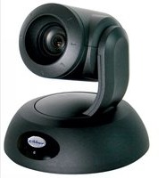
RoboSHOT 30 HDMI - Video Conferencing System Vaddio - Free user manual and instructions
Find the device manual for free RoboSHOT 30 HDMI Vaddio in PDF.


| Product Type | PTZ Video Conferencing Camera |
| Brand | Vaddio |
| Model | RoboSHOT 30 HDMI |
| Optical Zoom | 30x |
| Video Output | HDMI |
| Maximum Resolution | 1920 x 1080 (1080p) |
| Pan Range | +/- 170° |
| Tilt Range | +90° / -30° |
| Dimensions (H x W x D) | 7.2 x 6.8 x 6.8 in (183 x 173 x 173 mm) |
| Weight | 4.4 lb (2.0 kg) |
| Power Supply | 12V DC, 2.5A (PoE+ optional) |
| Mounting | Tabletop, Ceiling (mount included) |
| Control Interfaces | RS-232, IR remote, USB (firmware updates) |
| Supported Protocols | VISCA, Pelco-D, Pelco-P |
| Field of View (Horizontal) | Approx. 2.9° (tele) - 63.7° (wide) |
| Cleaning Instructions | Use a soft dry cloth; avoid liquids or abrasives |
| Safety Precautions | Do not expose to moisture; use only specified power supply |
| Repairability | For professional service; no user-serviceable parts inside |
Frequently Asked Questions - RoboSHOT 30 HDMI Vaddio
User questions about RoboSHOT 30 HDMI Vaddio
0 question about this device. Answer the ones you know or ask your own.
Ask a new question about this device
Download the instructions for your Video Conferencing System in PDF format for free! Find your manual RoboSHOT 30 HDMI - Vaddio and take your electronic device back in hand. On this page are published all the documents necessary for the use of your device. RoboSHOT 30 HDMI by Vaddio.
USER MANUAL RoboSHOT 30 HDMI Vaddio

RoboSHOT 12
High-definition Robotic PTZ Conferencing Camera Featuring a 12X, 73° Wide Angle Optical Zoom Lens and Tri-Synchronous Motion
High-definition Robotic PTZ Camera for Medium to Large Venues
Featuring 30X Optical Zoom Lens and Tri-Synchronous Motion.
Available in Black or White finishes.
RoboSHOT 30
Inside Front Cover - Mostly Blank
Contents
Overview 4
Unpacking the Camera Systems....5
Image: RoboSHOT 12 HD PTZ Camera 6
Image: RoboSHOT 30 HD PTZ Camera 7
Image: RoboSHOT 12 and 30 Rear Panel Connections ....8
System Configuration Examples 9
Diagram: Simple Connectivity Example of the RoboSHOT HDMI Cameras 9
Diagram: Example of the RoboSHOT HDMI Camera in UC Conferencing Application....9
RoboSHOT HDMI Switch Settings 10
Drawing: DIP Switch and Resolution Label on the Bottom of the RoboSHOT 10
Setting the RoboSHOT Switch Gear: 10
DIP Switch Settings Further Explained (DSSFE): 10
Installation Basics: 11
Power Up 11
Controlling the Camera 12
IR Remote Commander 12
Telnet Control Examples 12
The Screen Shot Tour....13
Compatible Web Browsers....13
DHCP IP Set-up (Dynamic Host Configuration Protocol) 13
Static IP Set-up: 13
Screen Shot: Login....13
Screen Shot: Camera Control Page 14
Screen Shot: Storing Presets 15
Screen Shot: Admin login from the Camera Control Page 16
Screen Shot: Admin Menu - Camera Settings....17
Screen Shot: Admin Menu - Room Labels 18
Screen Shot: Admin Menu - DHCP Network Configuration....19
Screen SHOT: Admin Menu - Static IP Configuration 19
Screen SHOT: Admin Menu - Security 20
Screen Shot: Admin Menu - Diagnostics....20
Screen Shot: Admin Menu - System 21
Screen Shot: Admin Menu - Update Confirmation....22
Screen Shot: Admin Menu - Update in Progress....22
Screen Shot - Admin Menu - Help....23
General Specifications 24
Communication Specification 25
Command Setting Values....30
Exposure Control....30
Telnet Serial Command API 31
Telnet Command List 31
camera standby 34
Compliance and CE Declaration of Conformity - RoboSHOT HDMI Cameras 37
Warranty Information 38
OVERVIEW
The RoboSHOT HDMI PTZ cameras are professional quality cameras with very high quality imaging, fine detail and exceptional color reproduction. These cameras offer integrators, dealers and end users a substantial price/performance improvement over and above the value of other HDMI cameras available today.
The RoboSHOT 12 HDMI is perfect for small to medium sized conference rooms, training rooms or classrooms and provides incomparable support for applications including, UC conferencing, videoconferencing, distance learning, lecture capture, telepresence and more!
The optical zoom power of the RoboSHOT 30 HDMI is ideal for medium to large venues and provides exceptional support for applications including, House of Worship services, large auditorium A/V systems, live event theatres, IMAG for performances, large lecture theatres with lecture capture and more!
The key features of the RoboSHOT cameras are Tri-Synchronous Motion, the silent, smooth direct drive pan/tilt motors, advanced Exmor® image sensor, multi-element glass lens and ISP (image signal processor) combination.
The Tri-Synchronous Motion algorithm in the RoboSHOT cameras is capable of moving all three (pan, tilt and zoom) axes simultaneously. The algorithm calculates the position and velocity of the smooth, direct-drive motor movements between the presets so pan, tilt and zoom arrive at the preset subject simultaneously, which finally allows for smooth and manageable on-air camera movements. Yep, there's no more pan/tilt, then zoom like other PTZ cameras available today.

natural_image
Exterior view of a modern office building (no signage)Images:
RoboSHOT 12 HDMI (right) and RoboSHOT 30 HDMI, Black and White Models (below)

natural_image
Two HDMI and Black and White models with adjustable camera heads (no visible text or symbols on devices)The lens, image sensor and ISP are the real magic behind these camera's awesome video performance characteristics. The RoboSHOT 12 HDMI lens features a 12X optical zoom with a 73° wide horizontal field of view and the powerful RoboSHOT 30 HDMI features a 30X optical zoom with an impressive 2.3° tele end and 65° wide field of view. The latest generation Exmor® 1/2.8", 2.38 Megapixel, Full HD (native 1080p/60) high-speed, low noise CMOS image sensor combined with the new ISP produces vivid, realistic color with extremely fast, razor sharp automatic focus and iris routines.
The RoboSHOT HDMI cameras have an Ethernet port and a built-in web server, which allows the user to control the camera functions on a web page with any browser over the IP network. Telnet, IR Remote and RS-232 control for the camera are available to satisfy almost any, if not all, system control requirements.
The RoboSHOT cameras were designed for the times and represent a new era in specifying and integrating professional quality cameras into A/V and conferencing system configurations. In short, it has never been easier to integrate cameras into any project than with the RoboSHOT HDMI cameras

Intended Use:
Before operating the device, please read the entire manual thoroughly. The system was designed, built and tested for use indoors with the power supply provided. The use of a power supply other than the one provided or outdoor operation hasn't been tested and may damage the device and/or create an unsafe operating condition.
Save These Instructions:
The information contained in this manual will help you install and operate your product. If these instructions are misplaced, Vaddio keeps copies of Specifications, Installation and User Guides and most pertinent product drawings (DWG and PDF) for the Vaddio product line on the Vaddio website. These documents can be downloaded from www.vaddio.com free of charge.
Important Safeguards:
Read and understand all instructions before using. Do not operate any device if it has been dropped or damaged. In this case, a Vaddio technician must examine the product before operating. To reduce the risk of electric shock, do not immerse in water or other liquids and avoid extremely humid conditions.

Use only the power supply provided with the system. Use of any unauthorized or extended DC power supplies will void any and all warranties.
UNPACKING THE CAMERA SYSTEMS
Carefully remove the product and all of the included parts from the packaging. Identify the following parts:
RoboSHOT 12 HDMI Camera
Part Number 999-9940-000 (North America)
One (1) RoboSHOT 12 HDMI Camera (998-9940-000)
One (1) Thin Profile Wall Mount with Mounting Hardware
One (1) IR Remote Commander (998-2100-000)
One (1) EZCamera Control Adapter (998-1001-232)
One (1) 12 VDC, 3.0 Amp Switching Power Supply
One (1) AC Cord Set for North America
One (1) Quick Setup Guide
Full Manuals are downloaded from support.vaddio.com
RoboSHOT 12 HDMI Camera
Part Number 999-9940-001 (International)
One (1) RoboSHOT 12 HDMI Camera (998-9940-000)
One (1) Thin Profile Wall Mount with Mounting Hardware
One (1) IR Remote Commander
One (1) EZCamera Control Adapter (998-1001-232)
One (1) 12 VDC, 3.0 Amp Switching Power Supply
One (1) Euro Power Cord
One (1) UK Power Cord
One (1) Quick Setup Guide
Full Manuals are downloaded from support.vaddio.com
RoboSHOT 30 HDMI Camera (Black)
Part Number 999-9943-000 (North America)
One (1) RoboSHOT 30 HDMI Camera (998-9943-000)
One (1) Thin Profile Wall Mount with Mounting Hardware
One (1) IR Remote Commander (998-2100-000)
One (1) EZCamera Control Adapter (998-1001-232)
One (1) 12 VDC, 3.0 Amp Switching Power Supply
One (1) AC Cord Set for North America
One (1) Quick Setup Guide
Full Manuals are downloaded from support.vaddio.com
RoboSHOT 30 HDMI Camera (Black)
Part Number 999-9943-001 (International)
One (1) RoboSHOT 30 HDMI Camera (998-9943-000)
One (1) Thin Profile Wall Mount with Mounting Hardware
One (1) IR Remote Commander
One (1) EZCamera Control Adapter (998-1001-232)
One (1) 12 VDC, 3.0 Amp Switching Power Supply
One (1) Euro Power Cord
One (1) UK Power Cord
One (1) Quick Setup Guide
Full Manuals are downloaded from support.vaddio.com
RoboSHOT 30 HDMI Camera (White)
Part Number 999-9943-000W (North America)
One (1) RoboSHOT 30 HDMI Camera (998-9943-000W)
One (1) Thin Profile Wall Mount (White - not shown) with Hardware
One (1) IR Remote Commander (998-2100-000)
One (1) EZCamera Control Adapter (998-1001-232)
One (1) 12 VDC, 3.0 Amp Switching Power Supply
One (1) AC Cord Set for North America
One (1) Quick Setup Guide
Full Manuals are downloaded from support.vaddio.com
RoboSHOT 12 HDMI Camera (White)
Part Number 999-9943-001W (International)
One (1) RoboSHOT 30 HDMI Camera (998-9943-000W)
One (1) Thin Profile Wall Mount (White - not shown) with Hardware
One (1) IR Remote Commander
One (1) EZCamera Control Adapter (998-1001-232)
One (1) 12 VDC, 3.0 Amp Switching Power Supply
One (1) Euro Power Cord
One (1) UK Power Cord
One (1) Quick Setup Guide
Full Manuals are downloaded from support.vaddio.com

Image: RoboSHOT 12 HD PTZ Camera
Camera Front View with Feature Call-outs

1) Camera and Zoom Lens: This RoboSHOT model features a 12X optical zoom lens (12X in Super-Wide mode and 10X in normal mode) that is built around an Exmor 1/2.8-Type, high-speed, low noise image sensor with a total of 2.38 Megapixels for exceptionally precise HD video image acquisition in a small to medium sized conference room.
2) Camera Support Arm: The RoboSHOT cameras use a single control arm for pan and tilt movements. Both ends of the cast control arm are anchored with silent and smooth BLDC (brushless DC) direct drive motors. These motors provide ultra-accurate and fast camera positioning and are capable of the slowest of crawls, which are suitable for on-air use.
3) IR Sensors: IR sensors are built into the front of the RoboSHOT to receive IR signals from the IR Remote Commander supplied with the camera. The IR sensors sit behind the Makrolon IR Window on the front of the base.
4) Multi-Color LED:
The multi-colored LED indicates the use states of the camera:
- Purple LED is for Boot-up and Standby modes.
- Blue LED is for normal operation and is a power on, ready condition.
• The blue LED will blink when the camera receives a valid IR command.
• Solid red LED is to indicate a tally function illuminating when the camera is on-air. - Blinking red LED indicates a fault condition.
- Yellow LED illuminates during a firmware update.
5) Logo: Really Cool Logo Badge (RCLB) is located on the IR Window.
6) Camera Base: Cast zinc alloy base for strength and stability, powder coated for toughness with fine texture.
Image: RoboSHOT 30 HD PTZ Camera
The differences between the 12X model and the 30X models center around the power of the optical zoom lens and overall color of the camera models. The 30X is available in both black and white.

1) Camera and Zoom Lens: This RoboSHOT model has a powerful 30X optical zoom lens that is built around an Exmor 1/2.8-Typ, high-speed, low noise image sensor with a total of 2.38 megapixels for vibrant, detailed HD video image acquisition in a large to medium sized room.
2) Camera Support Arm: The RoboSHOT cameras use a single control arm for pan and tilt movements. Both ends of the cast control arm are anchored with silent and smooth BLDC (brushless DC) direct drive motors. These motors provide ultra-accurate and fast camera positioning and are capable of the slowest of crawls, which are suitable for on-air use.
3) IR Sensors: IR sensors are built into the front of the RoboSHOT to receive IR signals from the IR Remote Commander supplied with the camera. The IR sensors sit behind the Makrolon IR Window on the front of the base.
4) Multi-Color LED:
The multi-colored LED indicates the use states of the camera:
- Purple LED is for Boot-up and Standby modes.
- Blue LED is for normal operation and is a power on, ready condition.
• The blue LED will blink when the camera receives a valid IR command.
• Solid red LED is to indicate a tally function illuminating when the camera is on-air. - Blinking red LED indicates a fault condition.
- Yellow LED illuminates during a firmware update.
5) Logo: Really Cool Logo Badge (RCLB) is located on the IR Window.
6) Camera Base: Cast zinc alloy base for strength and stability, powder coated for toughness with fine texture.
Image: RoboSHOT 12 and 30 Rear Panel Connections
Rear panel connections are identical for both models (RoboSHOT 12 shown).
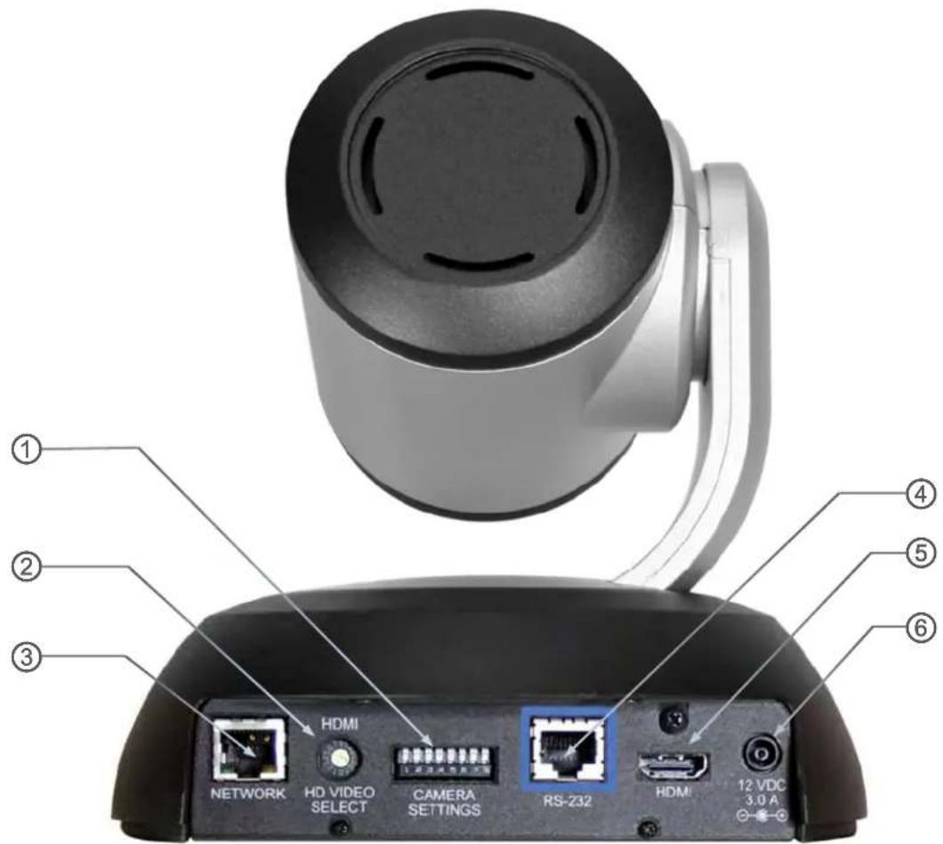
1) CAMERA SETTINGS: DIP switch settings for IR remote frequency, baud rate and image flip can be configured on these switches. See the Switch Settings page for additional information.
2) HD VIDEO SELECT: A rotary switch allows the user to choose the HD video output resolution. See the Switch Settings page for additional information.
3) NETWORK CONTROL Port: The Ethernet 10/100 port allows the camera to be controlled from embedded web server with a web browser or through Telnet session.
4) RS-232 Port (Color Coded Blue): The RS-232 port accepts modified VISCA protocol for camera control over a Cat-5e cable. This port also acts as an IR Forwarding port with the Quick-Connect SR or Quick-Connect DVI/HDMI interfaces, which allows the user to transmit 3^rd party IR signals through camera to the head-end.
5) HDMI Connector: HDMI video output jack (the output Color Space is defaulted to YCbCr for HDMI, but can be switched to sRGB for DVI-D only video devices).
6) Power Jack: The 12 VDC, 3.0 Amp power connector is on an EIAJ-04 jack with a positive center.
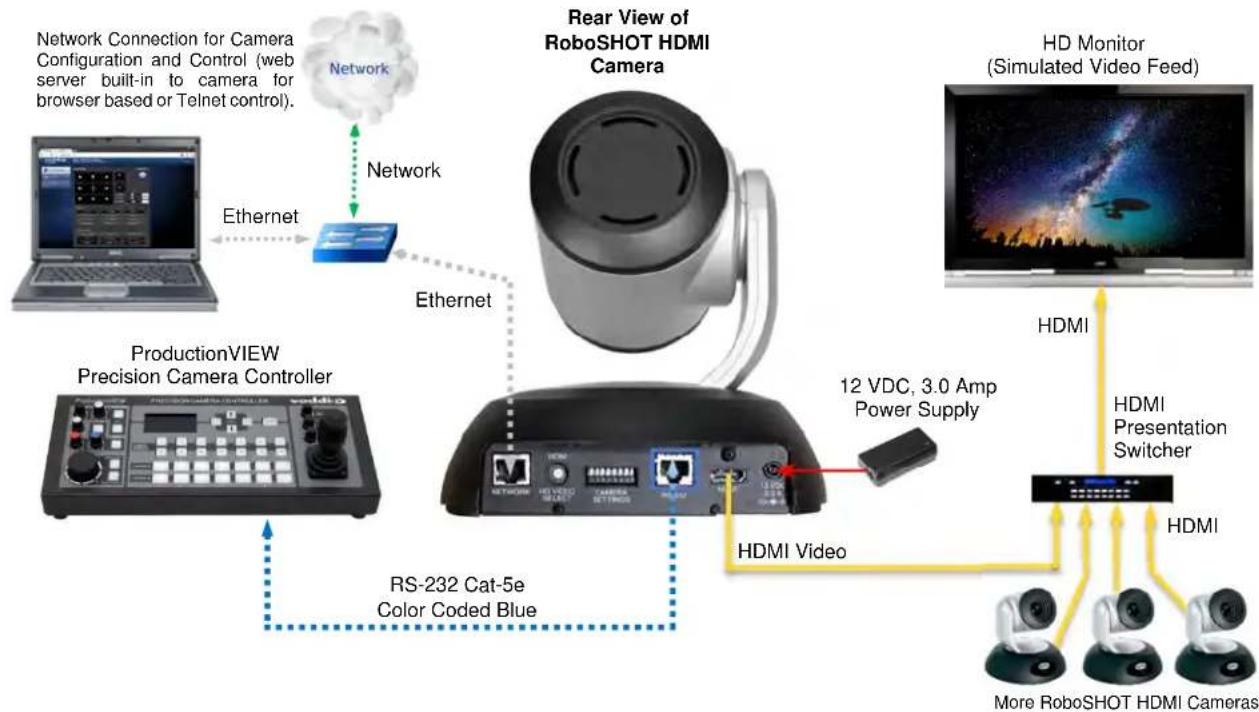
RoboSHOT HDMI camera connected ProductionVIEW™ Precision Camera Controller, Presentation Switcher and HD Monitor.
flowchart
graph TD
    A["Network Connection for Camera Configuration and Control (web server built-in to camera for browser based or Telnet control)."] --> B["ProductionVIEW Precision Camera Controller"]
    B --> C["RS-232 Cat-5e Color Coded Blue"]
    C --> D["12 VDC, 3.0 Amp Power Supply"]
    D --> E["HDMI Video"]
    E --> F["More RoboSHOT HDMI Cameras"]
    G["Rear View of RoboSHOT HDMI Camera"] --> H["Ethernet"]
    H --> I["Network"]
    I --> J["ProductionVIEW Precision Camera Controller"]
    J --> K["RS-232 Cat-5e Color Coded Blue"]
    K --> L["12 VDC, 3.0 Amp Power Supply"]
    L --> M["HDMI Video"]
    M --> N["More RoboSHOT HDMI Cameras"]
    O["HD Monitor (Simulated Video Feed)"] --> P["HDMI Presentation Switcher"]
    P --> Q["HDMI Video"]
    Q --> R["12 VDC, 3.0 Amp Power Supply"]
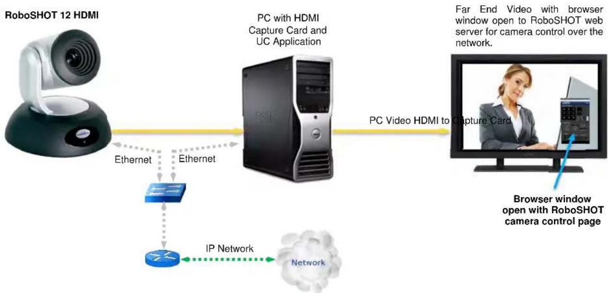
Diagram: Example of the RoboSHOT HDMI Camera in UC Conferencing Application RoboSHOT 12 HDMI camera connected to Room PC with capture card and UC Application.
flowchart
graph LR
    A["RoboSHOT 12 HDMI"] -->|Ethernet| B["PC with HDMI Capture Card and UC Application"]
    B -->|Ethernet| C["IP Network"]
    C --> D["Network"]
    B --> E["PC Video HDMI to Capture Card"]
    E --> F["Browser window open with RoboSHOT camera control page"]
    style A fill:#f9f,stroke:#333
    style B fill:#ccf,stroke:#333
    style C fill:#cfc,stroke:#333
    style D fill:#fcc,stroke:#333
    style E fill:#cff,stroke:#333
    style F fill:#ffc,stroke:#333
RoboSHOT HDMI Switch Settings
The RoboSHOT cameras control the resolution of the video signal. There is, as explained on the page 10, a rotary switch to set the HD video resolution and a set of eight (8) DIP switches that determine certain camera functions. See drawing and Description on how to setup the camera.
Drawing: DIP Switch and Resolution Label on the Bottom of the RoboSHOT

Setting the RoboSHOT Switch Gear:
① - Set the desired available HD output resolution for the camera with the Rotary Switch.
② - Set the IR control frequency of the camera if it is to respond to the IR remote control.
③ - If using the IR forwarding features with a 3^rd party codec IR remote, set the IR OUT switch to ON (SW3).
④ - If inverting the camera, turn the IMAGE FLIP ON (SW4).
⑤ - For the RoboSHOT 12X model only, set the Super-wide mode to ON for a 12X, 73^ horizontal super-wide angle of view. Normal mode will produce 67.2^ horizontal field of view (HFOV). The RoboSHOT 30 does not have a Super Wide mode.
⑥ - Set the Baud Rate DIP switch (SW6) to 9600bps for most applications. Default is 9600 bps systems.
⑦ - Set the color space for HDMI (YCbCr) or for DVI-D (sRGB).
⑧ - Setting all DIP switches DOWN with a power cycle loads the default camera settings. Return DIPs to desired operating position after power cycle
Note: Switch 8 is reserved for future use.
DIP Switch Settings Further Explained (DSSFE):
- IR 1, 2 and 3 (SW 1 &2): A single IR remote has the capability of operating up to three different PTZ cameras in a room. Use these selector DIP switches and the selector buttons at the top of the IR remote to select the frequency.
- IR OUT on/off (SW3): The IR output is sent out on the RS-232 RJ-45 jack on the back of the camera. Turning on the IR output will allow IR signals to be transmitted over the Cat-5 cable to the head end.
• Image Flip (SW4): To invert the camera, turn the IMAGE FLIP ON (switch down). - Super-Wide Mode: Super-wide works only with the RoboSHOT 12 model and allows the camera to switch from 67.3° wide end HFOV to a Super Wide 73° wide end HFOV.
- Baud Rate (SW6): The options for baud rate are either 9600 or 38,400 bps. The 9600 bps works best with Cat-5e over distance. Use 38,400 bps for short control lines only.
• DIP Switches (SW7 & 8): Not used for operation, please leave these DIP switches up or in the OFF position.
INSTALLATION BASICS:
All RoboSHOT cameras include a Thin Profile Wall Mount for...wall mounting the camera. There are options for IN-Wall™ mounts and IN-Ceiling™ Half-Recessed as well.
Pre-Installation
- Choose a camera mounting location while paying close attention to camera viewing angles, lighting conditions, possible line of site obstructions, and checking for in-wall obstructions where the camera is to be mounted. Always pick a mounting location that will optimize the performance of the camera.
- Please locate the camera to enable easy positioning of the camera body with the ability to point down and away from the ceiling and a pile of fluorescent lighting cells. Cameras generally don't like to be swamped with fluorescent light and nobody sits on the ceiling anyway.
- The included RoboSHOT wall mount can be mounted directly to a 2-gang wall box or can be mounted to the wall using the provided dry wall anchors.

RS-232 Cabling Notes:
For RS-232 cabling, use a standard Cat-5 (if you can still find Cat-5) or Cat-5e/6 cable with real RJ-45 connectors crimped on by real crimpers (568B termination) from the camera's RS-232 Port to the controllers RS-232 port. If the camera is connected to a third-party control system (such as AMX or Crestron), a DE-9F (also called a DB-9F in some circles) to RJ-45F control adapter is supplied.
Determine Camera Mount Location and Mount
After determining the optimum location of the camera, route the required cables (HDMI, Power and RS-232) from the camera to the head-end. There are two cable management pass-throughs on the provided mount; one in the back to pass-through into the wall and one in the platform to allow the cabling escape straight down behind a video monitor.
If the wall mount is to be mounted on a 2-gang wall box, use the screws supplied with the wall box cover plate to attach the Thin Profile Wall Mount Bracket. If mounting to drywall with wall anchors, use the four (4) quality wall anchors and screws provided.
The mounting holes are slotted and are 90° opposing to provide easy leveling. Level the mount and place the camera on the mount. Connect the marked and tested Cat-5e cables to the appropriate RJ-45 jacks. Check the level again to avoid any of those weird Batman camera angles. Use the provided 1/4"-20 x .375 mounting screw to attach the Camera to the mount.
Power Up
Connect the supplied 12 VDC, 3.0 Amp power supply to a power outlet
The camera will wake up and initialize (this will take a few seconds since RoboSHOTs use a Linux OS). When an image is available, the camera is ready to accept control information from the IR remote, RS-232, Telnet or embedded web server. We recommend that since there are 4 ways to control the RoboSHOT, pick one and run with it.


CONTROLLING THE CAMERA
IR Remote Commander
The following functions are accessible with the Vaddio IR remote:
- Camera Power On/Off (Toggle on/off same button)
- Back Light Compensation (Toggle on/off same button)
• Data Screen: Toggle on/off the OSD for the RoboSHOT's IP/MAC Address
• Camera Select (the remote can operate 3 cameras (with 3-IR Freq.)
• Pan/Tilt and Home controls with Reverse and Std. Pan direction - Pan/Tilt Reset
• Auto Focus (Toggle on/off same button) -
Zoom In/Out controls Wide & Telephoto
-
Fast speed controls (W & T)
- Slow speed controls (W & T)
- Manual Focus On/Off control (Toggle on/off same button)
- Near (-) adjustment
-
Far (+) adjustment
-
Six (6) pan/tilt/zoom positioning presets (1 through 6)
- Preset Set (store)
- Preset Reset (clear)
- Red LED that indicates IR Transmission and battery level
Vaddio
IR Remote
Commander

The IR Remote operational characteristics are as follows:
- Preset Activation: IR Remote is limited to executing Presets 1 through 6
- Tri-Sync Speed on Preset: If a global Tri-Sync speed is stored in the preset by the user/admin, then that speed is used. If no Tri-Sync speed is assigned, then a default (medium) speed will be used.
- Preset Store: IR Remote is limited to positional (PTZ) type presets. To set a preset, position the camera, hold down the Preset Button and touch the one of the preset numbered buttons 1 through 6.
Telnet Control Examples
The following Telnet* commands are available through the Ethernet Port.
- Camera Home
• Camera Pan (left, right and speed - real-time operation) - Camera Tilt (up, down and speed - real-time operation)
• Camera Zoom (zoom in/out/stop and speed - real-time operation)
• Camera Store Preset (Gets or Sets 16 presets with global relative PTZ [Tri-Sync] speed control to destination) - Camera CCU(Gets or sets current image control values, sets in 1 of 3 CCU presets)
(AWB or manual w/Red and Blue gain, BLC on/off, Auto Iris or manual with Iris value and Gain, Detail and Chroma)
• Camera Standby (Gets or sets standby power mode - camera uses less power in this mode)
• Help (displays CLISH syntax)
• History (command history)
• Network Ping (send ICMP ECHO_REQUEST to network hosts)
• Network Settings (Gets MAC address, IP address, Subnet Mask, Gateway and NTP server address)
• System Factory Reset - System Reboot
• Version (system version information) - Exit (ends Telnet session)

*Please see the full and actual Telnet command list at the end of this manual for the actual command set.
The RoboSHOT camera platform uses a Linux OS and has a built-in web server. The internal web pages will allow control of the attached camera via an Ethernet network connection. These web pages will allow the user or administrator to control the camera, set PTZ presets, set security passwords, change the IP address, view diagnostics, access the firmware upgrade page and more!
Compatible Web Browsers
You may ask, "What are the approved web browsers that work with the RoboSHOT's embedded web server?" The answer is Chrome® (latest version), Firefox® (latest version), Internet Explorer® (versions 8 through 11) and Safari® (versions 6 and 7) have been tested thoroughly with RoboSHOT and are compatible.
DHCP IP Set-up (Dynamic Host Configuration Protocol)
DHCP Set-up (skip this section if Static IP). If the LAN has a DHCP (dynamic host configuration protocol) server, then the IP address, gateway and routing information will automatically be assigned. The software is defaulted to DHCP and will attempt to dynamically obtain an IP address using DHCP, but it will fall back to the default address of (169.254.1.1) if no DHCP server can be found.
Static IP Set-up:
The static IP can be assigned either through the network or directly to a computer using a cross-over cable. Depending on the age of the computer, you may not need a cross-over cable. Either way the steps are the same for network or direct connection to a computer. The default address of the camera is 169.254.1.1 and the Subnet mask is 255.255.0.0. Different computer OS types all have their own way of doing things (without question), but they are essentially doing the same stuff, changing the IP address so the web pages of the RoboSHOT are accessible.
Screen Shot: Login
The RoboSHOT webserver is intended as a user's camera control page at one level, and an administrator's management tool at another level, which requires password authentication for access.
The Login Page will appear if there is a user name assigned by the administrator. Assigning a user name can limit access to the admin menus by a general user.
By default, the User name is: user, and the password for the User account is: password. The Administrator can set the name and password for the User account.
By default, the Admin user name is: admin, and the password for the admin account is: password.

- If a user or an admin logs in through this screen, then the next page shown will be the camera control page.
- The user will only have access to the camera control page.
- The Admin will have complete access to all web pages.
Screen Shot: Camera Control Page
This web page provides access to the camera controls for the User and the Admin.

1) Pan, Tilt and Home Controls: These intuitive controls use the up/down and diagonal arrows for camera pan and tilt. The center button will move the camera to the home position.
2) Zoom Control: The camera's zoom lens can be controlled with the "+" to zoom-in and the "-" to zoom out.
3) Focus Control: Pop up allows the choice of Auto-focus or manual focus with near (+) and far (-) manual focus buttons.
4) Pan/Tilt and Zoom Speed Controls: The speed for both the Pan/Tilt and Zoom controls can be adjusted with the three (3) sliders in this section. For tighter shots, it is recommended that the slower speed is used. These controls are for real-time camera movements only.
5) Standby: The Standby control puts the camera in low power mode and effectively puts the RoboSHOT to sleep. The camera will pan 90° from center and 30° downward (to not collect dust on the lens). When the camera is inverted (ceiling mounted) the camera will pan 90° from center and 30° downward. If the system is on, then the button will be blue and controls will be visible. If the button is red, no controls are accessible and the screen states: Device is in standby. Click to power-up, then you'll know what to do.
6) Camera Presets: Twelve (12) camera position presets can be recalled simply by clicking a preset number.
7) Store Preset Button: Clicking the Store button opens up a Store Preset pop-up dialog box. To set presets, set up the camera shot, click on choice of preset number (1 through 12). The preset is stored and the dialog box closes. The Store Preset dialog bow will prompt the operator to enter the Tri-Sync speed to the stored camera preset and if the current color settings are to be stored with the preset too (see the next page).
8) CCU Scenes: The user has access to the CCU scenes set and stored on the Admin pages. There are three (3) user definable presets and six (6) presets preconfigured by the technical folks at Vaddio (really Scott set them all) that are meant to be used in certain lighting scenarios. These lighting presets included: Automatic, Incandescent Hi, Incandescent Lo, Fluorescent Hi, Fluorescent Lo and Outdoor.
Screen Shot: Storing Presets

1) Store Preset: When the Store Preset button is clicked (point 6 on previous page), the Store Preset dialog pops into existence. To save the current camera shot, click one of the Preset buttons (1 through 12), the button will be highlighted and the dialog box will present the Tri-Sync controls and if the CCU setting are to be kept with the preset.
2) Save with Tri-Sync and Setting the Tri-Sync Speed: The Tri-Synchronous Motion algorithm in the RoboSHOT cameras is capable of moving all three (pan, tilt and zoom) axes simultaneously. The algorithm calculates the PTZ position so pan, tilt and zoom start at the same time and arrive at the preset subject simultaneously. Tri-Sync speed is speed at which all other presets will use to get to the preset being stored. All axes will launch at the same time and if the next preset position is not too close or too far, axes should simultaneously arrive at the preset location. Storing the preset with Tri-Sync is fairly straight forward. Here's a quick method to set Tri-Sync:
a) Position the first preset, click on Store Preset and click on Preset 1. Check the Save with Tri-Sync box. Move the tri-Sync speed slider to about the approximate position above (about 1/3 up the speed scale). This is the speed that all the other presets will use to get to this Preset 1. The speed is stored with the destination preset. Click on Save to store the camera location and Tri-Sync speed.
b) Set another camera position, and try a different pan, tilt and zoom position and click on Store Preset. Click on Preset 2 through 12, click on the Save with Tri-Sync box and set the slider to about 12 way this time and click on Save. These two presets are stored with different preset destination speeds.
c) Click between these two recently stored presets and note the different speeds applied to the 2 presets.

Tri-Sync Notes: If a preset is very close to the previous preset, like within 10^9 with no change in zoom, it certainly doesn't need to be Tri-Sync'd. If a preset is super-fast and off-air, Tri-Sync won't be of much use either. Tri-Sync is a cool tool to set for on-air shots, but the process of setting the speeds will need some practice.
3) Store with Current Color Settings: To save the currently assigned CCU scenes settings, check this box.
4) Click Save or Cancel to exit this pop-up dialog box.
Screen Shot: Admin login from the Camera Control Page
On the security page, which will be reviewed at a bit later in the tour, allows the Admin to set the system to allow automatic guest access to the main camera control page. If guest access is turned on by the Admin, then system will open to the camera control page and an additional Admin Login is provided.
The default Admin password is: password.

Screen Shot: Admin Menu - Camera Settings
Once the Admin logs in, then all the admin menu buttons appear on the left side of the screen. The first menu after Camera Controls is Camera Settings.
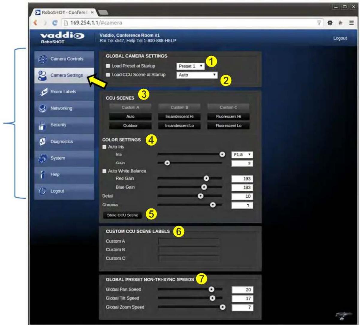
1) Load Preset at Startup: Check this box to move the camera to a predefined preset location when the camera powers up. Use the pull down menu to select the Preset 1 through 12 to be loaded when this box is checked.
2) Load CCU Scene at Startup: Check this box to load a CCU Scene into the camera when the camera powers up. The pull down menu will allow the selection of one of the 6-factory scenes, or one of the 3 custom scenes.
3) CCU Scenes: Click on any of these 9 buttons to load one of the CCU scenes into the camera. These Scenes can be fine-tuned if changes are needed, and stored into any of the three User defined scenes.
4) Color Settings: When painting or shading camera scenes for specific lighting situations or environments, these parameters can be adjusted for matching cameras in the same area. The parameters within the Color Settings section are defined below (top to bottom):
- Auto Iris Check Box: When checked, the camera will operate in Auto Iris mode, when unchecked, the camera will be in Manual Iris mode and allow adjustment of Iris and Iris Gain levels.
-
Iris: Move adjustment slider as required to adjust the iris opening. A numeric value will be displayed in the box to the right of the slider.
-
Gain: Move adjustment slider as required for amount of iris gain desired. Numeric value will be displayed in the box to the right of the slider.
-
Auto White Balance check box: When checked, camera will operate in Auto White Balance mode, when unchecked camera will be in Manual White Balance Mode and allow for adjustment of Red and Blue Gain.
-
Red Gain: Move the adjustment slider as required for amount of Red Gain desired. A numeric value will be displayed in the box to the right of the slider.
-
Blue Gain: Move the adjustment slider as required for amount of Blue Gain desired. Numeric value will be displayed in the box to the right of the slider.
-
Back Light Compensation: When checked, Back Light Compensation will be applied to the camera if camera is in Auto White Balance mode.
- Detail: Move the adjustment slider as required for amount of detail (Aperture) desired. A numeric value will be displayed in the box to the right of the slider. Note: If the detail is too high, the video can look grainy and appear noisy too.
- Chroma: Move the adjustment slider as required for the amount of Chroma (Color Vibrancy) desired. A numeric value will be displayed in the box to the right of the slider.
5) Store CCU Scene button: Once the desired scene adjustments have been made, this button will activate a pop-up menu that can be used to store this scene into one of the three User Defined Scene locations. These User Defined Scenes can be named as required for clarity. These User Defined CCU Scenes can be adjusted and re-saved at any time.

6) Custom CCU Scene Labels: The labels for the (3) User Defined customizable Scenes can be changed as needed. Mouse the cursor into the appropriate window and edit the text. Press Save to store these changes or press Cancel to exit this window.
7) Global Preset Non-Tri-Sync Speeds: When Tri-Sync Presets are not being used, then this section governs the pan, tilt and zoom speeds between the camera presets. These will be defaulted to a nominal level, but can be tailored to most any application.
Screen Shot: Admin Menu - Room Labels
The Room Labels menu allows the Admin to label the company name, room name, room phone and help phone on a per RoboSHOT basis. The labels appear on every page at the top/middle of the page. Simply enter the room information and click Save.

Screen Shot: Admin Menu - DHCP Network Configuration
Under the Networking menu, The Network Configuration and Network Interfaces are displayed. This is where the Network administrator assigns either DHCP or a Static address and the associated parameters.
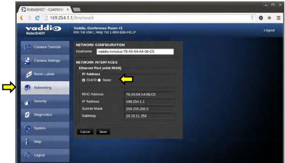
Notes: If the LAN has a DHCP (dynamic host configuration protocol) server, then the IP address, gateway and routing information will automatically be assigned. The software is defaulted to DHCP and will attempt to dynamically obtain an IP address using DHCP, but it will fall back to the default address of (169.254.1.1) if no DHCP server can be found.
Screen SHOT: Admin Menu - Static IP Configuration
If Static IP is used, the IP Address, Subnet Mask and Gateway are manually entered. Click on Save to keep the Static IP information.

Screen SHOT: Admin Menu - Security
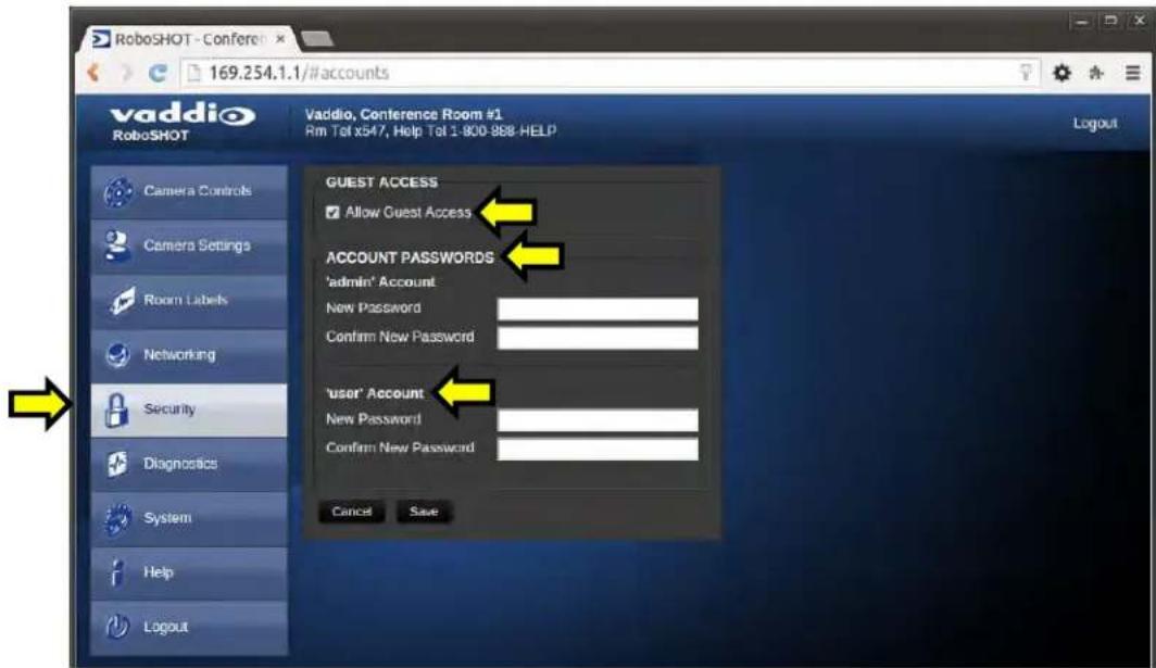
The Security menu allows the Admin to set the Admin and User account names and passwords. There is only one "user" password and only one "admin" password at any given time. If changes are made, click on Save to store the change (it's best to write down the new names and passwords). A Guest Access check box is provided to let any user access the camera control page without logging in. An Admin Login is provided on the camera control page if the "Allow Guest Access" box is checked.
Screen Shot: Admin Menu - Diagnostics
Diagnostics menu button will display a set of self-diagnostics. These diagnostics may help the Vaddio technical support team diagnose a problem with the RoboSHOT camera.
![vaddio RoboSHOT Vaddio, Conference Room #1 Rm Tot x547, Help Tot 1:800:888-HELP CIAGNOSTICS vaddio-romulus-78-A5-04-A4-06-C5 video-service: : pur_setting 0 {"zoom_direct_speed":0} error: 4 {rmessag - vaddio-romulus-78-A5-04-A4-06-C5 video-service: : pur_setting 0 {"zoom_direct_speed":0} error: 4 {rmessag vaddio-romulus-78-A5-04-A4-06-C5 video-service: : pur_setting 0 {"zoom_direct_speed":0} error: 4 {rmessag vaddio-romulus-78-A5-04-A4-06-C5 video-service: : pur_setting 0 {"zoom_direct_speed":0} error: 4 {rmessag vaddio-romulus-78-A5/04-A4-06-C5 video-service: : put_seting 0 {"zoom_direct_speed":0} error: 4 {rmessag vaddio-romulus-78-A5-04-A4-06-C5 camera-service: CameraVisca: _handle_external_command_response: V vaddio-romulus-78-A5-04-A4-06-C5 video-service: : pur_ptz_position 0 {"zoom":{"position":16384}} error: 4 {u} vaddio-romulus-78-A5-04-A4-06-C5 video-service: : 4 put_ptz_position 0 {"zoom":{"position":0}} completion en vaddio-romulus-78-A5-04-A4-06-C5 visca-service: exceptions.KeyError: '22' vaddio-romulus-78-A5-04-A4-06-C5 visca-service: Traceback (most recent call last): vaddio-romulus-78-A5-04-A4-06-C5 File "/usr/lib/python2.7/site-packages/vng_mw_visca/visca_decode.py", lin vaddio-romulus-78-A5-04-A4-06-C5 requested iris = iris_info[user_map][str(requested iris] vaddio-romulus-78-A5-04-A4-06-C5 KeyError: '22' vaddio-romulus-78-A5-04-A4-06-C5 visa-service: : visca_pass_thru 0 [129, 1, 4, 75, 0, 0, 1, 6, 255] error: 4 { vaddio-romulus-78-A5-04-A4-06-C5 visa-service: : exceptions.KeyError: '18' vaddio-romulus-78-A5-04-A4-06-C5 visa-service: Traceback (most recent call last): vaddio-romulus-78-A5-04-A4-06-C5 File "/usr/lib/python2.7/site-packages/vng_mw_visca/visca_decode.py", lin vaddio-romulus-78-A5-04-A4-06-C5 requested iris = iris_info[user_map][str(requested iris] vaddio-romulus-78-A4-A4-06-C5 KeyError: '18' vaddio-romulus-78-A5-04-A4-06-C5 video-service: : visca_pass_thru 0 [129, 1, 4, 75, 0, 0, 1, 2, 255] error: 4 { vaddio-romulus-78-A5-04-A4-06-C5 visa-service: : exceptions.KeyError: '21' vaddio-romulus-78-A5-04-A4-06-C5 visa-service: Traceback (most recent call last): vaddio-romulus-78-A5-04-A4-06-C5 File "/usr/lib/python2.7/site-packages/vng_mw_visca/visca_decode.py", lin vaddio-romulus-78-A5-04-A4-06-C5requested iris = iris_info[user_map][str(requested iris] vaddio-romulus-78-A5-04-A4-06-C5 KeyError: '21' vaddio-romulus-78-A5-04-A4-06-C5 visa-service: : visca_pass_thru 0 [129, 1, 4, 75, 0, 0, 1, 5, 255] error: 4 { vaddio-romulus-78-A5-04-A4-06-C5 visa-service: : exceptions.KeyError: '19' vaddio-romulus-78-A5-04-A4-06-C5 visa-service: Traceback (most recent call last): vaddio-romulus-78-A5-04-A4-06-C5 File "/usr/lib/python2.7/site-packages/vng_mw_visca/visca_decode.py", lin vaddio-romulus-78-A5-04-A4-06-C5Requested iris = iris_info[user_map][str(requested iris] vaddio-romulus-78-A5-04-A4-06-C5 KeyError: '19' vaddio-romulus-78-A5-04-A4-06-C5 visa-service: : visca_pass_thru 0 [129, 1, 4, 75, 0, 0, 1, 3, 255] error: 4 { vaddio-romulus-78-A5-04-A4A-O-C-S C video-service: : visca_pass_thru 0 [129, 1, 4, 75, 0, 0, 1, 3, 255] error: 4 { vaddio-romulus](/content/2026/05/1047264/images/cec1d51974385992fe7f427fd92952c8121157cd736c1d7e9fe4ca49d917612e.jpg)
Screen Shot: Admin Menu - System
The System Menu is where the System Info is displayed and Firmware Updates are performed. There will be firmware updates and upgrades over the life of the camera. The file for the firmware update is chosen in this menu and the update is started here too. A remote system Reboot and Restore to Factory Presets is also available.

1) Firmware Update: The file for the firmware update is chosen in this menu and the update is started here.
2) System Utilities: A remote system Reboot and Restore to Factory Presets is also available.
3) System Information: The System version, Pan & Tilt Motor Versions and Sensor version are displayed in this section.
4) Rear DIP Switch Status: The DIP Switches on the camera are read and displayed for the Admin's reference. This information is read only. These switches determine the IR remote frequency, image flip, and baud rate of the camera and more!
5) Rear Rotary Switch Status: The rotary switch on the back of the RoboSHOT camera determines the video output resolution of the camera. The status is read from the camera (read only) and displayed for the Admin's reference.

Important Note: Anytime a Firmware Update, a System Reboot or a Restore to Factory Settings button is clicked, then a pop-up dialog box will spring up and ask if the intent is to continue or cancel. Please read and understand all the information in the presented in the dialog box prior to proceeding with any unknown procedure.
Screen Shot: Admin Menu - Update Confirmation
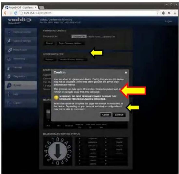
After choosing an update file and clicking on "Begin Firmware Update..." a confirmation pop-up and warning will be displayed. Please contact Vaddio Tech support for assistance with updates. Please read and completely understand the pop-up warnings as it is easy to lose patience waiting for updates. Click on continue to start the update.
Screen Shot: Admin Menu - Update in Progress
After the firmware load has been started, a pop-up screen will advise patience and notify, in terms of percentage completed, the progress of the firmware update load. Again, please don't interrupt the firmware load.

Screen Shot - Admin Menu - Help
Service/Help information can be found under the Help menu. Support phone numbers and e-mail, manuals, FAQ's and System information is listed on support@vaddio.com.

TECHNICAL SUPPORT NOTE:
Please work with your Network Administrator prior to calling Vaddio for technical support. Please have on-site network personnel initiate tech support calls with Vaddio only.
This concludes the RoboSHOT Screen Shot Tour. Please enjoy yourself while reading the rest of this RoboSHOT Camera Manual.
The Next Sections:
The General Specifications, Communication Specifications, API, Telnet Command List, Warranty Information and Declaration of Compliance are breathtaking, stimulating and provocative as one would expect.
GENERAL SPECIFICATIONS

| Function Description | |
| Part Numbers | 999-9940-000: RoboSHOT 12 HDMI, 12X HD Robotic PTZ Camera (North America)999-9940-001: RoboSHOT 12 HDMI, 12X HD Robotic PTZ Camera (International)999-9943-000: RoboSHOT 30 HDMI, 30X HD Robotic PTZ Camera, Black (North America)999-9943-001: RoboSHOT 30 HDMI, 30X HD Robotic PTZ Camera, Black (International)999-9943-000W: RoboSHOT 30 HDMI, 30X HD Robotic PTZ Camera, White (North America)999-9943-001W: RoboSHOT 30 HDMI, 30X HD Robotic PTZ Camera, White (International) |
| Image Device | 1/2.8-Type Exmor CMOS Sensor |
| Video Resolution/Frequencies | 1080p60/59.94/50/30/25, 1080i/60/59.94i/50, 720p/60/59.94/50 |
| Vaddio Special Features | Tri-Synchronous Motion: Concurrent PTZ motor movement and simultaneous PTZ arrival at a stored presetAdvanced ISP: Vivid and accurate color reproduction with extremely fast, razor sharp automatic focus and iris routines |
| Video Aspect Ratio | 16:9 Aspect Ratio for all resolutions |
| Effective Pixels | 2.14 Million Effective pixels2.38 Million Total Pixels |
| RoboSHOT 12Lens and Horizontal FOV | 12X Optical Zoom, Super Wide Mode: 73.0° (wide) to 6.6° (tele),f=3.91mm to 47.0mm, F1.8 to F3.410X Optical Zoom, Normal Mode: 67.3° (wide) to 7.6° (tele), f=3.8mm to 38.0mm, F1.8 to F3.4NOTE: Default is Normal Mode |
| RoboSHOT 30Lens and Horizontal FOV | 30X Optical Zoom65° (wide end) to 2.3° (tele end), F1.6 to F4.7 |
| Minimum illumination RoboSHOT 12 | 1.0 lx (F1.8, 50IRE), recommended illumination >100 lux and <100,000 lux |
| Minimum illumination RoboSHOT 30 | 1.4 lx (F1.6, 50IRE), recommended illumination >100 lux and <100,000 lux |
| Minimum working distance RoboSHOT 12 | 10mm (wide), 800mm (tele) |
| Minimum working distance RoboSHOT 30 | 10mm (wide), 1.2m (tele) |
| S/N ratio | More than 50 dB |
| Sync system | Internal |
| White balance | Auto, ATW, Indoor, Outdoor, One-push, Manual (accessible through external control) |
| Gain | Auto / Manual (0 to 28 steps - accessible through external control) |
| Back-light compensation | On/Off (IR Remote) |
| Focusing system | Auto Focus / Manual Focus Mode / One Push Trigger Mode / Infinity Mode / Near Limit Mode |
| Noise Reduction | On/Off, 6 Steps, Off through 5 (accessible through external control) |
| Aperture/Detail | 16 Steps (accessible through external control) |
| Control Interface(s) | RS-232 API: Modified VISCA Emulation (TTL signal level), Baud rate: 9600 bps and 38,400 bps, 1-Stop bit. Default to 9.6 Kb/s for Cat-5e DistanceTelnet Serial Command AP!Internal Web page for Network Set-up, firmware updates and network managementVaddio IR Remote Commander |
| Pan & Tilt Angle/Speed | Pan/Tilt Angles: ±160°, Tilt: +90°, -30°,Pan/Tilt Speeds: Both Axes 0.35°/sec to 120°/sec |
| Rear Panel Connectors | Network: RJ-45 with Green & Yellow LED to show connection and usageRS-232: RJ-45, Carries bidirectional control to and from the cameraEZ Power Video: RJ-45 Shielded, carries power and differential video signals for the Quick-ConnectCat-5 systems |
| Rear Panel Controls | 16-Position Rotary Switch for Resolution selection8-Position DIP Switch for IR Frequency, Image Flip, wide mode and Reset to Default Settings |
| Power Supply | Powered by Quick-Connect SR Interface |
| Compatible Joystick and Video Control Consoles | ProductionVIEW Precision Camera ControllerAV Bridge MATRIX PRO |
| Operating/Storage Temperature/Humidity | 0°C (32°F) to 40°C (104°F), 20% to 80% |
| Mass | 4.85 lbs.(2.199923 kg - Roughly 900 peanut M&Ms) |
| Dimensions | Small (3 dimensions not counting space/time)6.942" (176.3mm) H x 7.056" (179.2 mm) W x 6.757" (171.6mm) D, |
Notes: Specifications and pricing are subject to change without prior notice or obligation. For dimensional drawings of the products, go to support.vaddio.com and click on drawings.
COMMUNICATION SPECIFICATION
Communication Speed: 9600 bps (default)
Start bit: 1
Stop bit: 1
Data bits: 8
Parity: None
No Flow control

Pin # RJ-45 RS-232 and IR Out Pins
1) Unused
2) Unused
3) Unused
4) IR Output (Diff Signal to Quick-Connect SR)
5) IR Ground (Diff Signal to Quick-Connect SR)
6) GND (GND of IR Short Range - Pin 3)
7) RXD (from TXD of control source)
8) TXD (to RXD of control source)
NOTE: The Vaddio RoboSHOT Control Protocol is similar, but not identical to, the Sony® VISCA™ command set in order to be compatible with several popular control devices. Not all VISCA commands are supported and there are many Vaddio specific commands in the following Command and Inquiry Lists.
RoboSHOT Command List (1/3)
| Command Set | Command | Command Packet | Comments |
| AddressSet Broadcast 88 30 01 FF Address setting | |||
| IF Clear Broadcast 88 01 00 01 FF I/F Clear | |||
| CommandCancel 8x 2p FF | p= Socket No.(1-2) | ||
| CAM_Power | On | 8x 01 04 00 02 FF | Power on |
| Off | 8x 01 04 00 03 FF | Power off | |
| CAM_Zoom | Stop | 8x 01 04 07 00 FF | |
| Tele(std) | 8x 01 04 07 02 FF | ||
| Wide(std) | 8x 01 04 07 03 FF | ||
| Tele(variable) | 8x 01 04 07 2p FF | p= speed 0:low to 7:high | |
| Wide(variable) | 8x 01 04 07 3p FF | p= speed 0:low to 7:high | |
| Direct | 8x 01 04 47 0p 0q 0r 0s FF | pqrs=Zoom Position (0h-4000h) | |
| CAM_DZoom | Not supported | ||
| CAM_Focus | Stop | 8x 01 04 08 00 FF | |
| Far(std) | 8x 01 04 08 02 FF | ||
| Near(std) | 8x 01 04 08 03 FF | ||
| Far(variable) | 8x 01 04 08 2p FF | p= speed 0:low to 7:high | |
| Near(variable) | 8x 01 04 08 3p FF | p= speed 0:low to 7:high | |
| Direct | 8x 01 04 48 0p 0q 0r 0s FF | pqrs=Focus Position (1000h - F000h) | |
| Auto Focus | 8x 01 04 38 02 FF | ||
| Manual Focus | 8x 01 04 38 03 FF | ||
| Auto/Manual | 8x 01 04 08 10 FF | ||
| One Push Trigger | 8x 01 04 18 01 FF | One push AF Trigger | |
| Near Limit | 8x 01 04 28 0p 0q 0r 0s FF | pqrs=Near focus Limit*** | |
| CAM_AFSensitivity | Normal | 8x 01 04 58 02 FF | AF Sensitivity High / Low |
| Low | 8x 01 04 58 03 FF | ||
| CAM_AFMode | Normal AF | 8x 01 04 57 00 FF | AF movement mode |
| Internal AF | 8x 01 04 57 01 FF | ||
| Zoom Trigger AF | 8x 01 04 57 02 FF | ||
| Activate/Internal Time | 8x 01 04 27 0p 0q 0r 0s FF | pqrs=movement time, rs=Interval | |
| CAM_IRCorrection | Standard | 8x 01 04 11 00 FF | Focus IR compensation data switching |
| IR light | 8x 01 04 11 01 FF | ||
| CAM_ZoomFocus | Direct 8x 01 04 47 0p 0q 0r 0s | 0t 0u 0v 0w FF | pqrs=Zoom Position (0h - 7AC0h) |
| tuvw=Focus Position (1000h - F000h) | |||
| CAM_WB | Auto | 8x 01 04 35 00 FF | Normal Auto |
| Indoor | 8x 01 04 35 01 FF | Indoor mode | |
| Outdoor | 8x 01 04 35 02 FF | Outdoor mode | |
| One Push WB | 8x 01 04 35 03 FF | One Push WB mode | |
| ATW | 8x 01 04 35 04 FF | Auto Tracing White Balance | |
| Manual | 8x 01 04 35 05 FF | Manual Control mode | |
| One Push Trigger | 8x 01 04 10 05 FF | One Push WB Trigger | |
| Outdoor Auto | 8x 01 04 35 06 FF | Outdoor auto | |
| Sodium Lamp Auto | 8x 01 04 35 07 FF | Auto including sodium lamp source | |
| Sodium Lamp | 8x 01 04 35 08 FF | Sodium lamp source fixed mode | |
| Sodium Lamp Outdoor Auto | 8x 01 04 35 09 FF | Outdoor auto including sodium lamp source | |
| CAM_RGain | Reset | 8x 01 04 03 00 FF | Manual control of red gain |
| Up | 8x 01 04 03 01 FF | ||
| Down | 8x 01 04 03 02 FF | ||
| Direct | 8x 01 04 43 00 00 0p 0q FF | pq=Red gain (00h - FFh) | |
| CAM_BGain | Reset | 8x 01 04 04 00 FF | Manual control of blue gain |
| Up | 8x 01 04 04 01 FF | ||
| Down | 8x 01 04 04 02 FF | ||
| Direct | 8x 01 04 44 00 00 0p 0q FF | pq=Blue gain (00h - FFh) | |
| CAM_AE | Full Auto | 8x 01 04 39 00 FF | Auto Exposure mode |
| Manual | 8x 01 04 39 03 FF | Manual Control mode | |
| Shutter Priority | 8x 01 04 39 0A FF | Shutter Priority Auto Exposure mode | |
| Iris Priority | 8x 01 04 39 0B FF | Iris Priority Auto Exposure Mode | |
| Bright | 8x 01 04 39 0D FF | Bright Mode (modified AE mode) | |
RoboSHOT Command List (2/3)
| Command Set | Command | Command Packet | Comments |
| CAM Shutter Reset | 8x 01 04 0A 00 FF | Shutter Setting | |
| Up | 8x 01 04 0A 01 FF | ||
| Down | 8x 01 04 0A 02 FF | ||
| Direct | 8x 01 04 4A 00 00 0p 0q FF | pq=Shutter Position (00h - 15h) | |
| CAM_Iris | Reset | 8x 01 04 0B 00 FF | Iris Setting |
| Up | 8x 01 04 0B 01 FF | pq=Iris Position** | |
| Down | 8x 01 04 0B 02 FF | RoboSHOT 12 (0h, 07h-11h) | |
| Direct | 8x 01 04 4B 00 00 0p 0q FF | RoboSHOT 30 (0h, 05h-11h) | |
| CAM_Gain | Reset | 8x 01 04 0C 00 FF | Iris Gain Setting |
| Up | 8x 01 04 0C 01 FF | ||
| Down | 8x 01 04 0C 02 FF | ||
| Direct | 8x 01 04 4C 00 00 0p 0q FF | pq=Gain Position (01h - 0Fh) | |
| +Gain Limit | 8x 01 04 2C 0p FF | p= Gain limit (04h-0Fh) | |
| CAM_ExpComp | On | 8x 01 04 3E 02 FF | Exposure Compensation On |
| Off | 8x 01 04 3E 03 FF | Exposure Compensation Off | |
| Reset | 8x 01 04 3E 00 FF | ||
| Up | 8x 01 04 3E 01 FF | ||
| Down | 8x 01 04 3E 02 FF | ||
| Direct | 8x 01 04 4E 00 00 0p 0q FF | pq=ExpComp Position(0h-0Eh) | |
| CAM_BackLight | On | 8x 01 04 33 02 FF | Backlight Compensation On/Off |
| Off | 8x 01 04 33 03 FF | ||
| CAM_Tally | On | 8x 01 7E 01 0A 00 02 FF | |
| Off | 8x 01 7E 01 0A 00 03 FF | ||
| CAM_SpotAE | On | 8x 01 04 59 02 FF | Spot Auto Exposure Setting |
| Off | 8x 01 04 59 03 FF | ||
| Position | 8x 01 04 29 0p 0q 0r 0s FF | pq=X-(0h-0fh), rs=Y-(0h-0fh) | |
| CAM_WD | On | 8x 01 04 3D 02 FF | WD On |
| Off | 8x 01 04 3D 03 FF | WD Off | |
| VE On | 8x 01 04 3D 06 FF | VE On | |
| Set Parameter | 8x 01 04 2D 00 0q 0r 0s | p=Display brightness level (0Dark - 6Bright) | |
| 00 00 00 00 FF | r=Brightness compensation selection (0:Very dark,1:Dark,2:std,3:bright) | ||
| s=Compensation level (0:Low,1:Mid,2:High) | |||
| CAM_Aperture | Reset | 8x 01 04 02 00 FF | Aperture Setting |
| Up | 8x 01 04 02 01 FF | ||
| Down | 8x 01 04 02 02 FF | ||
| Direct | 8x 01 04 42 00 00 0p 0q FF | pq=Aperture Position (0h-ffh) | |
| CAM_HR | On | 8x 01 04 52 02 FF | High Resolution Mode On/Off |
| Off | 8x 01 04 52 03 FF | ||
| CAM_NR -- 8x 01 04 53 0p FF p= Noise Reduction level(0:Off,1-5) | |||
| CAM_Gamma -- 8x 01 04 5B 0p FF p= Gamma setting(0:std,1:Straight) | |||
| CAM_LR_Reverse | On | 8x 01 04 61 02 FF | LR Reverse On/Off (mirror) |
| Off | 8x 01 04 61 03 FF | ||
| CAM_Freeze | On | 8x 01 04 62 02 FF | Freeze On/Off |
| Off | 8x 01 04 62 03 FF | ||
| CAM_PictureEffect | Off | 8x 01 04 63 00 FF | Picture Effect Setting |
| Neg.Art | 8x 01 04 63 02 FF | ||
| Black & White | 8x 01 04 63 04 FF | ||
| CAM_PictureFlip | On | 8x 01 04 66 02 FF | Image-Flip On/Off |
| Off | 8x 01 04 66 03 FF | ||
| CAM_ICR | On | 8x 01 04 01 02 FF | ICR Mode On/Off |
| Off | 8x 01 04 01 03 FF | ||
| CAM_IDWrite | 8x 01 04 22 0p 0q 0r 0s FF | pqrs=Camer ID (0h-ffffh) | |
| CAM_Memory | Reset | 8x 01 04 3F 00 0p FF | p= preset number(0h-0fh) |
| Set standard | 8x 01 04 3F 01 0p FF | qr= Speed(01h-18h) | |
| Set standard with 'scene' | 8x 01 04 3F 21 0p FF | ||
| Set Tri-sync | 8x 01 04 3F 11 0p 0q 0r FF | ||
| Set Tri-Sync with 'scene' | 8x 01 04 3F 31 0p 0q 0r FF | ||
| Recall standard | 8x 01 04 3F 02 0p FF | ||
| Recall Tri-sync | 8x 01 04 3F 12 0p FF | ||
RoboSHOT Command List (3/3)
| Command Set | Command | Command Packet | Comments |
| Cam_Display | On | 8x 01 04 15 02 FF | Display On/Off |
| On(alternate) | 8x 01 06 06 02 FF | ||
| Off | 8x 01 04 15 03 FF | ||
| Off(alternate) | 8x 01 06 06 03 FF | ||
| On/Off | 8x 01 04 15 10 FF | ||
| On/Off(alternate) | 8x 01 06 06 10 FF | ||
| Cam_Mute | On | 8x 01 04 75 02 FF | Mute On/Off |
| Off | 8x 01 04 75 03 FF | ||
| On/Off | 8x 01 04 75 10 FF | ||
| CAM_ColorEnhance | Parameter Set | 8x 01 04 20 mm 00 pp | mm: Threshold levelpp: Y fixed color for high-intensityqq: Cr fixed color for high-intensityrr: Cb fixed color for high-intensityss: Y fixed color for low-intensitytt: Cr fixed color for low-intensityuu: Cb fixed color for low-intensityEach parameter setting 00h to 7FhColor Enhancement On/Off |
| On | 8x 01 04 50 02 FF | ||
| Off | 8x 01 04 50 03 FF | ||
| CAM_ChromaSuppress 8x 01 04 5F pp FF pp: Chroma Suppress setting level | 00: Off01h to 03h: On (3 levels).Effect increases as the level numberincreases. | ||
| CAM_ColorGain Direct 8x 01 04 49 | 00 00 00 0p FF p: Color Gain Setting 0h to 4h | ||
| CAM_ColorHue | Direct | 8x 01 04 4F 00 00 00 0p FF | p: Color Hue Setting 0h (-14 degrees) to Eh (+14 degrees) |
| CAM_GammaOffset | Direct | 8x 01 04 1E 00 00 00 0s 0t 0u FF | s: Polarity offset (0 is plus, 1 is minus)tu: Offset s=0 (00h to 40h)Offset s=1 (00h to 10h) |
| Pan-TiltDrive | Up | 8x 01 06 01 vv ww 03 01 FF | vv= Pan speed (01h-18h)ww=Tilt speed (01h-14h) |
| Down | 8x 01 06 01 vv ww 03 02 FF | ||
| Left | 8x 01 06 01 vv ww 01 03 FF | ||
| Right | 8x 01 06 01 vv ww 02 03 FF | ||
| UpLeft | 8x 01 06 01 vv ww 01 01 FF | ||
| UpRight | 8x 01 06 01 vv ww 02 01 FF | ||
| DownLeft | 8x 01 06 01 vv ww 01 02 FF | ||
| DownRight | 8x 01 06 01 vv ww 02 02 FF | ||
| Stop | 8x 01 06 01 vv ww 03 03 FF | ||
| Absolute Position 8x 01 06 02 | vv ww 0Y 0Y 0Y 0Y0Z 0Z 0Z 0Z FF | vv= Pan speed (01h-18h)ww=Tilt speed (01h-14h)0Y0Y0Y0Y = Pan position(90E2h-6BD8h)0Z0Z0Z0Z = Tilt position(EB99h-3D59h) | |
| Home | 8x 01 06 04 FF | ||
| Pan-Tilt-ZoomDrive | Up | 8x 01 06 0A vv ww rr 03 01 03 FF | vv= Pan speed (01h-18h)ww=Tilt speed (01h-14h)rr=Zoom speed (00h-07h) |
| Down | 8x 01 06 0A vv ww rr 03 02 03 FF | ||
| Left | 8x 01 06 0A vv ww rr 01 03 03 FF | ||
| Right | 8x 01 06 0A vv ww rr 02 03 03 FF | ||
| In | 8x 01 06 0A vv ww rr 03 03 01 FF | ||
| Out | 8x 01 06 0A vv ww rr 03 03 02 FF | ||
| Stop | 8x 01 06 0A vv ww rr 03 03 03 FF | ||
| Absolute Position | 8x 01 06 0B vv ww 0Y 0Y 0Y 0Y0Z 0Z 0Z 0R 0R 0R 0R FF | vv: Pan speed (01h-18h)ww: Tilt speed (01h-14h)0Y0Y0Y0Y = Pan position(90E2h-6BD8h)0Z0Z0Z0Z = Tilt position(EB99h-3D59h)0R0R0R0R = Zoom position(0000h-7AC0h) | |
| Home | 8x 01 06 0C FF | ||
| CAM_PTZ_PresetSpeed | 8x 01 7e 01 0b pp qq rr FF | pp:pan speed (01h-18h),qq:tilt speed (01h-14h),rr:zoom speed (0h-07h) | |
RoboSHOT Inquiry List (1/2)
| Inquiry Command | Command | Response Packet | Comments |
| CAM_PowerInq 8x 09 04 00 FF | y0 50 02 FFY0 50 03 FF | OnOff (Standby) | |
| CAM_ZoomPosInq 8x 09 04 47 FF | y0 50 0p 0q 0r 0s FF pqrs: | Zoom Position | |
| CAM_FocusModelInq 8x 09 04 38 | FF y0 50 02 FF | y0 50 03 FF | Auto FocusManual Focus |
| CAM_FocusPosInq 8x 09 04 48 FF | y0 50 0p 0q 0r 0s FF pqrs: | Focus Position | |
| CAM_FocusNearLimitInq 8x 09 04 28 FF y0 50 0p 0q 0r 0s FF | pqrs: Focus Near Limit Position | ||
| CAM_AFSensitivityInq | 8x 09 04 58 FF y0 50 02 FF | y0 50 03 FF | AF Sensitivity NormalAF Sensitivity Low |
| CAM_AFModelInq | 8x 09 04 57 FF y0 50 00 FF | y0 50 01 FFY0 50 02 FF | Normal AFInterval AFZoom Trigger AF |
| CAM_AFTimeSettingInq | 8x 09 04 27 FF y0 50 0p 0q | Or 0s FF pq: Movement Time, rs: Interval | |
| CAM_IRCorrectionInq | 8x 09 04 11 FF y0 50 00 FF | y0 50 01 FF | StandardIR Light |
| CAM_WBModelInq | 8x 09 04 35 FF y0 50 00 FF | y0 50 01 FFY0 50 02 FFY0 50 03 FFY0 50 04 FFY0 50 05 FFY0 50 06 FFY0 50 07 FFY0 50 08 FFY0 50 09 FF | AutoIndoorOutdoorOne Push WBATWManualOutdoor AutoSodium Lamp AutoSodium LampSodium Lamp Outdoor Auto |
| CAM_RGainInq 8x 09 04 43 FF y0 50 00 00 0p 0q FF | pq: R Gain | ||
| CAM_BGainInq | 8x 09 04 44 FF y0 50 00 00 | 0p 0q FF | pq: B Gain |
| CAM_AEModelInq | 8x 09 04 39 FF y0 50 00 FF | y0 50 03 FFY0 50 0A FFY0 50 0B FFY0 50 0D FF | Full AutoManualShutter PriorityIris PriorityBright |
| CAM_ShutterPosInq | 8x 09 04 4A FF | y0 50 00 00 0p 0q FF | pq: Shutter Position |
| CAM_IrisPosInq | 8x 09 04 4B FF | y0 50 00 00 0p 0q FF | pq: Iris Position |
| CAM_GainPosInq | 8x 09 04 4C FF | y0 50 00 00 0p 0q FF | pq: Gain Position |
| CAM_GainLimitInq | 8x 09 04 2C FF | y0 50 0q FF | p: Gain Limit |
| CAM_ExpCompModelInq | 8x 09 04 3E FF | y0 50 02 FFY0 50 03 FF | OnOff |
| CAM_ExpCompPosInq | 8x 09 04 4E FF | y0 50 00 00 0p 0q FF | pq: ExpComp Position |
| CAM_BackLightModelInq | 8x 09 04 33 FF y0 50 02 FF | y0 50 03 FF | OnOff |
| CAM_TallyInq | 8x 09 7E 01 0A FF | y0 50 02 FFY0 50 03 FF | OnOff |
| CAM_ResolutionInq | 8x 09 06 23 FF | y0 50 0p 0q FF | Pq=Video Resolution |
| CAM_SpotAEModelInq | 8x 09 04 59 FF y0 50 02 FF | y0 50 03 FF | OnOff |
| CAM_SpotAEPosInq | 8x 09 04 29 FF | y0 50 0p 0q 0r 0s FF | pq: X Position, rs: Y Position |
| CAM_WDModelInq | 8x 09 04 3D FF | y0 50 02 FFY0 50 03 FFY0 50 06 FF | OnOffVE On |
| CAM_WDParameterInq | 8x 09 04 2D FF | y0 50 00 0q 0r 0s 0t 0u 00 00 FF | q: Display brightness level (0: Dark to 6: Bright)r: Brightness compensation selection (0: Very dark,1: Dark, 2: Standard, 3: Bright)s: Compensation level (00h: Low,01h: Mid, 02h: High)tu: Always 0 |
| CAM_ApertureInq | 8x 09 04 42 FF | y0 50 00 00 0p 0q FF | pq: Aperture Gain |
| CAM_HRModelInq | 8x 09 04 52 FF y0 50 02 FF | y0 50 03 FF | OnOff |
| CAM_NRInq | 8x 09 04 53 FF | y0 50 0p FF | Noise Reduction p: 00h to 05h |
| CAM_GammalInq 8x 09 04 5B FF | y0 50 0p FF | Gamma p: 00h | 01h |
RoboSHOT Inquiry List (2/2)
| Inquiry Command | Command | Response Packet | Comments |
| CAM_LR_ReverseModelnq 8x 09 | 04 61 FF y0 50 02 FF | y0 50 03 FF | On (mirror)Off |
| CAM_FreezeModelnq 8x 09 04 62 | FF y0 50 02 FF | y0 50 03 FF | OnOff |
| CAM_PictureEffectModelnq 8x 09 | 04 63 FF y0 50 00 FF | y0 50 02 FFy0 50 04 FF | OffNeg. ArtBlack & White |
| CAM_PictureFlipModelnq 8x 09 04 | 66 FF y0 50 02 FF | y0 50 03 FF | OnOff |
| CAM_ICRModelnq 8x 09 04 01 FF | y0 50 02 FF | y0 50 03 FF | OnOff |
| CAM_MemoryInq 8x 09 04 3F FF | y0 50 pp FF pp: Memory num | ber recalled last | |
| CAM_MemoryStatusInq | 8x 09 04 3F 0p FF | y0 50 0p 0q 0r 0s FF | p: Memory numberq: mode (00-std, 10-std /w ccu,01-trisync,11-trisyc /wccu)rs: speed (0x1-0x18) 1 - 24 |
| CAM_MemSavelnq | 8x 09 04 23 0X FF | y0 50 0p 0q 0r 0s FF | X: 00h to 07h (Address)pqr: 0000h to FFFFh (Data) |
| CAM_DisplayModelnq | 8x 09 04 15 FF(8x 09 06 06 FF) | y0 50 02 FFy0 50 03 FF | OnOff |
| CAM_MuteModelnq | 8x 09 04 75 FF y0 50 02 FF | y0 50 03 FF | OnOff |
| CAM_IDInq | 8x 09 04 22 FF y0 50 0p 0q | Dr 0s FF pqr: Camera ID | |
| CAM_VersionInq | 8x 09 00 02 FF y0 50 00 10 | mn pq 0E 0E 02 FF | mnpq: Model Code |
| Vaddio_ModelInq | 8x 09 08 0e FF | y0 50 05 00 00 00 00 FFy0 50 05 01 00 00 00 FF | RoboSHOT-12RoboSHOT-30 |
| CAM_RegisterValueInq | 8x 09 04 24 mm FF | y0 50 0p 0p FF | mm: Register No. (=00h to 7Fh)pp: Register Value (=00h to FFh) |
| CAM_ColorEnhancelnq | 8x 09 04 20 FF8x 09 04 50 FF | y0 50 mm 00 pp qq rr ss tt uu FFy0 50 02 FFy0 50 03 FF | mm: Threshold levelpp: Y fixed color for high-intensityqq: Cr fixed color for high-intensityrr: Cb fixed color for high-intensityss: Y fixed color for low-intensitytt: Cr fixed color for low-intensityuu: Cb fixed color for low-intensityOnOff |
| CAM_ChromaSuppressInq | 8x 09 04 5F FF y0 50 pp FF | pp: Chroma Suppress setting level | |
| CAM_ColorGainInq | 8x 09 04 49 FF | y0 50 00 00 00 0p FF | p: Color Gain Setting 0h to 4h |
| CAM_ColorHuelnq | 8x 09 04 4F FF | y0 50 00 00 00 0p FF | p: Color Hue Setting 0h (-14degrees) to Eh (+14degrees) |
| CAM_TemplInq 8x 09 04 68 FF Y | 0 50 00 00 0p 0q FF | pq: Lens Temperature | |
| CAM_GammaOffsetInq | 8x 09 04 1E FF | y0 50 00 00 00 0s 0t 0u FF | s: Polarity offset (0 is plus, 1 is minus)tu: Offset s=0 (00h to 40h)Offset s=1 (00h to 10h) |
| Pan-tiltPosInq | 8x 09 06 12 FF y0 50 0w 0w | 0w 0w0z 0z 0z 0z FF | www= Pan positionzzzz= Tilt Position |
COMMAND SETTING VALUES
Exposure Control
| Shutter Speed | Value 60/59.94/30/29.97 50/25 | ||
| 0x15 1/10000 1/10000 | |||
| 0x14 | 1/6000 | 1/6000 | |
| 0x13 | 1/4000 | 1/3500 | |
| 0x12 | 1/3000 | 1/2500 | |
| 0x11 | 1/2000 | 1/1750 | |
| 0x10 | 1/1500 | 1/1250 | |
| 0x0F | 1/1000 | ||
| 0x0E | 1/725 | ||
| 0x0D | 1/500 | ||
| 0x0C | 1/350 | ||
| 0x0B | 1/250 | ||
| 0x0A | 1/180 | ||
| 0x09 | 1/125 | ||
| 0x08 | 1/100 | ||
| 0x07 | 1/90 | ||
| 0x06 | 1/60 | ||
| 0x05 | 1/30 | ||
| 0x04 | 1/15 | ||
| 0x03 | 1/8 | ||
| 0x02 | 1/4 | ||
| 0x01 | 1/2 | ||
| 0x00 | 1/1 | ||
| Iris | Value | RoboSHOT12 | RoboSHOT30 |
| 0x11 | F1.8 | F1.6 | |
| 0x10 | F2 | F2 | |
| 0x0F | F2.4 | F2.4 | |
| 0x0E | F2.8 | F2.8 | |
| 0x0D | F3.3 | F3.4 | |
| 0x0C | F4 | F4 | |
| 0x0B | F4.8 | F4.8 | |
| 0x0A | F5.6 | F5.6 | |
| 0x09 | F6.8 | F6.8 | |
| 0x08 | F8 | F8 | |
| 0x07 | F9.6 | F9.6 | |
| 0x06 | N/A | F11 | |
| 0x05 | N/A | F14 | |
| 0x00 | CLOSE | CLOSE |
| Iris Gain | Value | Steps |
| 0x0F | 28 | |
| 0x0E | 26 | |
| 0x0D | 24 | |
| 0x0C | 22 | |
| 0x0B | 20 | |
| 0x0A | 18 | |
| 0x09 | 16 | |
| 0x08 | 14 | |
| 0x07 | 12 | |
| 0x06 | 10 | |
| 0x05 | 8 | |
| 0x04 | 6 | |
| 0x03 | 4 | |
| 0x02 | 2 | |
| 0x01 | 0 |
| Iris Gain Limit | Value | Steps |
| 0x0F | 28 | |
| 0x0E | 26 | |
| 0x0D | 24 | |
| 0x0C | 22 | |
| 0x0B | 20 | |
| 0x0A | 18 | |
| 0x09 | 16 | |
| 0x08 | 14 | |
| 0x07 | 12 | |
| 0x06 | 10 | |
| 0x05 | 8 | |
| 0x04 | 6 |
| Exposure Comp. | Value | Iris | Gain |
| 0x0E | +7 | +10.5 dB | |
| 0x0D | +6 | +9 dB | |
| 0x0C | +5 | +7.5 dB | |
| 0x0B | +4 | +6 dB | |
| 0x0A | +3 | +4.5 dB | |
| 0x09 | +2 | +3 dB | |
| 0x08 | +1 | +1.5 dB | |
| 0x07 | 0 | 0 dB | |
| 0x06 | -1 | -1.5 dB | |
| 0x05 | -2 | -3 dB | |
| 0x04 | -3 | -4.5 dB | |
| 0x03 | -4 | -6 dB | |
| 0x02 | -5 | -7.5 dB | |
| 0x01 | -6 | -9 dB | |
| 0x00 | -7 | -10.5 dB |
TELNET SERIAL COMMAND API
The Vaddio Serial Command protocol is a high level text based command line interface supported via telnet session on the RoboSHOT. The command application protocol interface is intended to allow external device such as AMX or Crestron to control the camera. The protocol is based upon ASCII format following the VT100 terminal emulation standard and uses an intuitive text command nomenclature for ease of use. The API is accessed by a telnet client on the Ethernet port. All ASCII characters will be echoed to terminal program and appended with VT100 string -ESC[J (HEX- 1B 5B 4A). Vaddio Command lines are terminated on carriage return. After the carriage return, the VT100 appends with -ESC[J. (Note: Most terminal programs automatically strip the VT100 string.) General format usage follows a get/set structure. Usage examples for each type are:
Set Example
COMMAND: > camera pan right
RESPONSE: > OK
Get Example
COMMAND: > camera home get
RESPONSE: > OK
Syntax Error Example
COMMAND: > camera right pan
RESPONSE: >ERROR
Additional programming controls associated with the terminal protocol includes:
• CTRL 5 - Clears the current serial buffer on the device.
Telnet sessions will require access verification and uses the same username and password associated with the Administrator account on the embedded web server. The default Telnet Port is 23. Command lines are terminated with a carriage return.
Telnet Command List
Camera Home
- NAME
camera home
- Move the camera to the home position
• SYNOPSIS
camera home
- DESCRIPTION
Method used to move the camera to the home position
- EXAMPLES
camera home Move the camera back to the home position
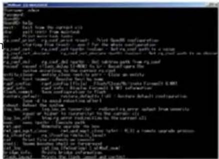
Image: Invigorating simulated Telnet session.
Camera Pan
- NAME
camera pan - Pans the camera left or right
• SYNOPSIS
camera pan { left [
- DESCRIPTION
Method used to pan the camera
- OPTIONS
left Move the camera left
right Move the camera right
stop Stop the camera movement
speed Optional integer from 1-24 that represents the speed (Default: 12)
- EXAMPLES
camera pan left
Pans the camera left at the default speed
camera pan right 20
Pans the camera right using a speed of 20
camera pan stop
Camera Tilt
- NAME
camera tilt - Tilts the camera up or down
• SYNOPSIS
camera tilt { up [
- DESCRIPTION
Method used to tilt the camera
- OPTIONS
up Move the camera up
down Move the camera down
stop Stop the camera movement
speed Optional integer from 1-20 that represents the speed (Default: 10)
- EXAMPLES
camera tilt Up Tilts the camera up at the default speed
camera tilt down 20 Tilts the camera up using a speed of 20
camera tilt stop Stops the tilt movement of the camera

natural_image
Close-up of a modern video camera with black base and white top (no visible text or symbols)Camera Zoom
- NAME
camera zoom - zoom the camera in or out
• SYNOPSIS
camera zoom { in [
- DESCRIPTION
Method used to zoom the camera
- OPTIONS
in Zoom in
out Zoom out
stop Stop the camera movement
speed Optional integer from 1-7 that represents the speed (Default: 3)
• EXAMPLES
camera zoom in - Zooms the camera in at the default speed
camera zoom out 7 - Zooms the camera out using a speed of 7
camera zoom stop - Stops the zoom movement of the camera
Camera Preset
• NAME
camera preset
• SYNOPSIS
camera preset recall <1-16>
camera preset store <1-16> [tri-sync <1-24>] [save-ccu]
- DESCRIPTION
Method used to recall and store camera presets
- OPTIONS
recall Recall preset
store Store preset
preset
Required value from 1-16 used to indicate the preset number
- EXAMPLES
camera recall 3 - Move camera to preset position 3
camera store - Store current camera position as preset 1
camera preset store 2 tri-sync 10 save-ccu
Store current camera position and CCU settings as preset 2, will recall using tri-sync at speed 10
camera preset store 4 tri-sync 15
Store current camera position as preset 4, will recall using tri-sync at speed 15
Camera Focus
- NAME
camera focus
• SYNOPSIS
camera focus { { near [
camera focus mode { auto | manual }
- DESCRIPTION
Method used to focus the camera
- OPTIONS
near Move the camera focus near (with optional speed)
far Move the camera focus far (with optional speed)
stop Stop the camera focus
mode Set the focus mode to auto or manual
speed Optional integer from 1-8 that represents the speed
• EXAMPLES
camera focus near
Focuses the
camera focus far 8
Focuses the
camera focus stop
camera near at the default speed
camera far at a speed of 8
Stops focus movement of the camera
Camera CCU
- NAME
camera ccu get - Gets the ccu settings
• SYNOPSIS
camera ccu get
- DESCRIPTION
Method used to get the ccu values of the connected camera
- OPTIONS
all Gets all supported CCU information
auto white balance Gets auto white balance
red_gain Gets red gain value
blue_gain Gets blue gain value
backlight_compensation Gets backlight compensation
auto_iris Gets auto-iris mode
iris Gets iris value gain
gain Gets gain value
detail Gets detail value
chroma Gets chroma value
- EXAMPLES
Camera ccu get iris Gets the iris value
camera ccu get red gain Gets the red gain
CCU Camera Scene
• NAME
camera ccu scene - Stores or recalls the ccu scene
• SYNOPSIS
camera ccu scene {recall {factory [1-6]|custom [1-3]} | store custom [1-3]}
- DESCRIPTION
Method used to get or set the ccu scene
- OPTIONS
recall Recalls a ccu scene
store Stores a custom ccu scene
custom A custom scene (can be stored or recalled)
factory A factory scene (can be recalled)
- EXAMPLES
camera ccu scene recall factory 2 - Recalls the factory scene stored at index 2

natural_image
Colorful abstract fan-shaped gradient design with no text or symbolsCamera CCU Set
• NAME
camera
ccu
set
- Sets and gets the CCU Settings
• SYNOPSIS
camera
ccu set
- DESCRIPTION
Method used to sets the ccu values
- OPTIONS
auto white balance Sets auto white balance to {on/off}
red_gain <0-255> Sets red gain value
blue_gain <0-255> Sets blue gain value
Backlight_compensation Sets backlight compensation {on/off}
auto_iris Sets auto iris {on/off}
iris Sets iris value <0-13>
gain Sets gain value <0-13>
detail Sets detail value <0-15>
chroma Sets chroma value <0-14>
- EXAMPLES
camera ccu set auto iris off
Sets the auto iris off
camera ccu set red gain 10
Sets the red gain to be 10
Camera Standby
• NAME
camera standby
• SYNOPSIS
camera standby { on | off | toggle }
- DESCRIPTION
Method used to put the camera in and out of standby
- OPTIONS
on put the camera into standby mode
off put the camera out of standby mode toggleswitches the standby mode state
• EXAMPLES
camera
standby off
camera
standby on
History
• NAME
history - command history
• SYNOPSIS
history [limit]
- DESCRIPTION
Since many of the programs read user input a line at a time, the command history is used to keep track of these lines and also recall historic information
• HISTORY NAVIGATION
The command history can be navigated using the up and down arrow keys. The up arrow will move up a single entry in the command history while the down arrow moves down in the command history.
• HISTORY EXPANSION
The command history supports the expansion functionality from which previous commands can be recalled from within a single session. History expansion is performed immediately after a complete line is read.
Listed below are examples of history expansion:
* !! Substitute the last command line.
* IN Substitute the Nth command line (absolute as per 'history' command)
* !-N Substitute the command line entered N lines before (relative)
* !! Substitute the last command line. * !N Substitute the Nth command line (absolute as per 'history' command) * !-N Substitute the command line entered N lines before (relative)
- EXAMPLES
history - Displays the current command buffer
history 5 - Sets the history command buffer to remember the last 5 unique entries

natural_image
Color wheel with eight-petaated rainbow segments (no text or symbols)Network Settings
- NAME
network
settings - get current network settings
• SYNOPSIS
network
settings {get} - DESCRIPTION
Method used to get the current network settings of the device
- OPTIONS
get Get the current network settings for the machine
• EXAMPLES
network settings get
MAC Address: 00:04:a3:85:0a:ee
IP Address: 10.10.8.116
Netmask: 255.255.255.0
Gateway: 10.10.8.100
Returns the current network settings for mac addres, ip address, netmask, and gateway
chemical
Molecular structure diagram showing green and red atoms connected by bonds, likely representing a coordination complex or molecular modelNetwork Ping
- NAME
network ping - send ICMP ECHO_REQUEST to network hosts
• SYNOPSIS
network ping [count
- DESCRIPTION
Use the ICMP protocol's mandatory ECHO REQUEST datagram to elicit an ICMP ECHO RESPONSE
from a host or gateway. ECHO REQUEST datagrams have an IP and ICMP header, followed by a struct
timeval and then an arbitrary number of pad bytes used to fill out the packet.
- OPTIONS
count Stop after sending count ECHO REQUEST packets. With deadline option, ping waits for count
ECHO REPLY packets, until the timeout expires. The default is 5.
destination The destination IP address where the ECHO_REQUESTS are sent
size The data size of the ICMP packet to send. The default is 56 bytes
• EXAMPLES
network ping 192.168.1.1
Attempt to send 5 ICMP ECHO_REQUESTs with data size 56 to the host at 192.168.1.1
network ping count 10 size 100 192.168.1.1
Attempt to send 10 ICMP ECHO_REQUESTs with data size of 100 to the host at 192.168.1.1
System Factory-Reset
- NAME
system factory-reset - Gets or sets factory reset status
• SYNOPSIS
system factory-reset {get|on|off}
- DESCRIPTION
Method used to get or set the factory reset status
- OPTIONS
get Get the current factory reset status
on Enable factory reset on reboot
off Disable factory reset on reboot
- EXAMPLES
system factory-reset get
factory-reset (software):
off
factory-reset (hardware): [Hardware reset is designated by rear panel DIP switches in down position] off
Returns the factory reset status
System factory-reset on
factory-reset (software): on
factory-reset (hardware): off
Enables factory reset upon reboot
System Reboot
- NAME system reboot - Reboots system
- SYNOPSIS
system reboot [
]
• DESCRIPTION Method used to reboot system - OPTIONS
seconds
The number of seconds to delay the reboot
• EXAMPLES reboot Reboot system immediately reboot 30 Reboot the system in 30 seconds
Help
- NAME help - display an overview of the CLI syntax
- SYNOPSIS help
- DESCRIPTION
Display an overview of the command line syntax

Version
- NAME version - display the system version information
- SYNOPSIS version
• DESCRIPTION Display an overview of the command line syntax
• EXAMPLES version Returns the current software version
Exit
- NAME
exit
• SYNOPSIS exit - DESCRIPTION
Ends the current API command session. If the session is over telnet, the session is ended and the socket is closed. If the session is over serial, a new session is started.
COMPLIANCE AND CE DECLARATION OF CONFORMITY - ROBOSHOT HDMI CAMERAS
Compliance testing was performed to the following regulations:
• FCC Part 15 (15.107, 15.109), Subpart B
• ICES-003, Issue 4: 2004
• EN 55022 A: 2006 + A1: 2007
• KN24 2008 (CISPR 24: 1997 + A1: 2000 + A2: 2002)
• KN22 2008 (CISPR 22: 2006)
• EMC Directive 2004/108/EC
• EN 55024: A2: 2003
• IEC 60950-1:2005 (2nd Edition); Am 1:2009
• EN 60950-1:2006+A11:2009+A1:2010+A12:2011
Class A
Class A
Class A
Class A
Class A
Class A
Class A
Safety
Safety

natural_image
Two views of a white handheld device with a black top and a silver top, showing no visible text or symbols.


FC
FCC Part 15 Compliance
This equipment has been tested and found to comply with the limits for a Class A digital device, pursuant to Part 15, Subpart B, of the FCC Rules. These limits are designed to provide reasonable protection against harmful interference when the equipment is operated in a commercial environment. This equipment generates, uses, and can radiate radio frequency energy and, if not installed and used in accordance with the instruction manual, may cause harmful interference to radio communications. Operation of this equipment in a residential area is likely to cause harmful interference in which case the user will be required to correct the interference at his/her own expense.
Operation is subject to the following two conditions: (1) This device may not cause interference, and (2) This device must accept any interference including interference that may cause undesired operation of the device.
Changes or modifications not expressly approved by Vaddio can affect emission compliance and could void the user's authority to operate this equipment.

Industry
Canada
Industrie
Canada
ICES-003 Compliance
This digital apparatus does not exceed the Class A limits for radio noise emissions from digital apparatus set out in the Radio Interference Regulations of the Canadian Department of Communications.
This product has been evaluated for Electromagnetic Compatibility under the EMC Directive for Emissions and Immunity and meets the requirements for a Class A digital device. In a domestic environment this product may cause radio interference in which case the user may be required to take adequate measures.
Standard(s) To Which Conformity Is Declared:
EMC Directive 2004/108/EC
EN 55022:2010
EN 55024: 1998 + Amendments A1: 2001 + A2: 2003
• EN 61000-4-2: 1995 + Amendments A1: 1998 + A2: 2001
• EN 61000-4-3: 2006 + A1: 2008
• EN 61000-4-4: 2004 + Corrigendum 2006
• EN 61000-4-5: 2006
• EN 61000-4-6: 2009
• EN 61000-4-8: 2010
• EN 61000-4-11:2004
KN24 2008 (CISPR 24: 1997 + A1: 2000 + A2: 2002)
EN 61000-4-2
EN 61000-4-3
EN 61000-4-4
EN 61000-4-5
EN 61000-4-6
EN 61000-4-8
EN 61000-4-11
IEC 60950-1:2005 (2nd Edition); Am 1:2009
EN 60950-1:2006+A11:2009+A1:2010+A12:2011
Conducted and Radiated Emissions
Immunity
Electrostatic Discharge
Radiated Immunity
Electrical Fast Transients
Surge Immunity
Conducted Immunity
Power Frequency Magnetic Field
Voltage Dips, Interrupts and Fluctuations
IT Immunity Characteristics
Electrostatic Discharge
Radiated Immunity
Electrical Fast Transients
Surge Immunity
Conducted Immunity
Power Frequency Magnetic Field
Voltage Dips, Interrupts and Fluctuations
Safety
Safety
WARRANTY INFORMATION
(See Vaddio Warranty, Service and Return Policies posted on vaddio.com for complete details):
Hardware* Warranty: Two (2) year limited warranty on all parts and labor for Vaddio manufactured products. Vaddio warrants its manufactured products against defects in materials and workmanship for a period of two years from the day of purchase, to the original purchaser, if Vaddio receives notice of such defects during the warranty. Vaddio, at its option, will repair or replace products that prove to be defective. Vaddio manufactures its hardware products from parts and components that are new or equivalent to new in accordance with industry standard practices.
Exclusions: The above warranty shall not apply to defects resulting from improper or inadequate maintenance by the customer, customers applied software or interfacing, unauthorized modifications or misuse, mishandling, operation outside the normal environmental specifications for the product, use of the incorrect power supply, modified power supply or improper site operation and maintenance. OEM and Special Order products manufactured by other companies are excluded and are covered by the manufacturer's warranty.
Vaddio Customer Service: Vaddio will test, repair, or replace the product or products without charge if the unit is under warranty. If the product is out of warranty, Vaddio will test then repair the product or products. The cost of parts and labor charge will be estimated by a technician and confirmed by the customer prior to repair. All components must be returned for testing as a complete unit. Vaddio will not accept responsibility for shipment after it has left the premises.
Vaddio Technical Support: Vaddio technicians will determine and discuss with the customer the criteria for repair costs and/or replacement. Vaddio Technical Support can be contacted through one of the following resources: e-mail support at support@vaddio.com or online at vaddio.com.
Return Material Authorization (RMA) Number: Before returning a product for repair or replacement request an RMA from Vaddio's technical support. Provide the technician with a return phone number, e-mail address, shipping address, product serial numbers and original purchase order number. Describe the reason for repairs or returns as well as the date of purchase. See the General RMA Terms and Procedures section for more information. RMA's are valid for 30 days and will be issued to Vaddio dealers only. End users must return products through Vaddio dealers. Include the assigned RMA number in all correspondence with Vaddio. Write the assigned RMA number clearly on the shipping label of the box when returning the product. All products returned for credit are subject to a restocking charge without exception. Special Order product are not returnable.
Voided Warranty: The warranty does not apply if the original serial number has been removed or if the product has been disassembled or damaged through misuse, accident, modifications, use of incorrect power supply, use of a modified power supply or unauthorized repair.
Shipping and Handling: Vaddio will not pay for inbound shipping transportation or insurance charges or accept any responsibility for laws and ordinances from inbound transit. Vaddio will pay for outbound shipping, transportation, and insurance charges for all items under warranty but will not assume responsibility for loss and/or damage by the outbound freight carrier. If the return shipment appears damaged, retain the original boxes and packing material for inspection by the carrier. Contact your carrier immediately.
Products not under Warranty: Payment arrangements are required before outbound shipment for all out of warranty products.
Other General Information:
Care and Cleaning
Do not attempt to take this product apart at any time. There are no user-serviceable components inside.
- Do not spill liquids in the product
- Keep this device away from food and liquid
- For smears or smudges on the product, wipe with a clean, soft cloth
- Use a lens cleaner on the lens...
- Do not use any abrasive chemicals.
Operating and Storage Conditions:
Do not store or operate the device under the following conditions:
• Temperatures above 40^ C ( 104^ F) or temperatures below 0^ C ( 32^ F)
• High humidity, condensing or wet environments
• In inclement weather
- Between converging tectonic plates
- Dry environments with an excess of static discharge
• Within the Thermosphere (temperature issue)
• Under severe vibration
Unintentionally Mostly Blank
vaddio
Toll Free: 800-572-2011 · Phone: 763-971-4400 · FAX: 763-971-4464
www.vaddio.com
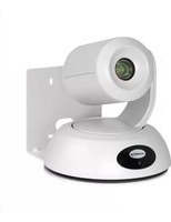
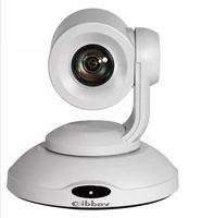
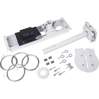
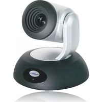
- Contents
- OVERVIEW
- Intended Use:
- Save These Instructions:
- Important Safeguards:
- UNPACKING THE CAMERA SYSTEMS
- RoboSHOT 12 HDMI Camera
- Part Number 999-9940-000 (North America)
- Part Number 999-9940-001 (International)
- RoboSHOT 30 HDMI Camera (Black)
- Part Number 999-9943-000 (North America)
- Part Number 999-9943-001 (International)
- RoboSHOT 30 HDMI Camera (White)
- Part Number 999-9943-000W (North America)
- RoboSHOT 12 HDMI Camera (White)
- Part Number 999-9943-001W (International)
- 4) Multi-Color LED:
- Image: RoboSHOT 30 HD PTZ Camera
- RoboSHOT HDMI Switch Settings
- Drawing: DIP Switch and Resolution Label on the Bottom of the RoboSHOT
- Setting the RoboSHOT Switch Gear:
- DIP Switch Settings Further Explained (DSSFE):
- INSTALLATION BASICS:
- Pre-Installation
- RS-232 Cabling Notes:
- Determine Camera Mount Location and Mount
- Power Up
- CONTROLLING THE CAMERA
- IR Remote Commander
- Telnet Control Examples
- Compatible Web Browsers
- DHCP IP Set-up (Dynamic Host Configuration Protocol)
- Static IP Set-up:
- Screen Shot: Login
- Screen Shot: Camera Control Page
- Screen Shot: Storing Presets
- Screen Shot: Admin login from the Camera Control Page
- Screen Shot: Admin Menu - Camera Settings
- Screen Shot: Admin Menu - Room Labels
- Screen Shot: Admin Menu - DHCP Network Configuration
- Screen SHOT: Admin Menu - Static IP Configuration
- Screen SHOT: Admin Menu - Security
- Screen Shot: Admin Menu - Diagnostics
- Screen Shot: Admin Menu - System
- Screen Shot: Admin Menu - Update Confirmation
- Screen Shot: Admin Menu - Update in Progress
- Screen Shot - Admin Menu - Help
- The Next Sections:
- COMMUNICATION SPECIFICATION
- COMMAND SETTING VALUES
- Exposure Control
- TELNET SERIAL COMMAND API
- Set Example
- Get Example
- Syntax Error Example
- Telnet Command List
- Camera Home
- Camera Pan
- Camera Tilt
- - NAME
- • SYNOPSIS
- - DESCRIPTION
- - OPTIONS
- - EXAMPLES
- Camera Zoom
- • EXAMPLES
- Camera Preset
- • NAME
- Camera Focus
- Camera CCU
- CCU Camera Scene
- Camera CCU Set
- Camera Standby
- History
- Network Settings
- Network Ping
- System Factory-Reset
- System Reboot
- Help
- Version
- Exit
- COMPLIANCE AND CE DECLARATION OF CONFORMITY - ROBOSHOT HDMI CAMERAS
- FC
- FCC Part 15 Compliance
- ICES-003 Compliance
- WARRANTY INFORMATION
- Other General Information:
- Care and Cleaning
- Operating and Storage Conditions:
Brand : Vaddio
Model : RoboSHOT 30 HDMI
Category : Video Conferencing System