I3-380IP04 - Security Camera Provision-ISR - Free user manual and instructions
Find the device manual for free I3-380IP04 Provision-ISR in PDF.


| Product Type | Security Camera |
| Model | I3-380IP04 |
| Brand | Provision-ISR |
| Resolution | 2 Megapixels (1920x1080) |
| Night Vision | Infrared up to 30m |
| Lens | 4mm Fixed |
| Field of View | 80° Horizontal |
| Power Supply | PoE (802.3af) or 12V DC |
| Power Consumption | 4W (max) |
| Dimensions | 160 x 60 x 65 mm |
| Weight | 400g |
| Ingress Protection | IP67 |
| Mounting Type | Wall or Ceiling |
| Video Compression | H.265+/H.265/H.264 |
| Network Interface | RJ-45 10/100Mbps |
| Storage | MicroSD card up to 256GB |
| Audio | Built-in microphone |
| Maintenance | Clean lens with soft dry cloth; avoid water |
| Safety | Use only approved power adapter; keep away from heat sources |
| Spare Parts | Contact manufacturer for replacement parts |
| General Information | Recommended for indoor/outdoor surveillance |
Frequently Asked Questions - I3-380IP04 Provision-ISR
User questions about I3-380IP04 Provision-ISR
0 question about this device. Answer the ones you know or ask your own.
Ask a new question about this device
Download the instructions for your Security Camera in PDF format for free! Find your manual I3-380IP04 - Provision-ISR and take your electronic device back in hand. On this page are published all the documents necessary for the use of your device. I3-380IP04 by Provision-ISR.
USER MANUAL I3-380IP04 Provision-ISR
Now you can see!

natural_image
Exterior view of multiple surveillance cameras and security cameras (no visible text or labels)IP Series
CAMERA USER MANUAL
PROVISION-ISR
I3-380IP04
User Manual
720P 30m IR Fixed Lens IP Bullet Camera
For H.264 IP Camera
All rights reserved
Before use this product
- Before operation, we strongly advise users to read this manual and keep it properly for using later.
- This is product instructions not quality warranty. We may reserve the rights of amending the typographical errors, inconsistencies with the latest version, software upgrades and product improvements, interpretation and modification. These changes will be published in the latest version without special notification.
- When this product is in use, the relevant contents of Microsoft, Apple and Google will be involved in. The pictures and screenshots in this manual are only used to explain the usage of our product. The ownerships of trademarks, logos and other intellectual properties related to Microsoft, Apple and Google belong to the above-mentioned companies.
Table of Contents
1 Introduction....1
1.1 Summarization.... 1
1.2 Check Package Content .... 1
1.3 Connection .... 1
2 Installation 2
2.1 Install IP-CAM to Ethernet Network....2
2.2 CMS and IP-Tool Installation....2
3 IE Remote Access....3
3.1 LAN....3
3.1.1 Access through IP-Tool 3
3.1.2 Directly Access through IE....4
3.2 WAN....6
4 Remote Preview....7
4.1 The Remote Preview Interface 7
4.2 Record Playback....7
4.3 Right-click Function 8
4.4 Snap Pictures....8
5 Remote Live Surveillance....10
5.1 System Configuration....10
5.1.1 Basic Information 10
5.1.2 Date & Time Configuration....11
5.2 Video Configuration....11
5.2.1 Camera Configuration 11
5.2.2 Video Stream....12
5.2.3 Time Stamp....12
5.2.4 Video Mask 13
5.3 Alarm Configuration....13
5.3.1 Motion Detection Area 13
5.3.2 Motion Detection Trigger....14
5.3.3 Motion Detection Schedule 15
5.4 Network Configuration....15
5.4.1 Port 15
5.4.2 Wired....16
5.4.3 NET Traversal Configuration 16
5.4.4 Server Configuration....17
5.4.5 IP Notify 18
5.4.6 DDNS Configuration....18
5.4.7 RTSP 22
5.4.8 UPNP 22
5.4.9 Mail Setting....23
5.4.10 FTP 24
5.5 Advanced Configuration....24
5.5.1 User Configuration....25
5.5.2 Security Configuration....26
5.5.3 Configure Backup & Restore....27
5.5.4 Reboot Device 27
5.5.5 Upgrade 28
6 Mobile Surveillance 29
6.1 Network Configuration....29
6.2 By Phones with iPhone OS 30
6.3 By Phones with Android....36
7 Use method for IP-TOOL....39
Q & A 42
Specification 44
1 Introduction
1.1 Summarization
This IP-CAMERA (short for IP-CAM) is designed for high performance CCTV solutions. It adopts state of the art video processing chips. It utilizes most advanced technologies, such as video encoding and decoding technology, complies with the TCP/IP protocol, SoC, etc to ensure this system more stable and reliable. This unit consists of two parts: the IP-CAM device and central management software (short for CMS). The CMS centralizes all devices together via internet or LAN and establishes a sound surveillance system to realize unified management and remote operation to all devices in one network.
This product is widely used in banks, telecommunication systems, electricity power departments, law systems, factories, storehouses, uptowns, etc. In addition, it is also an ideal choice for surveillance sites with middle or high risks.
1.2 Check Package Content
Please check your accessories as per packing list after you receive your device.
| Accessories | Description |
| IP-CAMERA | The device without Lens |
| Quick Start Guide | The Brief instructions of the product |
| CD | CD-ROM with software and manual |
| Screws and screwdriver | For installation |
1.3 Connection
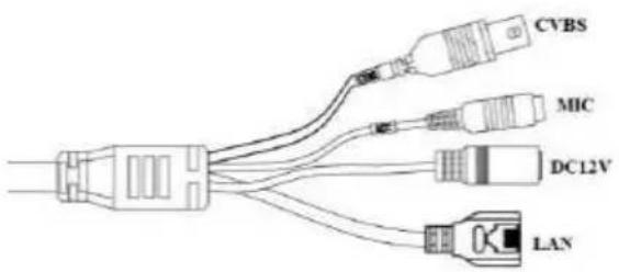
CVBS: connect to monitor MIC: connect to MIC
DC12V: connect to power supply
LAN: network port (some models support PoE power supply)
Some models of this series support internal focusing. The steps are as follows:
2 Installation
2.1 Install IP-CAM to Ethernet Network
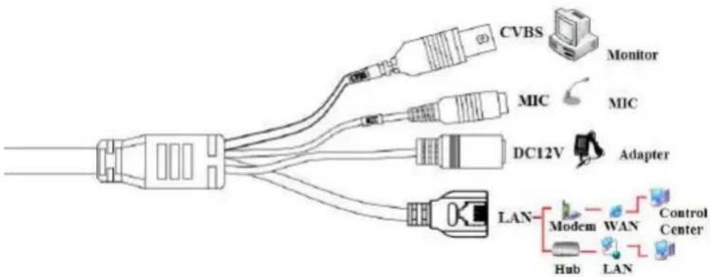
The connection of digital video server is show below.
flowchart
graph TD
    A["LAN"] --> B["DC12V"]
    A --> C["MIC"]
    A --> D["Monitor"]
    A --> E["Adapter"]
    A --> F["LAN"]
    A --> G["Modem"]
    A --> H["WAN"]
    A --> I["Control Center"]
    A --> J["Hub"]
    A --> K["LAN"]
Figure 2-1 Connection
Please connect the PC and IP-CAMERA in accordance with the above picture.
The connection steps are shown as below:
Step 1: Connect the monitor, microphone and network to the device.
Step 2: Connect the power supply.
Step 3: Install the device.
2.2 CMS and IP-Tool Installation
Find CMS software from CD and then double click “Setup.exe” file to pop up installation wizard.
Install the software according to the prompts in the wizard. After you complete the installation, you will see the CMS and IP-Tool icon on the desktop. Please see the user manual of this software for more details.
If you need to install IP-Tool separately, please double click IP-Tool installation package and install it according its wizard prompts. After you finish installing, double click IP-Tool icon to start IP-Tool.
3 IE Remote Access
IP-Cam can be connected through LAN or WAN. Here only take IE browser (6.0) for example. The details are as follows:
3.1 LAN
In LAN, there are two ways to access IP-Cam: 1. Access through IP-Tool; 2. Directly access through IE browser.
3.1.1 Access through IP-Tool
Step 1: Make sure the PC and IP-Cam are connected to the LAN and the IP-Tool is installed in the PC from the CD.
Step 2: Use IP-Tool to modify the network of IP-Cam. Then, double click the icon on the desktop to run this software as shown below:
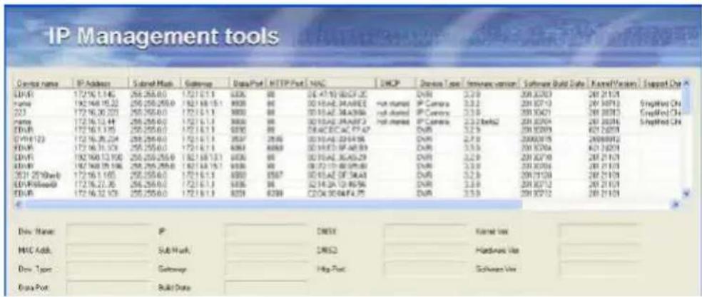
After starting IP-Tool, clicking the IP-Cam name in the list can display the detail information of IP-Cam. If you cannot confirm which one is yours, please shut off the electricity of the IP-Cam and then power on it. When shutting off the power, the device information will disappear. When powering on, the device information will emerge. Well, this device is the used device. Right click the device information and select “network setup”. Then the network setup window will pop up as shown below:
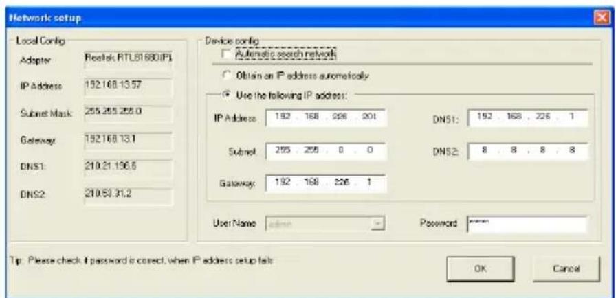
For example, the network segment of this computer is 192.168.13.x under the local config table. So, please modify the IP address, Gateway of IP-Cam which must be in the same network segment with the computer. Modifying the network, you have to input the password and click "OK" button to save the setting.
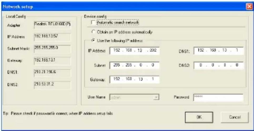
Note: The default user name is: admin. The default password is: 123456.
The new IP address of this device will display as follows after modification.
Step 3: Use the IP-Tool to login the IP-Cam.
Right-click the IP address and select “browse with IE” or double click the information of this device. The IE browser will auto download the Active X control. If the IE browser cannot download the Active X control, please refer to Q4 of Chapter 9. After the completion of the installation of the Active X control, a login window will pop up.
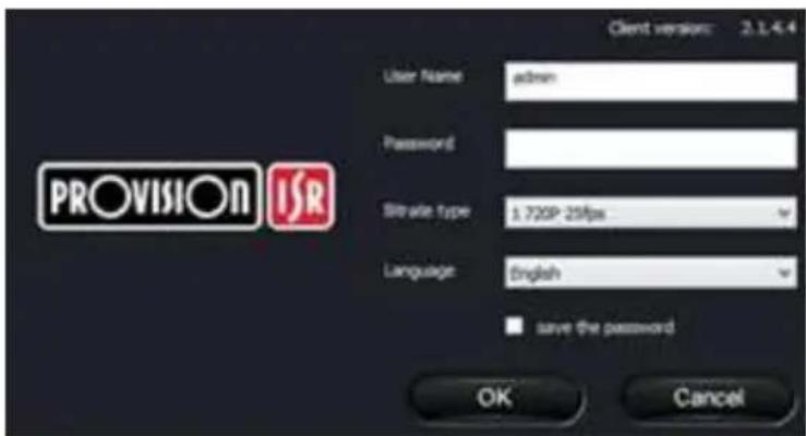
Input User name and password and then click "OK" button to login.
Note: You can also use the modified IP address of the IP-Cam. Input the IP address in the IE browser bar and then click “Enter” to access IP-Cam. The default user name is admin. The default password is 123456.
3.1.2 Directly Access through IE
The default network settings are as shown below:
IP address: 192.168.226.201
Subnet Mask: 255.255.255.0
Gateway: 192.168.226.1
HTTP: 80
Data port: 9008
The first time you used the IP-CAM, you should connect the device with the above default settings. Here take the Windows XP OS for example to introduce the setting steps.
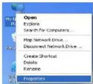
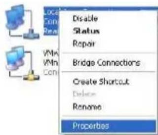
Step 1: Manual setup the IP address of the PC, the network segment should be as same as the default settings of IP-CAM. Right click “My Network Places” icon on the desktop→select “properties” as shown in the left figure. Right click “Local Area Connection” at the popup window and then select “property” as shown in the right figure.
Select “Internet Protocol (TCP/IP)” in the “General” tabs, click “properties” in the next window and then manual input network address information of the PC in the following popup window.
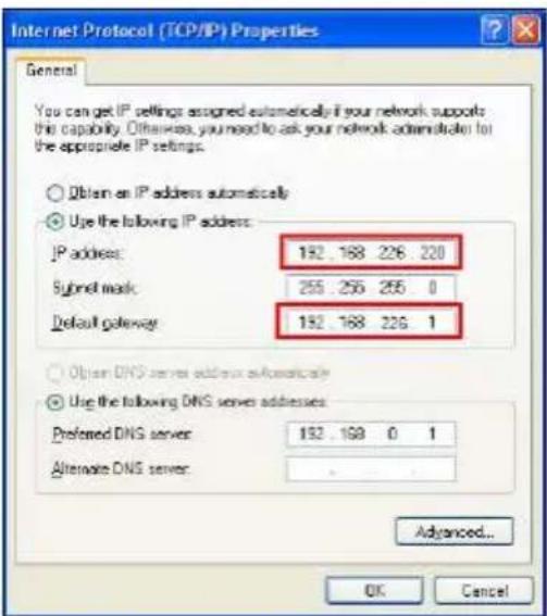
Step 2: Open the IE Browser, input the default address of IP-CAM and confirm. This will take you to the Active X control downloading interface. If IE browser can't download Active X control, please refer to Q4 of chapter 9.
Step 3: After downloading Active X control, the login dialog box will pop up.
Step 4: Input user name and password in the login dialog box and click “OK” button to enter into the live interface. You can manage and setup the IP-CAM in the IE client, such as changing IP address, upgrading the software., etc.
3.2 WAN
Access through router or virtual server
Step1: Make sure the device is well connected in LAN. Then enter into System Configuration→Network configuration→Basic configuration to setup the port number as shown in Fig 3-1:
Step 2: Enter into System Configuration→Network configuration→IP configuration interface to change IP address as shown in Fig 3-2:
Notice: The steps above should be saved after the change of the port and IP address.
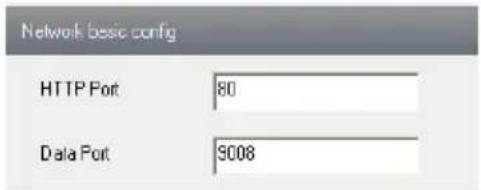
Fig 3-1 Port setup
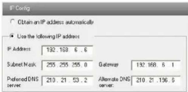
Fig 3-2 IP setup
Step 3: Enter into the router's management interface through IE browser and forward the IP address and port of IP-CAM in the "virtual server". The name depends on the router. Please refer to Fig 3-3:
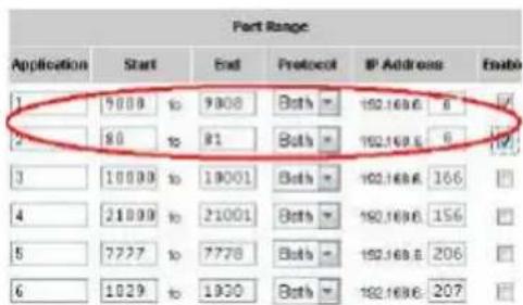
Fig 3-3 Router setup
Step 4: Open the IE browser and input its WAN IP and http port to access. The following steps are as same as “Step 2, 3 and 4” of Chapter 3.1.2 in LAN.
4 Remote Preview
4.1 The Remote Preview Interface
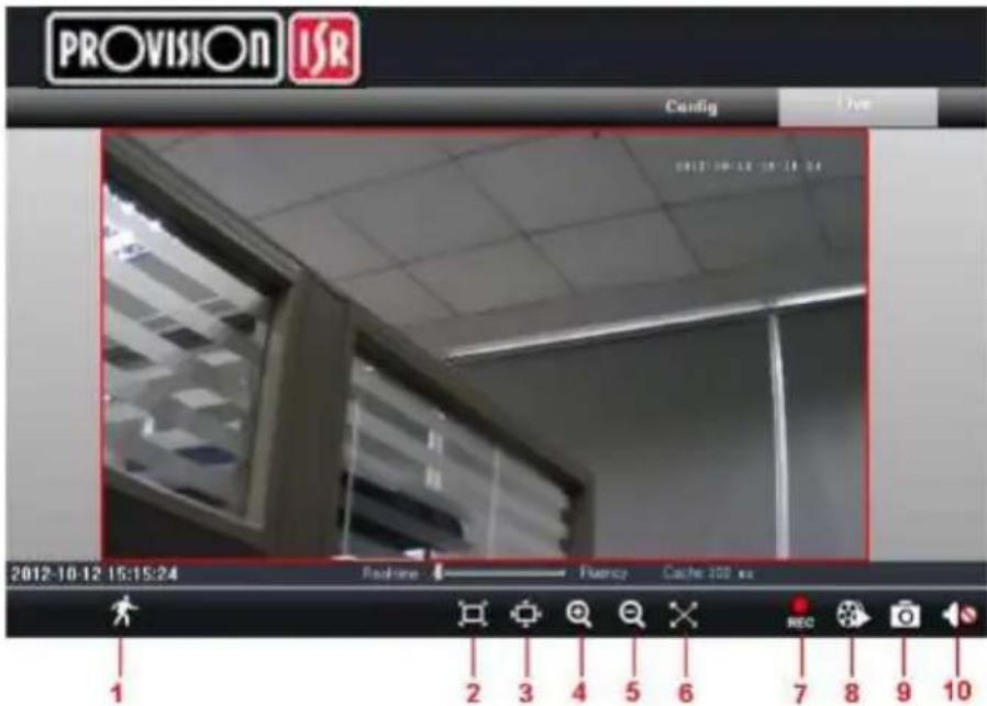
Fig 4-1 Remote Preview
| 1 | People icon | 2 | Fix size | 3 | Zoom in |
| 4 | Zoom in | 5 | Zoom out | 6 | Full screen |
| 7 | Start record | 8 | Playback | 9 | Snap |
| 10 | Enable audio |
- When motion detection alarm is triggered, the people icon turns red.
- Click 📄 icon to zoom in the preview image to suitable size. Drag the cursor on the enlarged image to view suitable preview area. Click 🔒 icon to zoom out the enlarged image. Click ✕ icon to full-screen the live image.
- Clicking REC icon will appear a save path window and the record file can save on your PC.
Note: On Window 7 and Window Vista, user can not record or snap pictures until UAC function is disabled. Please refer to following steps: Start—Control panel—User accounts—Change user account control settings in which user needs to drag the scale to Always notify end and then click “OK” button to save.
4.2 Record Playback
Click 📄icon and refer to Fig 4-2:
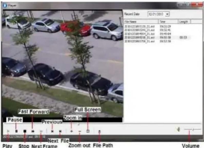
Fig 4-2 record playback interface
After selecting the record date, the record files will be displayed in the record file list box. User can double click a certain record file to playback or check a certain file. Then click Play button to do playback.
4.3 Right-click Function
Clicking right mouse will appear a pull-down list as below: Stream: There are two options.
Turn off the live: Click this item will close present live preview.
Enable audio: Enable remote audio transmission. Users can hear the audio from the IP-CAM.
Full screen: The live preview picture will full-screen display. Double click or click right mouse to return to the previous interface.
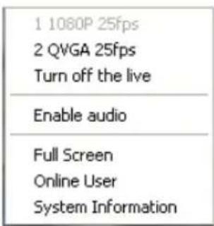
Fig 4-3 Right key sub-menu
Online user: Display user's list connect to the device.
System information: Display the device information: device name, firmware version, software build date, kernel version and hardware version.
4.4 Snap Pictures
- Select the picture number, and then click “Snap” icon as shown in the Fig 4-4:
- User can snap multiple pictures. Select the picture number from Frame pull down list box, such as 3, and check "Title" and "Time" to show capture title and time on the snap pictures simultaneously. Refer to Fig 4-5:
- Click "Browse" to set saving path; Click "Save" to save pictures to HDD on the computer; Click "Printer setup" to set the printer and print the snap pictures; drag the
scroll bar to view all snapped pictures.
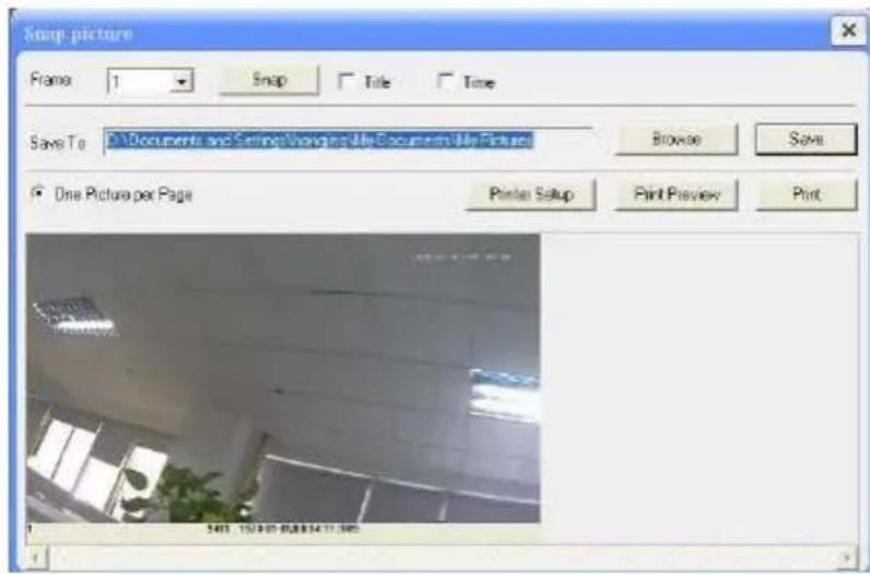
Fig 4-4 Single Snap
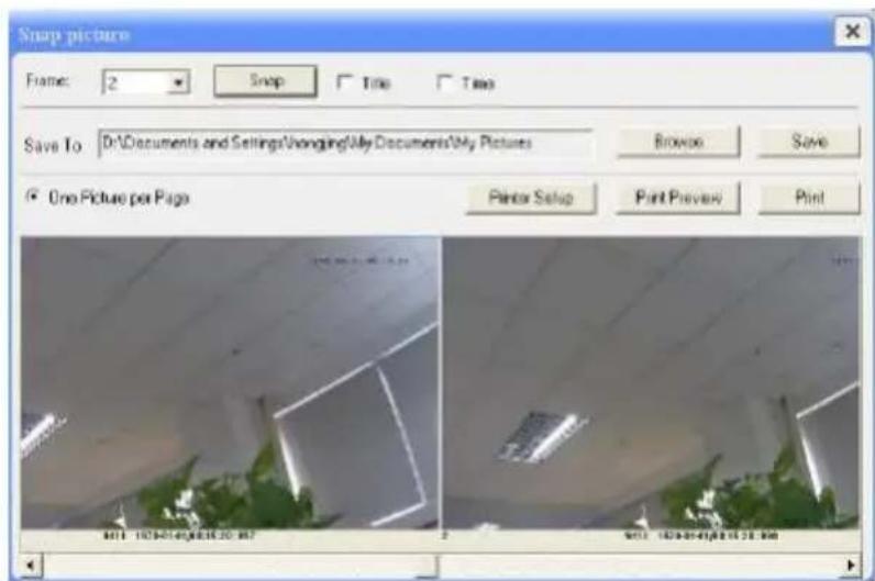
Fig 4-5 Multi-picture Snap
5 Remote Live Surveillance
Functions of remote configurations include: System Configuration, Video Configuration, Alarm Configuration, Network Configuration and Advanced Configuration. User should firstly select the menu on the left, and then setup the relative parameters. When a user setup parameters of a certain device, other users can not setup this device.
5.1 System Configuration
The “System configuration” includes two submenus: Basic Information and Date & Time.
5.1.1 Basic Information
In the “Basic Information interface, user can setup the device name and also can check the relative information of the server
Setting steps:
- Clicking the "Config" icon will appear the menu list.
- Clicking the "Basic Information" will pop up a window as shown in Fig 5-1:
- Input the name of the device in the "Device name" text box.
- Press the "Save" button to save the settings.
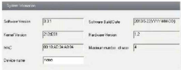
Fig 5-1 Basic Information Config
Please refer to the following table for parameters and instructions of server basic configuration.
| Parameter | Meaning |
| Software version | The software of the device |
| Software build date | The software build date of the device |
| Kernel version | The kernel version of the device |
| Hardware version | The hardware version of the device |
| Mac Address | MAC address of device |
| Maximum number of user | Support max 4 users to access |
| Device name | Name of the device. |
5.1.2 Date & Time Configuration
Setting steps:
- Enter into "System Configuration" → "Date & Time". Refer to Fig 5-2:
- Select "Modify Time" to self-define time. Choose "Time Zone" according to user's location.
- Set DST as required.
- User can setup time by select the "Synchronize with NTP Server".
- Press the "Save" button to save the settings.
![Date and Time setting Set manually 6/5/2013 5:00:37 PM Modify time Time Zone [GMT] Greenwich Mean Time : Dublin, Edinburgh, Lisbon, London Daylight setting DST Enable DST Mode Week Mode Time offset 1 Slait month Jan End month Jan First Sun First Sun Slait Time 12:00:00 AM End Time 12:00:00 AM NTP server setting Synchronize with NTP Server NTP Server line windows con Update Now](/content/2026/05/1046794/images/f64990b1628a1fa69d8c538caffa9576d610cb0ae62adce6965ee3296fbd1733.jpg)
Fig 5-2 Date &Time Config
5.2 Video Configuration
Camera Configuration includes four submenus: Camera Configuration, Video Stream, Time Stamp and Video Mask.
5.2.1 Camera Configuration
Setting steps:
- Enter into "Video Configuration" "Camera" interface as shown in Fig 5-3:
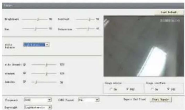
Fig 5-3 Basic Configuration
- User can adjust Brightness, Contrast, Hue and saturation of the picture.
- Select white balance mode.
- Sharpen, denoise, white balance, frequency, CVBS format and Day-Night mode are adjustable.
- User also can enable the image mirror and image overturn function.
- Press the "Save" button to save the settings.
5.2.2 Video Stream
- Enter into "Video configuration"→ "Video Stream" to see a interface as shown in Fig 5-4:
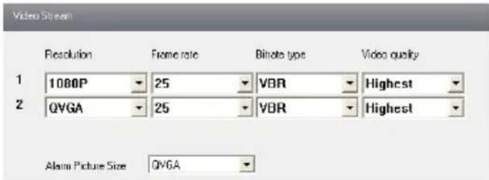
Fig 5-4 Video Stream
- Select the resolution of the single frame image at the "Resolution" pull down list.
- Select the quantity of video per second at the "Frame rate" pull down list.
- Select the data stream type at the "Bit rate type" pull down list.
- Set the video quality at the "Video quality" pull down list.
- Select alarm picture size.
- Press the "Save" button to save the settings.
5.2.3 Time Stamp
Enter into "Video configuration"→"Time Stamp" to display the interface as shown in Fig 5-5:
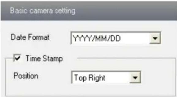
Fig 5-5 Time Stamp
- Select Date Format to show in the live image.
- Set time stamp. If time stamp is enabled, the live pictures with the time stamp will display. There are four positions of time stamp can be set. Top left, top right, bottom left and bottom right.
- Press the "Save" button to save the settings.
5.2.4 Video Mask
You can set 4 mask area at most.
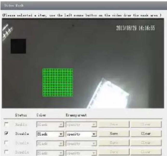
Fig 5-6 Video Mask
Enable the mask, select color and transparent of the mask area and then drag the mouse to set the mask area. This will take you see a gridding area. After that, click "Save" button to save the settings. Then you will see a mask area on the live image.
5.3 Alarm Configuration
Alarm configuration includes three submenus: Motion Detection Area, Motion Detection Trigger and Motion Detection Schedule.
5.3.1 Motion Detection Area
- Enter into "Alarm configuration"→"Motion Detection Area" to see a interface shown as Fig 5-7:
- Move the "Sensitivity" scroll bar to setup the motion trace sensitivity.
- Check "Add", press the "Ctrl" button and move mouse to select the motion detection area; Select "Erase" and move the mouse to clear all motion detection area.
- Press the "Save" button to save the settings.
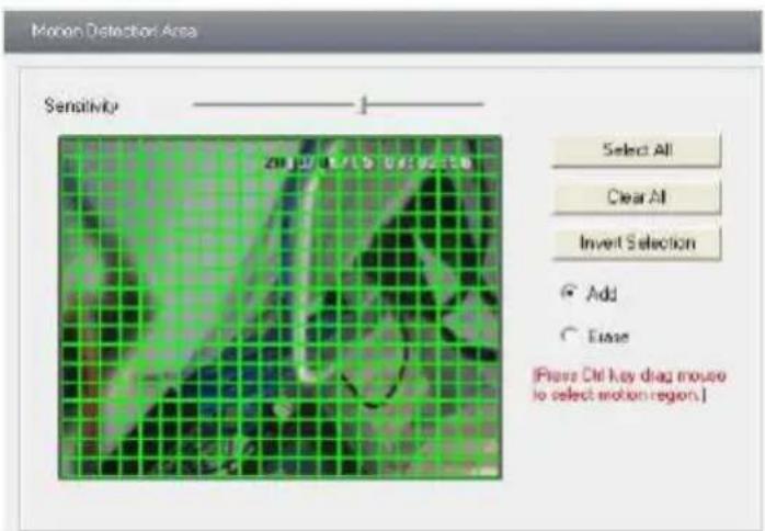
Fig 5-7 Motion Detection Area
5.3.2 Motion Detection Trigger
- Enter into "Alarm Configuration"→ "Motion Detection Trigger" to display a interface as shown in Fig 5-8:
- Check "Enable alarm" check box. Then all functions under this interface will be activated.
- Trigger Email: Check "Attach picture" and select email addresses in the "Receival email address" text box (Email address shall be set first in the Mail config interface). Then the triggered snap pictures will be sent into those address. User also can define the subject and content of the email.
- Trigger FTP: Check "Uploading picture". Then the triggered snap pictures will be sent into FTP server address.
Note: Please refer to FTP configuration chapter for more details.
- Press the "Save" button to save the settings.
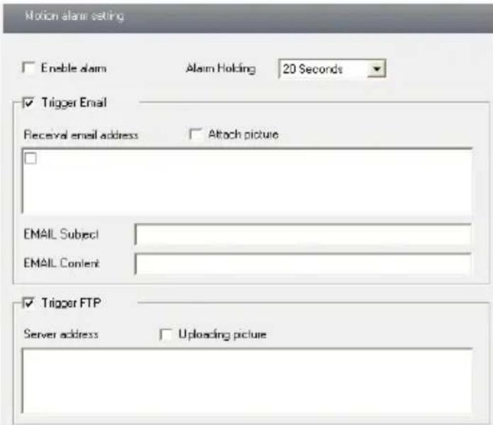
Fig 5-8 Motion Alarm Trigger
5.3.3 Motion Detection Schedule
Enter into "Alarm configuration" "Motion Detection schedule" interface as shown in Fig 5-9:
Week schedule
User could set the alarm time from Monday to Sunday for alarm everyday in one week. Note: The lengthwise means one day of a week; the rank means 24 hours of a day. Click on the pane to set the alarm hours. Green means selected area. Blank means unselected area.
"Add": add the schedule for a special day.
"Erase": delete holiday schedule
Day schedule
User could set alarm time for alarm at a certain time of special day, such as holiday.
- Select a date at the "Date" pull down list, press "Add" button to add that date to the list box on the right side and then move the scroll bar to set the schedule of that day.
- Select a date in the list box on the right side, and press "Erase" to remove the schedule on that day.
Press the "Save" button to save the settings.
Note: Holiday schedule is prior to Week schedule.
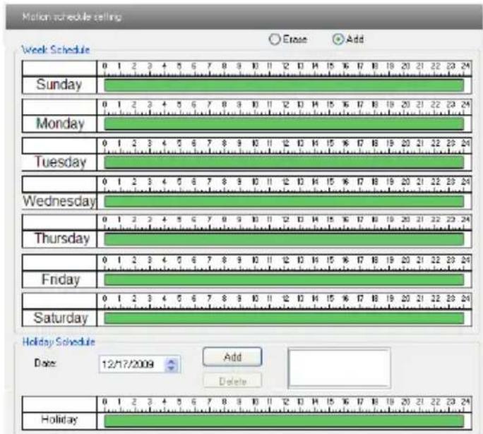
Fig 5-9 Motion Detection Schedule
5.4 Network Configuration
Network configuration includes ten submenus: Port, Wired, NET traversal Config, Server Configuration, IP Notify, DDNS Config, RTSP, UPNP, Mail Setting and FTP.
5.4.1 Port
- Enter into "Network config" "Port" to see the interface as shown in Fig 5-10:
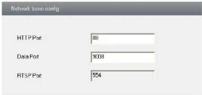
Fig 5-10 Port Config
- Input port number for IE access in the "HTTP Port" textbox.
- Input the port number for audio & video transmission in the "Data Port" textbox.
5.4.2 Wired
Enter into "Network Configuration"→"Wired" to see a tab shown as Figure 5-11: There are two options to setup IP: obtain an IP address automatically by DHCP protocol or manually input IP address and gateway by clicking "Use the following IP address".
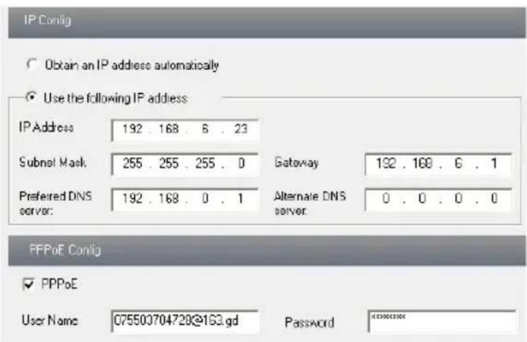
Fig 5-11 Wired Config
PPPoE configuration:
If you want to access through PPPoE, you need to check "PPPoE" and enter username and password for dial-up internet
PPPOE: User needs to manual input the user name and password for dial-up internet. Firstly, user needs to login IE clients, then enter into user name and password of PPPoE, save the setting and exit. Secondly, setup IP address change notice. Thirdly, connect with Modem, then the device will dial-up internet automatically.
- Press the "Save" button to save the settings.
5.4.3 NET Traversal Configuration
In this interface, user can access to network without dynamic domain name and port forwarding by enabling NET transit.
- Enter into “Network Configuration”→“NET traversal Config”. Refer to Fig 5-12:
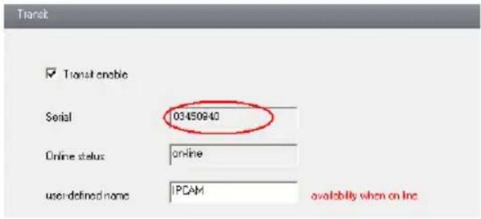
Fig 5-12 Transit
- Check "transit enable". Then save the setting.
- Input www.upnpicp.com in IE address; download and install Active X. Then a window shows up as Fig 5-13:
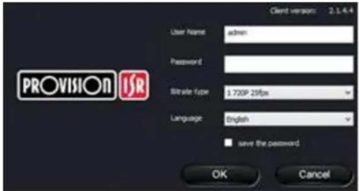
Fig 5-13 Login
- Input the only device ID of the IP-CAM or user-defined name. And then input user name and password.
Note: The default user name and password are “admin” and “123456” respectively.
5.4.4 Server Configuration
Enter into “Network Configuration”→“Server Config”. Please refer to Fig 5-14:
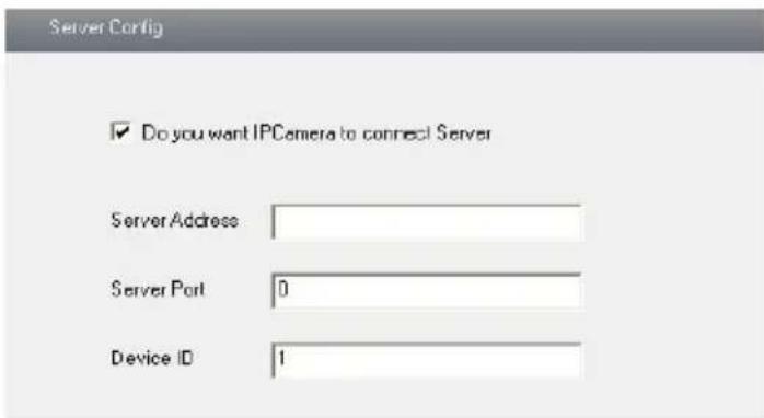
Fig 5-14 Server Configuration
- Check "Do you want IP Camera to connect Server."
- Check the IP address and port of the transfer media server in the ECMS/NVMS. Then enable the auto report in the ECMS/NVMS when adding a new device. Then input the remaining information of the device in the ECMS/NVMS. After that, the system will auto allot a device ID. Please check it in the ECMS/NVMS.
- Input the above-mentioned server IP, server port and device ID in the responding boxes. Click “save” button to save the settings.
5.4.5 IP Notify
- Enter into “Network Configuration”→“IP Notify” to see a tab as shown in Fig 5-15.
- If the “Enable notifying change of IP” is selected, when the IP address of the device is changed, a new IP address will be sent to the appointed mailbox automatically; If “FTP” is selected, when the IP address of the device was changed, a new IP address will be sent to FTP server.
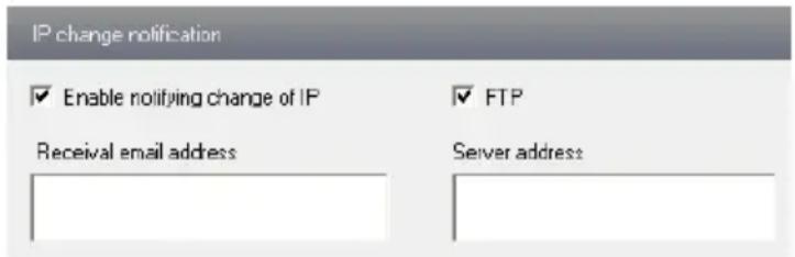
Fig 5-15 IP Notify Config
5.4.6 DDNS Configuration
- Domain name Registration (http://provision-ISR-dns.com) Note: DDNS is used to register for a hostname with DDNS username and password.
Provision ISR now allows you to use our mint DDNS server in order to create a virtual address for your DVR/NVR/IP-Camera on the internet. Each account is limited to 35 different addresses using your preferred domain name address instead of using IP addresses. Follow the steps below to register your DVR's name and to configure your DVR to use Provision ISR's Mint DDNS server.
(a) To register a domain with Provision-ISR DDNS server follow these steps:
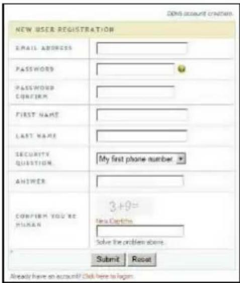
1) Visit our website: http://provision-isl-dns.com and register for a domain name by clicking "Registration"
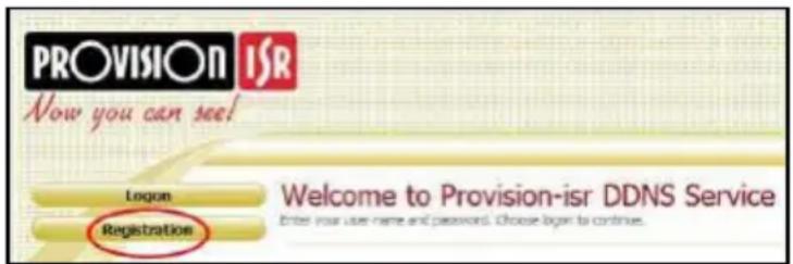
2) Fill in the registration form, then click "Submit"
3) Fill in the host name you want to apply for and press "Request Domain" (for example "home")
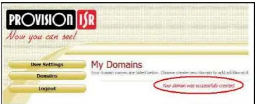
4) If there is no problem with the domain registration you will see the following message: "Your domain was successfully created."
![User Settings Domaine Logout Domain Name Creation Other a new domain name below. Domain name must start with [e.g., i.e.]. Connect end or start, but may contain a header and is not possible to access. Home prevision-irid-dhs.com Request Domain Type the same you want](/content/2026/05/1046794/images/e83c926f41f96650e8a7ddc45a560994088761b5c69e33c63d638738b59cd1a9.jpg)
If you do not see this message, the domain name you requested is already in use and you will be requested to provide an alternate domain name (please note: domain name is sometimes called host name).
You can create up to 35 domain records under a single account
5) The domain name is added at the beginning of
your DVR's address, for example the domain "home" will appear as home.provision-ISR-dns.com.
- Enter into "Network Configuration" "DDNS Configuration" tab as shown in Fig 5-16:
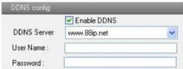
Fig 5-16 DDNS Config
Note: The steps to band a domain name for video surveillance server are as follows. Firstly, register a user name and a password to log on the website of service supplier, and then apply for a domain name online for the server. After that, users can visit the server through inputting the domain name at IE terminal.
2. Press the "Save" button to save the settings.
Please refer to the following table for parameters and instructions of DDNS configuration.
| Parameter | Meaning |
| DDNS server | Address of the website which provided by domain name supplier. The optional: www.dns2p.net, www.88ip.net, www.meibu.com, www.dyndns.com, www.no-ip.com, www.3322.org and mintdns type. |
| User name | Log in the website of domain name supplier |
| Password | Log in the website of domain name supplier |
1. Apply the Domain Name (Take dns2p for example)
(1) Register in the Web
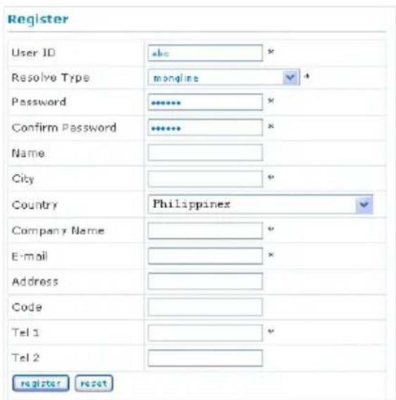
Register dialog box
Step 1: Fill in the blank of IE address with 'www.dns2p.com'.
Step 2: Click to enter the website.
Step 3: Click "New User" in the right of homepage to register. For example: User ID is 'abc', and password is '123456'. The register dialog display as below:
(2) Login
Step 1: Return to homepage after registering successfully.
Step 2: Click "Account Manager" on the right of homepage to login.
Step 3: Input the username and password with the information that you have registered.
Step 4: Click "Enter" key after filling in the textbox.
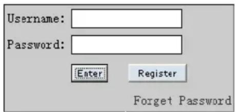
Log in
(3) Domain Setup
Step 1: Click "Domain Management" on the left to set the domain.

Domain setup
Step 2: Input the domain in the textbox. For example, you set ‘IP-CAMERA’ as the domain.
Step 3: Click "Submit" button, the system will pop up a dialog box to show that the domain is added successfully.
Note: Time of probationary period is one month. If user wants to use it continuatively after one month, please Step 4: click "Buy Now" in the right of homepage to pay for it.
Domain is set in ‘1. Apply the Domain Name’. According to the example above, the domain is ‘WWW. IP-CAMERA.dns2p.com’.
(2) USER ID
Username of registered which is set in ‘(1) Register in the Web’. According to the example above, user ID is ‘abc’.
(3) PASSWORD
Password is set in ‘(1) Register in the Web’. According to the example above, password is ‘123456’.
Note: If the connection fails, press the "INFO" button. Now the system will display: 'DDNS NONE'. Then you need to check network and information above and try again.
3. Application
Connect IP-CAMERA to the Network Client.
Step 1: After popping up the login interface, fill in "Server" textbox with ‘*.dns2p.com’ to visit the Network Client of the IP-CAMERA. The domain set in ‘(3) Domain Setup’. According to the example above, fill in "Server" textbox with 'IP-CAMERA.dns2p.com'.
Step 2: Click "save" button to save the above setting.
5.4.7 RTSP
Enter into "Network Configuration"→ "RTSP" interface as shown in Fig 5-17:
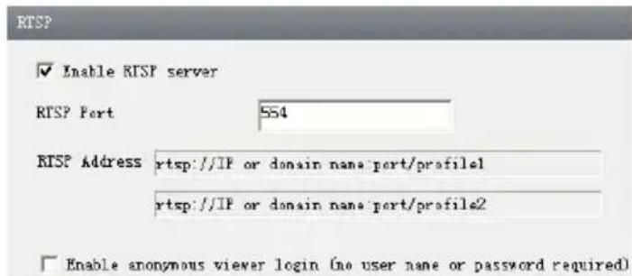
Fig 5-17 RTSP
- Select "Enable RTSP server."
- RTSP Port: Access Port of the streaming media. The default number is 554.
3.RTSP Address: The RTSP address you need to input in the media player. - Check "Enable anonymous viewer login...".
Application: This device supports VLC player. You should download the VLC player from the relevant website. Then choose "File" in the menu bar of the player and click "Open URL" order. Input the RTSP address in URL column and click "OK" button. Now, you can see the live image in the VLC player.
5.4.8 UPNP
Enter into “Network Configuration”→ “UPNP” interface as shown in Fig 5-18. Select “Enable UPNP” and then input friendly name.
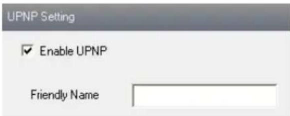
Fig 5-18 UPNP
Enable UPNP
Double-click the "My Network Places" icon on the desktop in PC and select "Show
icons for networked UPnP devices" in the "Network Tasks" list box. Then a information window will pop up. Click "YES" button to see a "Windows Components Wizard" dialog box pop up as shown below. Then press "Next" to continue. After finished the installation of configuring components, the UPnP icons will display. Users can double-click certain icon to connect the remote surveillance login interface through IE.
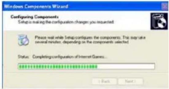
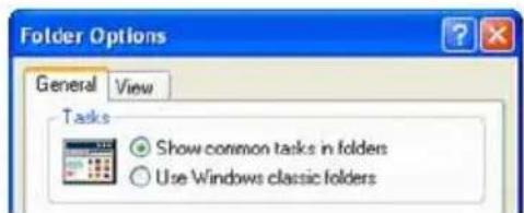
If “Show icons for networked UPnP devices” can’t display in the “Network Tasks” list box, please follow the below operation:
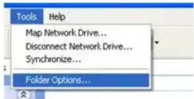
- Click "Tools"--"Folder options"
- Check the “Show common tasks in folders” in the “Tasks” check box, UPnP icon will display.
5.4.9 Mail Setting
Enter into “Network Configuration” → “Mail Setting” interface. Please refer to Fig 5-19.
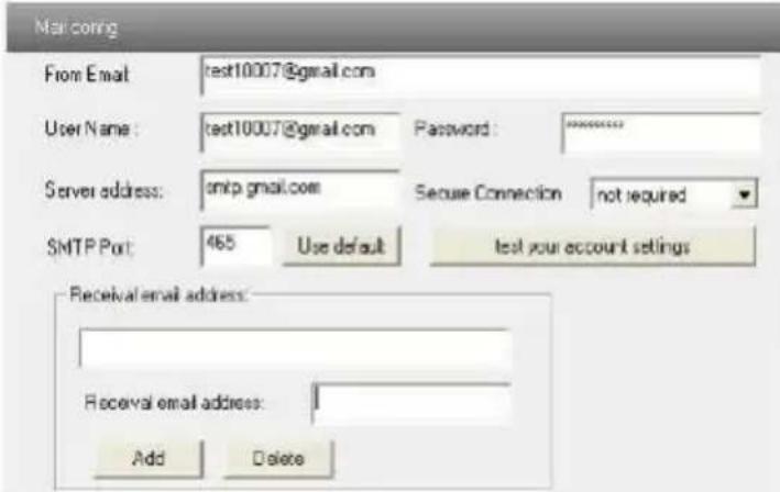
Fig 5-19 Mail Setting
- From Email: sender's e-mail address
- User name and password: sender's user name and password
-
Server address: SMTP name of sender
-
Select the secure connection type at the Secure Connection pull down list according to user' actual needs
- Receival email address list: add email address into the list
- Receival email address: receiver's e-mail address
- After all parameters setup, user can click “Test your account settings”. If email sent successful, a “Test Successful” window will pop up, if not, users can try other email addresses or check the setting.
Notice: If user change the static IP into PPPoE and select mailbox, there will be an e-mail sent to users' mail box for notify a new IP address.
5.4.10 FTP
Enter into Network Configuration→FTP interface; please refer to Fig 5-20:
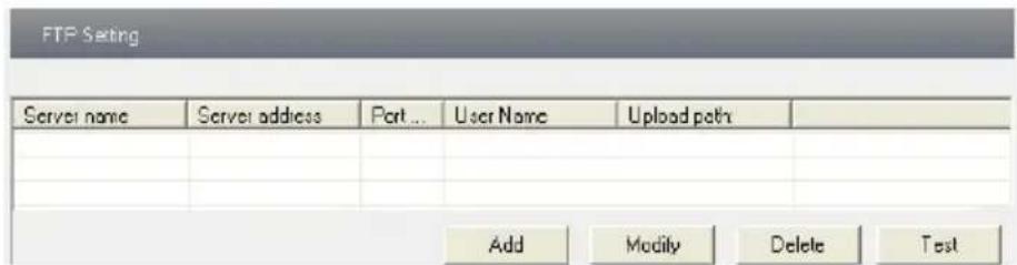
Fig 5-20 FTP Setting
- Add: Click Add button to input FTP server's server name, address, port number, user name, password, and upload path, click OK to confirm the setting. Refer to Fig 5-21:
- Modify : User can click this button to change some information of the FTP server
- Delete : Select certain FTP account; Click this button to delete this account
- Test : Select certain FTP account; Click this button to test its valid or not.
Please refer to the following table for parameters and instructions of FTP configuration.
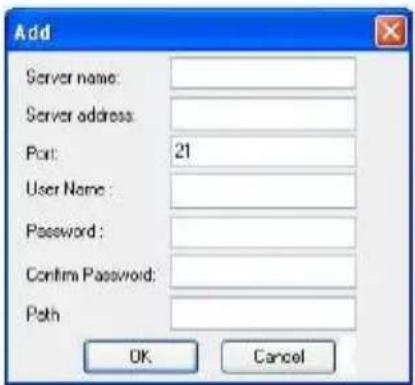
Fig 5-21 Add
| Parameter | Meaning |
| Server name | The name of the FTP server |
| Server address | The address of the FTP server |
| Port | The port number of the FTP server |
| User name | The user name of the FTP server |
| Password | The password of the FTP server |
| Path | The save path for FTP files |
5.5 Advanced Configuration
Advanced configuration includes five submenus: User Configuration, Onvif Configuration, Security Configuration, Configure Backup & Restore, Reboot and
Upgrade.
5.5.1 User Configuration
Enter into "User Configuration" interface. Refer to Fig 5-22:
Add user:
- Clicking "Add" button pops up "Add user" dialog box. Please refer to Fig 5-23:
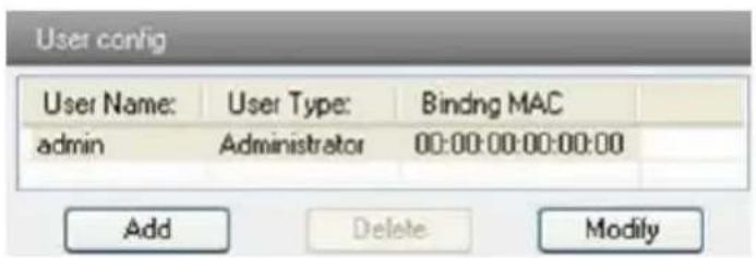
Fig 5-22 User Configuration
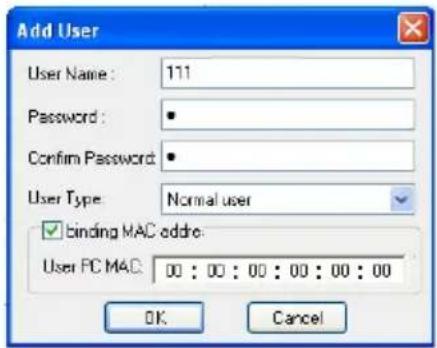
Fig 5-23 Add User
Note: After bind physical address to the IP-CAM, user can access the device on this PC in network only. If the MAC address was “00:00:00:00:00:00” which means it can be connected to any computers.
- Input user name in "User Name" textbox (only letters).
- Input characters in "Password" and "Confirm Password" textbox (letters or numbers).
- Input the MAC address of the PC in "Binding MAC address" textbox.
- Click "OK" button and then the new added user will display in the user list.
Modify user:
- Select the user which needs to modify password and physical address in the user configuration list box.
- Clicking "Modify" button will pop up "Modify user" dialog box as shown below.
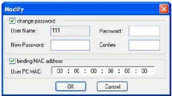
Fig 5-24 Modify User
- Input original password of this user in the "password" text box.
- Input new password in the "New password" and "Confirmation" text box.
- Input computer's physical address which is used to access the server in the "User PC
MAC" text box.
- Click “OK” button to modify user's password and binding MAC address successfully.
Delete user:
- Select the user which needs to delete in the user configuration list box.
- Clicking “Delete” button will pop up a confirm dialog box. Then click “OK” to delete the user.
Note: The default super administrator cannot be deleted.
| Parameter | Meaning |
| User Name | User name to operate the logon client end |
| User Type | Type of users, normal user, advanced user and super administrator |
| Binding MAC address | The MAC addresses of user access the server which should setup according to actual MAC address of server. |
| Password | Password to log in the client terminal |
| Confirm Password | Password to log in the client terminal |
5.5.2 Security Configuration
Enter into Advanced Configuration→Security Configuration to see a tab shown in Fig 5-25:
Check “Enable IP address” check box, select “Deny the following IP address”, input IP address in the IP address list box and click “Add” button. Then this IP address will display in the list box; the operation step of “Allow the following IP address” is the same with “Deny the following IP address”
Select the IP address which needs to be deleted from the IP address list box and click “delete” button to delete that IP address.
Check “Enable MAC address” check box, select “Deny the following IP address”, input MAC address in the MAC address list box and click “Add” button. Then this MAC address will display in the list box; the operation step of “Allow the following MAC address” is the same with “Deny the following IP address”.
- Select the MAC address which needs to be deleted from the MAC address list box and click "delete" button to delete that MAC address.
- Click "save" button to save the above setting.
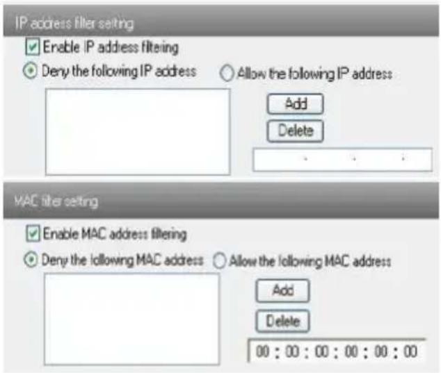
Fig 5-25 Security Configuration
5.5.3 Configure Backup & Restore
Enter into Advanced configuration→Configure Backup & Restore Interface. to Fig 5-26.
- Import & Export Configuration:
User can import or export the setting information from PC or to device.
- Click "Browse" to select save path for import or export information on PC.
- User can import or export all setting information to PC, but those two settings “user configuration” and “network configuration” are exceptional.
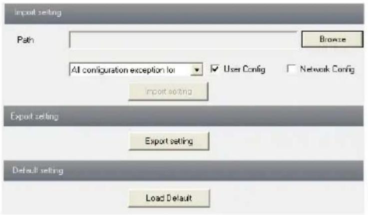
Fig 5-26 Backup and Restore Configuration
- Default Configuration
Click "Load default" button to restore all system settings to default status.
5.5.4 Reboot Device
Enter into Advanced configuration—Reboot device to see a interface as shown in Fig 5-27:
Click "Reboot device" button to reboot the device.
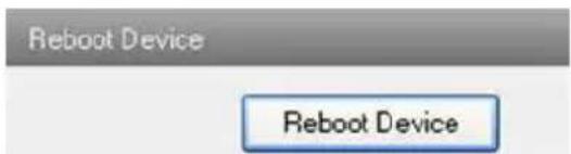
Fig 5-27 Reboot device interface
5.5.5 Upgrade
Enter into Advanced Configuration—Upgrade interface shown as Fig 5-28:
- Click "Browse" button to select the save path of the upgrade file
- Click "Upgrade server firmware" button to start upgrading the application program
- The device will restart automatically
- After you successfully update the software, click "OK" button to close IE and then re-open IE to connect IP-Cam.
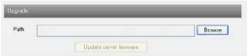
Fig 5-28 Upgrade
Notice: User can't disconnect to PC or close the IP-CAM during upgrade.
6 Mobile Surveillance
This IP-CAM supports mobile surveillance by phones with Windows mobile, iPhone, Android and Blackberry OS. Please check the operation system version of mobile before use; and connect the IP-CAM to Internet.
6.1 Network Configuration
- Access device via LAN
Step 1: Connect device via wireless router. Then checkmark DHCP both in router and device to automatically acquire IP address or enter the IP address manually.
Step 2: Use WIFI function in your mobile phone to connect the wireless router.
Note: Make sure your phone network and device network are in the same network segment on LAN.
Step 3: Add the IP address and port in the mobile phone surveillance client.
- Access device via 3G network
Step 1: Set the device network. Please enter Main Menu→Setup→Network tab.
If you use PPPoE to connect device, please enable PPPoE and input username and password received from you ISP in network tab. Then click “Apply”. You can enter Main Menu→Information→Network tab to see the IP address. If you want to utilize dynamic domain name, please apply for a domain name in a DNS server supported by the device.
If you have a static WAN IP address, please enter Main Menu→Setup→Network tab to input your IP address, gateway and port.
If you use LAN IP address, please enter Main Menu→Setup→Network tab to input your IP address, gateway and port and then forward IP address and port number in virtual server setup of the router or virtual server(If you has enabled the UPnP function in both the device and router, you can skip this step). Port forwarding setting may be different in different routers and servers. Please refer to the router's manual for details. After you forward your LAN IP address and port, please check the WAN IP address in the router or server.
Step 2: Add the WAN IP address or domain name in mobile phone surveillance client.
6.2 By Phones with iPhone OS
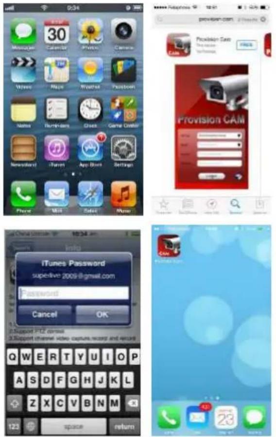
• Install through Iphone.
Step 1: Open App Store software as shown in the figure on the left.
Step2: Search “Provision Cam” and click “Free” button as shown in the figure on the right.
Step 3: Click "Install App" button as shown in the figure on the left.
Step 4: Input iTunes Store password and then click "OK". The software will be installed automatically.
• Install Software through PC
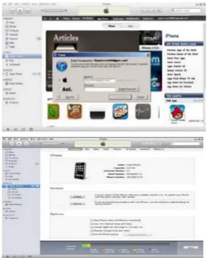
Step 1: Install iTunes store in PC and then login.
Step 2: Connect iPhone and PC.
Step 3: Search and select “Provision Cam”.
Step 4: Click "Download" button.
Step 5: Input username and password.
Step 6: Synchronously apply "Provision Cam" software to iPhone/iPad.
- "Provision Cam" Instruction
1. Login
Step 1: Choose network type. There are two network connection ways: 3G/3G +WIFI, enhanced video quality. This network supports main stream and sub stream. The real-time image will be displayed by using sub stream. 3G, normal video quality compared to the former network type.
Step 2: Input server, account and password.
Server: WAN IP address (or domain name) plus HTTP port of the device. For example: 210.21.183:89 or 123.dvrdydns.com:89.
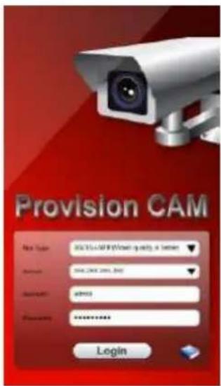
Note: The default http port of the device is 80. If modified, use the modified port. Account and Password: The login account and password of the device. The default account is admin and the default password is 123456.
Step 3: Click 【Login】 button to access the device.
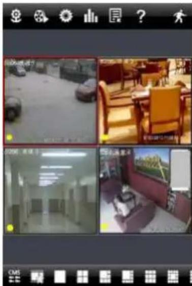
2. Main Interface
There are many buttons in the main interface, such as, screen mode, favorite channel, snap, record, open/close audio, talk, PTZ., etc.

: Image view button. The pictures snapped in the live will be checked by clicking this button.

: Playback button. Click this button to enter into playback interface.

: Settings button. Click this button to set local configuration (Some can also support remote configuration).
natural_image
Four-panel photo collage showing indoor scenes with vehicles and furniture, no visible text or symbols
: Information button. Click this button to check lots of information including local information, device information, network information, etc.


: Server list button. Click this button to add server list.
Help button. Help you know about the use of this software quickly.
: CMS button. Make you preview the live image of multi-devices.

: Log off button. Click this button to return to the login interface.

: Screen mode button. You can choose 1, 4, 6, 8, 9,
13 or 16 screen display mode.

: Favorite channel display button. If you save your favorite channel in the favorite er list, clicking this button will directly play all favorite channels you have saved.

: Snap button. Choose the channel and click this button to capture the channel name.

: Local record button. Choose the channel and click this button to start recording.

: Open/Close audio. Choose the channel and click this button to open/close the number of this channel.

: Open/Close talk. Click this button to pop up the servers which support talk ion. Select the device to start talking.

: Set video parameter button. Select the channel and click this button to set the parameters including brightness, hue, saturation and contrast.

: PTZ button. Click this button to pop up PTZ control panel.

: Choose bitrate priority or quality priority according to
Channel indicator instruction:

: Video loss

: Schedule recording

: Others

: Sensor alarm

: Motion alarm

: Motion /sensor alarm based recording or manual recording
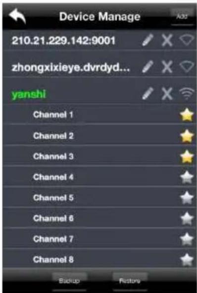
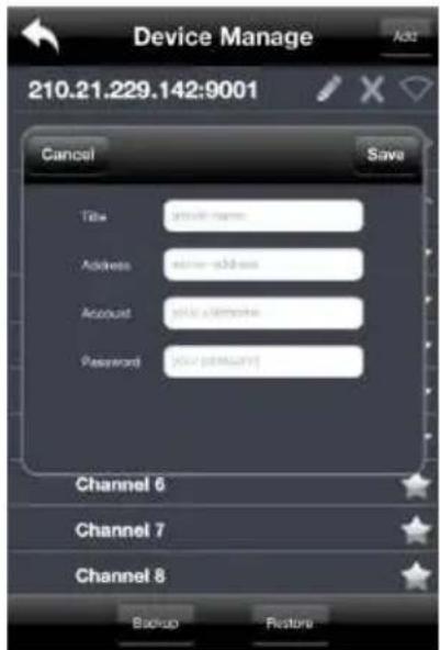
3. Server list
Click button to pop up the following picture.
➢ Add device: Click “Add” button in the top right corner to pop up a dialog box as shown in the following left picture. Input the relative information of the device and click “Save” button.
➢ Delete device: Click

button behind the device name to delete this device.
➢ Edit device: Click 📋 button behind the device name to edit the information of this device.
➢ Backup & restore: It is recommended to click “Backup” button to reserve the information of all devices. Then you can click “Restore” button to restore all device information after you re-install the client or delete the device uncarefully.
indicates the device has been connected;
indicates the device is connecting;
indicates the device is not connected.
4. Live Preview
Once you access the device, the system will automatically display the screen mode in accordance with the channel number of the device
Note: The maximum number of channels which can be connected are nine after login.
Click "Screen mode" button to select channel as shown in Fig 1.
When there is video playing in a screen, you can switch the channel by long pressing the screen as shown in Fig 2.
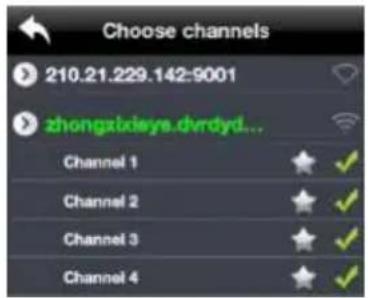
When no video is playing in a screen, click this screen to choose channel as shown in Fig 3.
When the single channel is playing, you can zoom in/out the image by swiping you finger up and down as shown in Fig 4.
When the single channel is playing, the channel can be switched by swiping your finger left or right as shown in Fig 5.
When multi channels are playing, drag one channel screen to the other channel screen. This will make these two channels change the position of each other.
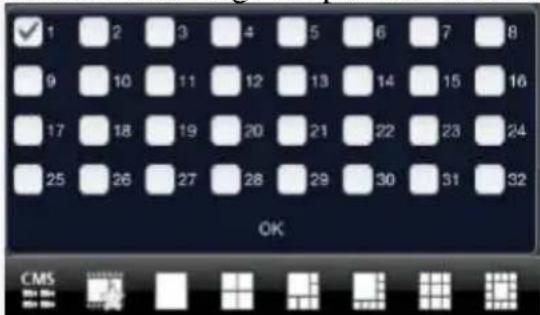
Fig 1
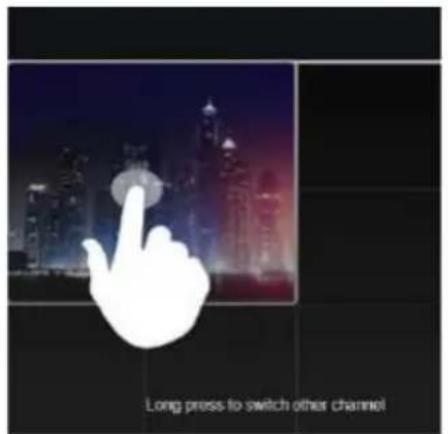
Fig 2
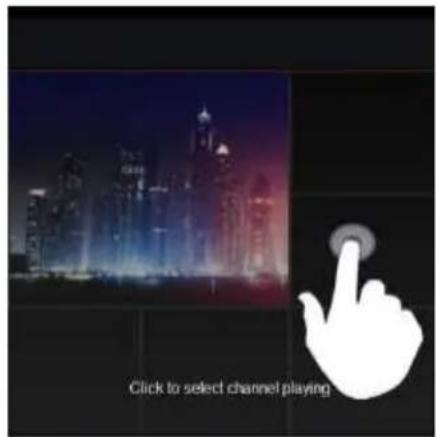
Fig 3

Fig 4
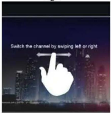
Fig 5
5. CMS Function
This function makes multi-device managements and preview come true.
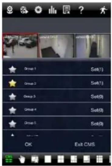
Step 1: Click a enable CMS function. When this icon turns green, it means this function is enabled.
Step 2: Click Set(0) to choose channel as shown in the
right picture. After you choose the channel, click "ok", the system will display the related image automatically.
- If channels have been added into the group, you can see the images by clicking the group name.
- On viewing the group channel images, click 📋 button and select channels to check other channel images.
- Click “Exit CMS” to exit CMS mode and return to the main interface of the device.
6. Favorite Channel/Group
There are two kinds of favorite channels: favorite channels of the device and favorite group of CMS.
● Favorite channels of the device
Step 1: Click ☐ to enter into device management list. Click the device name to extend channel. Enlighten the channels to save favorite channels as shown in the following picture on the left.
Step 2: Return to the main interface and click button to play the favorite channels.
- Favorite groups of CMS
Enable CMS function and enlighten the group to save the favorite groups as shown in the following picture on the right.
Then click button to play. Only one favorite group can be collected.

: Color means the channel or group has been
collected. Grey means the channel or group isn't collected.
7. Playback Interface
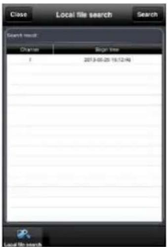
Click “Playback” button to enter the playback interface. Then click “Search” button to search the file. To play the record by click this file name.
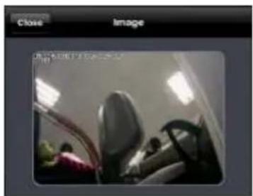
8. Image View
Click button to view the captured pictures.
9. Settings Interface
In this interface, you can configure the local settings.
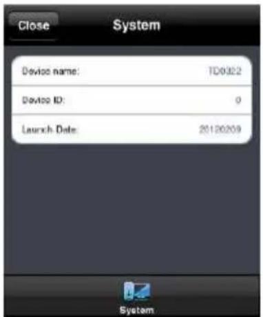
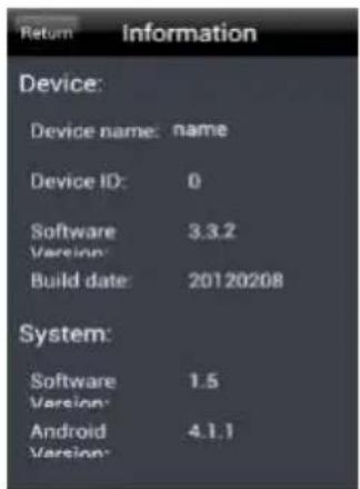
10. Information Interface
In this interface, you can view system information.
natural_image
Interior view of a vehicle showing rearview mirror and dashboard (no visible text or symbols)
6.3 By Phones with Android
Software Installation
Step 1: Run “Play Store” (or Google market) program.
Step 2: Search "Provision Cam".
Step 3: Press "Install" button.
Step 4: Install the software subject to the notes. Once the downloading is done, the software will install automatically
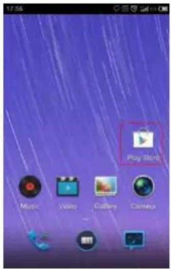
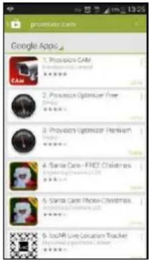
Login Menu
Step 1: Configure the network of your device and mobile phone.
Step 2: Input the WAN IP address/domain name and port of your device in the sever column. The port should be HTTP port of your device. The default http port of the device is 80. If you have changed your http port, please enter the new port here. For example: 210.21.228.183:89 or 123.dvrdydns.com:89.
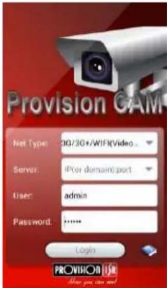
Step 3: Input the account and password of your device. The default account name is admin and the default password is 123456.
Step 4: Check "Remember Server" to save the setting. When you login next time, you can click button to select this server for quick access.
 | PTZ | |
 | Snap | |
 | Record | |
 | Talk | |
 | Enable/disable audio | |
 | Hide | |
 | Playing favorite channel |
Main Menu
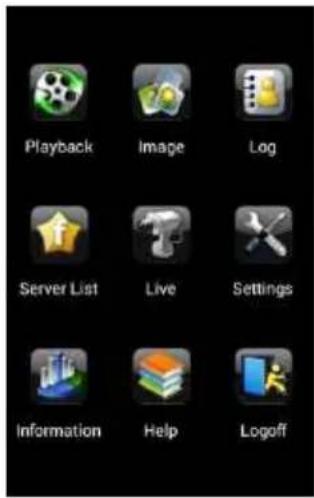
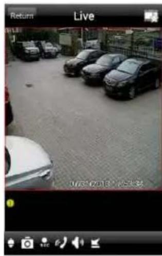
Live View
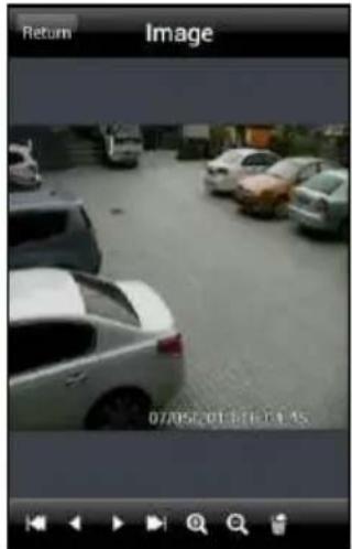
 | The first picture | |
 | The previous picture | |
 | Next picture | |
 | The last picture | |
 | Zoom in | |
 | Zoom out | |
| Delete |

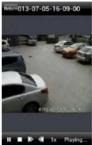
Record Playback:
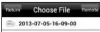
Click “Playback” in the main menu interface to enter playback interface. Then choose the channel you want to playback. This will take you to see the record file. Click this file to play.
natural_image
Black-and-white photo of a parking lot with several cars parked in the background (no visible text or symbols)
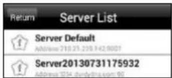
Server List:
In the main menu interface, click "Server list" to see the above picture on the left hand.
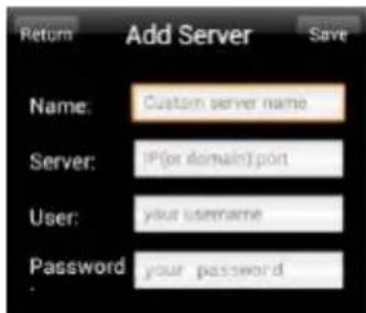
Add Server: Click button to pop up a window as shown in the above picture on the right hand. Enter the name, server, user and password of the device you want to add. Then click "Save" button to save the server. When you log in next time, you can choose and quickly access this server by clicking the little triangle button in the server column.
Modify Server: Click button to modify the server information. Delete Server: Click button to delete the server information.
Settings:
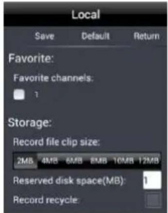
In the main menu interface, click "Settings" to enter the settings interface where you can configure local settings. Click "Local" to enter local settings interface. In this interface, you can set favorite channel and storage.
Favorite Channel:
Check the favorite channels and click "Save" button to save these channels. Then go into live interface and click button to play these favorite channels.
Storage: Setup the relevant parameters of mobile video.
Information View: view the DVR/NVR basic information as shown in the picture on the right.
7 Use method for IP-TOOL
Updating through IP-Tool
Note: Do not cut off power supply and internet when updating; If the device is unable to start because of the failure of upgrade, it needs to retrofit.
First, acquire the IP-Tool from the supplier and then double click the IP-Tool icon

to run this software. Then the device can be searched; if the device can't be searched, please check whether the PC and the device connect to the network or not.
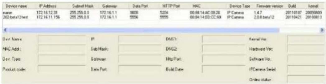
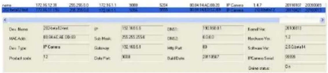
Click the device to check its detail information as shown below:
◆ Network Setup
When upgrading the software and kernel, the IP address of PC and device should be at the same network segment. If the network segment is different, user should change the IP address by right clicking the device and then select “network setup”.
Modify IP address dialog box will appear as follows:
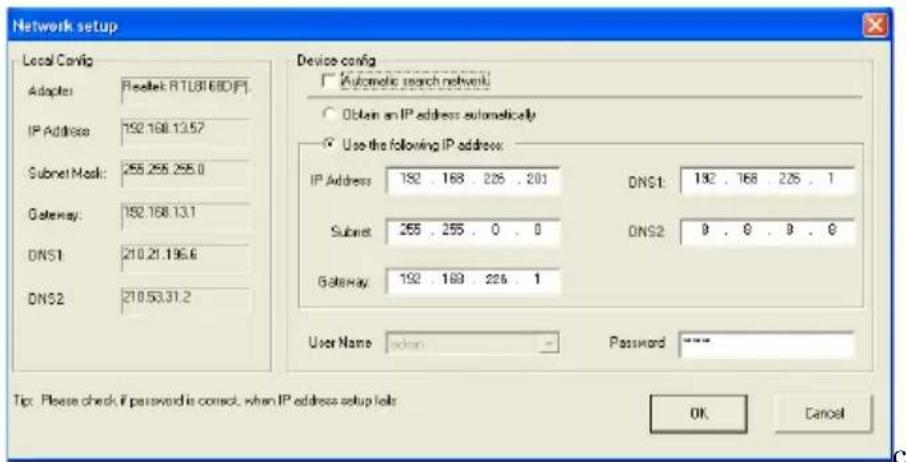
Modify IP address and click OK button to exit the dialog box, IP-Tool will display the new IP address.
◆ Upgrading Software
Select the device and right click to choose “Update software” menu. Input the username and password. Then click “browse” button to choose the upgrade software. Finally, click “Update software” to start upgrading. When upgrading, please do not disconnect PC and the device and make sure the power is on.
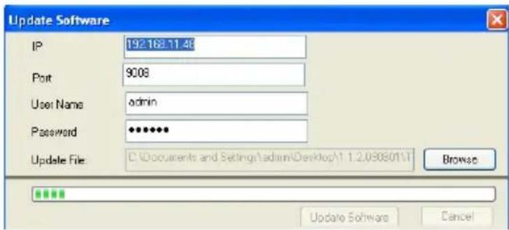
After finishing upgrading, a message box will pop up as below:
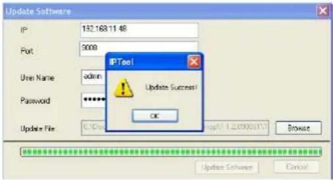
Click OK button to exit the update dialog box and then the device will restart automatically.
◆ Upgrading Kernel
Select the device and right click it to select "Update kernel".
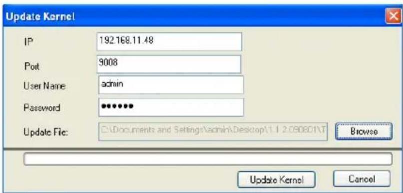
Enter into Kernel upgrade dialog box, input user name and password, click “Browse” to select the Update file (mboot8180-8180) and click “Update” button to start updating. When upgrading, please do not disconnect PC to device and make sure the power is on. The update progress bar will display as below:
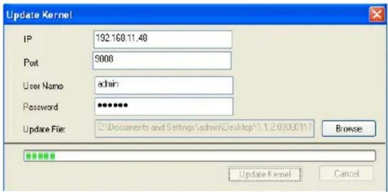
After finishing upgrading, a message box will pop up. After a while, the device will restart automatically.
Modifying Device Name
Right click the device you want to modify and select “Modify Device Name” from the drop-down list. This will bring up a window for changing device name. Input new device name and click “OK” button to save the setting.
8Q & A
Q: How to find my password if I forget it?
A: Reset all settings by IP-Tool or contact your dealer.
Default IP: 192.168.226.201
User name: admin
Password: 123456
Q: Fail to connect devices through IE browser, why?
A: Network doesn't connect well. Please check the connection and make sure it connected well.
B: IP is not available. Reset the valid IP.
C: Web port number has been revised: contact administrator to get the correct port number.
D: Exclude the above reasons. Recover default setting by jointing the default line and GND line.
Note: default IP: 192.168.226.201, mask number: 255.255.255.0
Q: IP tool cannot search devices, why?
A: It may be caused by the anti-virus software in your computer. Please exit it and try to search device again.
Q: IE cannot download ActiveX control. How can I do?
a. IE browser blocks ActiveX. Please do setup following below.
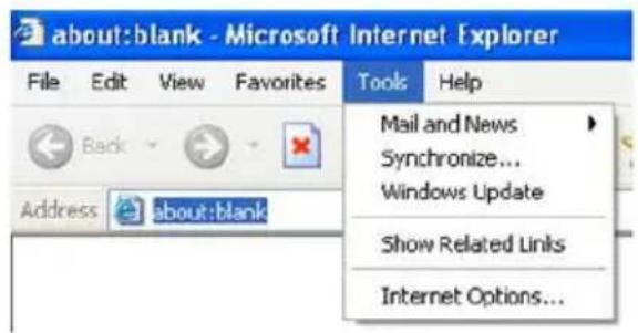
① Open IE browser. Click Tools----Internet Options....
② select Security----Custom Level....Refer to Fig 4-1
③ Enable all the sub options under “ActiveX controls and plug-ins”. Refer to Fig 4-2
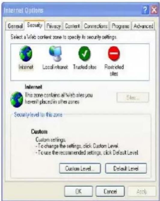
Fig 4-1
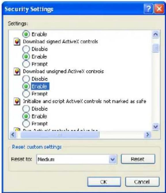
Fig 4-2
④ then click ok to finish setup.
b. Other plug-ins or anti-virus blocks ActiveX. Please uninstall or close them.
Q: No sound can be heard, why?
A: Without connect audio input device. Please connect and try again.
B: Without enable audio function at the corresponding channel. Please check AUDIO item to enable this function.
Q: Why doesn't the device connect to wireless?
A: Check the statues of wireless router. Please make sure the router is open
B: Check the router and the device port. Please make the router setup is matched with device port.
9 Specification
| Model | I3-390IP04 |
| Image Sensor | Sony Exmor IMX138 1/3" CMOS |
| Effective Pixels | 1280x720 |
| Electronic Shutter | 1/25s ~ 1/100000s |
| Day & Night | ICR |
| Min. Illumination | 0lux (IR ON) |
| Audio compression | G711A |
| Communication | One Way Audio |
| Image Settings | AWB, AES, AGC Adjustable |
| Exposure Mode (Auto / Manual) | |
| BLC, HLC Adjustable | |
| Sharpness, Saturation, Brightness & Contrast Adjustable | |
| WDR Range | Digital WDR |
| Noise Reduction | 3D-DNR |
| Image Orientation | Mirror/Flip |
| Privacy Zone | Yes |
| Motion Detection | Yes |
| Video Compression | H.264 |
| Resolution | 720P (1280x720), VGA (640x480), QVGA (320x240) |
| Multi-stream | 1280x720 (1~30fps) / 640x480 (1~30fps) / 320x240 (1~30fps) |
| Bit rate | 64Kbps ~ 8Mbps |
| Encode Mode | VBR/CBR |
| Image Quality | Five levels under VBR; Free adjustment under CBR |
| IR Distance | 30m |
| Lens | 4mm |
| Iris | Fixed Iris |
| Lens Mount | Φ14 mount |
| Water-proof | IP66 |
| Bracket | 3-Axis Wall Bracket |
| Dimensions | Φ87mm×219mm |
| Weight(gross) | 635g |
| Network | RJ45 (+PoE) |
| Power | DC Socket |
| Analog Video Output | CVBS (BNCx1) |
| Mic Connectivity | 1Ch Input |
| SD Card | No |
| RS485 | No |
| Alarm | No |
| Remote Monitoring | IE Browsing, CMS 2.0 Control Software, Provision CAM Mobile App for iOS &Android |
| User Access | Supports simultaneous monitoring for up to 4 users with multi-stream real time transmission |
| Network Protocol | TCP/IP, UDP, DHCP, NTP, RTSP, PPPoE, DDNS, SMTP, FTP |
| ONVIF | Yes |
| Ethernet | 100Mbps |
| PoE | Yes |
| Power Supply | DC12V/PoE |
Notes:

Now you can see!
- IP Series
- PROVISION-ISR
- I3-380IP04
- User Manual
- Before use this product
- Table of Contents
- Introduction....1
- Installation 2
- IE Remote Access....3
- Remote Preview....7
- Remote Live Surveillance....10
- Mobile Surveillance 29
- Use method for IP-TOOL....39
- Q & A 42
- Specification 44
- Introduction
- Summarization
- Check Package Content
- Connection
- Installation
- Install IP-CAM to Ethernet Network
- CMS and IP-Tool Installation
- IE Remote Access
- LAN
- Access through IP-Tool
- Directly Access through IE
- WAN
- Access through router or virtual server
- Remote Preview
- The Remote Preview Interface
- Record Playback
- Right-click Function
- Snap Pictures
- Remote Live Surveillance
- System Configuration
- Basic Information
- Setting steps:
- Date & Time Configuration
- Video Configuration
- Camera Configuration
- Video Stream
- Time Stamp
- Video Mask
- Alarm Configuration
- Motion Detection Area
- Motion Detection Trigger
- Motion Detection Schedule
- Week schedule
- Day schedule
- Network Configuration
- Port
- Wired
- NET Traversal Configuration
- Server Configuration
- IP Notify
- DDNS Configuration
- Press the "Save" button to save the settings.
- Apply the Domain Name (Take dns2p for example)
- Register in the Web
- Login
- Domain Setup
- USER ID
- PASSWORD
- Application
- RTSP
- UPNP
- Enable UPNP
- Mail Setting
- FTP
- Advanced Configuration
- User Configuration
- Add user:
- Modify user:
- Delete user:
- Security Configuration
- Configure Backup & Restore
- - Import & Export Configuration:
- - Default Configuration
- Reboot Device
- Upgrade
- Mobile Surveillance
- Network Configuration
- - Access device via LAN
- - Access device via 3G network
- By Phones with iPhone OS
- • Install Software through PC
- - "Provision Cam" Instruction
- Login
- Main Interface
- Server list
- Live Preview
- CMS Function
- Favorite Channel/Group
- ● Favorite channels of the device
- - Favorite groups of CMS
- Playback Interface
- Image View
- Settings Interface
- Information Interface
- By Phones with Android
- Software Installation
- Login Menu
- Record Playback:
- Server List:
- Settings:
- Favorite Channel:
- Use method for IP-TOOL
- Updating through IP-Tool
- ◆ Network Setup
- ◆ Upgrading Software
- ◆ Upgrading Kernel
- Modifying Device Name
- 8Q & A
- Notes:
Brand : Provision-ISR
Model : I3-380IP04
Category : Security Camera