
Wireless B Router 523233 - Router Intellinet - Free user manual and instructions
Find the device manual for free Wireless B Router 523233 Intellinet in PDF.


| Brand | Intellinet |
| Model | 523233 |
| Product Type | Wireless B Router (802.11b) |
| Wireless Standard | IEEE 802.11b |
| Maximum Wireless Speed | 11 Mbps |
| Frequency Band | 2.4 GHz |
| Number of LAN Ports | 4 (10/100 Mbps) |
| Number of WAN Ports | 1 (10/100 Mbps) |
| Antenna Type | Internal / External (fixed) |
| Security | WEP, WPA, WPA2 |
| Firewall | NAT, SPI, DoS prevention |
| DHCP Server | Built-in |
| Power Supply | 5V DC, 1A |
| Dimensions (W x D x H) | 7.0 x 5.0 x 1.5 inches |
| Weight | 0.5 lbs |
| Operating Temperature | 0°C to 40°C |
| Storage Temperature | -20°C to 70°C |
| Humidity | 10% to 85% non-condensing |
| LED Indicators | Power, WAN, LAN (4), WLAN |
| Reset Button | Yes (pinhole) |
| Configuration | Web-based interface |
| Management | Remote access, firmware upgrade |
| Package Contents | Router, power adapter, Ethernet cable, quick start guide |
| Certifications | FCC, CE |
| Cleaning Instructions | Wipe with dry cloth, keep away from liquids |
| Repairability | Non-user serviceable; contact support |
Frequently Asked Questions - Wireless B Router 523233 Intellinet
User questions about Wireless B Router 523233 Intellinet
0 question about this device. Answer the ones you know or ask your own.
Ask a new question about this device
Download the instructions for your Router in PDF format for free! Find your manual Wireless B Router 523233 - Intellinet and take your electronic device back in hand. On this page are published all the documents necessary for the use of your device. Wireless B Router 523233 by Intellinet.
USER MANUAL Wireless B Router 523233 Intellinet
802.11b Wireless Router User Manual
FCC Certifications

This equipment has been tested and found to comply with the limits for a Class B digital device, pursuant to Part 15 of the FCC Rules. The equipment version marketed in US is restricted to usage of the dianana 1-11 only. These limits are designed to provide reasonable protection against harmful interference in a residential installation. This equipment generates, uses and can reliable radio frequency energy and if not installed and used in accordance with the instructions, may cause harmful interference to radio communications. However, there is no guarantee that interference will not occur in a particular installation. If this equipment is necessary, it is not suitable for any harmful interference to radio or television reception, which can be determined by suring the equipment eff and on. The user is encouraged to try to correct the interference by one of the following measures:
- Reorient or relocate the receiving antenna.
- Increase the separation between the equipment and receiver.
- Connect the equipment into an outlet on a circuit different from that to which the receiver is
connected. - Consult the dealer or an experienced radio-TV technician for help.
This device complies with Part 15 of the FCC Rules. Operation is subject to the following two conditions: (1) This device may not cause harmful interference, and (2) this device must accept any interference received, including interference that may cause undesired operation.
FCC Caution: Any changes or modifications not expressly approved by the party responsible for compliance could void the user's authority to operate this equipment.
IMPORTANT NOTE:
FCC Radiation Exposure Statement
This equipment complies with FCC radiation exposure limits set forth for an uncontrolled environment. End users must follow the specific operating instructions for satisfying RF exposure compliance.
This transmitter must not be co-located or operating in conjunction with any other antenna or transmitter.
The equipment version marketed in US is restricted to usage of the channels 1-11 only
CE Mark Warning
CE0560①
This equipment complies with the requirements relating to electromagnetic compatibility. EN55022 class B for ITE, the essential protection requirement of Council Directive 89/336/EEC on the approximation of the laws of the Member States relating to electromagnetic compatibility.
Company has an ongoing policy of upgrading its products and it may be possible that information in this document is not up-to-date. Please check with your local distributors for the latest information. No part of this document can be copied or reproduced in any form without written consent from the company.
Trademarks:
All trade names and trademarks are the properties of their respective companies.
Copyright © 2003, All Rights Reserved.
Document Version: 2.0
Table of Contents
Unpacking Information 1
Introduction To Wireless Router 2
General Description 2
Key Features 3
The Front Panel 4
System LEDs 4
Port LEDs (WAN)
Port LEDs (LAN) 4
Port LEDs (Wireless) 5
Factory Setting button 5
The Rear Panel 6
Power Connection 6
Placement (Optional) 6
Installing And Using Wireless Router 8
Network configuration setup 8
Computer configuration setup 9
Wireless Router configuration setup 14
Status 15
Wireless 17
TCP/IP Setting 24
Firewall Configuration 29
Syslog 33
Statistics 34
Upgrade Firmware 34
Save and Reload 35
Password 35
Product Specifications 36
Appendix 37
Unpacking Information
Thank you for purchasing the Wireless Router. Before you start, please check all the
contents of this package.
The product package should include the following:

natural_image
Exploded view diagram of a wireless router with internal components and a CD (no text or labels)- One Wireless Router
- One power adapter
- One User Manual (CD)
- One QIG
- Stand and Screws (Optional)
Introduction To Wireless Router
General Description
The Wireless Router built-in with 4-port 10/100Mbps Fast Ethernet Switch is the latest generation of Wireless router product for Home/Office and SOHO users who are thirsting high speed Internet access. This full-feature and self-contained compact Wireless Router will be fully for broadband access in both of LAN and Wireless environment. This device has been specifically designed to provide LAN and Wireless users the most cost-effective method with multiple accesses to the Internet at the cost of a single public IP address (IP Sharing) and enjoy the true Plug-and-Play installation. Moreover, the built-in 4-port 10/100Mbps switch lets users plug the network cable into the device without buying additional switch.
This device is also an Access Point. It has a built-in wireless LAN. Users can connect to Internet using wireless network interfaces anywhere within the range of its radio transmission. It's idea for SOHO users who require instant and convenient access to Internet without the restriction of connecting cables.
The friendly WEB-based graphics interface for setup makes any inexperienced users soon enter plug-and-play operation. Embedded DHCP server simplified IP address management and no MIS people needed for daily technical services. What is more, NAT/firewall is also implemented on this compact Router Box for protecting whole LAN from outside attack.
Key Features
The switch provides the following key features:
- Complies with 10BASE-T specifications of IEEE802.3 standard
- Complies with 100BASE-TX specifications of IEEE802.3u standard
- Complies with IEEE602.3x full duplex operation and flow control
- 4 * RJ-45 ports for 100BASE-TX and 10BASE-T connectivity on LAN side
- 1 * WAN port on WAN side
- Friendly GUI offers painless setup and management!
- LAN/WAN management via WEB-Based management interface
- Supports DHCP client/server function
- Supports N-Way Auto-Negotiation on each LAN and WAN port
- Supports PPPoE protocol
- Supports NAT/NAPT function
- Supports Port, IP and MAC filtering, Port Forwarding and Virtual DMZ (Firewall), WEP and WPA (Wireless)
- Supports extensive LED indicators for network diagnostics
- External power adapter
- FCC CLASS B, CE
- Built-in 11Mbps IEEE802.11b wireless LAN Access Point
An instant LAN with an integrated 4 ports 10/100Mbps switch
The Front Panel
The front panel of the Wireless Router is shown below.

System LEDs
System LED indicators locate on the front panel for showing the operating status of the whole device.
PWR (Power) LED
This indicator lights green when the Wireless Router is receiving power; otherwise, it is off.
Status LED
The LED will be dark for a few seconds when the system is started. After that, the LED will blink periodically to show the Wireless Router is working normally. If the LED stays green/dark that means the system failed, you need to contact your agent or try to reboot the system.
Port LEDs (WAN)
Port LED (WAN) indicators locate on the front panel for showing the operating status of WAN port.
- Act/Link LED
The LED stays light (green) means the port has good linkage to its associated devices. The LED will blink green when there is traffic transverse the port.
Port LEDs (LAN)
Port LEDs (LAN) indicators locate on the front panel for showing the operating status of 10/100Mbps Fast Ethernet switching ports.
- Act/Link LED
Every port has a ActLink LED. Steady green (link state) indicates that the port has good linkage to its associated devices. Flashing green indicates that the port is receiving or transmitting data between its associated devices.
Port LEDs (Wireless)
- Act LED
- When Wireless AP is ready for data transmitting and receiving, it is steady green.
II. When the data is transmitting or receiving, it is blinking green.
Factory Setting button
- Push the button for more than 5 seconds and then release it, the system will return to factory default setting. In the meantime, system rewrites flash to default value and Status LED halls for a while. Approximately 60 seconds later, the Status LED blinks green periodically, now the whole system parameters have returned to factory default value. If the process has been interrupted by any reason (power off...), the system will fail. Before performing the process, ensure a safe operating environment please.
- To reboot the Router. Press the button for 2-5 seconds and then release it, and all the setting won't be erased. Wait for the Router to complete the reboot, and then you can start to use it.
Warning : Incomplete factory setting recovery procedure will cause the Wireless Router malfunction ! If you are unfortunately in this situation, do not try to repair it by yourself. Consult your local distributor for help !
The Rear Panel
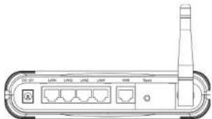
The rear panel of the Wireless Router is shown below
natural_image
Front view of a wireless router device showing ports, cables, and a antenna (no text or labels visible)Power Connection
Plug the circle end of the power adapter firmly into the rear panel of the Wireless Router, and the other end put into an electric service outlet then the system is ready.
Placement (Optional)
There are three ways to place the Router. The first way is to place the Router horizontally on a surface. The second way is to attach the router to the wall. The third way is to stand the Router vertically on a surface. These options are explained in further detail below.
Desktop Option
- The Router has one plastic stand that can be divided into two parts.
- Combine one part of stand with the side of router
- Do the same with the second part.
- Place the Router
Wall-mount option
Before attach this router on the wall, you have to finish the desktop option steps first.
- Select a location with access for cables and a power outlet.
- Urplug the unit. Place it upside down on a flat surface and mark the two holes for anchors.
- Installing the Wall mount anchor (plastic) into the wall with tools such as drill or hammer.
1
- Insert the provided screws in each hole of the stand parts.
- Attaches the unit to the anchors on the wall.
Stand Option
- The Router includes two stand parts.
- Combine two parts into one stand. Combine it with the side of router near the power next. Push the stand up to open it into place.
- Place the Router
7
Installing And Using Wireless Router
This Chapter provides a step-by-step guide to the installation and configuration of the Wireless Router. It assumes that your computers use the Windows 95/98 or newer version and a WEB browser is installed for configuration purposes. We suggest you go over the whole chapter and then do more advanced operation.
Network configuration setup
Steps to build up the network:
Connect the ADSL or Cable modem to the Ethernet WAN port on the back of the Wireless Router being the LTR cable
Connect the phone line from the wall socket to the line-in port on the ADSL
Plug-in the power adapter to the modem and turn on the power. Install the Ethernet card into the computer by referring to the User Guide that came with the card.
Connect the computer to the Wireless Router by using standard twisted-pair Ethernet cable from the computer's Ethernet card to an 10/100Mbps Ethernet port on the back of the Wireless Router.
Plug-in the power adapter to the Router and the other side to the wall outlet.
Computer configuration setup
In order to communicate with Wireless Router, the connected computer needs to install the TCP/IP protocol and setup the related address information.
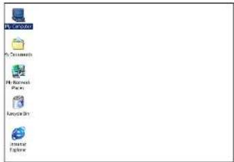
- Double click the "My Computer" icon on the desktop screen
- Double click the "Control Panel" icon on the My Computer window

- Double click the "Network" icon on the Control Panel window

- Click the "Configuration" tab and check the TCP/IP protocol is available or not. If yes, skip the procedures 5 - 6. If no, click the "Add" button.

10
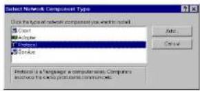
- Select "Protocol" item on the Select Network Component Type window. After that, click "Acid" button
- Select "Microsoft" item on the left side of Select Network Protocol window. After that, select "TCP/IP" protocol on the Network Protocols block and click "OK" button.

- Select the "TCP/IP" component in the Configuration tab of the Network window. Click "Properties" button.
11
- The screen will show up the TCP/IP Properties window then start the setting. First of all, you need to choose the IP address is dynamically assigned by a DHCP server or fixed.

Dynamically assigned:
- Select the "IP Address" tab and select "Obtain an IP address
automatically" (default setting) - Select the "Gateway" tab and click "Remove" to clear any existing entry of
gateway IP address - Select the "DNS Configuration" tab and click "Disable DNS"
- Click "OK" button
Fixed:
If there are some clients who need to get fixed IP addresses for some reasons and the nodes also need to access Internet through the Wireless Router then the following steps used to configure system
Select "Specify an IP address" in the IP Address Tab of the TCP/IP
Properties window and enter 192.168.1.*** in the IP Address field (the *** is a number between 2 and 254 used by the Wireless Router to identify individual computers)
Select the "Subnet Mask" field and enter 255.255.255.0
- Select the "DNS Configuration" tab and click "Enable DNS"
- Enter the DNS IP Address obtained from your ISP in the "Server Search
Order" location. Click "OK" button.
12
NOTE : 1. The default IP address of Wireless Router is 192.168.1.1 and subnet mask is 255.255.255.0
-
For the new network computers to use dynamic IP addresses provided by the Wireless Router DHCP server, they should not use the range of fixed IP addresses. For example, if the fixed IP addresses already use 192.168.1.2 to 192.168.1.68 the DHCP server must be setup to allocate the dynamic addresses out of this range.
-
The screen will return back to Network window then click "OK" button. At this moment, the system will prompt you for restarting the Windows. Click "Yes"
13
Wireless Router configuration setup
In order to make the whole network operate successfully, it is necessary to configure the Wireless Router through your computer has a WEB browser installed. Please follow up the steps listed below.
-
Double click the Internet WEB browser icon on your desktop screen (Netscape Communicator 4.0 and Internet Explorer 3.0 or update version)
-
Type 192.168.1.1 into the URL WEB address location and press Enter.

- The Username and Password Required window appears.
- Enter admin in the User Name location (default value).
- Enter admin in the Password location (default value).
- Click "OK" button

Don't forget to change the Username and Password in configuration's Authentication to ensure the security.
Status
In the home page of the Wireless Router, the left navigation bar shows the options to configure the system. In the right navigation screen is the summary of system status for viewing the configurations.

System Alias Name Name of Router Up-time Total of operation time Firmware version Version of Firmware
- Wireless Configuration SSID This is the name of the wireless LAN. All the devices in the same wireless LAN should have the same SSID. Channel Number The channel used by the wireless LAN. All devices in the same wireless LAN should use the same channel. Encryption Type of Encryption
Associate Clients Number of all active wireless stations that are
connecting to the access point.
BSSID | Basic Service Set Identification of AP
LAN Configuration
IP Address | IP Address of Router
Subnet Mask Subnet Mask
DHCP Server Enabled or Disable of DHCP
MAC Address|MAC Address of LAN-port
WAN Configuration
Attain IP Protocol Static IP address
IP Address IP address of WAN-port
Subnet Mask Subnet Mask of WAN-port
Default Gateway Default Gateway of WAN-port
MAC Address|MAC Address of WAN-port
Wireless
Wireless Access Point builds a wireless LAN and can let all PCs equipped with IEEE602.11b wireless network adaptor connect to your Intranet. It supports WEP encryption and MAC address filter to enhance the security of your wireless network.
Basic Selling
You can set up the configuration of your Wireless and monitor the
eless Clients associate with your AP
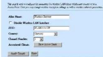
Wireless Basic Settings
Configuration
Alias Name The name of Router
□Disable Wireless LAN To Disable interface of Wireless LAN
Interface
SSID The name of Wireless
Country Select the country where you are to decide the Channel number
Channel Number The channel used by the wireless LAN. All devices in the same wireless LAN should use the same channel.
Associated Clients Click "Show Active Clients" button, then an "Active Wireless Client Table" will pop up. You can see the status of all active wireless stations that are connecting to the access point.
Click

Active Wireless Client Table
MAC Address MAC address of this active wireless station.
Tx Packet The number of transmitted packets that are sent out from this active wireless station.
Rx Packet The number of received packets that are received by this active wireless station.
TX Rate The transmission rate
Power Saving Shows if the wireless client is in Power Saving mode
Expired Time This is the time in second before dissociation. If the wireless keeps idle longer than the expired time, this wireless router will dissociate it. The wireless client station has to associate again when it is active.
Refresh Refresh the "Active Wireless Client Table".
Close Close the "Active Wireless Client Table".
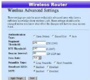
- Advanced Settings
You can set advanced wireless LAN parameters of this router. The parameters include Authentication Type, Fragment Threshold, RTS Threshold, Beacon Interval, Tx Operation Rate, Tx Basic Rate. Preamble Type, and Broadcast SSID. You should not change these parameters unless you know what effect the changes will have on this router.
Configuration
| Authentication Type | Open System mode | Wireless AP can associate with this wireless router without WEP encryption. |
| Shared Key mode | You should also setup WEP key in the "Security" page and wireless AP associating with this wireless router should use WEP encryption in the authentication phase. | |
| Auto | The wireless client can associate with this wireless router by using any one of these two Modes. |
Fragment To specifies the maximum size of packet during the Threshold data transition. The lower values you set, the worst performance it will be.
| RTS Threshold | If the packet size is smaller the RTS threshold, the wireless router will not send this packet by using the RTS/CTS mechanism. |
| Beacon Interval | The period of time how long a beacon is broadcasted. |
| Data Rate | The "Data Rate" is the data packets limitation this wireless router can transmit. The wireless router will use the highest possible selected transmission rate to transmit the data packets. |
| Preamble Type | It defines the length of CRC block in the frames during the wireless communication. "Short Preamble" is suitable for heavy traffic wireless network. "Long Preamble" provides much communication reliability |
| Broadcast SSID | If you enable "Broadcast SSID", every wireless station located within the coverage of this wireless router can discover this wireless router easily. If you are building a public wireless network, enabling this feature is recommended. Disabling "Broadcast SSID" can provide better security. |
| IAPP | To enables multiple AP to communicate and pass information regarding the location of associated Stations. |
Click
- Wireless Security Setup
At the page, you can set up the WEP. WPA Encryption to ensure the security of your Wireless.

Configuration
| Encryption | To enable WEP or WPA encryption, select the option in the drop list. If you select none, any data will be transmitted without Encryption and any station can access the router. |
| Use 802.1x Authentication | To enable the 802.1x, Click the check box of the item. |
| WPA Authentication Mode | There are two items, "WPA-Radius" and "pre-shared key". You can select the mode by clicking the item. |
| WPA Unicast Cipher Suite | To enable "TKIP", click the check box. |
| Pre-Shared key Format | To decide the format, select what you need in the drop list. |
Authentication RADIUS Seven
If you use RADIUS Sever to ensure your security, you have to set up the parameters in the item. To set up the Port, IP address and Password of your RADIUS, Enter the Port Number, IP and Password.
Click
Access Control
To restrict the Number of Access authentication of Stations, Set up the control list in this page.

Configuration
Enable Wireless Access control
To enable it, click the check box.
MAC Address &
To set up the Value of MAC Address & Comment; enter the MAC Address and Comment of station and click Apply Changes to save.
Comment Comment; enter the MAC Address and Comment of station and click Apply Changes to save.
Current Access Control list To Delete the station on the list, Click the check box in the select item and click the "Delete Selected". If you want to delete all stations on the list, click "Delete All" to remove all of them.
Click "Apply Change" at the bottom of the screen to save the above configurations. You can now configure other advance sections or start using the route:
22
WDS Setting

Wireless Distribution System allows the router to communicate with other APs wirelessly. To make it work, you must ensure that these APs and the Router are in the same Channel and add these APs MAC Address and Comment values into the WDS list. Don't Forget to Enable the WDS by click the check box of "Enable WDS" and press "Apply Changes" button to save.
To Delete the AP on the list, Click the check box in the select item and click the "Delete Selected". If you want to delete all APs on the list, click "Delete All" to remove all of them.
23
TCP/IP Setting
• LAN Interface Setup
To set up the configuration of LAN interface, Private IP of you router LAN Port and Subnet mask for your LAN segment.

Configuration
IP address The IP of your Router LAN port (Default 192.168.1.1)
Subnet Mask Subnet Mask of you LAN (Default 255.255.255.0)
802.1d To prevent from network loops and preserve the Spanning tree quality of bridged network
Default To set up the Default Gateway, enter the IP Value.
Gateway
To give your LAN Client an IP, you have to enable
DHCP
DHCP . If not manual setting up your client IP is necessary when you want to use the router as your
client's default gateway.
DHCP Static
To assign an IP for a specified MAC-address, Enter
Assignment
the MAC-address, IP, Comment name in the Text-box and Click iApply Changed to save
24

WAN Interface Setup
In the page, you can set up the three types of Internet Access, PPPoE, DHCP, and Fixed IP.

25
| Ams DNS Automatically | |
| Set DNS Mesqually | |
| DNS 1: | |
| DNS 2: | |
| DNS 3: | |
| Close MAC Address: | 101001000 |
| [] Enable DNS | |
| Service Provider: | testGoogle (5.0" [in-store]) |
| Host Name: | |
| Username: | |
| Password: | |
| Mail Exchanges (*): | |
| [] Enable Webland (*) | |
| * available in online Service Provider: | |
Configuration
| DHCP | If your connection type is DHCP; select "Attain IP automatically (DHCP)". | |
| Fixed IP | When you ISP use Static IP, you have to select "Fixed IP" and enter the IP address, Subnet Mask and Default Gateway provided by Your ISP. | |
| PPPoE | When your connection type is PPPoE. You need to enter the information provided by your ISP, Such as User name, Password, Connection type (continuous, connect on demand and manual), and Idle Time. | |
| Username EX. PeterPassword EX.12345 | ||
| Connection Type | Continuous is for Always keep connection | |
26
| Idle time(Minute) | Connect on demand is for bill by connection time. You can set up the Idle time for the value specifies the number of time that elapses before the system automatically disconnects the PPPoE session. | |
| Manual To connect to ISP, click "Connect" manually from the WEB user interface. The WAN connection will not disconnected due to the Idle timeout. If the WAN line breaks down and latter links again, the router will not auto-connect to the ISP. | ||
| The value specifies the number of idle time that elapses before the system automatically disconnects the PPPoE session. | ||
| DNS | If your DNS provide by ISP is dynamic, choose 'Attain DNS automatically' | |
| To specify the DNS, and enter the DNS provided by your ISP in DNS 1 2 3: | ||
| Clone Mac Address | When ISP use MAC address authentication (with DHCP), then the MAC address of the Ethernet card attached to your Cable modem must be registered with the ISP before connecting to the WAN (Internet). If the Ethernet card is changed, the new MAC address must be registered with the ISP.MAC cloning feature allows the MAC address reported by WAN side network interface card to be set to the MAC address already registered with the ISP eliminating the need to register the new MAC address with the ISP. This feature does not change the actual MAC address on the NIC, but instead changes the MAC address reported by Wireless Router to client requests. | |
| To Change the MAC address, enter it in the text box. | ||
| Enable WAN Access | To Enable the user to access this Router through Internet.Enter the specific IP and the port number | |
| Enable DDNS | The Dynamic DNS feature allows you to dynamically register your assigned IP address to an Internet resolvable Fully Qualified Domain Name (FQDN). This is especially useful if you have a dynamically assigned IP address and you want to maintain a constantly resolvable web address.To enable Dynamic DNS, select Enable in the Dynamic DNS checkbox control, select a dynamic DNS service provider from the Service Provider drop list, and enter the host name, username and password in the Host Name, Username and Password fields.Note: You must create an account with the selected provider before using this feature.Note. Wildcard and Mail Exchanger service depend on the service providers. |
| Enable MTU Setup | To Enable the Maximum Transmission Unit of Router setup. Any packet over this number will be chopped up into suitable size before sending. Larger number will enhance the transmission performance.Enter your MTU number in the text-box to set the limitation. Default is 1500. |
Firewall Configuration
The firewall could not only obstruct outside intruders from intruding your system, but also restricting the LAN users.
Port Filtering To restrict certain type of data packets from your LAN to Internet through the Router, add them on the Current Filtering
Table.

Configuration
| 1. Click the check box of "Enable Port Filtering" to enable the function. |
| 2. Enter the Port range (EX 25-110), Protocol (UDP/TCP), and comment (EX.E-Mail) |
| 3. To Delete the Port range on the list, Click the check box in the select item and click the "Delete Selected". If you want to delete all entries on the list, click "Delete All" to remove all of them. |
Click
IP filtering
The Wireless Router could filter the outgoing packets for security or management consideration. You can set up the filter against the IP addresses to block specific internal users from accessing the
Internet.

Configuration
STEPS 1. Click the check box of "Enable IP Filtering" to enable the function.
-
Enter the specific Local IP address (EX 10.10.3.9), Protocol (UDP/TCP), and comment (EX. Peter)
-
To Delete the IP address on the list, Click the check box in the select item and click the "Delete Selected". If you want to delete all entries on the list, click "Delete All" to remove all of them.
Click
310
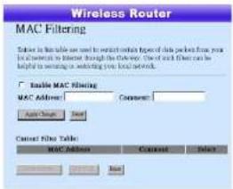
MAC filtering
The Wireless Router could filter the outgoing packets for security or management consideration. You can set up the filter against the MAC addresses to block specific internal users from accessing the Internet.
Configuration
STEPS 1. Click the check box of "Enable MAC Filtering" to enable the function.
-
Enter the specific MAC address (EX 00:0e:b6:a8:72), and comment (EX Peter)
-
To Delete the Mac address on the list, Click the check box in the select item and click the "Delete Selected". If you want to delete all Entries on the list, click "Delete All" to remove all of them.
Click
31
- Port forwarding
The Port Forwarding allows you to re-direct a particular range of service port numbers (from the Internet/WAN Ports) to a particular LAN IP address. It helps you to host some servers behind the router NAT firewall.

Configuration
STEPS
Click the check box of "Enable port forwarding" to enable the function.
Enter the specific IP address (EX 10.10.10.10), Protocol (UDP/TCP), Port range (EX 25-110), and comment (EX, E-Mail)
- To Delete the IP address on the table, Click the check box in the select item and click the "Delete Selected". If you want to delete all Entries on the table, click "Delete All" to remove all of them.
Click
32
Virtual DMZ
The virtual DMZ is used to enable protocols, which need to open ports on the router. The router will forward all unspecified incoming traffic to the host specified in this page.

To configure it, enter the Host IP (private IP address) and Click "Apply changes" to enact the setting.
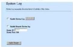
Syslog
View and save the log in remote machine on the page.
To enable the system log,
- Click the check box
- Click show lag to monitor.
To enable the Remote system log, - Click the check box
- Enter the remote machine IP address
33
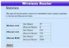
Statistics
On this page, you can monitor the sent & received packets counters of wireless, Ethernet LAN, and Ethernet WAN. To see the latest report, click refresh button.
Upgrade Firmware
To Upgrade Firmware.
STEPS 1. Click "browse..." button to select the firmware you want to upgrade.
- Click Upload to start the upgrade process. Please don't close the WEB-browser and wait for process to complete. When Upgrade is completed, you can start to use the router.

34
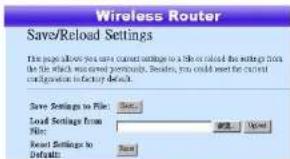
Save and Reload
To save setting to file, click "Save..." button.
To load setting from file.
-
Click "Browse..." on the to select the file
-
Click upload to start the process and wait for it to complete
To reset setting to Default, click reset to start the process and it will be
completed till the status LED start blinking.
Password
To set up the Administrator Account information, enter the Username, New password, and reenter the password on the text box. Don't forget to click the "Apply Changes" to save the configuration.

35
Product Specifications
| Standard | IEEE802 3, 10BASE-T |
| IEEE802 3u, 100BASE-TX | |
| IEEE802 3x full duplex operation and flow control | |
| IEEE802 11b wireless LAN infrastructure | |
| Interface | 1" WAN port |
| 4" 10/100 RJ-45 Fast Ethernet switching ports | |
| One wireless LAN comply with IEEE 802 11b | |
| WAN Connection | Ethernet 10/100 Mbps |
| Cable Connections | RJ-45 (10BASE-T): Category 3.4.5 UTP |
| RJ-45 (100BASE-1X): Category 5 UTP | |
| Network Data Rate | LAN: Auto-Negotiation (10Mbps, 100Mbps) |
| Wireless: 11Mbps, 5.5Mbps, 2Mbps, 1Mbps data rated and auto-fallback support | |
| Transmission Mode | Auto-Negotiation (Full-duplex, Half-duplex) |
| LED indications | System |
| Power | |
| Status | |
| Port (WAN) | |
| ACT/LINK | |
| Port (LAN) | |
| ACT/LINK | |
| Port(Wireless) | |
| A C T | |
| Software Support | Embedded WEB based management interface |
| LAN/WAN management via WEB-based management interface | |
| DHCP client / server function | |
| Firmware upgradeable | |
| PPPoE protocol | |
| NAT / NAPT function | |
| Port filtering | |
| IP filtering | |
| MAC filtering | |
| Virtual DMZ | |
| Wireless Access Point | Built-in 11Mbps wireless Access Point |
| Direct Sequence Spread Spectrum (DSSS) operating at unlicensed 2.4 GHz ISM band | |
| 64/12bit Wired Equivalent Privacy (WEF) data encryption | |
| Emission | FCC CLASS B, CE |
| Operating Temperature | 01~50°C (32°~122°F) |
| Operating Humidity | 10%~90% |
| Power Supply | External Power Adapter, 12VDC/500mA |
Appendix
Service Name, Protocol and Port number
| Service | Protocol | Port | Service | Protocol | Port |
| ANY | Any | Any | ACL | TCP | |
| BGP | TCP | 179 | Finger | TCP | |
| FTP | TCP | 20-21 | Gopher | TCP | 7D |
| HTTP | TCP | 80 | HTTPS | TCP | 443 |
| IMAP | TCP | 143 | InterLocator | TCP | 389 |
| IRC | TCP | 666C-6589 | L2TP | TCP | 1701 |
| VDOLive | TCP | 700C-7010 | WAIS | TCP | 210 |
| WINFRAME | TCP | 1494 | X-WIN | TCP | 6000-6030 |
| DNS | UDP | 53 | KE | UDP | 500 |
| NFS | UDP | 111 | NTP | UDP | 123 |
| PC-Anywhere | UDP | 123 | RIP | UDP | 520 |
| SNMP | UDP | 161 | SYSLOG | UDP | 514 |
| TALK | UDP | 517-518 | TFTP | UDP | |
| UDP-Any | UDP | Any | UUCP | UDP | 540 |
| PING | ICMP | ANY | TRACEROUTE | ICMP | Any |
69
37
G1N3-14010-207
5190-5194 79


- 802.11b Wireless Router User Manual
- FCC Certifications
- CE Mark Warning
- Table of Contents
- Unpacking Information
- Introduction To Wireless Router
- General Description
- Key Features
- The Front Panel
- System LEDs
- Port LEDs (WAN)
- Port LEDs (LAN)
- Port LEDs (Wireless)
- Factory Setting button
- The Rear Panel
- Power Connection
- Placement (Optional)
- Desktop Option
- Wall-mount option
- Stand Option
- Installing And Using Wireless Router
- Network configuration setup
- Computer configuration setup
- Dynamically assigned:
- Fixed:
- Wireless Router configuration setup
- Status
- Wireless
- Configuration
- Active Wireless Client Table
- - Advanced Settings
- - Wireless Security Setup
- WDS Setting
- TCP/IP Setting
- WAN Interface Setup
- Firewall Configuration
- IP filtering
- MAC filtering
- - Port forwarding
- Virtual DMZ
- Syslog
- Statistics
- Upgrade Firmware
- Save and Reload
- Password
Brand : Intellinet
Model : Wireless B Router 523233
Category : Router