S-525 - Loudspeaker Valcom - Free user manual and instructions
Find the device manual for free S-525 Valcom in PDF.


| Product Type | Ceiling Loudspeaker |
| Brand | Valcom |
| Model | S-525 |
| Driver Size | 5.25 inches |
| Impedance | 70V / 100V line |
| Power Handling | 5 Watts (RMS) |
| Frequency Response | 80 Hz - 20 kHz |
| Sensitivity | 90 dB (1W/1m) |
| Coverage Angle | 120 degrees conical |
| Dimensions (Diameter x Depth) | 8.5 x 3.5 inches |
| Weight | 1.3 lbs |
| Mounting Type | Ceiling tile (drop-in) |
| Color | White (paintable grille) |
| Material | Steel backbox, metal grille |
| Connector Type | Screw terminals |
| Operating Temperature | 0°C to 50°C |
| Application | Indoor paging and background music |
| Certification | UL, CE |
| Included Accessories | Mounting plate, screws, wire nuts |
| Warranty | Limited 1 year |
Frequently Asked Questions - S-525 Valcom
User questions about S-525 Valcom
0 question about this device. Answer the ones you know or ask your own.
Ask a new question about this device
Download the instructions for your Loudspeaker in PDF format for free! Find your manual S-525 - Valcom and take your electronic device back in hand. On this page are published all the documents necessary for the use of your device. S-525 by Valcom.
USER MANUAL S-525 Valcom
P-TEC VOICE PAGING SPEAKER S-525
INTRODUCTION
Clarity P-TEC Voice Paging Speakers are suitable for voice paging as well as background music. The S-525 is a 70 Volt model with adjustable taps and volume control. P-TEC speakers consist of a 3.6 inch cone speaker mounted in a unique surface-mount baffle. The baffle is designed for mounting on acoustic tile, such as those normally found in suspended-ceilings; and can be mounted without cutting large holes in the tile. The mounting pins can be removed for mounting in a hard ceiling. The speaker housing has screw holes for securing speaker without mounting pins. Although the P-TEC speakers are designed especially for standard suspended ceilings, they can be used on many types of ceiling materials. P-TEC speakers are not suitable for use in plenum ceiling environments.
DIMENSIONS/WEIGHT
- 8.00"Dia. x 2.50"D (20.32cm x 6.35cm) 1.25 lbs. (.57 kg)
INSTALLATION
Selecting the Power-Tap Wire
- Remove the Quick-Connect connector from the accessory pack.
- Select the desired power-tap wire:
Yellow = 1/4 Watt
Red = 1/2 Watt
Green = 1 Watt
White = 2 Watt
Blue = 4 Watt
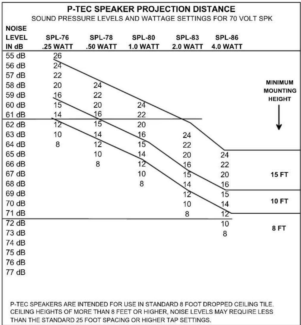
Note: Refer to spacing chart (Figure 6) for recommended speaker spacing.
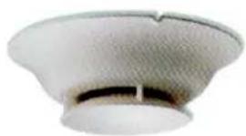
natural_image
Close-up of a white ceramic bowl with a textured rim and a dark horizontal bar at the bottom (no text or symbols visible)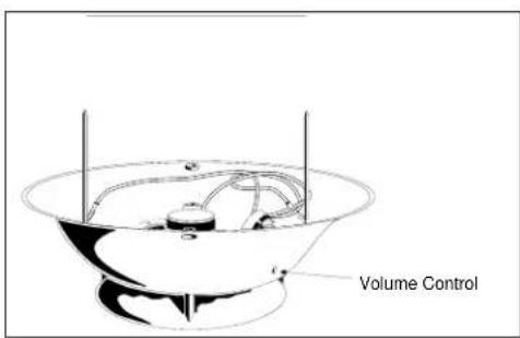
Figure 1. 70 Volt P-TEC Paging Speaker
- Install the Quick-Connect connector on the wire. Use pliers to close the connector over the wire. The connector can be removed by prying it open with a screwdriver, and can be reused several times (See Figure 2).
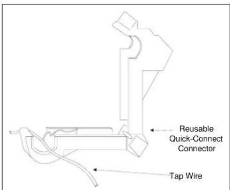
Figure 2. Attaching the Reusable Quick-Connect Connector
-
Connect the power-tap wire to the gold (+) terminal (See Figure 3).
-
Arrange the unused power-tap wires neatly inside the speaker housing and tape them to the inside of the housing.
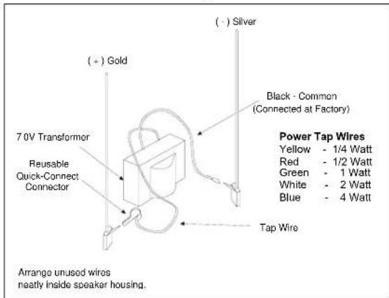
Figure 3. Connecting the Tap Wire
Suspended Ceiling
Note: Wrap wires around strain relief posts so speaker wires will not pull free.
-
Lift the adjacent ceiling tile and slide it out of the way.
-
Install the speaker by inserting the mounting pins through the ceiling tile, and hold the speaker in place.
-
Place the wire and washers, and speaker mounting clips over mounting pins (so pins slide through clips).
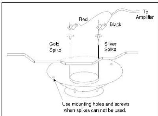
Figure 4. Clarity P-TEC Installation
Note: Washers provide isolation from the pins if the back of the tile is covered with metal foil.
-
If necessary, adjust paging volume after installation. The volume control is located on the side of the speaker. Use a small screwdriver to turn the control.
-
Install the volume control cover found in the accessory pack.
Note: The music volume should be adjusted at the paging amplifier or music source. Adjust paging before adjusting background music.
Maintain Speaker Phasing
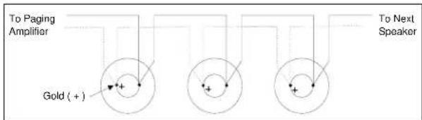
When using multiple speakers in a single run, keep speakers in phase by connecting the speaker wires to the same spike on each speaker (Either wire can connect on either spike, as long as the pattern is followed on each speaker). The gold spike is the plus (+) terminal (See Figure 5).
flowchart
graph TD
    A["To Paging Amplifier"] --> B["Gold (+)"]
    B --> C["To Next Speaker"]
    C --> D["+"]
    style A fill:#f9f,stroke:#333
    style B fill:#ccf,stroke:#333
    style C fill:#cfc,stroke:#333
Figure 5. Maintaining Speaker Phasing
Handling Shielded Speaker Cable
If you are using shielded speaker cable, splice the shield wire at the speaker location so a continuous shield is maintained. When connecting a single speaker, or the last speaker on the run, clip the shield wire where it emerges from the outer insulation on the speaker cable.
TECHNICAL ASSISTANCE
When calling, have a VOM and a telephone test set available and call from the job site. Call (540) 767-1550 for Clarity Technical Support, or call (540) 767-1555 for Valcom 24-hour Fax-back System or visit our websites at http://www.clarity-com.com and www.valcom.com. Should repairs be necessary, attach a tag to the unit clearly stating company name, address, phone number, contact person and the nature of the problem. Send the unit to:
Clarity Repair and Return Dept. 5614 Hollins Road Roanoke, VA 24019-5056
line
| NOISE LEVEL IN dB | SPL-76 .25 WATT | SPL-78 .50 WATT | SPL-80 1.0 WATT | SPL-83 2.0 WATT | SPL-86 4.0 WATT | | ----------------- | --------------- | --------------- | --------------- | --------------- | --------------- | | 55 dB | 26 | | | | | | 56 dB | 24 | | | | | | 57 dB | 22 | | | | | | 58 dB | 20 | 24 | | | | | 59 dB | 16 | 22 | | | | | 60 dB | 15 | 20 | 24 | | | | 61 dB | 14 | 16 | 22 | | | | 62 dB | 12 | 15 | 20 | | | | 63 dB | 10 | 14 | 16 | 24 | | | 64 dB | 8 | 12 | 15 | 22 | | | 65 dB | | 10 | 14 | 20 | 24 | | 66 dB | | 8 | 12 | 16 | 22 | | 67 dB | | | 10 | 15 | 20 | | 68 dB | | | 8 | 14 | 16 | | 69 dB | | | | 12 | 15 | | 70 dB | | | | 10 | 14 | | 71 dB | | | | 8 | 12 | | 72 dB | | | | | 10 | | 73 dB | | | | | 8 | P-TEC SPEAKERS ARE INTENDED FOR USE IN STANDARD 8 FOOT DROPPED CEILING TILE. CEILING HEIGHTS OF MORE THAN 8 FEET OR HIGHER, NOISE LEVELS MAY REQUIRE LESS THAN THE STANDARD 25 FOOT SPACING OR HIGHER TAP SETTINGS.Figure 6
Brand : Valcom
Model : S-525
Category : Loudspeaker