
H-CCR8085 - Car stereo HYUNDAI - Free user manual and instructions
Find the device manual for free H-CCR8085 HYUNDAI in PDF.


| Brand | Hyundai |
| Model | H-CCR8085 |
| Product Type | Car Stereo / Autoradio |
| Form Factor | 1-DIN |
| Dimensions (approx) | 178 x 50 x 160 mm (W x H x D) |
| Weight | Approx. 1.2 kg |
| Power Supply | 12 V DC (negative ground) |
| Maximum Output Power | 4 x 50 Watts |
| Supported Radio Bands | FM (87.5 – 108 MHz), AM (530 – 1710 kHz) |
| Playback Media | USB, SD/MMC card, AUX input |
| Bluetooth | Built-in for hands-free calling and audio streaming |
| Display | LCD with white backlight |
| Remote Control | Included |
| Audio Preset Equalizer | Multiple presets (Rock, Pop, Classic, etc.) |
| Front Panel | Detachable faceplate for security |
| USB Port | Front USB 2.0 |
| AUX Input | 3.5 mm front auxiliary input |
| Steering Wheel Control Compatibility | Yes (with optional adapter) |
| RCA Preamp Outputs | 2 pairs (front/rear) |
| Subwoofer Output | Yes (mono RCA) |
| Operating Temperature | -10°C to +60°C |
| Certifications | CE, RoHS |
Frequently Asked Questions - H-CCR8085 HYUNDAI
User questions about H-CCR8085 HYUNDAI
0 question about this device. Answer the ones you know or ask your own.
Ask a new question about this device
Download the instructions for your Car stereo in PDF format for free! Find your manual H-CCR8085 - HYUNDAI and take your electronic device back in hand. On this page are published all the documents necessary for the use of your device. H-CCR8085 by HYUNDAI.
USER MANUAL H-CCR8085 HYUNDAI

natural_image
Two glossy spheres with reflections on a white background (no text or symbols)USB/SD/MMC MEDIA PLAYER
USB/SD/MMC-MEDIAPLEEP
Table of contents
Dear customer!
Thank you for purchasing our product. For safety, it is strongly recommended to read this manual carefully before connecting, operating and/or adjusting the product and keep the manual for reference in the future.
Table of contents 2
Before you start 3
Utilization of the product 3
Important safeguards 3
Installation/Connection 4
Installation 4
General notes 4
- DIN front-mount (Method A) 4
Trim frame installation 4
- DIN rear-mount (Method B) 4
Dismantling the unit 4
Detachable control panel 5
Anti-theft system 5
Connection 6
Connection diagram 6
Using the ISO Connector 6
Operation 7
Control elements 7
Front panel 7
Inner panel 7
LCD layout 8
General operations 9
Turning on/off 9
Mode selection 9
Volume control 9
Mute function 9
Loudness 9
Audio parameter setting 9
Preset EQ modes 9
Beep function 9
Clock 9
Preset volume 9
AUX in jack 9
Radio operations 9
Band select 9
Manual tuning/Automatic tuning 9
Storing and recalling stations 9
Mono/stereo control 10
RDS function 10
AF (Alternative Frequency) function ..... 10
TA (Traffic Announcement) function .... 10
PTY (Program type) 10
Other parameter setting 11
USB/SD/MMC operations 11
Connecting a USB/memory card 11
Playback 11
Track select 11
Folder select 11
Fast forward/rewind 11
Pause 11
Intro playback 11
Repeat 12
Random 12
ID3-tags 12
General information 13
Troubleshooting guide 13
Cleaning the unit body 13
Accessories 13
Specification 14
Utilization of the product
If you want to dispose this product, do not mix it with general household waste. There is a separate collection system for used electronic products in accordance with legislation that requires proper treatment, recovery and recycling.
Please contact your local authorities for the correct method of disposal. By doing so, you will ensure that your disposed product undergoes the necessary treatment, recovery and recycling and thus prevent potential negative effects on the environment and human health.
Important safeguards
- Read carefully through the manual to familiarize yourself with this unit.
- Keep this manual handy as a reference for operating procedures and precautions. Do not allow persons who have not read through this manual to use this unit.
- Do not allow this unit to come into contact with liquids. Electrical shock could result. Also, damage to this unit, smoke, and overheating could result from contact with liquids or dust. Protect this unit from moisture.
- Make sure that foreign objects do not get inside the unit; they may cause malfunctions, or create safety hazards such as electrical shock or laser beam exposure.
- The beginning of operation is the moment of the unit installation. Before use the device in winter it is recommended to heat up the passenger compartment during 20 seconds or to the operation temperature.
- Using the unit with the temperature that goes beyond the operation temperature greatly decreases the operation resource of the screen and other components of the unit and can result in an outage.
- Disconnect the vehicle's negative battery terminal while mounting and connecting the unit.
-
The unit is designed for negative terminal of the battery, which is connected to the vehicle metal. Please ensure it before installation.
-
When replacing the fuse, be sure to use one with an identical amperage rating. Using a fuse with a higher amperage rating may cause serious damage to the unit.
- Do not allow the speaker wires to be shorted together when the unit is switched on. Otherwise it may overload or burn out the power amplifier.
- Make sure you disconnect the power supply and aerial if you will not be using the system for a long period or during a thunderstorm.
- Make sure you disconnect the power supply if the system appears to be working incorrectly, is making an unusual sound, has a strange smell, has smoke emitting from it or liquids have got inside it. Let a qualified technician check the system.
• Always keep the volume low enough so that you can hear sounds from outside the vehicle. - Should this product fail to operate properly, contact your dealer or nearest service center.
Installation
General notes
- Choose the mounting location where the unit will not interfere with the normal driving function of the driver.
- Before finally installing the unit, connect the wiring and make sure that the unit works properly.
- Consult with your nearest dealer if installation requires the drilling of holes or other modifications of the vehicle.
- Install the unit where it does not get in the driver's way and cannot injure the passenger if there is a sudden stop, like an emergency stop.
- Avoid installing the unit where it would be subject to high temperature, such as from direct sunlight, or from hot air, from the heater, or where it would be subject to dust, dirt or excessive vibration.
DIN front-mount (Method A)
- Install the sleeve into the dashboard; ensure it is installed with the correct side and there are no obstacles (wires, dashboard elements, etc) for the unit installation.
- After installing the sleeve into the dashboard, bend tabs fitting to the size of the dashboard to fix the sleeve in place.
- Make the necessary wire connections. Ensure the connections are correct.
- Install the unit into the sleeve until the side locks are fixed.
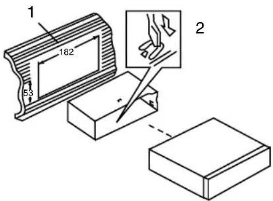
- Dashboard
- Sleeve tab to bend
Trim frame installation
To install the trim frame, press it to the unit body and push it to fix it in place. This should be done before installing the front panel; otherwise you are not able to install the trim frame.
DIN rear-mount (Method B)
For this method, use the screw holes in the lateral sides of the unit. Fix the unit with the help of the factory radio mounting brackets.
- Select a position in which the screw holes of the brackets (3) are aligned with the screw holes in the unit body, and screw in two screws (2) in each side.
- Screw.
- Factory radio mounting brackets.
- Vehicle dashboard.
- Lock (remove this part).
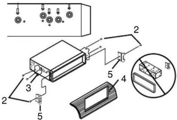
The outer trim frame and mounting sleeve are not used for method of installation.
Dismantling the unit
a - Trim frame
b – Frame uninstall direction
c – Release key insertion
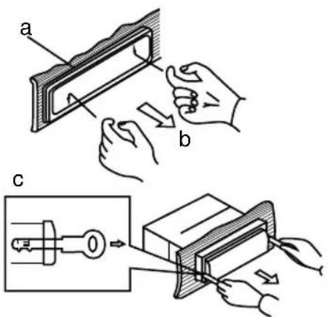
- Switch off the unit and detach the front panel.
- Insert your fingers into the groove in the front side of the trim frame (apply some effort to detach the frame). Pull the frame to detach it.
- Insert the supplied release keys into the both sides of the unit body to click, as shown in the picture. To extract the unit from the dashboard, pull the release keys or the unit body to pull it out.
Detachable control panel
Install the fastening hole on the right side of the front panel on the right fastening of the unit. Then insert the left fastening on the panel into the fixing hole on the left part of the unit. Press on the upper right part of the panel until a click. Ensure that the panel is properly fixed, otherwise error symbols may be displayed and some buttons may not function.
To detach the front panel, press OPEN button, then distract the left side of the panel from the fastening of the unit.
The control panel can easily be damaged by shocks. After removing it, place it in a protective case and be careful not to drop it or subject it to strong shocks. The rear connector that connects the main unit and the control panel is an extremely important part. Be careful not to damage it by pressing on it with fingernails, pens, screwdrivers, etc.
If the control panel is dirty, wipe off the dirt with soft, dry cloth only. And use a cotton
swab soaked in isopropyl alcohol to clean the socket on the back of the control panel.
Anti-theft system
The front panel of this unit can be stored in the included protective case when not in used and carried away when you leave the vehicle to deter theft.
Switch off the power of the unit. Detach the front panel, then put it to the protective case and take it with you.
Connection
Connection diagram
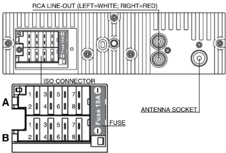
Using the ISO Connector
- If your car is equipped with the ISO connector, then connect the ISO connectors as illustrated.
- For connections without the ISO connectors, check the wiring in the vehicle carefully before connecting, incorrect connection may cause serious damage to this unit.
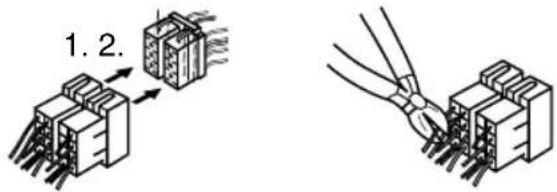
Cut the connector, connect the colored leads of the power cord to the car battery as shown in the color code table below for speaker and power cable connections.
| Location | Function | |
| Connector A Connector B | ||
| 1 Rear right (+) - Blue - | ||
| 2 Rear right (-) - Blue/White - | ||
| 3 Front right (+) - Grey - | ||
| 4 Front right (-) - Grey/White Battery +12V/Yellow | ||
| 5 Front left (+) - Green Power antenna/Orange | ||
| 6 Front left (-) - Green/White - | ||
| 7 Rear left (+) - Brown Ignition/Red | ||
| 8 Rear left (-) - Brown/White Ground/Black | ||
Power antenna wire is intended for power supply of the antenna and for remote control of an additional amplifier.
Control elements
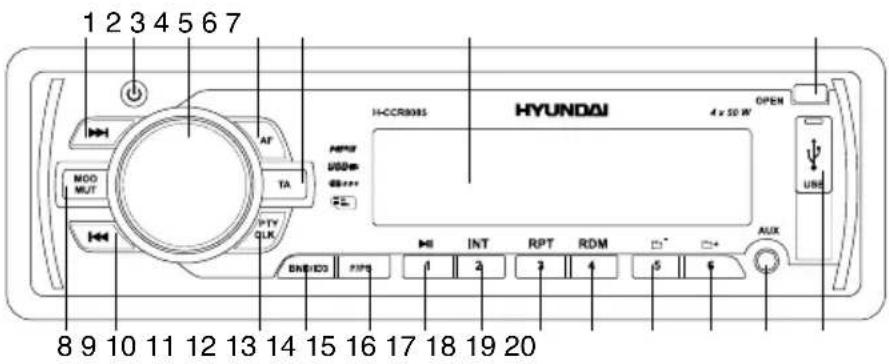
Front panel
- button
- PWR button
- VOLUME knob/SELECT button
- AF button
- TA button
- Display
- OPEN button
- MOD/MUT button
- Button
- PTY/CLK button
- BAND/ID3 button
- F/PS button
- 1/▶ button
- 2/INT button
- 3/RPT button
- 4/RDM button
- 5/- button
- 6/ + button
- AUX in jack
- USB port
Inner panel
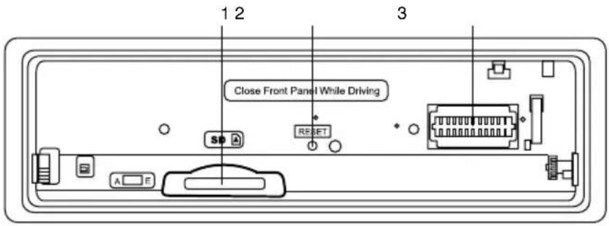
- SD/MMC card slot
- RESET button (hole)
- Connector

Pressing RESET hole will erase the
clock setting and stored stations.
LCD layout
![29 28 LOUD VIDEO MUSIC ALBUM FOLDER ARTIST RPT INT RDM EON AF TA TP PTY [SYSTEM EP] Sub-W ESP WMA MP3 MUTE 1 2 3 4 5 6 7 8 9 10 11 12 13 14 15 16 17 18 19 20 21 22](/content/2026/05/1046299/images/812828fa5b5d655586bde7b6c7947ac29e8f05e0d8b8ba0554528ec0b0f914ea.jpg)
- Video playback indicator
- Music playback indicator
- Album name on
- File name on
- Folder name on
- Repeat mode indicator
- Artist name on
- Intro mode on
- Random playback on
- ROCK equalizer mode
- POP equalizer mode
- EON function indicator
- CLASS equalizer mode
- AF function indicator
-
FLAT equalizer mode
-
TA function indicator
- Equalizer indicator
- TP function indicator
- PTY function indicator
- Mute mode indicator
- Stereo reception indicator
- Signal indicator
- MP3 playback
- WMA playback
- ESP function indicator
- Subwoofer indicator (not active)
- Digit display (radio frequency, track number/name, etc.)
- Disc loading indicator
- Loudness function indicator
General operations
Turning the unit on/off
Press PWR button to turn the unit on. Press the button again to turn the unit off.
Mode select
Press MOD/MUT button repeatedly to select between Radio, auxiliary input, USB or Memory Card modes. Modes of operation are indicated on the display. Memory card and USB modes are not available unless a memory card or USB device is connected.
Volume control
Adjust volume by rotating VOLUME knob (00-42).
Mute function
Press and hold MOD/MUT button to switch off the sound; press it again or rotate VOLUME knob to resume the sound.
Loudness
Press SELECT button repeatedly until LOUD ON (OFF) is displayed. Rotate VOLUME knob to select loudness ON or OFF. Activating this feature will enhance bass and treble frequencies when listening to music at low volumes.
Audio parameter setting
Press SELECT button repeatedly to select a parameter: VOL (volume) => BAS (bass) => TRE (treble) => BAL (balance) => FAD (fader). Rotate VOLUME knob to adjust each mode:
- Bass/Treble: from -10 to 10;
• Balance: L10 (left) to R10 (right); - Fader: from R10 (rear) to F10 (front).
When DSP is on, bass and treble are not adjustable.
Preset EQ modes
Press SELECT button repeatedly until EQ OFF is displayed. Rotate VOLUME knob to select between FLAT/CLASS/ROCK/POP and OFF equalizer modes.
Beep function
Press SELECT button repeatedly until BEEP ON (OFF) is displayed. Rotate VOLUME knob to select between ON (beep sound is heard when a button is pressed) and OFF (no sound is heard when a button is pressed).
Clock
Press and hold PTY/CLK button to display the time on the screen. Then press and hold this button again; the time indication will blink. Press ▶▶▶ button to adjust hours; press ◀◀◀ button to adjust minutes. To confirm the adjustment, press PTY/CLK button or leave the unit idle for several seconds.
Preset volume
Press and hold SELECT button, then press it until P-VOL is displayed. Rotate VOLUME regulator to adjust the preset volume level. This volume level will be active each time you switch on the unit.
Aux In
AUX-in jack is intended for connecting an external audio equipment to amplify the sound. If connection is made correctly, the audio signal from the external source will be translated through the acoustics of the head unit. This enables to adjust the volume and quality of the sounding. For example, you can connect an MP3-player to listen to tracks using the car acoustic system.
Radio operations
Band select
In Radio mode press BND/ID3 button to select a radio band: FM1, FM2, FM3 and AM1, AM2. 6 stations can be saved in each band.
Manual/automatical tuning
- Press and hold buttons to display MANUAL. Now you can press these buttons repeatedly to adjust the needed frequency
manually.
- To adjust the needed frequency automatically, press instructions. The radio will seek to the next down or up strong and clear frequency station. Repeat this action to seek for other desired stations.
Storing and recalling stations
To store a station
To store a station, select the desired band and station. Press and hold the desired number button for more than 2 seconds. When stored, the preset number will appear on the display. The station can be recalled anytime by pressing the corresponding number button.
Store stations automatically
- Press and hold F/PS button for more than 2 seconds to automatically find and store 6 strongest stations in the current band.
- After the 6 strongest stations are saved, press F/PS button; scanning of all stored station will begin.
Mono/Stereo control (in FM radio mode)
Press SELECT button repeatedly until the display shows STEREO (MONO). Turn VOLUME knob to switch between stereo reception or mono reception.
Improvement of reception of distant stations can be done by selecting mono mode, which may cut down some reception noise.
RDS function
RDS (Radio Data System) service availability varies with areas. Please understand if RDS service is not available in you area, the following service is not available, either.
AF (Alternative Frequencies) function
Press AF button on the panel to turn the AF function on or off.
When the radio signal strength is poor, enabling the AF function will allow the unit to automatically search another station with the same PI (Program Identification) as the current station but with a stronger signal, so that you do not have to retune the stations when driving between different transmitter coverage areas. When AF symbol is on, it means RDS information is received; when AF symbol is flashing, it means RDS information is not yet received.
PS (Program Service name): the name of station will be display instead of frequency.
If RDS service is not available in your area, turn off the AF mode. Default setting is ON.
TA (Traffic Alarm) function
Press TA button to turn TA function on or off.
In TA mode traffic program will be automatically searched, until the program is received. When traffic announcement is received the unit will temporarily switch to the tuner mode (regardless of the current mode) and begin broadcasting the announcement. After the traffic announcement is over, it will return to the previous mode and volume level. To interrupt traffic announcement press TA button shortly; it will not switch off the TA mode.
PTY (Program Type)
This radio will allow you to select the type of program required, and will search for a station broadcasting that type of program.
Press PTY/CLK button to show the music type. Then press 1 - 6 number buttons to choose different music programs available.
Press PTY/CLK button twice to show the speech type. Then press 1 - 6 number buttons to choose different speech programs. Each number button will show 3 different speech programs for you to choose (see table below).
| Button | Music group | Speech group |
| 1 Pop | Rock News, Affairs, Info | |
| 2 Easy | Light Sport, Educate, Drama | |
| 3 Classics Culture, Science, Varied | ||
| 4 Jazz, Country Weather,Finance, Children | ||
| 5 Nation, Oldies Social, Religion,Phone IN | ||
| 6 Folk Travel, Leisure,Document | ||
When PTY is selected, the radio starts to search corresponding PTY information, and stops if the corresponding PTY information is detected. If no buttons are pressed within several seconds, previously selected PTY is searched. During 1 loop, if desired PTY is not found, the unit will return to previous mode. Press PTY/CLK button to switch the PTY function off.
Other parameter setting
To choose the corresponding option, press and hold SELECT button for 2 seconds, then press it repeatedly until the display shows the needed option. Turn VOLUME knob to choose the needed value. After choosing, leave the unit idle to activate.
TA SEEK/TA ALARM
In TA SEEK mode, the unit will seek for traffic announcement program when TA button is pressed; in TA ALARM the unit does not retune to TA information.
PI SOUND/PI MUTE
PI sound refers to the reception noise when the AF function tries to scan alternative frequency.
MASK DPI/MASK ALL
During MASK DPI mode, the unit will mask only the AF which has different PI, this is the default mode; during MASK ALL mode, the unit will mask the AF which has different PI and no RDS signal with high field strength.
RETUNE S/L - SHORT/LONG
"RETUNE" refers to the time period the unit allows for radio scan when reception is interrupted. "S" represents a long time period, and "L" represents a short time period.
USB/SD/MMC operations
Connecting a USB-device/Memory card
Insert a USB device into the USB port of this unit. Or detach the front panel and insert an SD/MMC memory card until a click into the memory card slot. To remove the card, press it until a click, then pull to remove.
USB/SD/MMC supported capacity: up to 16 Gb.
For correct and satisfactory operation, licensed SD/MMC memory cards of famous brands should be used with this unit. Avoid using memory cards of unknown brands. Some models of USB devices cannot be supported by this unit due to incompatibility.
Playback
When a USB or a memory card is first connected, playback will begin automatically.
Depending on the number of files and folders, the device may take several seconds to begin playback. If no MP3/WMA files are detected, "USB" or "SD" will be displayed.
Track select
- Press ▶ button to skip to the beginning of the next track. Press ◀ button to skips to the previous track.
- Press F/PS button; track number will blink on the display. Rotate VOLUME knob to select the track number. Press SELECT button to confirm your selection.
Folder select
Press 5/-button to select the previous folder. Press 6/+button to select the next folder.
Fast forward/rewind
Press and hold for button to rewind or fast forward the current track.
Pause
Press 1/▶ button to temporarily stop file
Operation
playback. Press it again to resume playback.
Intro playback
Press 2/INT button to play first 10 seconds of each track consequently. Press again to cancel.
Repeat
Press 3/RPT button to continuously repeat the current track. Press again to cancel.
Random
Press 4/RDM button to play all the tracks in the current folder in random order. Press again to cancel.
ID3-tags
If an MP3 file contains ID3 information, such information will be displayed during the file playback. For display of various ID3-tag categories (folder/file/title/artist/album name) press BND/ID3 button repeatedly.
This unit may not support some version of ID3-tag information.
Troubleshooting
Below is a table describing simple measures that can help you eliminate most problems likely to emerge when this unit is in use. If below measures do not help, turn to a service center or to the nearest dealer.
| Symptom Cause Solution | ||
| No power Wiring is | connected incorrectly. Make correct wiring connection. | |
| The car ignition is not on. If the power supply is properly connected to the car accessory switch the ignition on. | ||
| The fuse is blown. Replace the fuse. | ||
| No sound Volume is | in minimum. Adjust volume to a desired level. | |
| Wiring is not properly connected. | Check wiring connection. | |
| The radio does not work | The antenna cable is not connected. | Insert the antenna cable properly. |
| The radio station automatic tuning does not work | The signals are too weak. Select stations manually. | |
Cleaning the unit body
Wipe with a soft cloth. If the cabinet is very dampen (not dropping wet) the cloth with a weak solution of soapy water, and then wipe clean.
Accessories
- Receiver 1 pc
- Front panel 1 pc
- Protective case for the front panel ... 1 pc
- ISO connector 1 pc
- Mounting parts: Screw M5x5 mm .... 4 pcs Release key .... 2 pcs Mounting collar .... 1 pc Trim frame .... 1 pc
- Instruction manual 1 pc
- Warranty card 1 pc
- Consumer information 1 pc
Specifications
General
Maximum power output: 4 x 50 W
Suitable speaker impedance: 4-8 Ohm
Fuse: 10 A
Storage support: USB/SD/MMC up to 16 Gb
Dimensions/Weight: 178 x 50 x 115 mm/1.8 kg
Temperature range: -20 ^ C - +60 ^ C
FM Stereo Radio
Frequency range: 87.5 - 108.0 MHz
Presettable stations: 18
Stereo separation: 35 dB (1 kHz)
MW (AM) Radio
Presettable stations: 12
Frequency range: 530-1710 kHz
Usable sensitivity: 30 dBμ
Line out: Stereo RCA line-out (2 V)
Specifications are subject to change without notice. Dimensions are approximate.
natural_image
Diagram showing two configurations of connector pins with arrows indicating connection (no text or symbols present)| Button | Music group | Speech group |
| 1 Pop | Rock News, Affairs, Info | |
| 2 Easy | Light Sport, Educate, Drama | |
| 3 Classics Culture, Science, Varied | ||
| 4 Jazz, Country Weather, Finance, Children | ||
| 5 Nation, Oldies Social, Religion, Phone IN | ||
| 6 Folk Travel, Leisure, Document |
- Table of contents
- Dear customer!
- Table of contents 2
- Before you start 3
- Installation/Connection 4
- Operation 7
- General information 13
- Utilization of the product
- Important safeguards
- Installation
- General notes
- DIN front-mount (Method A)
- Trim frame installation
- DIN rear-mount (Method B)
- Dismantling the unit
- Detachable control panel
- Anti-theft system
- Connection
- Connection diagram
- Using the ISO Connector
- Control elements
- Front panel
- Inner panel
- General operations
- Turning the unit on/off
- Mode select
- Volume control
- Mute function
- Loudness
- Audio parameter setting
- Preset EQ modes
- Beep function
- Clock
- Preset volume
- Aux In
- Radio operations
- Band select
- Manual/automatical tuning
- Storing and recalling stations
- To store a station
- Store stations automatically
- Mono/Stereo control (in FM radio mode)
- RDS function
- AF (Alternative Frequencies) function
- TA (Traffic Alarm) function
- PTY (Program Type)
- Other parameter setting
- TA SEEK/TA ALARM
- PI SOUND/PI MUTE
- MASK DPI/MASK ALL
- RETUNE S/L - SHORT/LONG
- USB/SD/MMC operations
- Connecting a USB-device/Memory card
- Playback
- Track select
- Folder select
- Fast forward/rewind
- Pause
- Operation
- Intro playback
- Repeat
- Random
- ID3-tags
- Troubleshooting
- Cleaning the unit body
- Accessories
- Specifications
- General
- FM Stereo Radio
- MW (AM) Radio
Brand : HYUNDAI
Model : H-CCR8085
Category : Car stereo