
DFM-40-B - Industrial pneumatic component Festo - Free user manual and instructions
Find the device manual for free DFM-40-B Festo in PDF.


| Product Type | Guided Pneumatic Cylinder |
| Brand | Festo |
| Model | DFM-40-B |
| Bore Size | 40 mm |
| Stroke Length | Up to 500 mm (typical) |
| Operating Pressure | 2 to 10 bar |
| Operating Temperature | -20 to +80 °C |
| Weight | Approx. 2.5 kg (depending on stroke) |
| Dimensions (Length x Width x Height) | Approx. 200 x 80 x 80 mm (without stroke) |
| Guide Type | Ball bushing guide |
| Position Sensing | Compatible with proximity sensors (e.g., SME/SMT) |
| Mounting Type | Via threaded holes and accessories |
| Piston Rod End | Internal thread (M8 or M10 typical) |
| Main Functions | Linear motion with precise guidance |
| Maintenance | Periodic lubrication of guide rails; check seals |
| Cleaning | Wipe with dry cloth; avoid aggressive solvents |
| Safety Precautions | Depressurize before maintenance; avoid exceeding max pressure |
| Spare Parts | Seals, guide bushings, piston rod (contact Festo) |
| Repairability | Seals and guide bushings replaceable; cylinder can be disassembled |
| Certifications | CE, RoHS, REACH |
Frequently Asked Questions - DFM-40-B Festo
User questions about DFM-40-B Festo
0 question about this device. Answer the ones you know or ask your own.
Ask a new question about this device
Download the instructions for your Industrial pneumatic component in PDF format for free! Find your manual DFM-40-B - Festo and take your electronic device back in hand. On this page are published all the documents necessary for the use of your device. DFM-40-B by Festo.
USER MANUAL DFM-40-B Festo
Assembly instructions (Original instructions)
8063354
2017-04e [8065800
FESTO
Guide unit
DFM-...-B
Festo SE & Co. KG
Ruiter Straße 82
73734 Esslingen Germany
+49 711 347-0
www.festo.com
1. Applicable documents
All available documents for the product → www.festo.com/pk
2. Safety
- Switch off compressed air before mounting work.
- Protect the positioning range from access.
- Keep foreign objects out of the positioning range.
3. Intended use
Stop, stopper cylinder or a single-axis feeding unit with larger loads on the yoke plate.
4. Further information
Characteristic curves and permissible limits → www.festo.com/catalogue Accessories (e.g., slot cover ABP) → www.festo.com/catalogue
- Scope of delivery
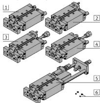
- Not in scope of delivery

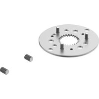
7 Screw (2x)
1) Required surface (I) evenness precision only in case of the GF variants:
DFM-12 ... 20-B = 0.02 DFM-25 ... 63-B = 0.05
In case of non-observance of the evenness precision, guide rods can become jammed.
2) The usage of centring sleeves is not possible for DFM-20 ... 40-B and mounting variant d
3) In the case of DFM-...-B-...-E], the mounting variant d) is possible only to a limited extent,
since the fastening holes are largely covered.
4) Additional, required dimensions of the guide units 1 through 5 can be found in the
catalogue (→ www.festo.com/catalogue)
7. Mounting, general
→ Note
In order to avoid operative malfunctions and increased wear:
- Observe the characteristic curves and permissible limits
- Handle the guide units 1 through 5 in such a way that the guide rods and piston rod are not damaged.
• Ensure that the mounting surfaces (H) and (I) are flat.
• Install guide units 1 through 5 without distortion
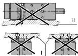

Mounting variants:
a) Flat from on top
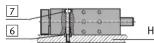
c) Lateral from underneath

b) Flat from underneath

- Use the following screws 7 and centring sleeves 6, depending on the mounting variant:
| DFM----B (a) b) c) + d) Yoke plate (J) | ||||||||
| 12 | M4 | ZBH-9 | M5 | ZBH-9 | M4 | ZBH-5 | M4 | |
| 16 | M6 | ZBH-7 | M5 | |||||
| 20 | M5 | 2) | ZBH-9 | |||||
| 25 | M6 | |||||||
| 32 | M6 | ZBH-12 | M8 | ZBH-12 | ZBH-92) | |||
| 40 | M8 | |||||||
| 50 | ZBH-12 | M8 | ZBH-12 | |||||
| 63 | M8 | M10 | M10 | M10 | ||||
- Provide mounting holes for the centring sleeves 5 on the surfaces (H) and (I) ^4 .

| ZBH | 5 | 7 | 9 | 12 | 15 | |
| D1 ^H7 | [mm] | 5 | 7 | 9 | 12 | 15 |
| T1 min. | [mm] | 1.4 | 1.4 | 1.9 | 2.4 | 2.9 |
i Information
To mount guide units 1 through 5
- If possible, use screws 7 with a screw-in length of 1.5 × d^4)
- Fasten the guide unit according to load, size and stroke length, but with at least 2 screws 7.

X≈1.5
→ Note
To mount the variant d):
With protruding guide rods in the retracted state:
- Ensure there is clear passage of the guide and stop rods, e.g. through grooves in the mounting surface (H).
8. Mounting the proximity sensors
When intermediate strokes are being sensed, the proximity sensor can be at the level of a fastening hole (K) and not fastened.
• Take the following assembly alternatives e) through g) into consideration:
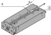
e) Offset the proximity
sensor 8 within its
operating path (b) by 6 mm.

f) Rotate the proximity
sensor 8 by 180°.
g) Select another permissible proximity sensor
(→ www.festo.com/catalogue)
- As required, cover the sensor slots with a slot cover ABP 9 and use them to fix the cables into place (→ More detailed information).
9 Stroke adjustment
9a. For guide units 2 through 4 (no metallic stop)

• Vent the guide units 2 through 4.
→ Note
To avoid the unintentional loosening of the piston rod:
- When loosening and tightening the lock nut (F), counterhold the stop nut (G).
Retracted end position (EJ)
| Loosen the lock nut (D).Adjust the stop rod (Y) with the internal hexagon socket (E).Shorten the stroke by a maximum of 10 mm. | Loosen the lock nut (F).Adjust the stop nut (G).Shorten the stroke by a maximum of 10 mm. |
| Tighten the lock nut (D). Observe the tightening torque M_M1 (→ Table). | Tighten the lock nut (F). Observe the tightening torque M_M2 (→ Table). |
- Vent the guide units 2 through 4
• Start the test run. Check the set stroke.
5) Tolerance for tightening torques M_A with no indication of tolerance: ± 20%
9b. For guide unit 5 (metallic stop)
DEM-...-B-YSRW
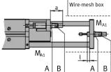
- Vent the guide unit 5.
→ Note
• To reduce the shortening of the stroke dimension a by a maximum of 10 mm
and enlarge it by dimension I by a maximum of 10 mm (→ Section 11).
- Do not exceed fall short of dimension a/l since the shock absorber
performance is otherwise strongly reduced.
- Adjust the shock absorber (B) to dimension a/l as follows:
Retracted end position

| Loosen the lock nut (A)/screw (C).Adjust the shock absorber (B).Observe dimension a. Shortened the factory-set stroke by a maximum of 10 mm (→ Table). | Loosen the lock nut (A)Adjust the shock absorber (B).Observe dimension l. Increase the factory-set stroke by a maximum of 10 mm (→ Table). |
| Tighten the lock nut (A)/screw (C).Observe the tightening torque M_A1 (→ Table). | Tighten the lock nut (A). Observe the tightening torque M_A2 (→ Table). |
- Vent the guide unit 5.
• Start the test run. Check the set stroke.
10. Maintenance and care
10a. In case of guide unit 5
During operation, the viscosity of the hydraulic oil reduces due to friction heat.
→ Shock absorber reset times become shorter (hard knocking).
At low temperatures around 0°C, the viscosity of the hydraulic oil rises.
→ Shock absorber reset times become longer.
The moving mass should always reach the end position safely, but not knock hard against it.
• The shock absorbers should be replaced when their functioning / shock-
absorbing performance is no longer ensured due to excessive wear.
- Check the cushioning regularly for the following signs of wear:
– Oil leakage
– Hard knocking
- Stop rod remains in retracted end position / moves slowly from end
position
• The following environmental conditions shorten the test intervals:
– High thermal stress
– Severe accumulation of dirt
– Proximity of grease-dissolving liquids or vapours.
• Exchange the shock absorber (B) after 10 million strokes (→ Section 9b).
- Dimensions, widths across flats and tightening torques M_A^5)
| DFM----B | 12/16 | 20 | 25 | 32 | 40 | 50 | 63 | ||
| EJ | D | ⩽≦ | – | 8 | 13 | 13 | 13 | 17 | 17 |
| M_b1 | [Nm] | – | 3 | 7 | 10 | 10 | 24 | 24 | |
| E | ⩽≦ | – | 2.5 | 4 | 4 | 4 | 5 | 5 | |
| AJ | F | ⩽≦ | 10 | 13 | 17 | 17 | 17 | 19 | 19 |
| M_b2 | [Nm] | 1.7 | 3 | 6 | 10 | 10 | 16.5 | 19 | |
| G | ⩽≦ | 17 | 19 | 24 | 30 | 30 | 36 | 36 | |
| YSRW | A | ⩽≦ | – | 15 | 17 | 19 | 27 | 27 | 32 |
| M_b1 | [Nm] | – | 5 | 8 | 20 | 35 | 35 | 55 | |
| B | ⩽≦ | – | 11 | 13 | 15 | 20 | 20 | 24 | |
| C | ⩽≦ | – | 4 | – | |||||
| M_b2 | [Nm] | – | 10 | – | |||||
| a | [mm] | – | 34.10 | 37.1.10 | 48.1.10 | 56.5.10 | 58.5.10 | 74.10 | |
| I | [mm] | – | 4.9.10 | 5.2.10 | 4.7.10 | 3.2.10 | 10.4.10 | 11.2.10 | |
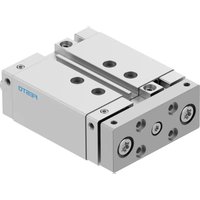


Brand : Festo
Model : DFM-40-B
Category : Industrial pneumatic component