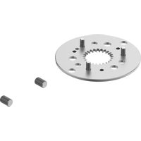
DADM-CK-90-2 - Industrial pneumatic component Festo - Free user manual and instructions
Find the device manual for free DADM-CK-90-2 Festo in PDF.


| Product Type | Double-Acting Cylinder |
| Brand | Festo |
| Model | DADM-CK-90-2 |
| Category | Pneumatic Actuator |
| Stroke Length | 90 mm |
| Piston Diameter | 32 mm (estimated) |
| Operating Pressure | 2 to 10 bar |
| Operating Temperature | -20°C to +60°C |
| Material | Aluminum, Stainless Steel |
| Weight | Approx. 1.2 kg |
| Dimensions (L x W x H) | 250 mm x 40 mm x 40 mm (est.) |
| Connection Type | G1/8 or G1/4 (depending on variant) |
| Mounting Position | Any |
| Operating Medium | Compressed air, filtered and lubricated |
| Functions | Linear motion with cushioning |
| Maintenance | Regular inspection of seals and lubrication |
| Cleaning | Wipe with mild detergent; avoid solvents |
| Safety Precautions | Depressurize before maintenance; avoid exceeding max pressure |
| Spare Parts | Seal kits, piston rods, cushioning rings |
| Repairability | Modular design; replaceable seals |
| Certifications | CE, RoHS |
| Warranty | 2 years (typical) |
| Standards | ISO 6432, VDMA 24562 |
Frequently Asked Questions - DADM-CK-90-2 Festo
User questions about DADM-CK-90-2 Festo
0 question about this device. Answer the ones you know or ask your own.
Ask a new question about this device
Download the instructions for your Industrial pneumatic component in PDF format for free! Find your manual DADM-CK-90-2 - Festo and take your electronic device back in hand. On this page are published all the documents necessary for the use of your device. DADM-CK-90-2 by Festo.
USER MANUAL DADM-CK-90-2 Festo
Assembly instructions (Original: de)
8059334
1604c [805933]
FESTO
Festo SE & Co. KG
m = 311
73726 Essleng
German
+49713670 www.bertc.com
Indexing conversion kit
DADM-CK
5. Mounting
5a. Disassembly of the rotary table

- Mark the rotary table 7 and
the clamping ring 8 at the
notch (B) that corresponds
to the countersink of the
screw 9.
• Untighten screw [9].
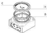
- Turn open the clamping
ring with the help of
2 cylindrical dowel
pins (C)
izes for cylindrical dose
ins (L):
HTG-65: 2 x 2mb
H10-90 = -2A
Remove the
Bullies (3).
From the rotary table [7]
of 7 seconds (5)
head for screen (E)
HTC-651-90: MA
HTG-14D-M6
HT6-220: M8
- Turn the rotating plate 7.
1. Parts lists
1a. Parts list DADM-CK-65/-90
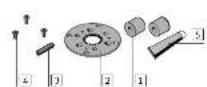
Spacing bolt
2 Index plate
1 Stop bolt
4 Screw
Special grease
LUB-E1
(free of silicone)
1b. Parts list DADM-CK-140/-220
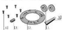
: Spacing bolt
2 Index plate
3 Stop bolt
4 Screw
Special grease
LOB-E1
(free of silicone)
1c. Not in scope of delivery

Rotary indexing
table DHTG
7 Rotating plate
8 Clamping ring
9 Screw
(2x)
(1x)
(1x)
[3x]
(1x)
[Non-Text]
[Non-Text]
[Non-Text]
(2x)
(12)
(1)(1)
[03]
(13)
[Non-Text]
[Non-Text]
[1z]
(1) 特征
(1x)
(1x)
(1x)

- Pull tax return table
on and on with the help
of 7 seconds (5)
Thread for screen (E)
DHTG-651-90: MA
DHTG-14D-M6
DHTG-220: M8
- Turn the rotating plate 7.
5b. Assembly of the index plate 4.
![Unscrew screws (F). Tightens the screws (F) in the threads (G). Force away the index plate (H) from the rotating plate [7] by means of the screws (I). Position the index plate [2] on the rotating plate [7] Fasten the index plate [2] with the screws [4] Observe the index holes (I) Turn the rotating plate [7]](/content/2026/05/1091136/images/c9a5f90175d0cc2fb4422844271de8d58fdd0780ef33393b4199d98df7074e47.jpg)
2. Intended use
indexing conversion kit DADM-CK
Conversion of the rotary indexing table 5 to a different spacing.
3. Safety instructions and notes on mounting
- Switch off compressed air before mounting work.
• Exhausting rotary indexing table 5
• Observe tightening torques (→ Section 6).
i Information copies
Applicable documents → www.festo.com/sp
→ Rotary indexing table DHTG operating instructions
→ Assembly instructions for energy throughfeed DHTG-P4
4. Preparations for mounting
- Disassemble the energy throughfeed DIITG-P4 (→ applicable documents).
- Grease all movable parts of the indexing conversion kit using the
grease 5
The rotary table 2 must be turning freely.
To unlock:
- Pressurise port "A" with minimum 4 bar.
5c. Assembly of the rotary table 7

1) With DADM-CK-5-2, DADM-CK-90-1, DADM-CK-340-3, DADM-CK-120-3 there are no starting basis included in the scope of delivery ( Section 7).
3) The cylindrical correlating (C) can not be included in the space of delivery.
^13 The screws (E) are not included in the scope of delivery.
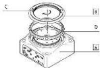
- Place the ball bearing
cage (D) in the rotary index
ing table 6.
- Tighten the clamping ring [8]
by means of the cylindrical
dowel pins (C)
- Unlighten and remove the
Lynmical Bowel pins (C).

Check: The marks on the
rotating plate 7] and on the
clamping ring match at
the notch (B)
- Tighten screw 9.
5d. Assembly of spacing bolt 1

- Turn open the clamping
component (K) by 1 turn.
- Unscrew the stop screw (L).
- Unscrew flow control
valve (M).
- Unlighten screw (N).
- Carefully remove the sub-
base (0). Make sure not
lose the compression
spring (P) and the seals.
- Uncrew screws (Q).
- Carefully remove the stop
plate (R). Make sure not to
lose the seals.

Remove the split pins (S)
from the hole to their left.

Push the existing spot
pils into the notes an
the belt (→ section 3). With the eplitz pine inerm
with the split (plus)
□
- POSITION THE CO-MPRESSION spring © in the hole of the
spring (1) in the role of the
Without the split pins in
A. 10. April 2014
- Remove the compression
spine (P) ^4
Check: Correct fit of the seals.
- Faster the sub-base (O) us-
ing screws (N)
^a1 Without the split pin mounted, no counter pressure is acting on the compression spring (0), which causes function failure of the rotary indexing table.

- Screw in and tighten the
throttle valve (A).
Check: Correct (it of the seals.
- Fasten the stop plate (R) us
ing the screws (Q).
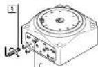
- Screw in the existing stop
bolt 3 (→ Section 7).
Check: The required cushion
ing is achieved.
• Tighten the clamping com-
ponent (K).
- Pressurise the rotary indexing table 6
The rotary table must not turn freely.
To lock:
- Pressurise port "B" with minimum 4 bar.
If the rotary table 7 is still rotating freely:
- Manually turn the rotary table 7 until the index bolts (i) engage.
- Screw sizes and tightening torques M. ^5
| DADM-CK- | 65 | 90 | 140 | |
| (K) Clamping component | ≤2 | 2.5 4 | ||
| [Nm] | 0.8 2.5 | |||
| (K) Flow control value | GRLA-M5-B GRLA-C18 | |||
| [Nm] | 1.5 5.5 | |||
| (N) Screw | Mx26 | Mx26 Mx25 | ||
| 3 | 10 | |||
| (0) Screw | Mx36 | Mx36 Mx36 Mx20 | ||
| 1.5 3 6 | ||||
| 4 Screw | Mx8 Mx12 Mx36 Mx18 | |||
| 2 6 | 7 | |||
| √ Screw | Mx96 | |||
| [Nm] 0.6 | ||||
- Lengths of the split pins 1 and stop bolts 3 ^1)
| DADM-CX- | 65 | 90 | 140 | 220 | ||
| Spacing | Pin | |||||
| 7 | [mm] | - | - | - | - | |
| 3 | (mm) | 12 | 12 | - | - | |
| 5 | 1 | [mm] | 11.31 | 15.71 | - | - |
| 3 | (mm) | 23.3 | 28 | 4 | 19 | |
| 4 | [mm] | 16.96 | 23.56 | 12.57 | 25.13 | |
| 3 | (mm) | 29 | 35.5 | 26.5 | 44.1 | |
| 6 | [mm] | 12.62 | 31.42 | 25.23 | 50.27 | |
| 3 | (mm) | 34.6 | 63.5 | 32 | 69.3 | |
| 8 | [mm] | 75.45 | 35.34 | 71.67 | 62.83 | |
| 3 | (mm) | 37.5 | 47.5 | 45.5 | 81.8 | |
| 12 | [mm] | 28.27 | 39.27 | 37.7 | 75.4 | |
| 3 | (mm) | 60.3 | 51.5 | 51.5 | 94.4 | |
| 24 | [mm] | 11.1 | 43.2 | 42.98 | 87.97 | |
| 3 | (mm) | 45 | 55.5 | 58 | 107 | |
8. Prior to commissioning
Cushioning setting and commissioning (→ applicable document).
^42 Tolerances in tightening resources (i.e. without tolerance details
t_A > 0.6 1, 3m × 10%
N_a × 1. No: ±20%
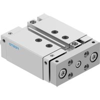


Brand : Festo
Model : DADM-CK-90-2
Category : Industrial pneumatic component