
AP4-TY11 - Receiver PAC - Free user manual and instructions
Find the device manual for free AP4-TY11 PAC in PDF.


| Product Type | Car Stereo Receiver |
| Brand | PAC |
| Model | AP4-TY11 |
| Dimensions (W x H x D) | 178 mm x 50 mm x 160 mm |
| Weight | 1.2 kg |
| Power Supply | 12V DC (negative ground) |
| Power Output | 4 x 50 Watts RMS |
| Radio Bands | AM/FM, RDS |
| Bluetooth | Yes, hands-free calling and audio streaming |
| USB Input | Yes, front USB port for MP3/WMA playback |
| AUX Input | Yes, 3.5 mm front auxiliary input |
| Display | LCD dot matrix, multi-color illumination |
| Supported Audio Formats | MP3, WMA, WAV, FLAC |
| Equalizer | 7-band graphic equalizer with presets |
| Steering Wheel Control | Compatible with PAC SWI interface (sold separately) |
| Rear Camera Input | Yes, RCA input with auto-switch |
| Additional Features | Bluetooth A2DP, ID3 tag display, clock, dimmer |
| Maintenance and Cleaning | Clean with soft dry cloth; avoid liquids |
| Safety | Fuse protected (15A mini blade). Disconnect battery before installation |
| Spare Parts and Repairability | Contact PAC support for replacement fuses and service |
Frequently Asked Questions - AP4-TY11 PAC
User questions about AP4-TY11 PAC
0 question about this device. Answer the ones you know or ask your own.
Ask a new question about this device
Download the instructions for your Receiver in PDF format for free! Find your manual AP4-TY11 - PAC and take your electronic device back in hand. On this page are published all the documents necessary for the use of your device. AP4-TY11 by PAC.
USER MANUAL AP4-TY11 PAC
Introduction and Features
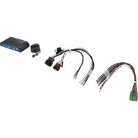
The AP4-TY11 provides a 6-channel pre-amp output for use with aftermarket audio equipment. Using the full range, fixed level head unit output, in conjunction with data bus messages, the AP4-TY11 delivers a variable 5v RMS pre-amp output with fading, balance, equalization, and level control capabilities. The module also retains audio from other vehicle features such as factory navigation prompts, Bluetooth and Voice Activation. An accessory controlled remote amplifier turn on wire is also provided by the AP4-TY11. When used in conjunction with the APA-TOS1 (sold separately), the module can provide a variable 2-channel fiber optic digital audio output (TOSLINK).
Important Notes
- Only compatible in vehicles equipped with a data bus controlled premium sound system. To verify compatibility in Toyota, look for a JBL logo on the radio. In Lexus applications, most compatible radios will have a factory subwoofer or center channel. RX Series Lexus are always amplified regardless if they do or do not have a center channel or subwoofer. Always check PAC-audio.com for radio specific compatibility notes based on the year, make and model of the vehicle.
- Voice activation / navigation prompt audio requires the AP4-TY11 harness to be connected for the proper configuration for the vehicle. See the Vehicle Connections Chart starting on page 2 for details.
- The factory radio's speed controlled volume, DSP, and surround sound mode are not supported by the AP4 outputs.
- The factory amplifier must remain connected, and in the vehicle after the AmpPRO has been installed.
- Prior to testing, cycle the ignition off and back on again to properly initiate the AP4-TY11.
- The AP4-TY11 beep volume and minimum volume levels are set to 0 dB by default. If you are happy with this level in your particular application, additional adjustment is not required. Please refer to the Setup and Configuration section on page 9 for more details.
- The remote output is rated at 2A of current. If more current is needed, an external relay must be used.
- Channels 5 and 6 are non-fading outputs. The output level of channels 5 and 6 can be controlled using the supplied level control knob.
- The level control knob must be connected in order to manually adjust the beep volume and minimum volume settings.
- Due to variations in output levels between various OEM radios and even between radio modes, the AP4-TY11 output voltage may vary from the selected 5 volt (or 4 volt when DIP switch 2 is down) output.
- Toyota Safety Connect and Lexus Enform (SOS) can easily be retained. See the Tech Brief "AP4-TY SOS Retention" at PAC-audio.com for detailed instructions.
Wiring Connection Chart

flowchart
graph TD
    A["AP4-TY11-HAR"] -->|To Radio| B["To Amp PRO*"]
    A -->|To Radio| C["To Radio"]
    A -->|To Radio| D["To Vehicle Harness"]
    A -->|To Radio| E["Remote Turn On Output (2A Max)"]
    A -->|To Radio| F["Mute Input From Navigation"]
    A -->|To Radio| G["Mute Input From Telematics"]
    A --> H["Non-Fading Level Control Knob"]
    H --> I["Non-Fading RearFront"]
    I --> J["To Aftermarket Amplifier"]
Vehicle Connections Chart
The connections chart provides the information necessary to retain the voice prompts and navigation audio along with details of where to find the factory amplifier, and in some cases, location of the factory navigation module. In vehicles with navigation and / or a voice button on the steering wheel, locate your vehicle on this chart to determine which config you will use. If the vehicle does not have the voice button on the steering wheel and it does not have navigation, this information will not pertain to the installation.
Use the chart to determine which Configuration to use, and the location of the amplifier and navigation module (when applicable). Under the "Config Type" column, if it is listed as "A" it is config type A, "B" is config type "B" and Config type C is listed as the 3 possible versions. "C v1" is config type C version 1, "C v2" is config. type C version 2, and "C v3" is config C version 3. See the appropriate section covered on pages 5 thru 8 regarding the connections covered in the chart. If there is an N / A listed for the vehicle, the information in that column does not pertain to your vehicle. The "Nav Input Audio" and "Nav Output Audio" information describes the wiring and connector found at the navigation module.
Toyota
| Model Years | Config Type | OEM Amp Location | Nav Module Location | Nav Input Audio | Nav Output Audio | Audio / Audio | N/A |
| 4Runner 20 | 03 - 2005 * C v3 | Behind Right | Rear SidePanel in Rear Cargo Area | Over Right Rear Tire WellIn Rear Cargo Area | 18 Pin ConnectorPin 1 (+) Light GreenPin 10 (-) Blue | 18 Pin ConnectorPin 2 (+) Light GreenPin 11 (-) Blue | |
| 4Runner | 2006 - 2013 A | Behind Right | Rear SidePanel in Rear Cargo Area | N/A | N/A | N/A | |
| Avalon | 2005 - 2007 | C v3 | Under Front Right Seat | Left Side of LuggageCompartment | 18 Pin ConnectorPin 1 (+) GrayPin 10 (-) Yellow | 18 Pin ConnectorPin 2 (+) PinkPin 11 (-) Violet | |
| Avalon | 2008 - 2010 | Non Nav: ANav: C v3 | Under Front Right Seat | Left Side of LuggageCompartment | 18 Pin ConnectorPin 1 (+) GrayPin 10 (-) Yellow | 18 Pin ConnectorPin 2 (+) PinkPin 11 (-) Violet | |
| Avalon | 2011 - 2012 | A | Under Front Right Seat | N/A | N/A | N/A | |
| Avalon | 2013 - 2014 | B | Under Front Left Seat | N/A | N/A | N/A | |
| Camry | 2007 - 2011 | A | Under Front Right Seat | N/A | N/A | N/A | |
| Camry | 2012 - 2014 | B | Under Front Left Seat | N/A | N/A | N/A | |
| Corolla | 2005 - 2008 | N/A | Under Front Right Seat | N/A | N/A | N/A | |
| Corolla | 2009 - 2011 | A | Under Front Right Seat | N/A | N/A | N/A | |
| FJ Cruiser 20 | 11 - 2014 | A Behind Right | Rear SidePanel in Rear Cargo Area | N/A | N/A | N/A | |
| Highlander | 2008 - 2010 | A | Under Front Right Seat | N/A | N/A | N/A | |
| Highlander | 2011 - 2013 ** | Radio andDisplay: BAll Others: A | Under Front Right Seat | N/A | N/A | N/A | |
| Prius | 2004 - 2005 | C v1 | Under Front Right Seat | N/A | N/A | Pin 22 (+) WhitePin 21 (-) Black | |
| Prius | 2006- 2009 | C v2 | Under Front Right Seat | N/A | N/A | Pin 25 (+) GreenPin 26 (-) Red | |
| Prius | 2010 - 2011 | A | Under Front Right Seat | N/A | N/A | N/A | |
| Prius | 2012 - 2015 | B | Under Front Right Seat | N/A | N/A | N/A | |
| Rav4 2004 | - 2006 N/A | Behind Right | Rear SidePanel in Rear Cargo Area | N/A | N/A | N/A | |
Vehicle Connections Chart (cont.)
Toyota (cont.)
| ModelYears | Config Type | OEM Amp Location | Nav Module Location | Nav Input Audio | Nav Output Audio | New Output Audio |
| Rav4 2007 | - 2012 A Behind | Right Rear Side | Panel in Rear Cargo Area | N/AN/AN/A | ||
| Rav4 2018 | B | Behind Right Rear Side | Panel in Rear Cargo Area | N/AN/AN/A | ||
| Sequioa | 2005 - 2013 | A | Under Front Right Seat | N/A | N/A | N/A |
| Sienna | 2004 | C v3 | Right Side of Dash Behind Glovebox | Under Front Right Seat 18 | Pin Connector Pin 1 (+) Green / White Pin 10 (-) Brown | 18 Pin Connector Pin 2 (+) Pink Pin 11 (-) Violet |
| Sienna | 2005 - 2010 A | Right Side of Dash Behind Glovebox | N/AN/AN/A | |||
| Sienna | 2011 - 2014 | A | Under Front Right Seat | N/A | N/A | N/A |
| Tacoma | 2005 - 2008 | N/A | Back Wall Right Side | N/A | N/A | N/A |
| Tacoma | 2009 - 2011 | A | Back Wall Right Side | N/A | N/A | N/A |
| Tacoma | 2012 - 2013 | B | Back Wall Right Side | N/A | N/A | N/A |
| Tundra | 2009 - 2012 | A | Built Into Rear Seat Back | N/A | N/A | N/A |
| Tundra | 2007 - 2013 | A | Under Front Right Seat | N/A | N/A | N/A |
| Venza | 2009 - 2012 | A | Under Front Left Seat | N/A | N/A | N/A |
| Venza | 2013 | B | Under Front Left Seat | N/A | N/A | N/A |
* VR / Nav Trigger wire is in the 18-Pin Navigation connector in Pin 15 and is Violet / White.
** If the radio only has provisions for one of the 20-Pin connectors from the AP4-TY11 harness, it is "Config A", if it has provisions for both 20-Pin connectors, it is "Config B".
Lexus
| Model | Years | Config Type | OEM Amp Location | Nav Module Location | Nav Input Audio | Nav Output Audio |
| CT200h | 2011 - 2013 | A | Under Front Right Seat | N/A | N/A | N/A |
| ES300 | 2002 - 2003* C v3 | Behind Right Side Panel of Luggage Compartment | Left Side of Luggage Compartment | 18 Pin Connector Pin 1 (+) Pink Pin 10 (-) Violet | 18 Pin Connector Pin 2 (+) Pink Pin 11 (-) Violet | |
| ES300h | 2013 - 2014** | Multi-Media Radio: B Other: A | Under Front Left Seat | N/AN/A | N/A | |
| ES330 | 2004 - 2006 | A | Behind Right Side Panel of Luggage Compartment | N/AN/A | N/A | |
| ES350 | 2007 - 2009** | Non Nav: A Nav: C v1 | Behind Right Side Panel of Luggage Compartment | N/AN/A | Pin 22 (+) Yellow | Pin 21 (-) Brown |
| ES350 | 2010 - 2012 | A | Behind Right Side Panel of Luggage Compartment | N/AN/A | N/A | |
| ES350 | 2013 - 2014** | Multi-Media Radio: B Other: A | Behind Right Side Panel of Luggage Compartment | N/AN/A | N/A |
Vehicle Connections Chart (cont.)
Lexus (cont.)
| Model Years | Config Type | OEM Amp Location | Nav Module Location | Nav Input Audio Nav Output | Audio | Inner Output |
| GX460 20 | 08 - 2009 C v1 | Behind Right Side Panel of Luggage Compartment | N / A N / A Pin 22 | (+) Yellow | Pin 21 (-) Brown | |
| GX460 | 2010 - 2013 | A | Under Front Right Seat | N / A | N / A | N / A |
| GX470 | 2004 - 2006* | C v3 | Under Front Left Seat | Under Front Right Seat | 18 Pin Connector Pin 1 (+) Blue Pin 10 (-) Light Green | 18 Pin Connector Pin 2 (+) Light Green Pin 11 (-) Blue |
| GX470 | 2007 - 2009 | C v2 | Under Front Left Seat | N / A | N / A | Pin 25 (+) Blue Pin 26 (-) Pink |
| HS250h | 2010 - 2012 | A | Under Front Right Seat | N / A | N / A | N / A |
| IS250 IS350 | 2006 - 2009 C v1 | Behind Right Side Panel of Luggage Compartment | N / A N / A Pin 22 | (+) Yellow | Pin 21 (-) Brown | |
| IS250 IS350 | 2010 - 2013 | A | Behind Right Side Panel of Luggage Compartment | N / A N / A | N / A | |
| IS250C IS350C | 2010 - 2015 | A | Behind Right Side Panel of Luggage Compartment | N / A N / A | N / A | |
| IS-F | 2008 - 2009 C v1 | Behind Right Side Panel of Luggage Compartment | N / A N / A Pin 22 | (+) Yellow | Pin 21 (-) Brown | |
| IS-F | 2010 - 2014 | A | Behind Right Side Panel of Luggage Compartment | N / A N / A | N / A | |
| RX330 20 | 04 - 2006 C v3 | Under | Floor Right Front Side of Luggage Compartment | Right Rear Side of Luggage Compartment | 18 Pin Connector Pin 1 (+) Yellow Pin 10 (-) Light Green | 18 Pin Connector Pin 2 (+) Brown Pin 11 (-) Black |
| RX350 20 | 07 - 2009 C v2 | Under | Floor Right Front Side of Luggage Compartment | N / A N / A | Pin 25 (+) Red | Pin 26 (-) Green |
| RX350 20 | 10 - 2012 | A | Under Floor Right Front Side of Luggage Compartment | N / A N / A | N / A | |
| RX350 | 2013 - 2015** | Radio & Display: B Others: A | Under Floor Right Front Side of Luggage Compartment | N / A N / A | N / A | |
| RX400h | 2007 - 2008 C v2 | Under Floor Right Front Side of Luggage Compartment | N / A N / A | Pin 25 (+) Red | Pin 26 (-) Green | |
| RX450h | 2010 - 2015** | Radio & Display: B Others: A | Under Floor Right Front Side of Luggage Compartment | N / A N / A | N / A | |
* VR / Nav Trigger wire is in the 18-Pin Navigation connector in Pin 15 and is Pink in the GX470 and Violet in the RX330
** If the radio only has provisions for one of the 20-pin connectors from the AP4-TY11 harness, it is "Config A", if it has provisions for both 20-pin connectors, it is "Config B".
Module Layout


Installation

Set DIP switches to the ON position to activate the corresponding features. Set DIP switches to the OFF position for any features that are not desired.

| Two Channel Mode | 5v / 4v Preout Not Used | Not Used | |
| 1 2 3 4 |
- Find your vehicle on the vehicle config chart (pages 2 - 4) to determine which config you will use.
- Remove factory radio.
- Disconnect the primary 20-pin harness and the secondary 20-pin harness (when available) from the radio.
- Connect AmpPRO harnesses to vehicle harnesses.
- Connect AmpPRO harnesses to factory radio.
- Make appropriate "A", "B" or "C" Voice / Nav audio connections (see next section for detailed information).
- Set any feature DIP switches that apply to your install (per the diagram above).
a. DIP switch 1 is used for two channel mode. In this mode, both the TOSLINK and front RCA outputs (1 and 2) become non-fading outputs.
b. Set DIP switch 2 on (down) to lower the RCA output voltage to 4v. Leave DIP switch 2 off (up) to keep the RCA output voltage at 5v. See troubleshooting section on page 11 for more details.
c. DIP switches 3 and 4 are not used and should remain up.
- If you are using the APA-TOS1 (sold separately) refer to the instructions included with that product for its installation.
- Connect the AmpPRO harness to the module.
- Connect the level control knob to the module and install in an accessible location.
- Connect the signal cables and remote input from the aftermarket amplifier.
- The Yellow / Black "Mute Input from Telematics" wire will only be used in conjunction with the Safety Connect / Lexus Enform (SOS) Retention. See the Tech Brief "AP4-TY SOS Retention" at PAC-audio.com for detailed instructions.
Voice / Nav Audio Connections
Toyota / Lexus voice activation audio and navigation audio is located in different harnesses and different locations depending on the year, make and model of the vehicle. If the radio has navigation or the steering wheel has a voice button (or both), to retain this audio it is necessary to make some additional connections when using aftermarket amplifiers to power the front speakers. There are 3 possible configurations. To determine the configuration to use, refer to the vehicle chart on pages 2 - 4.
Configuration A:
The voice / navigation positive and negative audio leads are present in the secondary 20-pin connector in pins 11 and 12 of the factory radio connector. This can be verified by plugging the secondary 20-pin connector (see Config A diagram on page 6) from the radio harness into the AP4-TY11 secondary 20-pin connector then looking for wires in pin positions 11 and 12 on the factory harness side. Pins 11 and 12 will be the same pins as the White / Red and White / Blue wires on the AP4-TY11 side of the harness. If there are no wires in these pin locations on the factory harness, Config A is not the correct one for the vehicle.
Connect the 2-pin connector labeled "A" to the 2-pin connector labeled "To Amp PRO" (See Config A diagram on page 6). The Brown "Mute Input from Navigation" wire from the AP4-TY11 harness will not be used for this configuration.
Voice / Nav Audio Connections (cont.)


Configuration B:
The voice / navigation positive and negative audio leads are present in the primary 20-pin connector in pins 16 and 17 of the factory radio connector. Config. B applications will only have provisions for one of the 20-pin connectors at the radio. The additional 20-pin male and female connection will not be used.
Connect the 2-pin connector labeled "B" to the 2-pin connector labeled "To Amp PRO".
The voice / navigation positive and negative audio leads are present in the primary 20-pin connector in pins 16 and 17 of the factory radio connector. This can be verified by plugging the primary 20-pin connector (see Config B diagram above) from the radio harness into the AP4-TY11 primary 20-pin connector then looking for wires in pin positions 16 and 17 on the factory harness side. Pins 16 and 17 will be the same pins that you find the White / Red and White / Blue wires on the AP4-TY11 side of the harness. If there are no wires in these pin locations on the factory harness, Config B is not the correct one for the vehicle.
Connect the 2-pin connector labeled "B" to the 2-pin connector labeled "To Amp PRO" (See Config B diagram above). The Brown "Mute Input from Navigation" wire from the AP4-TY11 harness will not be used for this configuration.
Configuration C:
This configuration requires manually wiring the harness with connector labeled "C" into either the Multi-Display (separate
radio / HVAC display screen) harness or the outputs at the navigation module depending on the year, make and model of the vehicle (refer to the vehicle chart on pages 2 - 4). For this reason, we have divided Config C into 3 different versions.
- Config C, Version 1: The voice / navigation audio leads are present in the 28-pin connector located behind the Multi-Display. Connect the loose 2 pin harness labeled "C" to the 2 pin connector labeled "To Amp PRO". Next, locate the 28-pin Multi-Display connector (at the back of the separate radio / HVAC display screen). Connect the White / Blue wire from the "C" harness into the wire that is in pin 21 and connect the White / Red wire from the "C" harness to the wire that is in pin 22 of the 28-pin Multi-Display connector. Refer to the Vehicle Connections Chart starting on page 2 for specific wire color information. The Brown "Mute Input from Navigation" wire from the AP4-TY11 harness will not be used for this configuration.

Voice / Nav Audio Connections (cont.)
- Config C, Version 2: The voice / navigation audio leads are present in the 40-pin connector located behind the Multi-Display. Connect the loose 2-pin harness labeled "C" to the 2-pin connector labeled "To Amp PRO". Next, locate the 40-pin Multi-Display connector (at the back of the separate radio / HVAC display screen). Connect the White / Blue wire from the "C" harness into the wire that is in pin 26 and connect the White / Red wire from the "C" harness to the wire that is in pin 25 of the 40-pin Multi-Display connector. Refer to the Vehicle Connections Chart starting on page 5 for specific wire color information. The Brown "Mute Input from Navigation" wire from the AP4-TY11 harness will not be used for this configuration.

- Config C, Version 3: The voice / navigation audio leads are only present at the outputs of the navigation module. There are 3 different methods for connections under version 3. Use the information provided to determine the best option for your application.
Method 1 is used when you are only adding an aftermarket amplifier for subwoofers, or when wiring an aftermarket amplifier to the front speaker outputs of the factory amplifier, rather than running new speaker wires from the aftermarket amp straight to the front speakers. When running an aftermarket amp to the front speaker outputs of the factory amplifier, the left front speaker output of the aftermarket amplifier passes through the navigation module. It is recommended to use an amplifier that provides 150 watts or less so that the factory navigation module is not damaged due to excessive heat. If the front speaker output is in excess of 150 watts, use Method 2 or Method 3 instead.
Method 1 may require running a wire from the AP4-TY11 harness brown wire labeled "Mute Input From Navigation" to a wire at the navigation module. Most applications do not require this connection. Next, cut the front speaker outputs (and rear speaker outputs if applicable) to the appropriate speaker wire outputs at the factory amplifier, and insulate the side that goes towards the amplifier (these will not be used). Wire the aftermarket amplifier outputs to the appropriate remaining speaker wires. Refer to the Vehicle Connections Chart section starting on page 5 for information regarding where the navigation module is located and where to connect the Brown wire.
- Config C, Version 3:
Method 2 is used to pass the voice prompts and navigation audio through the AP4-TY11 instead of through the navigation module when using an aftermarket amplifier on the front speakers. If the Vehicle Connections Chart (starting on page 5) does not indicate that there is a VR / Nav Trigger wire, Method 2 is not an option (use Method 3). If the aftermarket amplifier output is less than 150 watts on the front speakers, Method 1 is also an option.
Method 2 requires running a wire from the AP4-TY11 harness brown wire labeled "Mute Input From Navigation" to a wire at the navigation module. It is also necessary to run a speaker wire from the White / Red (+) and White / Blue (-) wires on the loose AP4-TY11 harness labeled "C" to the navigation audio outputs located at the navigation module.

flowchart
graph TD
    A["Config C\nVersion 3 Method 2"] --> B["To Amp PRO"]
    B --> C["Wire to navigation module output\n(per vehicle chart)"]
    C --> D["Factory Nav Module"]
    D --> E["VR / Nav Trigger Ground Output"]
    E --> F["Factory Amplifier"]
    F --> G["Right Rear\nSpeaker Outputs"]
    F --> H["Left Rear\nSpeaker Outputs"]
    F --> I["Right Front\nSpeaker Outputs"]
    F --> J["Left Front\nSpeaker Outputs"]
    G --> K["Cut and Insulate Speaker Wires"]
    H --> K
    I --> K
    J --> K
    D --> L["To VR / Nav Trigger"]
    L --> M["Mute Input From Navigation"]
    M --> N["Factory Amplifier"]
Voice / Nav Audio Connections (cont.)
- Config C, Version 3, Method 2 (cont.):
Next, plug the 2-pin connector on the "C" harness into the 2-pin receptacle on the AP4-TY11 harness labeled "To Amp PRO". Refer to the "Vehicle Connections Chart" section starting on page 5 for information regarding where the navigation module is located and where to connect the Brown wire. See the Config C, Version 3, Method 2 diagram on page 7.
- Config C, Version 3:
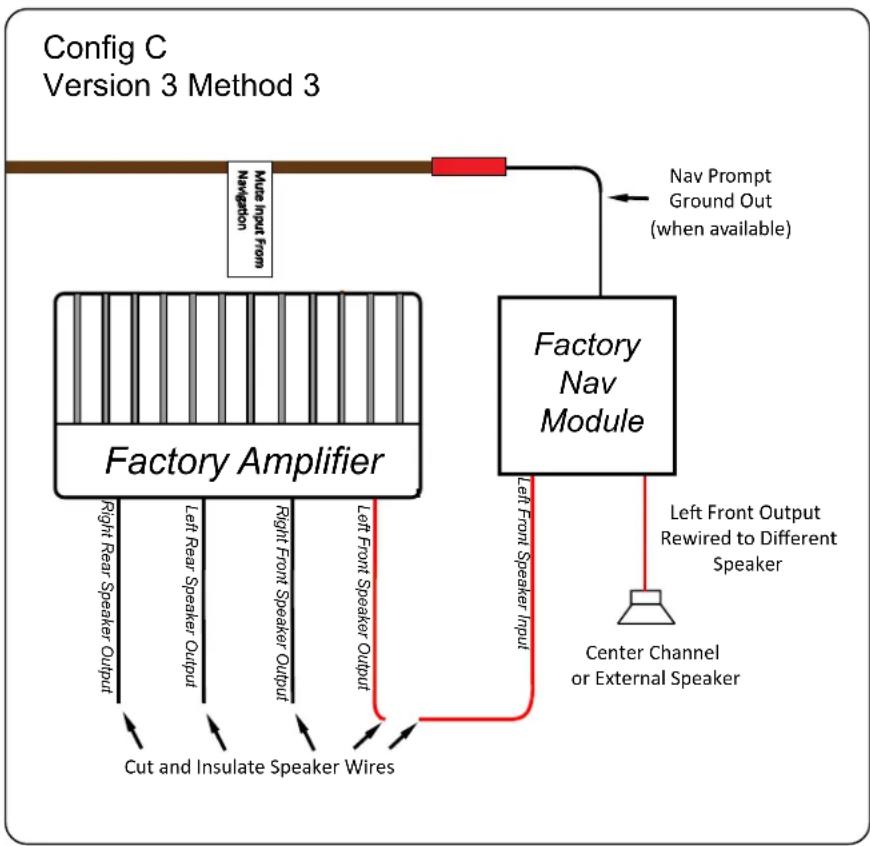
Method 3 bypasses the factory navigation module and uses an external speaker (not supplied) to provide the voice prompts and navigation audio.
Method 3 may require running a wire from the AP4-TY11 harness brown wire labeled "Mute Input From Navigation" to a wire at the navigation module. It also requires cutting the audio input and output wires at the navigation module and insulating the input wires that lead back to the factory amp (to prevent shorting them out).
Extend a speaker wire from the navigation audio output wires to an
flowchart
graph TD
    A["Config C\nVersion 3 Method 3"] --> B["Factory Amplifier"]
    B --> C["Factory Nav Module"]
    C --> D["Nav Prompt Ground Out\n(when available)"]
    D --> E["Main Input From Navigation"]
    B --> F["Right Rear Speaker Output"]
    B --> G["Left Rear Speaker Output"]
    B --> H["Right Front Speaker Output"]
    B --> I["Left Front Speaker Output"]
    B --> J["Cut and Insulate Speaker Wires"]
    C --> K["Left Front Speaker Input"]
    C --> L["Center Channel or External Speaker"]
    C --> M["Left Front Output Rewired to Different Speaker"]
external 4 ohm speaker and hide it in a place where it will be audible (commonly under the dashboard on the driver's side of the vehicle). If the vehicle has a center channel speaker that is no longer being used, it is possible to run the speaker wires to this speaker rather than adding an additional speaker. Refer to the "Vehicle Connections Chart" section below for information regarding where the navigation module is located and where to connect the Brown wire. Applications that use the Brown wire will be marked with a single asterisk (*) and the wiring information will be given below the vehicle chart. For this method, none of the White / Red and White / Blue connectors ("To Amp PRO", "A", "B" or "C") will be used. See the Config C, Version 3, Method 3 diagram above.
Setup and Configuration
- Turn the ignition on. LED 1 on the interface will turn on and the +12v remote output will turn on.
- Set the amp gain(s) to the desired level. We recommend using an oscilliscope and test tones to set the amp gain(s). Please refer to the MECP Advanced study guide if you are unfamiliar with this process.
- Check volume, balance, fade and EQ settings.
- If you would like to adjust the minimum volume, do so using the method outlined on the next page. If you are happy with the default level then no further adjustments are required
- If you would like to adjust the radio's beep volume or minimum volume, do so using one of the methods outlined below. If you are happy with the default levels, no adjustments are necessary.
Manually Setting the Radio's Beep Volume
You can manually set the level of the factory radio beeps using the programming button on the side of the interface. If you would like to set the beep volume using the PC app please proceed to the AmpPRO App section.
Setup and Configuration (cont.)
Setting the radio's beep volume using the programming button
- Start with the level control knob turned all the way down (counter-clockwise).
- Press the programming button on the side of the interface.
- LED 1 will turn green and beeps will begin continuously sounding.
- Turn the level control knob clockwise until the desired beep volume level is reached.
- You can now either press the programming button twice or wait ten seconds to exit the settings.
Manually Setting the Minimum Volume
If the minimum volume of the radio (factory radio volume level 1) is too loud, you can manually set the level of the minimum volume using either the programming button on the side of the interface or the factory SWC. If you would like to set the minimum volume using the AmpPRO app, please proceed to the AmpPRO App section.
Setting the minimum volume using the programming button
- Start with the level control knob turned all the way down (counter-clockwise).
- Set the amp gains to the desired level.
- Set the volume on the factory radio to 1.
- Press the programming button on the side of the interface twice.
- LED 1 will turn amber and the chimes will begin sounding every five seconds.
- Turn the level control knob clockwise until the desired minimum volume level is reached.
- You can now either press the programming button once or wait ten seconds to exit the settings.
AmpPRO App
Use of the AmpPRO App allows you to do the following:
- Configure User Interface Options such as:
• Minimum Volume Level
- Enable / Disable factory EQ
- Bass / Mid / Treble boost frequencies and Q factor
- Update Product Firmware
- Read Firmware / Hardware Versions
- You can download the Amp PRO app at: http://pac-audio.com/firmware
PLEASE NOTE: These settings can be adjusted with the module installed in the vehicle, or on the bench. However, it is recommended to make the adjustments with the module installed, and the factory radio on, so that the changes can be heard.
Minimum Volume Level - This allows you to set the
minimum volume level of the factory radio (factory radio volume level 1).
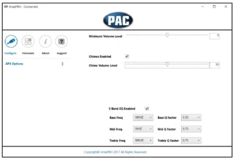
3 Band EQ Enabled - This allows you to enable / disable the 3 band factory EQ.
Bass / Mid / Treble Freq / Q Factor - This allows you to set the center frequency that will be adjusted when setting the 3 band factory EQ, as well as the Q Factor for each frequency. The Q Factor determines how many of the adjacent frequencies will be affected when adjusting the selected frequency. The lower the Q Factor, the more frequencies will be affected.
| Available Frequencies and Q Factors | |||||
| Bass Frequency | 60HZ | 500HZ 7.5KHZ | |||
| 80HZ | 1KHZ 10KHZ | ||||
| Mid-Frequency Treble Frequency | |||||
| 100HZ | 1.5KHZ 12.5KHZ | ||||
| 120HZ | 2.5KHZ 15KHZ | ||||
| Bass Q Factor | 0.50 | 0.75 | 0.75 | ||
| 1.00 | 1.00 | ||||
| Mid-Q Factor | Treble Q Factor | ||||
| 1.50 | 1.25 | 1.25 | |||
| 2.00 | 1.50 | ||||
AmpPRO App (cont.)
Firmware Updates
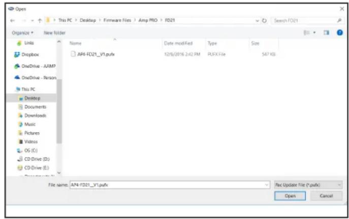
The AmpPRO app will also allow you to update the interface with new firmware as it becomes available. Please visit http://pac-audio.com/firmware to see if there is a firmware update for your interface.
Connect the interface to your PC and select "Firmware", then "Update Firmware". Now select "Select File". Finally, browse to the place where you saved the file and select it. This will begin the updating process. Once finished, disconnect the interface from the PC and resume normal operation.

Restoring Factory Settings
You can restore the interface to factory default settings by pressing and holding the programming button on the side of the module until the status LEDs start blinking red. Once the LEDs start blinking red, release the button.
This reset will restore the following settings to their factory defaults:
- Enable / Disable Factory Chimes
• Minimum volume level - Enable / Disable factory EQ
• Factory EQ frequency
• Factory EQ Q factor
Troubleshooting
- Hiss at high amp gain - Set feature DIP switch 2 to the on (down) position to lower the output voltage of the AP4 to 4v. If you still hear the hiss, lower your amp gains until the hiss is gone.
- Low volume setting on radio is too loud - Set minimum volume using process outlined in Setup and Configuration, or using the AmpPRO application.
- Cannot hear beeps when pressing buttons on the radio - Set the beep volume using process outlined in Setup and Configuration, or using the AmpPRO application. If you still do not hear beeps, check for a beep on off setting in the factory radio menu and be sure that you are using the remote output from the AP4 to turn on your aftermarket amplifier.
- Cannot hear the Voice Activation or Navigation Prompts, verify that the configuration connections are properly connected. See "Voice / Nav Connections" starting on page 2 for details.
- Low volume setting on radio is too loud - Set minimum volume using process outlined in Setup and Configuration, or using
the AmpPRO application.
- Drastic volume difference between radio sources - The radio stores the volume of the radio source from the last time that source was used. Readjust the volume of the individual sources to the same output level.
| LED Legend | ||
| LED 1 | Action / Color | During Normal Operation |
| Solid Red | Module Active | |
| Solid Green | Chime Volume Adjustment Mode | |
| Solid Amber | Minimum Volume Adjustment Mode | |
| Rapid Blink Any Color | DSP Activity | |
| LED2 | Blink Amber | USB Connection Detected |
| Both LEDs | Alternate Blinking Red | Performing Memory Reset |
Technical Bulletin
Overview
Symptom: Symptoms may include the interface not turning on, the factory radio not turning on (AP4-CH41 only), no audio or intermittent audio on one or more channels.
Cause: Pins pulling out of the JST connector that plugs into the AP4 interface resulting in poor, or no connection of some circuits.
Solution: Locate pins that have pulled out of the connector and fully re-insert the pins into the harness.
If a pin has pulled completely out of the harness, see "AP4 Connector Diagrams" starting on page 2 for pinouts of each of the amp pro interfaces to find pin location information.
Inspect The Harness To Identify Pins That May Be Causing Issues
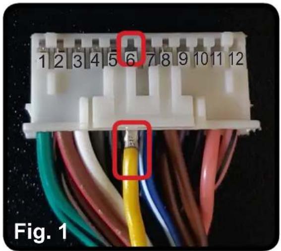
Visually inspect the AP4 harness at the JST connector that plugs into the AP4 interface. A loose pin may or may not be obviously visible. In the examples shown, a harness from the AP4-FD21 is being shown, but this applies to all of the AP4 interface harnesses.
- Check for pins in the open spaces of the AP4 interface connector. Each wire should have a corresponding visible pin in the open space above it. In Fig. 1, looking at the pin opening for the 6th pin position, it appears that there is no wire in that position. However, looking at the wire side of the connector for the 6th pin position (Fig. 2), the yellow wire is populated and it's pin should be visible. This indicates that the yellow wire is not fully seated into the connector.

natural_image
Close-up of a network cable connector with numbered pins (1–10) and a red square highlight on the middle section, labeled Fig. 2.Solution
If a wire is found that is not fully seated into the connector, reinsert the wire by pushing it fully into the connector until the pin can be seen in the opening on the side of the connector. The pin should lock into place. Notice that the pin is now visible in the 6th pin position. If necessary, remove some of the tesa tape on the harness to reduce stress on the pins.

AP4 Connector Diagrams
AP4-CH21
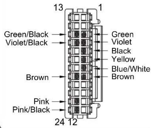
AP4-CH31

AP4-CH41
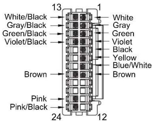
AP4-CH41(R2)

AP4-FD11
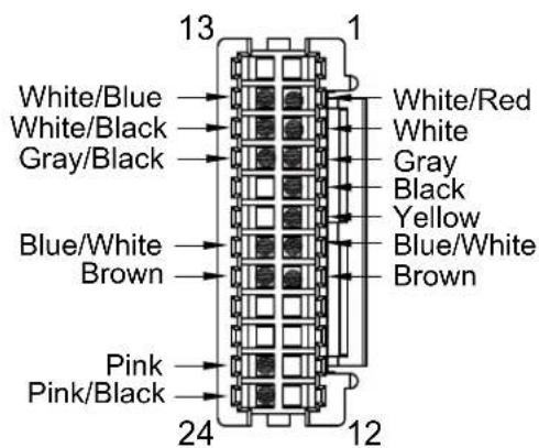
AP4-FD21

AP4 Connector Diagrams (cont.)
AP4-GM61
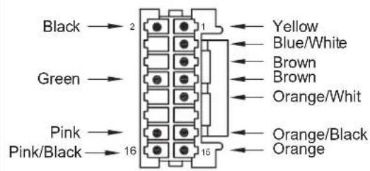
AP4-TY11

AP4-TY12

AP4-TY13




- Introduction and Features
- Important Notes
- Wiring Connection Chart
- Vehicle Connections Chart
- Vehicle Connections Chart (cont.)
- Module Layout
- Installation
- Voice / Nav Audio Connections
- Configuration A:
- Voice / Nav Audio Connections (cont.)
- Configuration B:
- Configuration C:
- - Config C, Version 3:
- - Config C, Version 3, Method 2 (cont.):
- Setup and Configuration
- Manually Setting the Radio's Beep Volume
- Setup and Configuration (cont.)
- Setting the radio's beep volume using the programming button
- Manually Setting the Minimum Volume
- Setting the minimum volume using the programming button
- AmpPRO App
- Use of the AmpPRO App allows you to do the following:
- AmpPRO App (cont.)
- Firmware Updates
- Restoring Factory Settings
- Troubleshooting
- Technical Bulletin
- Overview
- Inspect The Harness To Identify Pins That May Be Causing Issues
- Solution
- AP4 Connector Diagrams
- AP4 Connector Diagrams (cont.)
Brand : PAC
Model : AP4-TY11
Category : Receiver