Hydro Flex L19 - Lighting Adj - Free user manual and instructions
Find the device manual for free Hydro Flex L19 Adj in PDF.

| Product Type | LED Lighting Fixture |
| Model | Hydro Flex L19 |
| Brand | Adj |
| Light Source | LED |
| Power Consumption | 19W |
| Luminous Flux | 2000 lm |
| Color Temperature | 4000K (Neutral White) |
| Beam Angle | 120° |
| Input Voltage | 100-240V AC, 50/60Hz |
| Dimensions (LxWxH) | 600 x 100 x 70 mm |
| Weight | 1.2 kg |
| Housing Material | Aluminum |
| IP Rating | IP20 |
| Lifespan | 30000 hours |
| Dimmable | Yes (compatible with leading/trailing edge dimmer) |
| Mounting Type | Surface mount |
| Warranty | 2 years |
| Certifications | CE, RoHS |
| Operating Temperature | -20°C to +40°C |
| Package Includes | Fixture, mounting bracket, screws, instruction manual |
Frequently Asked Questions - Hydro Flex L19 Adj
User questions about Hydro Flex L19 Adj
0 question about this device. Answer the ones you know or ask your own.
Ask a new question about this device
Download the instructions for your Lighting in PDF format for free! Find your manual Hydro Flex L19 - Adj and take your electronic device back in hand. On this page are published all the documents necessary for the use of your device. Hydro Flex L19 by Adj.
USER MANUAL Hydro Flex L19 Adj
natural_image
Technical line drawing of a large radar or laser projector with hexagonal-patterned central component and base unit (no text or symbols)HYDRO FLEX LI9
User Manual
©2025 ADJ Products, LLC all rights reserved. Information, specifications, diagrams, images, and instructions herein are subject to change without notice. ADJ Products, LLC logo and identifying product names and numbers herein are trademarks of ADJ Products, LLC. Copyright protection claimed includes all forms and matters of copyrightable materials and information now allowed by statutory or judicial law or hereinafter granted. Product names used in this document may be trademarks or registered trademarks of their respective companies and are hereby acknowledged. All non-ADJ Products, LLC brands and product names are trademarks or registered trademarks of their respective companies.
ADJ Products, LLC and all affiliated companies hereby disclaim any and all liabilities for property, equipment, building, and electrical damages, injuries to any persons, and direct or indirect economic loss associated with the use or reliance of any information contained within this document, and/or as a result of the improper, unsafe, insufficient and negligent assembly, installation, rigging, and operation of this product.
ADJ PRODUCTS LLC World Headquarters
6122 S. Eastern Ave. | Los Angeles, CA 90040 USA
Tel: 800-322-6337 | www.adj.com lsupport@adj.com
ADJ Supply Europe B.V.
Junostraat 2 | 6468 EW Kerkrade | Netherlands
Tel: +31 45 546 85 00 | Fax: +31 45 546 85 99 | www.adj.eu | support@adj.eu
Europe Energy Saving Notice
Energy Saving Matters (EuP 2009/125/EC)
Saving electric energy is a key to help protecting the environment. Please turn off all electrical products when they are not in use. To avoid power consumption in idle mode, disconnect all electrical equipment from power when not in use. Thank you!
DOCUMENT VERSION

Due to additional product features and/or enhancements, an updated version of this document may be available online.
Please check www.adj.com for the latest revision/update of this manual before beginning installation and/or programming.
| Date | Document Version | Software Version | DMX Channels Notes |
| 01/20/2025 1.0 1.0.1 | 22 / 31 Std / 40 / 104 / 31 Std RGBW / 31 Std CMY / 34 | Initial Release | |
CONTENTS
General Information 4
Limited Warranty (USA Only) 5
Warranty Registration I Features 6
IP65 Rated 7
Safety Guidelines 8
Overview 9
Installation Guidelines 10
Remote Device Management (RDM) 14
Control Panel 15
System Menu 16
Fan Modes 20
DMX Setup 21
DMX Traits 23
Pixel Map 35
Color Wheels Table 36
Color Macros Chart 37
Dimmer Modes and Curves 39
Color Temperature 40
Cleaning and Maintenance 41
Torque Settings for Screws 42
IP Test Parameters 43
Error Codes 44
Specifications 45
Dimensional Drawings 46
FCC Statement 47
GENERAL INFORMATION
INTRODUCTION
Please read and understand the instructions in this manual carefully and thoroughly before attempting to operate this device. These instructions contain important safety and use information.
This product is intended for use by professionally trained personnel only, and is not suitable for private use.
FOR SOFTWARE UPDATES, CONTACT ADJ CUSTOMER SUPPORT.
Unpacking
Every device has been thoroughly tested and has been shipped in perfect operating condition. Carefully check the shipping carton for damage that may have occurred during shipping. If the carton is damaged, carefully inspect the device for damage, and be sure all accessories necessary to install and operate the device have arrived intact. In the event damage has been found or parts are missing, please contact our customer support team for further instructions. Please do not return this device to your dealer without first contacting customer support. Please do not discard the shipping carton in the trash. Please recycle whenever possible.
FOR SOFTWARE SUPPORT, CONTACT ADJ CUSTOMER SUPPORT.
CUSTOMER SUPPORT
Contact ADJ Service for any product related service and support needs. Also visit forums.adj.com with questions, comments or suggestions.
ADJ SERVICE USA - Monday - Friday 8:00am to 4:30pm PST 323-582-2650 | support@adj.com
ADJ SERVICE EUROPE - Monday - Friday 08:30 to 17:00 CET +31 45 546 85 60 | Fax: +31 45 546 85 96 | support@adj.eu
REPLACEMENT PARTS please visit parts.adj.com

IMPORTANT NOTICE!
THERE ARE NO USER SERVICEABLE PARTS INSIDE THIS UNIT. DO NOT ATTEMPT ANY REPAIRS YOURSELF; DOING SO WILL VOID YOUR MANUFACTURER'S WARRANTY. DAMAGES RESULTING FROM MODIFICATIONS TO THIS FIXTURE AND/OR THE DISREGARD OF SAFETY INSTRUCTIONS AND GUIDELINES IN THIS MANUAL VOID THE MANUFACTURER'S WARRANTY AND ARE NOT SUBJECT TO WARRANTY CLAIMS AND/OR REPAIRS.
LIMITED WARRANTY (USA ONLY)
A. ADJ Products, LLC hereby warrants, to the original purchaser, ADJ Products, LLC products to be free of manufacturing defects in material and workmanship for a prescribed period from the date of purchase (see specific warranty period on reverse). This warranty shall be valid only if the product is purchased within the United States of America, including possessions and territories. It is the owner's responsibility to establish the date and place of purchase by acceptable evidence, at the time service is sought.
B. For warranty service, you must obtain a Return Authorization number (RA#) before sending back the product-please contact ADJ Products, LLC Service Department at 800-322-6337. Send the product only to the ADJ Products, LLC factory. All shipping charges must be pre-paid. If the requested repairs or service (including parts replacement) are within the terms of this warranty, ADJ Products, LLC will pay return shipping charges only to a designated point within the United States. If the entire instrument is sent, it must be shipped in its original package. No accessories should be shipped with the product. If any accessories are shipped with the product, ADJ Products, LLC shall have no liability whatsoever for loss of or damage to any such accessories, or for the safe return thereof.
C. This warranty is void of the serial number has been altered or removed; if the product is modified in any manner which ADJ Products, LLC concludes, after inspection, affects the reliability of the product, if the product has been repaired or service by anyone other than ADJ Products, LLC factory unless prior written authorization was issued to purchaser by ADJ Products, LLC; if the product is damaged because not properly maintained as set forth in the instruction manual.
D. This is not a service contact, and this warranty does not include maintenance, cleaning or periodic check up. During the period specified above, ADJ Products, LLC will replace defective parts at its expense with new or refurbished parts, and will absorb all expenses for warrant service and repair labor by reason of defects in material or workmanship. The sole responsibility of ADJ Products, LLC under this warranty shall be limited to the repair of the product, or replacement thereof, including parts, at the sole discretion of ADJ Products, LLC. All products covered by this warranty were manufactured after August 15, 2012, and bear identifying marks to that effect.
E. ADJ Products, LLC reserves the right to make changes in design and/or improvements upon its products without any obligation to include these changes in any products theretofore manufactured.
F. No warranty, whether expressed or implied, is given or made with respect to any accessory supplied with products described above. Except to the extent prohibited by applicable law, all implied warranties made by ADJ Products, LLC in connection with this product, including warranties of merchantability or fitness, are limited in duration to the warranty period set forth above. And no warranties, whether expressed or implied, including warranties of merchantability or fitness, shall apply to this product after said period has expired. The consumer's and/or Dealer's sole remedy shall be such repair or replacement as is expressly provided above; and under no circumstances shall ADJ Products, LLC be liable for any loss or damage, direct or consequential, arising out of the use of, or inability to use, this product.
G. This warranty is the only written warranty applicable to ADJ Products, LLC Products and supersedes all prior warranties and written descriptions of warranty terms and conditions heretofore published.
LIMITED WARRANTY PERIODS
- Non L.E.D. Lighting Products = 1-year (365 days) Limited Warranty (Such as: Special Effect Lighting, Intelligent Lighting, UV lighting, Strobes, Fog Machines, Bubble Machines, Mirror Balls, Par Cans, Trussing, Lighting Stands etc. excluding LED and lamps)
- Laser Products = 1 Year (365 Days) Limited Warranty (excludes laser diodes which have 6 month limited warranty)
- L.E.D. Products = 2-year (730 days) Limited Warranty (excluding batteries which have a 180 day limited warranty)
Note: 2 Year Warranty only applies to purchases within the United States.
• StarTec Series = 1 Year Limited Warranty (excluding batteries which have a 180 day limited warranty) - ADJ DMX Controllers = 2 Year (730 Days) Limited Warranty
WARRANTY REGISTRATION
The Hydro Flex L19 carries a 2 year limited warranty. Please fill out the enclosed warranty card to validate your purchase. All returned service items, whether under warranty or not, must be freight pre-paid and accompanied by a return authorization (R.A.) number. The R.A. number must be clearly written on the outside of the return package. A brief description of the problem as well as the R.A. number must also be written down on a piece of paper included in the shipping carton. If the unit is under warranty, you must provide a copy of your proof of purchase invoice. You may obtain an R.A. number by contacting our customer support team on our customer support number. All packages returned to the service department not displaying an R.A. number on the outside of the package will be returned to the shipper.
FEATURES
- Moving Light Pixel Wash
• Individual Pixel Control
• Built-In Pixel Effect Programs
• Aria X2 Wireless Management System
• Electronic Strobe / Dimmer
• Pan/Tilt: 540/630 x 243 - Motorized Zoom
- Beam Angle: 5^ 38^
- Field Angle: 8^ 56^
• Color Calibrated Pixels so units match from batch to batch
• Virtual CMY DMX Control Modes
• Virtual Foreground and Background Color Wheel Control - Selectable LED Refresh Rates (900 Hz\~25K Hz)
- Selectable Dim Modes: Standard, Stage, TV, Arch., Theatre, Stage 2 and user settable Dim Speed (0.1S\~10S)
• 4 Dim Curves: Square, Linear, Inv. Square and S. Curve
• 0-100% smooth dimming - Fan Cooled
INCLUDED ITEMS:
- 2x Omega Bracket
- 1x Safety Cable
- 1x Power Cable
IP65 RATED
The International Protection (IP) rating system is commonly expressed as “IP” (Ingress Protection) followed by two numbers (i.e. IP65), where the numbers define the degree of protection. The first digit (Foreign Bodies Protection) indicates the extent of protection against particles entering the fixture, and the second digit (Water Protection) indicates the extent of protection against water entering the fixture. An IP65 rated lighting fixture is designed and tested to protect against the ingress of dust (6), and low-pressure water jets from any direction (5).
NOTE: THIS FIXTURE IS INTENDED FOR TEMPORARY OUTDOOR USE ONLY!
Maritime/Coastal Environment Installations: A coastal environment is seaside adjacent, and caustic to electronics through exposure to atomized salt-water and humidity, whereas maritime is anywhere within 5-miles of a coastal environment.

NOT suitable for maritime/coastal environment installations. Installing this fixture in a maritime/coastal environment may cause corrosion and/or excessive wear to the interior and/or exterior components of the fixture. Damages and/or performance issues resulting from installation in a maritime/coastal environment will void the manufactures warranty, and will NOT be subject to any warranty claims and/or repairs.
Maritime installations require additional preparation, and additional service intervals may be needed given the maritime use. In general, IP ratings presuppose freshwater conditions VS maritime conditions, which are typically more “caustic” to IP fixtures (both internally and externally). A duty-cycle may also be needed when units are not in use. During times of high humidity and colder temperatures, condensation may occur internally so the fixture may require a duty-cycle to bring it up to running temperature, allowing any accumulation of moisture to be expelled via the vent valve. Recommendations can change based on installation environmental circumstances. A waterproof dome or similar device is recommended for use in permanent outdoor installations. When using a dome, refer to manufacturer recommendations for duty-cycle.
NOTE: NOT ALL FEATURES LISTED ARE AVAILABLE ON ALL FIXTURES; THE FOLLOWING INSTRUCTIONS MAY NOT APPLY. CONTACT SUPPORT FOR ADDITIONAL DETAILS.
Exterior Maintenance: Inspect the exterior every 30-days. The unit must be powered off/disconnected. Inspect optics to determine if the lens is obstructed, then clean optics and chassis accordingly. Based on initial finding, schedule maintenance accordingly, keeping in mind that exterior maintenance will be required. Even if the luminaires are NOT in use, maintenance will still be needed given its location (exterior use). The use of a durable type of wax on the chassis is recommended since it will help prevent contaminant build up. Inspect both power and data lines for any signs of contaminants or corrosion. Periodically reapplying di-electric grease, especially in coastal environments. If any signs of corrosion/contaminants are present, clean thoroughly, and/or replace connectors, then reapply di-electric grease. Typically, this should be done annually, or any time an opportunity presents itself. As a preventive measure, annual replacement of both vent valves is recommended. The vent valve membrane can become contaminated and/or clogged causing improper venting of humidity within the luminaire. Inspect all mounting hardware as a precaution.
Interior Maintenance: Inspect the interior every 30-days. The unit must be powered off/disconnected.
- Inspect zoom/focus mechanism, clean optics, lubricate linear bearings (Krytox oil) as needed, inspect belts for wear
- Inspect all rotating effect wheels, manually rotate them, note any resistance
- Inspect all remaining rotating belts for any wear
- Inspect all fans, clean as needed, check rotation, check connections
- Inspect CMY module, manually move flags and check for signs of resistance, and if needed, clean guide rods first, then reapply a thin layer of grease (moly lube)
- Clean interior with low-volume compressed air, then clean optics prior to reassembly of head covers
Although the base has limited moving parts, the pan belt should also be inspected for wear. Remember to always perform an IP test anytime a cover is removed.
There is no specific time frame regarding the routine replacement of parts such as belts/stepper motors, PCBs, or LEDs. These items should only be replaced on an as needed bases, except for cooling fans, which should be replaced once the luminaries reach 10,000-hours. This is a prophylactic measure intended to keep the unit running as cool as possible, insuring proper function of all internal components. A complete service breakdown is available, please contact service@adj.com for any needed parts or manuals.
SAFETY GUIDELINES
THIS FIXTURE IS COMPOSED OF SOPHISTICATED ELECTRONIC COMPONENTS. TO GUARANTEE SMOOTH OPERATION, IT IS IMPORTANT TO FOLLOW ALL INSTRUCTIONS AND GUIDELINES IN THIS MANUAL. ADJ PRODUCTS, LLC IS NOT RESPONSIBLE FOR INJURY AND/OR DAMAGES RESULTING FROM THE MISUSE OF THIS FIXTURE DUE TO THE DISREGARD OF THE INFORMATION PRINTED IN THIS MANUAL. ONLY QUALIFIED AND/OR CERTIFIED PERSONNEL SHOULD PERFORM INSTALLATION OF THIS FIXTURE AND ONLY THE ORIGINAL RIGGING PARTS INCLUDED WITH THIS FIXTURE SHOULD BE USED FOR INSTALLATION. ANY MODIFICATIONS TO THE FIXTURE AND/OR THE INCLUDED MOUNTING HARDWARE WILL VOID THE ORIGINAL MANUFACTURER'S WARRANTY AND INCREASE THE RISK OF DAMAGE AND/OR PERSONAL INJURY. ONLY CERTIFIED PERSONNEL SHOULD PERFORM INSTALLATION OF THIS FIXTURE.
• PROTECTION CLASS 1 - FIXTURE MUST BE PROPERLY GROUNDED.
- THERE ARE NO USER SERVICEABLE PARTS INSIDE THIS UNIT.
- DO NOT ATTEMPT ANY REPAIRS YOURSELF; DOING SO WILL VOID YOUR MANUFACTURER'S WARRANTY. DAMAGES RESULTING FROM MODIFICATIONS TO THIS FIXTURE AND/OR THE DISREGARD OF SAFETY INSTRUCTIONS AND GUIDELINES IN THIS MANUAL VOID THE MANUFACTURER'S WARRANTY AND ARE NOT SUBJECT TO ANY WARRANTY CLAIMS AND/OR REPAIRS.
• DO NOT PLUG FIXTURE INTO A DIMMER PACK!
- NEVER OPEN THIS FIXTURE WHILE IN USE!
- UNPLUG POWER BEFORE SERVICING FIXTURE!
- NEVER TOUCH FIXTURE DURING OPERATION, AS IT MAY BE HOT!
- KEEP FLAMMABLE MATERIALS AWAY FROM FIXTURE!
- NEVER LOOK DIRECTLY INTO THE LIGHT SOURCE!
• RETINA INJURY RISK - MAY INDUCE BLINDNESS!
• SENSITIVE PERSONS MAY SUFFER AN EPILEPTIC SHOCK!
- MINIMUM DISTANCE TO OBJECTS/SURFACES AND FLAMMABLE SURFACES IS 21 INCHES (520 mm).
- The fixture should be installed in such a way that the light output will not be aimed directly at viewers or personnel at a distance of 8 ft (2.4m) or less.
- DO NOT TOUCH the fixture housing during operation. Turn OFF the power and allow approximately 60 minutes for the fixture to cool down before serving.
- DO NOT shake fixture, and avoid brute force when installing and/or operating fixture.
- DO NOT operate fixture if the power cord is frayed, crimped, damaged and/or if any of the power cord connectors are damaged and do not insert into the fixture securely with ease. NEVER force a power cord connector into the fixture. If the power cord or any of its connectors are damaged, replace it immediately with a new one of the same power rating.
- DO NOT block any air ventilation slots. All fan and air inlets must remain clean and never blocked. Allow approx. 6" (15cm) between fixture and other devices or a wall for proper cooling.
- When installing fixture in a suspended environment, always use mounting hardware that is no less than M10 x 25 mm, and always install fixture with an appropriately rated safety cable.
- Always disconnect fixture from main power source before performing any type of service and/or cleaning procedure.
- Only handle the power cord by the plug end. Never pull out the plug by tugging the wire portion of the cord.
- During the initial operation of this fixture, a light smoke or smell may emit from the interior of the fixture. This is a normal process and is caused by excess paint in the interior of the casing burning off from the heat associated with the lamp and will decrease gradually over time.
- Consistent operational breaks will ensure fixture will function properly for many years.
- Only use original packaging and materials to transport the fixture for service.
- The light source used in this fixture should only be replaced by the manufacturer or qualified service personnel.
- This fixture is intended for professional use only.
OVERVIEW

text_image
Mode Button Up Button Enter Button Tilt Lock Pan Lock Display Screen MODE UP LEFT ENTER RIGHT DOWN Left Button Down Button Right Button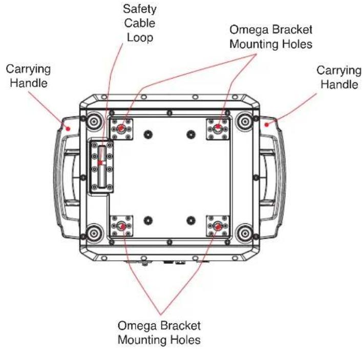
text_image
Carrying Handle Safety Cable Loop Omega Bracket Mounting Holes Carrying Handle Omega Bracket Mounting Holes
text_image
Power In Fuse T15A / 250V Air Valve Net Out Net In DMX In DMX OutINSTALLATION GUIDELINES

FLAMMABLE MATERIAL WARNING
Keep fixture minimum 21 inches (520mm) away from flammable materials and/or pyrotechnics.

ELECTRICAL CONNECTIONS
A qualified electrician should be used for all electrical connections and/or installations.

MINIMUM DISTANCE TO OBJECTS/SURFACES OR FLAMMABLE MATERIALS IS 21 INCHES (520 mm).
DO NOT INSTALL THE FIXTURE IF YOU ARE NOT QUALIFIED TO DO SO!
- Fixture MUST be installed following all local, national, and country commercial electrical and construction codes and regulations.
- Before rigging/mounting a single fixture or multiple fixtures to any metal truss/structure or placing the fixture(s) on any surface, a professional equipment installer MUST be consulted to determine if the metal truss/structure or surface is properly certified to safely hold the combined weight of the fixture(s), clamps, cables, and accessories.
- Ambient operating temperature range is -4^ to 113^ (-20°C to 45°C). Do not use fixture when ambient temperature falls outside of this range.
- Fixture(s) should be installed outside walking paths, seating areas, or areas where unauthorized personnel might reach the fixture by hand.
- NEVER stand directly below the fixture(s) when rigging, removingm, or servicing.
• Overhead fixture installation must always be secured with a secondary safety attachment, such as an appropriately rated safety cable. - Allow approximately 60 minutes for the fixture to cool down before servicing.
RIGGING
Overhead rigging requires extensive experience, including calculating working load limits, knowledge of installation material being used, and periodic safety inspection of all installation material and the fixture, among other skills. If you lack these qualifications, do not attempt the installation yourself. Improper installation can result in bodily injury.
INSTALLATION GUIDELINES
CLAMP INSTALLATION
To suspend this fixture from a truss or other elevated installation, begin by attaching appropriately rated mounting clamps to each of the included Omega brackets. Align the hole on the mounting clamp with the hole on the Omega bracket, then insert an appropriately rated bolt through both holes and secure in place with a matching washer and nut, as shown in the image below. Use the twist-lock fasteners on the Omega bracket to secure the mounting clamp and Omega bracket assembly to the mounting points on the underside of the fixture's base. Please note that two (2) mounting clamps and two (2) Omega brackets are required install the fixture safely and securely.
Secure a separate SAFETY CABLE of the appropriate weight rating to the safety cable loop located on the underside of the fixture's base. Never use the carrying handles or location other than the designated safety cable loop for the attachment of the safety cable.

text_image
SAFETY CABLE ATTACHED TO CABLE LOOPSAFETY CABLE:

ALWAYS ATTACH A SAFETY CABLE WHENEVER INSTALLING THIS FIXTURE IN A SUSPENDED ENVIRONMENT TO ENSURE THAT THE FIXTURE WILL NOT FALL IF THE CLAMPS FAIL.
INSTALLATION GUIDELINES
RIGGING
Overhead rigging requires extensive experience, including among others, calculating working load limits, installation material being used, and periodic safety inspection of all installation material and the fixture. If you lack these qualifications, do not attempt the installation yourself. Improper installation can result in bodily injury.
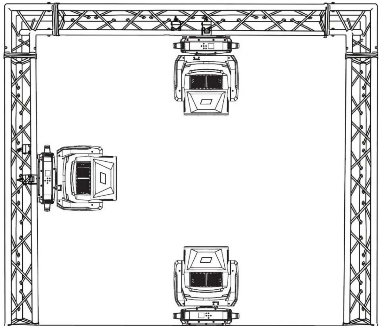
This fixture is designed to be mounted vertically (hanging or upright), or horizontally (perpendicular to vertical axis) only.
natural_image
Technical line drawing of three identical mechanical components mounted on a truss structure (no text or symbols)
FALLING FIXTURES CAN CAUSE SEVERE INJURY OR SERIOUS EQUIPMENT DAMAGE! FOR THIS REASON, FIXTURES SHOULD BE INSTALLED AND INSPECTED ONLY BY QUALIFIED PERSONNEL. DO NOT INSTALL THE UNIT IF YOU LACK THE QUALIFICATIONS TO DO SO, OR IF YOU HAVE DOUBTS ABOUT THE SAFETY AND SECURITY OF THE INSTALLATION SETUP OR LOCATION!

ALWAYS ATTACH A SAFETY CABLE WHENEVER INSTALLING THIS FIXTURE IN A SUSPENDED ENVIRONMENT TO ENSURE THE FIXTURE WILL NOT FALL IF THE CLAMP FAILS.
INSTALLATION GUIDELINES
POTENTIAL INTERNAL FIXTURE DAMAGE FROM EXTERNAL SOURCES OF LIGHT BEAMS
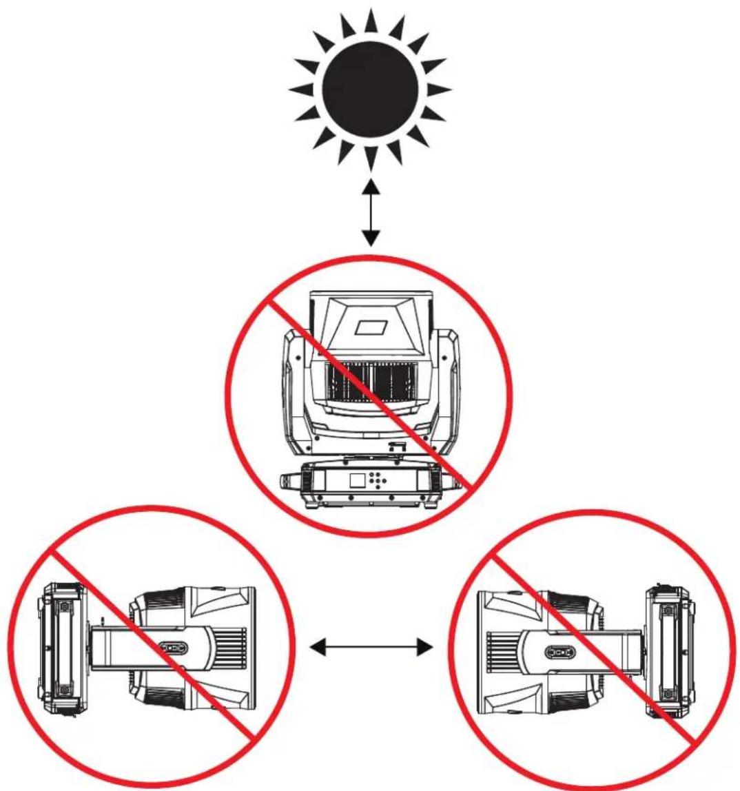
External sources of light beams from direct sunlight, lighting and moving head fixtures, and lasers, which are focused directly towards the exterior housing and/or penetrate the front lens opening of Elation lighting fixtures, can cause severe internal damage including burning of optics, dichroic color filters, glass and metal gobos, prisms, animation wheels, frost filters, iris, shutters, motors, belts, wiring, discharge lamps, and LEDs.
This issue is not specific only to ADJ lighting fixtures, but rather it is a common issue with lighting fixtures from all manufacturers. Although there is no true way to fully prevent this issue from happening, the guidelines below can reduce the risk of potential damage. Contact ADJ Service for more details.
DO NOT EXPOSE THE FIXTURE AND/OR FRONT LENS OPENING TO LIGHT BEAMS FROM DIRECT SUNLIGHT, OTHER LIGHTING OR MOVING HEAD FIXTURES, AND LASERS DURING UNPACKING, INSTALLATION, USE, AND EXTENDED IDLE TIMES OUTDOORS. DO NOT FOCUS A LIGHT BEAM FROM ONE LIGHTING FIXTURE DIRECTLY TOWARDS ANOTHER.
flowchart
graph TD
    A["太阳"] --> B["设备1"]
    A --> C["设备2"]
    A --> D["设备3"]
    B -->|无辐射| E["设备1"]
    C -->|无辐射| F["设备2"]
    D -->|无辐射| G["设备3"]
REMOTE DEVICE MANAGEMENT (RDM)
NOTE: for RDM to work properly, RDM enabled equipment must be used throughout the entire system, including DMX data splitters and wireless systems.
Remote Device Management (RDM) is a protocol that sits on top of the DMX512 data standard for lighting, allowing the DMX systems of the fixtures to be modified and monitored remotely. This protocol is ideal for instances in which a unit is installed in a location that is not easily accessible.
With RDM, the DMX512 system becomes bi-directional, allowing a compatible RDM enabled controller to send out a signal to devices on the wire, as well as allowing the fixture to respond (known as a GET command). The controller can then use its SET command to modify settings that would typically have to be changed or viewed directly via the unit's display screen, including the DMX Address, DMX Channel Mode, and Temperature Sensors.
FIXTURE RDM INFORMATION:
| RDM Code Device ID | Device Model ID | Personality ID |
| 0x0046 46 0000 46 | Basic 22 (1), Standard 31 (2), Extended 40 (3),Extended 104 (4), Standard RGBW 31 (5),Standard CMY 31 (6), Extended CMY 34 (7) |
Please be aware that not all RDM devices support all RDM features, and therefore it is important to check beforehand to ensure that the equipment that you are considering includes all of the features that you require.
The following parameters are accessible in RDM on this device:
| Code Parameter ID | Code Parameter ID |
| [0x0011] Proxied Device Count | [0x0601] Tilt Invert |
| [0x0200] Sensor Definition | [0x0602] Pan Tilt Swap |
| [0x0201] Sensor Value | [0x0500] Display Invert |
| [0x0080] Device Model Description | [0x0501] Display Level |
| [0x0081] Manufacturer Label | [0x0603] Realtime Clock |
| [0x0082] Device Label | [0x1010] Power State |
| [0x00E0] DMX Personality | [0x1031] Preset Playback |
| [0x00E1] DMX Personality Description | [0x0122] Default Slot Value |
| [0x0400] Device Hours | [0x00B0] Language |
| [0x0015] Comms Status | [0x00A0] Language Capabilities |
| [0x0031] Status ID Description | [0x00C2] Boot Software Version Label |
| [0x0032] Clear Status ID | [0x00C1] Boot Software Version ID |
| [0x0405] Device Power Cycles | [0x0070] Product Detail ID List |
| [0x0600] Pan Invert | [0x0030] Status Messages |
CONTROL PANEL
The fixture includes an easy to navigate system menu control panel display where all necessary settings and adjustments are made.
- MODE: Leave current menu and return to previous menu level.
• UP: Scroll up in currently displayed menu.
• LEFT: Scroll left in currently displayed menu.
• RIGHT: Scroll right in currently displayed menu. - DOWN: Scroll down in currently displayed menu.
- ENTER: Select an option or confirm a selection.

text_image
HYDRO MODE UP LEFT ENTER RIGHT DOWN HYDRO FLEX LI9SCREEN SAVER
This fixture includes a screen saver function, which turns off the display after a certain period of inactivity, but the screen can be turned back on immediately simply by touching any control key. The period of inactivity is set to 5 minutes by default, but can be set to a different length of time or even turned off entirely by using the system menu to navigate to Personality > Display > Screen Saver Delay.
KEY LOCK
This fixture also includes a key lock function, which automatically shuts off the display screen and locks the control keys after a certain period of inactivity. This period of inactivity corresponds to the value for the Screen Saver Delay. The key lock feature is OFF by default, but this status can be changed by using the system menu to navigate to Personality > Display > Key Lock. The selectable options are as described below:
• OFF: Control keys never lock, even if the display screen goes to sleep.
- ON: Control keys lock after a certain period of inactivity, and can be unlocked by pressing and holding the MODE button for 3 seconds.
- ON1: Control keys lock after a certain period of inactivity, and can be unlocked by pressing UP, DOWN, UP, DOWN, ENTER in sequence.
SYSTEM MENU
| MAIN MENU OF TIONS / VALUES (Default Settings in BOLD) DESCRIPTION | |||||
| DMX Settings | DMX Address 001 - XXX | Set DMX starting address | |||
| DMX Channel Mode | Basic 22 | Select DMX channel mode | |||
| Standard 31 | |||||
| Extended 40 | |||||
| Extended 104 | |||||
| Standard RGBW 31 | |||||
| Standard CMY 31 | |||||
| Standard CMY 34 | |||||
| User Mode | |||||
| Hold Last | Fixture holds last received settings if DMX signal is lost | ||||
| Blackout | Fixture takes all channels to zero if DMX signal is lost | ||||
| Manual | Fixture defaults to manual settings if DMX signal is lost | ||||
| Internal Programs | Fixture defaults to pre-selected internal program if DMX signal is lost | ||||
| Personality | Prim / Sec Mode Primary / Secondary | Set unit as a primary or secondary unit | |||
| Select Signal | DMX or Aria X2 | Configure input and output signal | |||
| Aria X2 and DMX Out | |||||
| Aria Settings | Frequency | 2.4GHz | Select Aria frequency | ||
| Sub Gig US | |||||
| Sub Gig EU | |||||
| 2.4 GHz Ch 00 - 15 | Select 2.4 GHz channel | ||||
| Sub Gig Ch 00 - 09 | Select sub gig channel | ||||
| Mesh On / Off | Enables or disables DMX mesh, which allows data to be shared between units in a decentralized manner | ||||
| RDM On / Off | Enables or disables remote device management | ||||
| Bluetooth On / Off | Enables or disables Bluetooth | ||||
| Network | Input On / Off | Enable or disable network input ports | |||
| Protocol ArtNet / sACN | Select network port protocol | ||||
| KlingNet On / Off | Enable or disable KlingNet | ||||
| Address | Set Universe 00 | 0 - 32767 | Set ArtNet universe | ||
| Ethernet IP | 002.000.000.001 | Set Ethernet IP address | |||
| Ether Mask IP 2 | 55.000.000.000 | Set Ethernet mask IP address | |||
SYSTEM MENU
| MAIN MENU OPTIONS / VALUES (Default Settings in BOLD) DESCRIPTION | ||||
| Personality(continued) | Status Settings | Pan Degree 630 / 540 | Select pan degree | |
| Pan Invert On / Off | Enable or disable pan inversion | |||
| Tilt Invert On / Off | Enable or disable tilt inversion | |||
| P/T Feedback On / Off | Enable or disable pan/tilt feedback | |||
| P/T Speed Speed 1 / Hibernation | Speed 2 | Set pan/tilt speed | ||
| Off, 1min - 99min, default = 15min | Set time after which unit goes into hibernation | |||
| Fan Settings | Head Fan | Auto | Select head fan setting | |
| High | ||||
| Low | ||||
| Base Fan | Auto | Select base fan setting | ||
| High | ||||
| Low | ||||
| Zoom Speed Standard / Fast | Set zoom speed | |||
| Zoom Mode | Mode 1 | Zoom range goes from full minimum to full maximum | ||
| Mode 2 | Zoom range limited when zoomed in so as not to overshoot focal point | |||
| LED Power Mode | LP Mode 1 | Standard maximum LED power output | ||
| LP Mode 2 | Regulated LED output with 8500K target CCT | |||
| Dim Mode | Standard | Select dim mode | ||
| Stage | ||||
| TV | ||||
| Architectural | ||||
| Theatre | ||||
| Stage 2 | ||||
| Dim Speed 0.1s - 10s | Set dim speed | |||
| LED Refresh Rate | 900 - 1500Hz, 2500Hz, 4000Hz, 5000Hz, 6000Hz, 10KHz, 15KHz, 20KHz, 25KHz; Default = 1200Hz | Set LED refresh rate | ||
| Dim Curve | Linear | Select dim curve | ||
| Square | ||||
| Inv Squa | ||||
| S Curve | ||||
| Pixel Map Mode | Mode 1 | Extended 40Ch Map | ||
| Mode 2 | Extended 104Ch Map | |||
| Reset Motors | Reset All Motors Yes / No | Reset selected motors | ||
| Pan / Tilt Reset Yes / No | ||||
| Effect Reset Yes / No | ||||
SYSTEM MENU
| MAIN MENU OPTIONS / VALUES (Default Settings in BOLD) DESCRIPTION | |||||
| Personality(continued) | Display | Intensity 1 - 10 | Set display screen intensity level | ||
| Display Invert Yes / No | Enable or disable display screen inversion | ||||
| Screen Saver Delay | Off - 10min, Default = 5min | Display screen switches off after selected period of inactivity | |||
| Key Lock | Off | Control keys do not lock | |||
| On | Control keys lock after selected period of inactivity; to unlock press and hold MODE for 3 sec | ||||
| On1 | Control keys lock after selected period of inactivity; to unlock press UP, DOWN, UP, DOWN, ENTER | ||||
| Set User Mode | Pan 1 | Custom assignment of DMX channel numbers; default values are as shown in Extended (104-ch) mode | |||
| Pan Fine 2 | |||||
| Tilt 3 | |||||
| Tilt Fine 4 | |||||
| Red 1 5 | |||||
| Green 1 6 | |||||
| Blue 1 7 | |||||
| Lime 1 8 | |||||
| ... ... | |||||
| Red 19 77 | |||||
| Green 19 | 78 | ||||
| Blue 19 | 79 | ||||
| Lime 19 | 80 | ||||
| ... ... | |||||
| P/T Speed | 103 | ||||
| Special | 104 | ||||
| Service Passcode = 050 | Effect Adjustment, White Balance | Pan 000 - 255 | Adjust effects and white color balance | ||
| Tilt 000 - 255 | |||||
| Red 000 - 255 | |||||
| Green 000 - 255 | |||||
| Blue 000 - 255 | |||||
| White 000 - 255 | |||||
| ... | |||||
| Color Calibration | Enable / Disable | Enable or disable color calibration | |||
| Factory Restore | Off / On Passcode = 011 | Restore fixture to factory default settings | |||
SYSTEM MENU
| MAIN MENU OPTIONS / VALUES (Default Settings in BOLD) DESCRIPTION | |||||
| Manual Control | Pan 000 - 255 | Manually set each fixture parameter | |||
| Pan Fine 000 - 255 | |||||
| Tilt 000 - 255 | |||||
| Tilt Fine 000 - 255 | |||||
| ... ... | |||||
| Internal Programs | Program 1 | Speed 000 - 255 | Select internal program to run, and set program speed and fade | ||
| Fade 000 - 255 | |||||
| Program 2 | Speed 000 - 255 | ||||
| Fade 000 - 255 | |||||
| ... ... ... | |||||
| Program 20 | Speed 000 - 255 | ||||
| Fade 000 - 255 | |||||
| Information | Fixture Life Time | Power On Time xxxxx Hours | Total lifetime hours that fixture has been powered on | ||
| P-On Time-R xxxxxx Hours | Hours that fixture has been powered on since last reset | ||||
| P-On Time-Reset Passcode = 050 | Reset P-On Time-R | ||||
| Total LED Time | LED On Time | xxxxx Hours | Total lifetime hours that LED has been powered on | ||
| LED On Time-R | xxxxx Hours | Hours that LED has been powered on since last reset | |||
| LED Hours Reset | Passcode = 050 | Reset LED On Time-R | |||
| Fixture Temps | LEDs | Current | xxx F / xxx C | Current LED temp | |
| Max Resettable | xxx F / xxx C | Max recorded LED temp since last reset | |||
| Base Temp | Current | xxx F / xxx C | Current base temp | ||
| Max Resettable | xxx F / xxx C | Max recorded base temp since last reset | |||
| Reset LED Temp | Yes / No | Passcode = 050 | Reset LED Max Resettable temp | ||
| Reset Base Temp | Yes / No | Passcode = 050 | Reset Base Max Resettable temp | ||
| Humidity | xxx% | Current humidity reading | |||
| Fan Info | LED Fan | xxxx RPM LED | Current LED fan speed | ||
| Base Fan xxxx RPM | Current base fan speed | ||||
| DMX Values | Pan | Display current value of each DMX parameter | |||
| Pan Fine | |||||
| ... | |||||
| Error Logs | Error 1, Error 2, ... | List errors one by one | |||
| Reset Error Log | Yes / No | Passcode = 050 | Clear error logs | ||
| Software Version | U: xxx | Display current software version | |||
| Aria ID | xx:xx:xx:xx:xx:xx | Display current Aria ID | |||
FAN MODES
The Hydro Flex L19 is a high-performance fixture suited for multiple applications. For noise critical environments such as Theater, Opera or Orchestra Halls, it offers various fan operation modes which remove any distraction for the audience and performers. Fan Modes can be changed remotely via the DMX control channel, allowing the fixture to offer high output or whisper silent operation at a moment's notice. All Fan Modes smoothly transition over a brief time, preventing unwanted attraction to the fixture.
Auto (Default)—Fans only run at the speeds needed to keep the LED engine within a safe temperature range and ensures optimal performance of the fixture. If possible, they will turn-off, for example, when the fixture is dimmed to a low intensity. Fans sense the ambient and fixture temperature, and will always try to keep noise levels to a minimum. The fixture output will only reduce when the LED engine cannot be cooled down to its safe operating range due to high ambient temperature.
NOTE: Recommended for daily operation.
High—Fan speeds are increased throughout for the most efficient cooling of the fixture. This mode will increase wear on the fans and should only be utilized in exceptional circumstances. Fans will always run, even if the fixture is dimmed down. Fixture output is kept at 100% unless the LED engine temperature reaches an unsafe temperature at which point the fixture will reduce power carefully to ensure continued safe operation. This mode is only required in very high ambient temperatures when automatic fan speed adjustments are not desired.
Low— For very critical noise environments. 75-80% max output, fans run at low speed. The fixture output will be reduced, yet due to the extremely high luminous flux, the fixture still offers outstanding performance. All parameters of the fixture operate more quietly with reduced fan speeds.
DMX SETUP
DMX-512: DMX is short for Digital Multiplex. This is a universal protocol used as a form of communication between intelligent fixtures and controllers. A DMX controller sends DMX data instructions from the controller to the fixture. DMX data is sent as serial data that travels from fixture to fixture via the DATA "IN" and DATA "OUT" XLR terminals located on all DMX fixtures (most controllers only have a DATA "OUT" terminal).
DMX Linking: DMX is a language allowing all makes and models of different manufacturers to be linked together and operate from a single controller, as long as all fixtures and the controller are DMX compliant. To ensure proper DMX data transmission, try to use the shortest cable path possible when using several DMX fixtures. The order in which fixtures are connected in a DMX line does not influence the DMX addressing. For example, a fixture assigned a DMX address of 1 may be placed anywhere in a DMX line: at the beginning, at the end, or anywhere in the middle. When a fixture is assigned a DMX address of 1, the DMX controller knows to send DATA assigned to address 1 to that unit, no matter where it is located in the DMX chain.
Data Cable (DMX Cable) Requirements (For DMX Operation): This fixture can be controlled via DMX-512 protocol, and features multiple DMX channel modes. Your unit and your DMX controller require a 5-pin XLR connector for data input and data output. If you are making your own cables, be sure to use standard 110-120 Ohm shielded cable (This cable may be purchased at almost all pro lighting stores). Your cables should be made with a male XLR connector at one end and a female XLR connector on the other. Also remember that DMX cable must be daisy chained and cannot be split.
Special Note: Line Termination. When longer runs of cable are used, you may need to use a terminator on the last unit to avoid erratic behavior. A terminator is a 110-120 ohm 1/4 watt resistor which is connected between pins 2 and 3 of a male XLR connector (DATA + and DATA -). This unit is inserted in the female XLR connector of the last unit in your daisy chain to terminate the line. Using a cable terminator (ADJ part number Z-DMX/T) will decrease the chances of erratic behavior.

A DMX512 terminator reduces signal errors, avoiding most signal reflection interference. Connect PIN 2 (DMX-) and PIN 3 (DMX+) of the last fixture in series with a 120 Ohm, 1/4 W Resistor to terminate the DMX512.
DMX SETUP
DMX ADDRESSING
All fixtures should be given a DMX starting address when operating with a DMX controller, in order to ensure that the correct fixture responds to the correct control signal. This digital starting address is the channel number from which the fixture starts to “listen” to the digital control signal sent out from the DMX controller. The assignment of this starting DMX address is achieved by setting the correct DMX address on the digital control display on the fixture.
You can set the same starting address for all fixtures or a group of fixtures, or set different addresses for each individual fixture. Setting all fixtures to the same DMX address will cause all fixtures to react in the same way. In this case, please note that changing the settings of one channel will affect all the fixtures simultaneously.
If you set each fixture to a different DMX address, each unit will "listen" starting at the channel number you have set, based on the quantity of DMX channels of each fixture. That means changing the settings of one channel will only affect the selected fixture.
As an example, when operating this device in 22 channel mode, you should set the starting DMX address of the first unit to 1, the second unit to 23 (1 + 22), the third unit to 45 (1 + 22 + 22), and so on. (See the chart below for more details.)
| Channel Mode Unit 1 Address Unit 2 | Address Unit 3 Address Unit 4 Address | ||
| 22 Channels 1 23 45 67 | |||
| 31 Channels(Standard) | 1 32 63 94 | ||
| 40 Channels 1 41 81 121 | |||
| 104 Channels 1 105 209 313 | |||
| 31 Channels(Standard RGBW) | 1 32 63 94 | ||
| 31 Channels(Standard CMY) | 1 32 63 94 | ||
| 34 Channels 1 35 69 103 | |||
DMX TRAITS
| CHANNEL | DMX VALUES | FUNCTION | ||||||
| 22 CH | 31 CH STD | 40 CH | 104 CH | 31 CH STD RGBW | 31 CH STD CMY | 34 CH | ||
| 1 1 1 | 1 1 1 1 | Pan Movement, 8-bit | ||||||
| 000 - 255 | 540 / 630 Degrees | |||||||
| 2 2 2 | 2 2 2 | Pan Fine Movement, 16-bit | ||||||
| 000 - 255 | Pan Fine Movement | |||||||
| 2 3 3 | 3 3 3 3 | Tilt Movement, 8-bit | ||||||
| 000 - 255 | 270 Degrees | |||||||
| 4 4 4 | 4 4 4 | Tilt Fine Movement, 16-bit | ||||||
| 000 - 255 | Tilt Fine Movement | |||||||
| 3 5 5 | Red | |||||||
| 000 - 255 | 0% - 100% | |||||||
| 4 6 6 | Green | |||||||
| 000 - 255 | 0% - 100% | |||||||
| 5 7 7 | Blue | |||||||
| 000 - 255 | 0% - 100% | |||||||
| 6 8 8 | Lime | |||||||
| 000 - 255 | 0% - 100% | |||||||
| 5 | 5 | Red 1 | ||||||
| 000 - 255 | 0% - 100% | |||||||
| 6 | 6 | Green 1 | ||||||
| 000 - 255 | 0% - 100% | |||||||
| 7 | 7 | Blue 1 | ||||||
| 000 - 255 | 0% - 100% | |||||||
| 8 | 8 | Lime 1 | ||||||
| 000 - 255 | 0% - 100% | |||||||
| 9 | 9 | Red 2 | ||||||
| 000 - 255 | 0% - 100% | |||||||
| 10 10 | Green 2 | |||||||
| 000 - 255 | 0% - 100% | |||||||
| 11 11 | Blue 2 | |||||||
| 000 - 255 | 0% - 100% | |||||||
| 12 12 | Lime 2 | |||||||
| 000 - 255 | 0% - 100% | |||||||
| 13 13 | Red 3 | |||||||
| 000 - 255 | 0% - 100% | |||||||
| 14 14 | Green 3 | |||||||
| 000 - 255 | 0% - 100% | |||||||
| 15 15 | Blue 3 | |||||||
| 000 - 255 | 0% - 100% | |||||||
| 16 16 | Lime 3 | |||||||
| 000 - 255 | 0% - 100% | |||||||
DMX TRAITS
| CHANNEL | DMX VALUES | FUNCTION | ||||||
| 22 CH | 31 CH STD | 40 CH | 104 CH | 31 CH STD RGBW | 31 CH STD CMY | 34 CH | ||
| 17 | Red 4 | |||||||
| 000 - 255 0% - 100% | ||||||||
| 18 | Green 4 | |||||||
| 000 - 255 0% - 100% | ||||||||
| 19 | Blue 4 | |||||||
| 000 - 255 0% - 100% | ||||||||
| 20 | Lime 4 | |||||||
| 000 - 255 0% - 100% | ||||||||
| 21 | Red 5 | |||||||
| 000 - 255 0% - 100% | ||||||||
| 22 | Green 5 | |||||||
| 000 - 255 0% - 100% | ||||||||
| 23 | Blue 5 | |||||||
| 000 - 255 0% - 100% | ||||||||
| 24 | Lime 5 | |||||||
| 000 - 255 0% - 100% | ||||||||
| 25 | Red 6 | |||||||
| 000 - 255 0% - 100% | ||||||||
| 26 | Green 6 | |||||||
| 000 - 255 0% - 100% | ||||||||
| 27 | Blue 6 | |||||||
| 000 - 255 0% - 100% | ||||||||
| 28 | Lime 6 | |||||||
| 000 - 255 0% - 100% | ||||||||
| 29 | Red 7 | |||||||
| 000 - 255 0% - 100% | ||||||||
| 30 | Green 7 | |||||||
| 000 - 255 0% - 100% | ||||||||
| 31 | Blue 7 | |||||||
| 000 - 255 0% - 100% | ||||||||
| 32 | Lime 7 | |||||||
| 000 - 255 0% - 100% | ||||||||
| 33 | Red 8 | |||||||
| 000 - 255 0% - 100% | ||||||||
| 34 | Green 8 | |||||||
| 000 - 255 0% - 100% | ||||||||
| 35 | Blue 8 | |||||||
| 000 - 255 0% - 100% | ||||||||
| 36 | Lime 8 | |||||||
| 000 - 255 0% - 100% | ||||||||
DMX TRAITS
| CHANNEL | ||||||||
| 22 CH | 31 CH STD | 40 CH | 104 CH | 31 CH STD RGBW | 31 CH STD CMY | 34 CH | DMX VALUES | FUNCTION |
| 37 | Red 9 | |||||||
| 000 - 255 0% - 100% | ||||||||
| 38 | Green 9 | |||||||
| 000 - 255 0% - 100% | ||||||||
| 39 | Blue 9 | |||||||
| 000 - 255 0% - 100% | ||||||||
| 40 | Lime 9 | |||||||
| 000 - 255 0% - 100% | ||||||||
| 41 | Red 10 | |||||||
| 000 - 255 0% - 100% | ||||||||
| 42 | Green 10 | |||||||
| 000 - 255 0% - 100% | ||||||||
| 43 | Blue 10 | |||||||
| 000 - 255 0% - 100% | ||||||||
| 44 | Lime 10 | |||||||
| 000 - 255 0% - 100% | ||||||||
| 45 | Red 11 | |||||||
| 000 - 255 0% - 100% | ||||||||
| 46 | Green 11 | |||||||
| 000 - 255 0% - 100% | ||||||||
| 47 | Blue 11 | |||||||
| 000 - 255 0% - 100% | ||||||||
| 48 | Lime 11 | |||||||
| 000 - 255 0% - 100% | ||||||||
| 49 | Red 12 | |||||||
| 000 - 255 0% - 100% | ||||||||
| 50 | Green 12 | |||||||
| 000 - 255 0% - 100% | ||||||||
| 51 | Blue 12 | |||||||
| 000 - 255 0% - 100% | ||||||||
| 52 | Lime 12 | |||||||
| 000 - 255 0% - 100% | ||||||||
| 53 | Red 13 | |||||||
| 000 - 255 0% - 100% | ||||||||
| 54 | Green 13 | |||||||
| 000 - 255 0% - 100% | ||||||||
| 55 | Blue 13 | |||||||
| 000 - 255 0% - 100% | ||||||||
| 56 | Lime 13 | |||||||
| 000 - 255 0% - 100% | ||||||||
DMX TRAITS
| CHANNEL | DMX VALUES | FUNCTION | ||||||
| 22 CH | 31 CH STD | 40 CH | 104 CH | 31 CH STD RGBW | 31 CH STD CMY | 34 CH | ||
| 57 | Red 14 | |||||||
| 000 - 255 0% - 100% | ||||||||
| 58 | Green 14 | |||||||
| 000 - 255 0% - 100% | ||||||||
| 59 | Blue 14 | |||||||
| 000 - 255 0% - 100% | ||||||||
| 60 | Lime 14 | |||||||
| 000 - 255 0% - 100% | ||||||||
| 61 | Red 15 | |||||||
| 000 - 255 0% - 100% | ||||||||
| 62 | Green 15 | |||||||
| 000 - 255 0% - 100% | ||||||||
| 63 | Blue 15 | |||||||
| 000 - 255 0% - 100% | ||||||||
| 64 | Lime 15 | |||||||
| 000 - 255 0% - 100% | ||||||||
| 65 | Red 16 | |||||||
| 000 - 255 0% - 100% | ||||||||
| 66 | Green 16 | |||||||
| 000 - 255 0% - 100% | ||||||||
| 67 | Blue 16 | |||||||
| 000 - 255 0% - 100% | ||||||||
| 68 | Lime 16 | |||||||
| 000 - 255 0% - 100% | ||||||||
| 69 | Red 17 | |||||||
| 000 - 255 0% - 100% | ||||||||
| 70 | Green 17 | |||||||
| 000 - 255 0% - 100% | ||||||||
| 71 | Blue 17 | |||||||
| 000 - 255 0% - 100% | ||||||||
| 72 | Lime 17 | |||||||
| 000 - 255 0% - 100% | ||||||||
| 73 | Red 18 | |||||||
| 000 - 255 0% - 100% | ||||||||
| 74 | Green 18 | |||||||
| 000 - 255 0% - 100% | ||||||||
| 75 | Blue 18 | |||||||
| 000 - 255 0% - 100% | ||||||||
| 76 | Lime 18 | |||||||
| 000 - 255 0% - 100% | ||||||||
DMX TRAITS
| CHANNEL | DMX VALUES | FUNCTION | ||||||
| 22 CH | 31 CH STD | 40 CH | 104 CH | 31 CH STD RGBW | 31 CH STD CMY | 34 CH | ||
| 77 | Red 19 | |||||||
| 000 - 255 0% - 100% | ||||||||
| 78 | Green 19 | |||||||
| 000 - 255 0% - 100% | ||||||||
| 79 | Blue 19 | |||||||
| 000 - 255 0% - 100% | ||||||||
| 80 | Lime 19 | |||||||
| 000 - 255 0% - 100% | ||||||||
| 5 | 5 | Cyan | ||||||
| 000 - 255 0% - 100% | ||||||||
| 6 | Cyan Fine | |||||||
| 000 - 255 Cyan Fine | ||||||||
| 6 | 7 | Magenta | ||||||
| 000 - 255 0% - 100% | ||||||||
| 8 | Magenta Fine | |||||||
| 000 - 255 Magenta Fine | ||||||||
| 7 | 9 | Yellow | ||||||
| 000 - 255 0% - 100% | ||||||||
| 10 | Yellow Fine | |||||||
| 000 - 255 Yellow Fine | ||||||||
| 9 17 | 81 9 8 11 | Color Temperature Linear | ||||||
| 000 - 255 2,700K - 10,000K | ||||||||
| 7 10 | 18 82 10 | 9 12 | Color Temperature Presets | |||||
| 000 No Function | ||||||||
| 001 - 060 2700K | ||||||||
| 061 - 179 3000K | ||||||||
| 180 - 201 3200K | ||||||||
| 202 - 207 4000K | ||||||||
| 208 - 229 4500K | ||||||||
| 230 - 234 5000K | ||||||||
| 235 - 239 5600K | ||||||||
| 240 - 244 6500K | ||||||||
| 245 - 249 8000K | ||||||||
| 250 - 255 10000K | ||||||||
DMX TRAITS
| CHANNEL | DMX VALUES | FUNCTION | ||||||
| 22 CH | 31 CH STD | 40 CH | 104 CH | 31 CH STD RGBW | 31 CH STD CMY | 34 CH | ||
| 11 19 | 83 11 10 | 13 | Virtual Foreground Color Wheel | |||||
| 000 Open | ||||||||
| 001 - 060 | Virtual Swatch Colors (see Colors Wheels Table) | |||||||
| 061 - 179 | Open | |||||||
| 180 - 201 | Color Scroll Clockwise, fast to slow | |||||||
| 202 - 207 | Stop | |||||||
| 208 - 229 | Color Scroll Counter-Clockwise, slow to fast | |||||||
| 230 - 234 | Open | |||||||
| 235 - 239 | Random Slots Fast | |||||||
| 240 - 244 | Random Slots Medium | |||||||
| 245 - 249 | Random Slots Slow | |||||||
| 250 - 255 | Open | |||||||
| 12 20 | 84 12 | 11 14 | Virtual Background Color Wheel | |||||
| 000 Open | ||||||||
| 001 - 060 | Virtual Swatch Colors (see Color Wheels Table) | |||||||
| 061 - 179 | Open | |||||||
| 180 - 201 | Color Scroll Clockwise, fast to slow | |||||||
| 202 - 207 | Stop | |||||||
| 208 - 229 | Color Scroll Counter-Clockwise, slow to fast. | |||||||
| 230 - 234 | Open | |||||||
| 235 - 239 | Random Slots Fast | |||||||
| 240 - 244 | Random Slots Medium | |||||||
| 245 - 249 | Random Slots Slow | |||||||
| 250-255 | Open | |||||||
| 8 13 | 21 85 13 | 12 15 | 64 Color Macros | |||||
| 000 - 255 | See Color Macros Chart | |||||||
| 9 14 | 22 86 14 | 13 16 | Foreground Effect Macro | |||||
| 000 Open | ||||||||
| 001 - 060 | Macro 1 | |||||||
| 061 - 179 | Macro 2 | |||||||
| 180 - 201 | Macro 3 | |||||||
| 202 - 207 | Macro 4 | |||||||
| 208 - 229 | Macro 5 | |||||||
| 230 - 234 | Macro 6 | |||||||
| 235 - 239 | Macro 7 | |||||||
| 240 - 244 | Macro 8 | |||||||
| 245 - 255 | No Function | |||||||
| 10 15 | 23 87 15 | 14 17 | Foreground Effect Macro Speed | |||||
| 000 - 255 | Slow to Fast | |||||||
| 11 16 | 24 88 16 | 15 18 | Foreground Effect Macro Fade | |||||
| 000 - 255 | Minimum to Maximum | |||||||
DMX TRAITS
| CHANNEL | DMX VALUES | FUNCTION | ||||||
| 22 CH | 31 CH STD | 40 CH | 104 CH | 31 CH STD RGBW | 31 CH STD CMY | 34 CH | ||
| 12 17 | 25 89 | 17 16 19 | Background Effect Macro | |||||
| 000 Open | ||||||||
| 001 - 060 | Macro 1 | |||||||
| 061 - 179 | Macro 2 | |||||||
| 180 - 201 | Macro 3 | |||||||
| 202 - 207 | Macro 4 | |||||||
| 208 - 229 | Macro 5 | |||||||
| 230 - 234 | Macro 6 | |||||||
| 235 - 239 | Macro 7 | |||||||
| 240 - 244 | Macro 8 | |||||||
| 245 - 255 | No Function | |||||||
| 13 18 | 26 90 | 18 17 20 | Background Effect Macro Speed | |||||
| 000 - 255 | Slow to Fast | |||||||
| 14 19 | 27 91 | 19 18 21 | Background Effect Macro Fade | |||||
| 000 - 255 | Minimum to Maximum | |||||||
| 28 92 | 19 22 | Color Temperature, Red to Green | ||||||
| 000 No | Function | |||||||
| 001 - 255 | Shift Color Temperature, Red to Green | |||||||
| 15 20 | 29 93 | 20 20 23 | Shutter | |||||
| 000 - 031 | Shutter Closed (LEDs Off) | |||||||
| 032 - 063 | Shutter Open (LEDs On) | |||||||
| 064 - 095 | Strobe Effect, slow to fast | |||||||
| 096 - 127 | Shutter Open (LEDs On) | |||||||
| 128 - 159 | Pulse Effect in Sequences | |||||||
| 160 - 191 | Shutter Open (LEDs On) | |||||||
| 192 - 223 | Random Strobe Effect, slow to fast | |||||||
| 224 - 255 | Shutter Open (LEDs On) | |||||||
| 16 21 | 30 94 | 21 21 24 | Dimmer | |||||
| 000 - 255 | 0% to 100% | |||||||
| 17 22 | 31 95 | 22 22 25 | Dimmer Fine | |||||
| 000 - 255 | Dimmer Fine Adjustment 16-bit | |||||||
| 23 32 | 96 23 | 23 26 | Zoom | |||||
| 000 - 255 | Wide to Narrow | |||||||
| 24 33 | 97 24 | 24 27 | Zoom Fine | |||||
| 000 - 255 | Zoom Fine Adjustment 16-bit | |||||||
DMX TRAITS
| CHANNEL | DMX VALUES | FUNCTION | ||||||
| 22 CH | 31 CH STD | 40 CH | 104 CH | 31 CH STD RGBW | 31 CH STD CMY | 34 CH | ||
| 25 34 | 98 25 | 25 28 | Dim Modes | |||||
| 000 - 020 | Default to Unit Setting | |||||||
| 021 - 040 | standard | |||||||
| 041 - 060 | stage | |||||||
| 061 - 080 | TV | |||||||
| 081 - 100 | Architectural | |||||||
| 101 - 120 | Theatre | |||||||
| 121 - 140 | stage 2 | |||||||
| Dimming Speed | ||||||||
| 141 0.1 | ||||||||
| 142 0.2 | ||||||||
| 143 0.3 | ||||||||
| 144 0.4 | ||||||||
| 145 0.5 | ||||||||
| 146 0.6 | ||||||||
| 147 0.7 | ||||||||
| 148 0.8 | ||||||||
| 149 0.9 | ||||||||
| 150 1.0 | ||||||||
| 151 1.5 | ||||||||
| 152 2.0 | ||||||||
| 153 3.0 | ||||||||
| 154 4.0 | ||||||||
| 155 5.0 | ||||||||
| 156 6.0 | ||||||||
| 157 7.0 | ||||||||
| 158 8.0 | ||||||||
| 159 9.0 | ||||||||
| 160 10.0 | ||||||||
| 161 - 255 | Default to Unit Setting | |||||||
| 26 35 | 99 26 | 26 29 | Dim Curves | |||||
| 000 - 020 | quare | |||||||
| 021 - 040 | Linear | |||||||
| 041 - 060 | Inv Squa | |||||||
| 061 - 080 | $ Curve | |||||||
| 081 - 255 | No Function | |||||||
DMX TRAITS
| CHANNEL | DMX VALUES | FUNCTION | ||||||
| 22 CH | 31 CH STD | 40 CH | 104 CH | 31 CH STD RGBW | 31 CH STD CMY | 34 CH | ||
| 18 27 | 36 100 | 27 27 30 | Internal Programs | |||||
| 000 - 009 No Function | ||||||||
| 010 - 019 Program 1 | ||||||||
| 020 - 029 Program 2 | ||||||||
| 030 - 039 Program 3 | ||||||||
| 040 - 049 Program 4 | ||||||||
| 050 - 059 Program 5 | ||||||||
| 060 - 069 Program 6 | ||||||||
| 070 - 079 Program 7 | ||||||||
| 080 - 089 Program 8 | ||||||||
| 090 - 099 Program 9 | ||||||||
| 100 - 109 Program 10 | ||||||||
| 110 - 119 Program 11 | ||||||||
| 120 - 129 Program 12 | ||||||||
| 130 - 139 Program 13 | ||||||||
| 140 - 149 Program 14 | ||||||||
| 150 - 159 Program 15 | ||||||||
| 160 - 169 Program 16 | ||||||||
| 170 - 179 Program 17 | ||||||||
| 180 - 189 Program 18 | ||||||||
| 190 - 199 Program 19 | ||||||||
| 200 - 209 Program 20 | ||||||||
| 210 - 255 No Function | ||||||||
| 19 28 | 37 101 | 28 28 31 | Program Speed | |||||
| 000 - 255 Slow to Fast | ||||||||
| 20 29 | 38 102 | 29 29 32 | Program Fade | |||||
| 000 - 255 Minimum to Maximum | ||||||||
| 21 30 | 39 103 | 30 30 33 | Pan / Tilt Speed | |||||
| 000 - 255 Maximum to Minimum | ||||||||
| 22 31 | 40 104 | 31 31 34 | LED Refresh Rate | |||||
| 000 - 010 No Function | ||||||||
| 011 900 Hz | ||||||||
| 012 910 Hz | ||||||||
| 013 920 Hz | ||||||||
| 014 930 Hz | ||||||||
| 015 940 Hz | ||||||||
| 016 950 Hz | ||||||||
| 017 960 Hz | ||||||||
| 018 970 Hz | ||||||||
| 019 980 Hz | ||||||||
| 020 990 Hz | ||||||||
DMX TRAITS
| CHANNEL | DMX VALUES | FUNCTION | ||||||
| 22 CH | 31 CH STD | 40 CH | 104 CH | 31 CH STD RGBW | 31 CH STD CMY | 34 CH | ||
| 22 31 | 40 104 | 31 31 34 | LED Refresh Rate (continued) | |||||
| 021 100 Hz | ||||||||
| 022 101 Hz | ||||||||
| 023 102 Hz | ||||||||
| 024 103 Hz | ||||||||
| 025 104 Hz | ||||||||
| 026 105 Hz | ||||||||
| 027 106 Hz | ||||||||
| 028 107 Hz | ||||||||
| 029 108 Hz | ||||||||
| 030 109 Hz | ||||||||
| 031 110 Hz | ||||||||
| 032 111 Hz | ||||||||
| 033 112 Hz | ||||||||
| 034 113 Hz | ||||||||
| 035 114 Hz | ||||||||
| 036 115 Hz | ||||||||
| 037 116 Hz | ||||||||
| 038 117 Hz | ||||||||
| 039 118 Hz | ||||||||
| 040 119 Hz | ||||||||
| 041 120 Hz | ||||||||
| 042 121 Hz | ||||||||
| 043 122 Hz | ||||||||
| 044 123 Hz | ||||||||
| 045 124 Hz | ||||||||
| 046 125 Hz | ||||||||
| 047 126 Hz | ||||||||
| 048 127 Hz | ||||||||
| 049 128 Hz | ||||||||
| 050 129 Hz | ||||||||
| 051 130 Hz | ||||||||
| 052 131 Hz | ||||||||
| 053 132 Hz | ||||||||
| 054 133 Hz | ||||||||
| 055 134 Hz | ||||||||
| 056 135 Hz | ||||||||
| 057 136 Hz | ||||||||
| 058 137 Hz | ||||||||
| 059 138 Hz | ||||||||
| 060 139 Hz | ||||||||
DMX TRAITS
| CHANNEL | DMX VALUES | FUNCTION | ||||||
| 22 CH | 31 CH STD | 40 CH | 104 CH | 31 CH STD RGBW | 31 CH STD CMY | 34 CH | ||
| 22 31 | 40 104 | 31 31 34 | Special Functions | |||||
| 061 140 | 0 Hz | |||||||
| 062 141 | 0 Hz | |||||||
| 063 142 | 0 Hz | |||||||
| 064 143 | 0 Hz | |||||||
| 065 144 | 0 Hz | |||||||
| 066 145 | 0 Hz | |||||||
| 067 146 | 0 Hz | |||||||
| 068 147 | 0 Hz | |||||||
| 069 148 | 0 Hz | |||||||
| 070 149 | 0 Hz | |||||||
| 071 150 | 0 Hz | |||||||
| 072 250 | 0 Hz | |||||||
| 073 400 | 0 Hz | |||||||
| 074 500 | 0 Hz | |||||||
| 075 600 | 0 Hz | |||||||
| 076 10 | KHz | |||||||
| 077 15 | KHz | |||||||
| 078 20 | KHz | |||||||
| 079 25 | KHz | |||||||
| 080 No | Function | |||||||
| 081 - 089 | Enable Blackout while Pan/Tilt Moving | |||||||
| 090 - 099 | Disable Blackout while Pan/Tilt Moving | |||||||
| 100 - 105 | Fan Mode Low (hold 3s) | |||||||
| 106 - 111 | Fan Mode High (hold 3s) | |||||||
| 112 - 117 | Fan Mode Auto (hold 3s) | |||||||
| 118 - 122 | Enable Pan Invert (hold 3s) | |||||||
| 123 - 127 | Disable Pan Invert (hold 3s) | |||||||
| 128 - 132 | Enable Tilt Invert (hold 3s) | |||||||
| 133 - 139 | Disable Tilt Invert (hold 3s) | |||||||
| 140 - 149 | Reset All | |||||||
| 150 - 159 | Reset Pan/Tilt | |||||||
| 160 - 169 | Reset Effect | |||||||
| 170 - 174 | Enable Zoom Speed Fast | |||||||
| 175 - 179 | Disable Zoom Speed Fast | |||||||
| 180 - 182 | Enable White Calibration (hold 3s) | |||||||
| 183 - 185 | Enable White Fixed Values (hold 3s) | |||||||
| 186 - 189 | Fan Mode Mute (hold 3s) | |||||||
DMX TRAITS
| CHANNEL | DMX VALUES | FUNCTION | ||||||
| 22 CH | 31 CH STD | 40 CH | 104 CH | 31 CH STD RGBW | 31 CH STD CMY | 34 CH | ||
| 22 31 | 40 104 | 31 31 34 | Special Functions (continued) | |||||
| 190 - 193 Enable Zoom Mode 2 (hold 3s) | ||||||||
| 194 - 197 Disable Zoom Mode 2 (hold 3s) | ||||||||
| 198 - 200 Enable LP Mode 1 (hold 3s) | ||||||||
| 201 - 203 Enable LP Mode 2 (hold 3s) | ||||||||
| 204 - 255 No Function | ||||||||
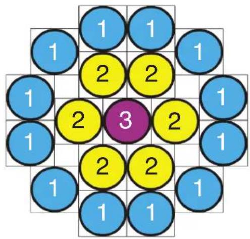
PIXEL MAP
DEFAULT DMX MAP
EXTENDED 104 CH MODE

text_image
12 1 11 18 13 2 10 17 19 14 3 9 16 15 4 8 7 6 5RGBL RINGS
EXTENDED 40 CH MODE
text_image
1 1 1 2 2 1 1 2 3 2 1 1 2 2 1 1 1 1 1RGBL COLUMNS
KLINGNET MAP
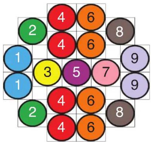
other
| Position | Value | |---|---| | 1 | 1 | | 2 | 2 | | 3 | 3 | | 4 | 4 | | 5 | 5 | | 6 | 6 | | 7 | 7 | | 8 | 8 | | 9 | 9 |RGBL ROWS
KLINGNET MAP
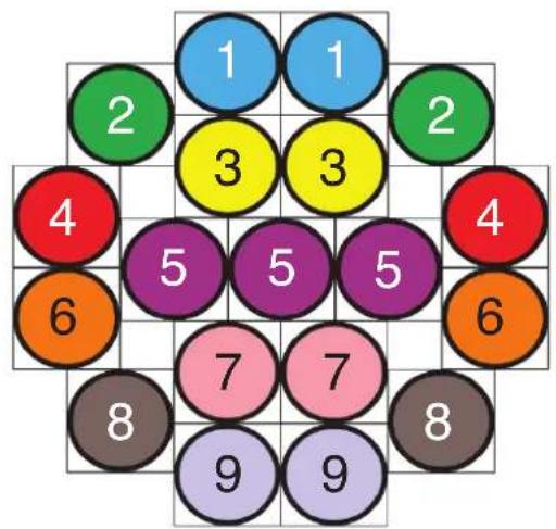
text_image
1 2 3 4 5 6 7 8 9 1 2 3 4 5 6 7 8 9COLOR WHEELS TABLE
| Value | Filter Number | Name Value | Filter Number | Name | |
| 1 | 7 | Pale Yellow | 31 | 126 | Mauve |
| 2 | 103 | Straw | 32 | 49 | Medium Purple |
| 3 | 151 | Gold Tint | 33 | 58 | Lavender |
| 4 | 100 | Spring Yellow | 34 | 199 | Palace Blue |
| 5 | 10 | Medium Yellow | 35 | 119 | Dark Blue |
| 6 | 101 | Yellow | 36 | 132 | Medium Blue |
| 7 | 104 | Deep Amber | 37 | 120 | Deep Blue |
| 8 | 15 | Deep Straw | 38 | 165 | Daylight Blue |
| 9 | 179 | Loving Amber | 39 | 161 | Slate Blue |
| 10 | 21 | Gold Amber | 40 | 118 | Light Blue |
| 11 | 105 | Orange | 41 | 68 | Sky Blue |
| 12 | 158 | Deep Orange | 42 | 143 | Pale Navy Blue |
| 13 | 22 | Dark Amber | 43 | 131 | Marine Blue |
| 14 | 778 | Millenium Gold | 44 | 115 | Peacock Blue |
| 15 | 135 | Deep Golden Amber | 45 | 172 | Lagoon Blue |
| 16 | 24 | Scarlet | 46 | 116 | Medium Blue Green |
| 17 | 106 | Primary Red | 47 | 90 | Dark Yellow Green |
| 18 | 26 | Bright Red | 48 | 139 | Primary Green |
| 19 | 27 | Medium Red | 49 | 122 | Fern Green |
| 20 | 19 | Fire | 50 | 89 | Moss Green |
| 21 | 157 | Pink | 51 | 124 | Dark Green |
| 22 | 36 | Medium Pink | 52 | 88 | Lime Green |
| 23 | 111 | Dark Pink | 53 | 138 | Pale Green |
| 24 | 128 | Bright Pink | 54 | 203 | Quarter CT Blue |
| 25 | 148 | Bright Rose | 55 | 202 | Half CT Blue |
| 26 | 332 | Special Rose Pink | 56 | 201 | FULL CT Blue |
| 27 | 793 | Vanity Fair | 57 | 200 | Double CT Blue |
| 28 | 113 | Magenta | 58 | 206 | Quarter CT Orange |
| 29 | 46 | Dark Magenta | 59 | 205 | Half CT Orange |
| 30 | 48 | Rose Purple | 60 | 204 | FULL CT Orange |
COLOR MACRO CHART
| COLOR MACRO | DMX VALUES | RED G | GREEN BLUE LIME | |
| OFF 000 | 0 0 0 0 | |||
| 1 001 | 004 80 255 234 80 | |||
| 2 005 | 008 80 255 164 80 | |||
| 3 009 | 012 77 255 112 77 | |||
| 4 013 | 016 117 255 83 83 | |||
| 5 017 | 020 160 255 77 77 | |||
| 6 021 | 024 223 255 83 83 | |||
| 7 025 | 028 255 243 77 77 | |||
| 8 029 | 032 255 200 74 74 | |||
| 9 033 | 036 255 166 77 77 | |||
| 10 | 037 - 040 255 125 74 74 | |||
| 11 | 041 - 044 255 97 77 74 | |||
| 12 | 045 - 048 255 71 77 71 | |||
| 13 | 049 - 052 255 83 134 83 | |||
| 14 | 053 - 056 255 93 182 93 | |||
| 15 | 057 - 060 255 96 236 96 | |||
| 16 | 061 - 064 238 93 255 93 | |||
| 17 | 065 - 068 196 87 255 87 | |||
| 18 | 069 - 072 150 90 255 90 | |||
| 19 | 073 - 076 100 77 255 77 | |||
| 20 | 077 - 080 77 100 255 77 | |||
| 21 | 081 - 084 67 148 255 67 | |||
| 22 | 085 - 088 77 195 255 77 | |||
| 23 | 089 - 092 77 234 255 77 | |||
| 24 | 093 - 096 158 255 144 144 | |||
| 25 | 097 - 100 255 251 153 153 | |||
| 26 | 101 - 104 255 175 147 147 | |||
| 27 | 105 - 108 255 138 186 138 | |||
| 28 | 109 - 112 255 147 251 147 | |||
| 29 | 113 - 116 151 138 255 138 | |||
| 30 | 117 - 120 99 | 0 255 | 100 | |
| 31 | 121 - 124 138 169 255 138 | |||
| 32 | 125 - 128 255 255 255 255 | |||
| 33 | 129 - 132 255 206 143 0 | |||
| 34 | 133 - 136 254 177 153 0 | |||
| 35 | 137 - 140 254 192 138 0 | |||
| 36 | 141 - 144 254 165 98 | 0 | ||
| 37 | 145 - 148 254 121 0 | 0 | ||
COLOR MACRO CHART
| COLOR MACRO | DMX VALUES | RED G | GREEN BLUE LIME | |
| 38 149 | - 152 178 1 | 7 0 0 | ||
| 39 153 | - 156 96 0 | 1 0 | ||
| 40 157 | - 160 234 1 | 39 171 0 | ||
| 41 161 | - 164 224 5 | 97 0 | ||
| 42 165 | - 168 175 7 | 7 173 0 | ||
| 43 169 | - 172 119 | 130 199 0 | ||
| 44 173 | - 176 147 1 | 64 212 0 | ||
| 45 177 | - 180 88 2 | 63 0 | ||
| 46 181 | - 184 0 | 38 86 0 | ||
| 47 185 | - 188 0 | 142 208 0 | ||
| 48 189 | - 192 52 14 | 8 209 0 | ||
| 49 193 | - 196 1 | 134 201 0 | ||
| 50 197 | - 200 0 | 145 212 0 | ||
| 51 201 | - 204 0 | 121 192 0 | ||
| 52 205 | - 208 0 | 129 184 0 | ||
| 53 | 209 - 212 | 0 | 83 | 115 |
| 54 213 | - 216 0 | 97 166 0 | ||
| 55 217 | - 220 1 | 100 167 0 | ||
| 56 221 | - 224 0 | 40 86 0 | ||
| 57 225 | - 228 209 2 | 19 182 0 | ||
| 58 229 | - 232 42 16 | 5 85 0 | ||
| 59 233 | - 236 0 | 46 35 0 | ||
| 60 237 | - 240 8 | 107 222 0 | ||
| 61 241 | - 244 255 0 | 0 0 | ||
| 62 245 | - 248 0 | 255 0 0 | ||
| 63 249 | - 252 0 | 0 255 0 | ||
| 64 253 | - 255 0 | 0 0 255 |
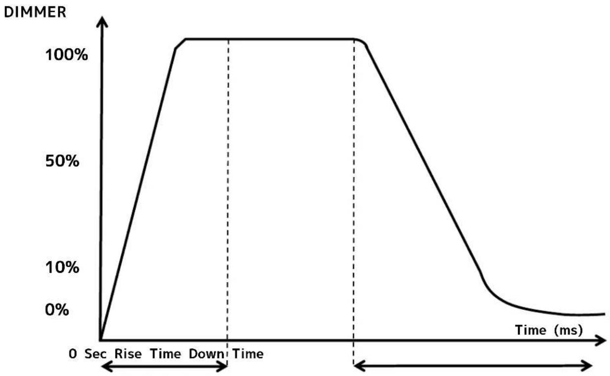
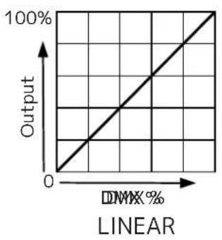
DIMMER MODES AND CURVES
line
| Time (ms) | DIMMER | | --------- | ------ | | 0 | 0% | | Rise | 50% | | Time | 100% | | Down | 100% | | Time | 100% | | End | 50% | | Time (ms) | 0% || Dimming Curve Ramp Effect | 0 sec Fade Time 1 sec Fade Time | |||
255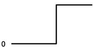 |  | |||
| Rise Time (ms) | Down Time (ms) | Rise Time (ms) | Down Time (ms) | |
| Standard (default) | 0 0 0 0 | |||
| Stage 780 1100 | 1540 1660 | |||
| TV 1180 1520 1860 1940 | ||||
| Architectural 1380 1730 2040 2120 | ||||
| Theatre 1580 1940 2230 2280 | ||||
| Stage 2 | 0 | 1100 | 0 | 1660 |
line
| DMIX % | Output | | ------ | ------ | | 0 | 0 | | 100 | 100 |
line
| DMXX % | Output | | ------ | ------ | | 0 | 0 | | >100 | 100 |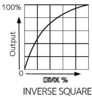
line
| DMX % | Output | |-------|--------| | 0 | 0 | | > DMX % | 100% |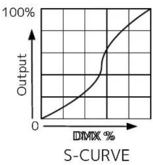
line
| DMX % | Output | |-------|--------| | 0 | 0 | | 100 | 100 |COLOR TEMPERATURE
Colors shown are an approximately representation only.
| DMX VALUE COLOR | TEMPERATURE (K) DMX VALUE | COLOR TEMPERATURE (K) | |
| 28 2800 65 6500 | |||
| 29 2900 66 6600 | |||
| 30 3000 67 6700 | |||
| 31 3100 68 6800 | |||
| 32 3200 69 6900 | |||
| 33 3300 70 7000 | |||
| 34 3400 71 7100 | |||
| 35 3500 72 7200 | |||
| 36 3600 73 7300 | |||
| 37 3700 74 7400 | |||
| 38 3800 75 7500 | |||
| 39 3900 76 7600 | |||
| 40 4000 77 7700 | |||
| 41 4100 78 7800 | |||
| 42 4200 79 7900 | |||
| 43 4300 80 8000 | |||
| 44 4400 81 8100 | |||
| 45 4500 82 8200 | |||
| 46 4600 83 8300 | |||
| 47 4700 84 8400 | |||
| 48 4800 85 8500 | |||
| 49 4900 86 8600 | |||
| 50 5000 87 8700 | |||
| 51 5100 88 8800 | |||
| 52 5200 89 8900 | |||
| 53 5300 90 9000 | |||
| 54 5400 91 9100 | |||
| 55 5500 92 9200 | |||
| 56 5600 93 9300 | |||
| 57 5700 94 9400 | |||
| 58 5800 95 9500 | |||
| 59 5900 96 9600 | |||
| 60 6000 97 9700 | |||
| 61 6100 98 9800 | |||
| 62 6200 99 9900 | |||
| 63 6300 100 10000 | |||
| 64 6400 | |||
CLEANING AND MAINTENANCE

DISCONNECT POWER BEFORE PERFORMING ANY MAINTENANCE!
CLEANING
Frequent cleaning is recommended to ensure proper function, optimized light output, and an extended life. The frequency of cleaning depends on the environment in which the fixture operates: damp, smoky, or particularly dirty environments can cause greater accumulation of dirt on the fixture's optics. Clean the external lens surface periodically with a soft cloth to avoid dirt/debris accumulation.
NEVER use alcohol, solvents, or ammonia-based cleaners.
MAINTENANCE
Regular inspections are recommended to ensure proper function and extended life. There are no user serviceable parts inside this fixture. Please refer all other service issues to an authorized ADJ service technician. Should you need any spare parts, please order genuine parts from your local ADJ dealer.
Please refer to the following points during routine inspections:
- A detailed electrical check by an approved electrical engineer every three months, to make sure the circuit contacts are in good condition and prevent overheating.
- Be sure all screws and fasteners are securely tightened at all times. Loose screws may fall out during normal operation, resulting in damage or injury as larger parts could fall.
- Check for any deformations on the housing, color lenses, rigging hardware, and rigging points
- (ceiling, suspension, trussing). Deformations in the housing could allow for dust or liquids to enter into the fixture. Damaged rigging points or unsecured rigging could cause fixture to fall and seriously injure a person(s).
• Electric power supply cables must not show any damage, material fatigue, or sediments.
NEVER remove the ground prong from the power cable.
TORQUE SETTINGS FOR SCREWS
N ORDER TO MAINTAIN THE IP65 RATING ON THE LIGHTING FIXTURES, ALL SCREWS MUST BE TIGHTENED TO THE FOLLOWING TORQUE SPECIFICATION USING A TORQUE DRIVER.
Refer to the table and diagram below for torque specifications.
TORQUE DRIVERS (Recommended): UTICA TS-30 (shown)
ALTERNATE DRIVERS:
- Proto J6107A
• Wiha 28887
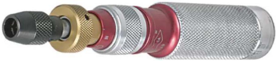
natural_image
Close-up of a metallic microphone with multiple colored connectors (no text or symbols visible)
CAUTION! DO NOT OVER TORQUE SCREWS, AS THIS CAN CAUSE LEAKAGE ISSUES!

text_image
Technical diagram of a mechanical device with numbered parts labeled 1 to 4| NO. | LOCATION QUANTITY | TORQUE | |
| 1 | Head Front Cover 8 11.3 | +0.4 Lb-in (13.0 | +0.5 Kg-cm) _ |
| 2 | Arm Cover 12 4.3 + 0.4 | Lb-in (5.0 + 0.5 Kg-cm) _ _ | |
| 3 | Carrying Handles 4 11.3 | +0.4 Lb-in (13.0 | +0.5 Kg-cm) _ |
| 4 | Base Front/Rear Covers | 16 11.3 + | 0.4 Lb-in (13.0 + 0.5 Kg-cm) |
IP TEST PARAMETERS
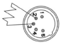
Following any repair or maintenance procedure that requires disassembly of the fixture, use ADJ's Hydro IP Tester to confirm the IP integrity of the fixture. The base air valve is located on the back panel next to the display screen, while the head air valve is located beneath the head's rear cover, as shown in the diagram below. Please contact ADJ Service for information regarding the ADJ Hydro IP Tester, or visit the product information page online at: https://www.adj.com/hydro-ip-tester.

CAUTION! THE USE OF PROTECTIVE GLOVES AND SAFETY GOGGLES IS STRONGLY RECOMMENDED WHILE PERFORMING THE IP PRESSURE TEST! AVOID PLACING YOUR FACE, EYES, HANDS, ETC IN CLOSE PROXIMITY TO THE FIXTURE'S LENS WHILE PERFORMING THE TEST!

text_image
Head Air Valve Base Air ValveDE-HUMIDIFICATION: IP65 fixtures operating in high-humidity environments may experience residual fogging or condensation. Such fogging will not damage the fixture, and can be removed using the following procedure: position the unit with the air valve pointing upwards, then open the air valve and run the unit for 1-2 hours after reaching operating temperature. Then, while the fixture is still hot, re-install the air valve and allow the unit to cool down. Please note that this procedure should be performed in a dry, air-conditioned environment. Avoid additional fogging by drying the fixture completely before placing into a road case.

natural_image
Two black plastic case boxes with visible internal components, one open and one closed (no text or symbols)| IP PRESSURE TESTING PARAMETERS | |||||
| Low Pressure Limit | High Pressure Limit | Inflation Time | Equilibrium Time | Detection Time | Acceptable Leakage |
| 2.901 psi(20.0 KPa) | 3.336 psi(23.0 KPa) | 40 sec 15 sec | 15 sec | 0.015 psi(0.1 KPa)(100 Pa) | |
ERROR CODES
| Note: Error Codes are subject to change without any prior written notice. | |
| ERROR CODES DESCRIPTION | |
| Pan Pan Motor Error | |
| Tilt Tilt Motor Error | |
| Zoom Zoom Motor Error | |
| Head Temp Head Temperature Error | |
| LED Fan 1 LED Fan 1 Error | |
| LED Fan 2 LED Fan 2 Error | |
| LED Fan 3 LED Fan 3 Error | |
| LED Fan 4 LED Fan 4 Error | |
| Humi Fan 1 Humidity Fan 1 Error | |
| Humi Fan 2 Humidity Fan 2 Error | |
| Base Temp Base Temperature Error | |
| Base Fan 1 Base Fan 1 Error | |
| Base Fan 2 Base Fan 2 Error | |
| Base Fan 3 Base Fan 3 Error |
SPECIFICATIONS
Source:
• 19 x 60-Watt RGBL LEDs (50,000 hr.)
• CRI: 84.2
- TM30 Rf: 84.7
• TM30 Rg: 99.8
• Color Temperature: 2700K \~ 10,000K
• 54,400 lux / 4.3° beam @ 16' (5m)
• 2,090 lux / 28.3° beam @ 16' (5m)
• Lumens: 17,000 (Zoomed Out, Full On)
Features:
- Moving Light Pixel Wash
• Individual Pixel Control
• Built-In Pixel Effect Programs
• Aria X2 Wireless Management System
• Electronic Strobe / Dimmer
• Pan/Tilt: 540/630 x 243 - Motorized Zoom
- Beam Angle: 5^ 38^
• Field Angle: 8° \~ 56°
• Color Calibrated Pixels so units match from batch to batch
• Virtual CMY DMX Control Modes
• Virtual Foreground and Background Color Wheel Control - Selectable LED Refresh Rates (900 Hz\~25K Hz)
- Selectable Dim Modes: Standard, Stage, TV, Arch., Theatre, Stage 2 and user settable Dim Speed (0.1S\~10S)
• 4 Dim Curves: Square, Linear, Inv. Square and S. Curve
• 0-100% smooth dimming - Fan Cooled
Colors:
• 19x RGBL LEDs (Red, Green, Blue and Lime)
• Virtual CMY DMX Control Modes
• Virtual Foreground and Background Color Wheel Control
• Built-In Color Macros
- 2,700K \~ 10,000K Linear White Color Temperature Control
• Color Temperature Presets: 2,700, 3,000, 3,200, 4,000, 4,500, 5,000, 5,600, 6,500, 8,000 and 10,000K
Control:
- 6 DMX Modes (22, 31, 40, 104, Standard CMY 31, Extended CMY 34)
• Color LCD display with 6-button function menu
• Control: DMX512, ArtNet, sACN, KlingNet and Aria X2 Wireless Management System - Built-In Effect Pixel Programs with Speed and Fade Control
• RDM (Remote Device Management) compliant - With Wired Digital Communication Network
Pan/Tilt:
• Pan: 540/630 degrees
- Tilt: 243 degrees
• 16-Bit Fine Pan & Tilt
- Pan & Tilt Locks
Connections:
- DMX Connections: IP65-rated Locking In/Out XLR Sockets
• IP65-rated Locking In/Out RJ45 Network Sockets - Power Connections: IP65-rated Locking In/Out Power Sockets
Electrical:
- Multi-voltage operation: 100-240V, 50/60Hz
- Max power consumption: 1400W (11.85Amps) @ 120V. 1350W (6.38Amps) @ 220V.
Dimensions & Weight:
- Dimensions (LxWxH): 12.5"L x 17.04"W x 20.36"H (318x433x517mm)
• Weight: 60.8lbs (27.6kg)
What's Included:
• 180mm Omega Brackets (2x)
- 1x 1.83M, IP65-rated locking power cable
- Safety Cable
Approvals / Rating:
- cETLus Pending
- CE Certified
• IP65

IP65
DIMENSIONS
Dimensions are not drawn to scale.

FCC STATEMENT
This device complies with Part 15 of the FCC Rules. Operation is subject to the following two conditions: (1) this device may not cause harmful interference, and (2) this device must accept any interference received, including interference that may cause undesired operation.
FCC RADIO FREQUENCY INTERFERENCE WARNINGS & INSTRUCTIONS
This product has been tested and found to comply with the limits as per Part 15 of the FCC Rules. These limits are designed to provide reasonable protection against harmful interference in a residential installation. This device uses and can radiate radio frequency energy and, if not installed and used in accordance with the included instructions, may cause harmful interference to radio communications. However, there is no guarantee that interference will not occur in a particular installation. If this device does cause harmful interference to radio or television reception, which can be determined by turning the device off and on, the user is encouraged to try to correct the interference by one or more of the following methods:
- Reorient or relocate the device.
- Increase the separation between the device and the receiver.
- Connect the device and the radio receiver to electrical outlets on two different circuits.
- Consult the dealer or an experienced radio/TV technician for help.