S902 - TV Decoder GeoBox - Free user manual and instructions
Find the device manual for free S902 GeoBox in PDF.

| Type | TV Decoder |
| Brand | GeoBox |
| Model | S902 |
| Dimensions (approx.) | 15.0 x 10.0 x 3.0 cm |
| Weight (approx.) | 0.3 kg |
| Power Supply | DC 5V/1A |
| Power Consumption | < 10 W |
| Video Output | HDMI (4K UHD), AV (composite) |
| Audio Output | HDMI, Digital Optical, Analog RCA |
| Connectivity | Ethernet RJ45, Wi-Fi 802.11 b/g/n |
| USB Ports | 2 x USB 2.0 |
| Storage | Supports external USB storage |
| Supported Video Formats | MPEG-2, MPEG-4, H.264, H.265 |
| Supported Audio Formats | MP3, AAC, AC3 |
| Maximum Resolution | 4K UHD (3840x2160) |
| Operating System | Linux-based |
| Remote Control | Infrared (IR) |
| Languages | Multiple languages supported |
| Accessories Included | Remote control, power adapter, HDMI cable, user manual |
| Safety Certifications | CE, RoHS |
| Repairability | Modular design; spare parts available |
Frequently Asked Questions - S902 GeoBox
User questions about S902 GeoBox
0 question about this device. Answer the ones you know or ask your own.
Ask a new question about this device
Download the instructions for your TV Decoder in PDF format for free! Find your manual S902 - GeoBox and take your electronic device back in hand. On this page are published all the documents necessary for the use of your device. S902 by GeoBox.
USER MANUAL S902 GeoBox
4x2 UHD Quad View Processor with Seamless switcher
4x HDMI 2.0 input and dual UHD outputs
Maximum input: 4096*2160 @60Hz, 4:4:4 chroma sampling
with the same or different display Windows in each output
Multiple display windows with flexible image size, cropping, location and overlap
Seamless switching in single or multi-view display modes.
Image fade in, fade out, dissolve, and wipe
True 10-bit processing and up/down scaling.
Sales & Technical support
Website : www.VigilLink.com
E-mail : info@vigillink.com
Version:1.02
Tel: +949-701-4742
Table of Contents
Introduction 3
Outlook
Front panel.... 4
Back panel ....5
System Connection 6
Content in the packing box....7
User Guide
1. How to use IR Remote Controller.... 7
1.1. P-100 Controller for User Preset Modes Recall ....7
1.2. RC-902 Controller for System Setup.... 8
1.3. Limitation in OSD Operation....9
1.4. IR Receiver Extender.... 9
1.5. OSD Lock and Unlock.... 9
1.6. OSD Menu keypads on the Front Panel....9
2. System Structure ...... 10
2.1. OSD Menu location....10
2.2. Display Window 10
2.3. Output Ports 10
2.4. Limitations in Output Port...... 10
3. System Reset
3.1. Complete System Reset through RESET HOLE.... 10
3.2. Reset Through IR Controller or OSD.... 10
4. System Control 11
4.1. Control Method ...... 11
4.2.RS232....11
4.3. Ethernet Connection.... 11
5. System Data SAVE and Backup/Restore in PC.... 11
6. OSD MENU Structure.... 12
6.1. OUTPUT SETUP 12
- OUTPUT MODE 12
- INPUT SELECT.... 12
- AUDIO SELECT 12
- RESOLUTION 12
- TRANSITION / DURATION.... 13
- PRIORITY (OUTPUT 1 / OUTPUT 2).... 13
- HDCP 13
6.2. WINDOW SETUP 14
- INPUT SELECTION 15
- SCALING 15
- WINDOW....15
- PICTURE.... 15
- COLOR.... 16
- DE-INTERLACING.... 16
- NOISE REDUCTION 19
- MISCELLANEOUS 19
6.3. SYSTEM 20
- PROFILE.... 20
- EDID 20
- OSD....20
- STANDBY 21
- ETHERNET 21
- RS232 21
- BOX ID 21
- NAME 21
- RESET 21
- VERSION 21
7. S902 Control TOOL (SCT) & Web UI 22
8. Call for technical support 26
9. Safety Precaution and Maintenance 26
10. Warranty and RMA policy 27
10.1. Warranty.... 27
10.2. RMA Policy 27
Specifications.... 28
Disclaimer/Copyright statement 29
Warranty/RMA and FCC/CE statement.... 29
Revision history 30
Introduction
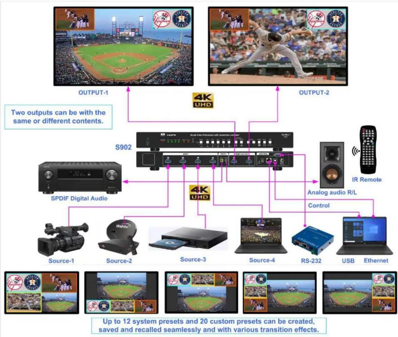
The S902 is a 4x2 UHD Quad-View processor that allows users to display up to four 4k/60 sources simultaneously on one or two UHD displays. This device offers a highly flexible and cost-effective solution for routing up to four 4k/60 sources to two separate displays simultaneously. Users can choose from 12 default multi-view layout presets and 20 custom Profile Presets to customize their display mode.
Featuring 4 HDMI 2.0 inputs and 2 HDMI 2.0 outputs, the S902 supports CEA video standard timings up to 4096*2160 @60Hz with 4:4:4 chroma sampling. Each output port can accommodate up to 4 windows, with each window capable of selecting an input source from any input port. Users have the option to assign the same input source to multiple windows and can adjust input selection, image positioning, resizing, cropping, and color settings for each window.
Users can prioritize display windows when they overlap and select one or multiple windows with the same configuration for any output port. The device offers 16 transition modes, including high speed seamless switching, Fade-in, Fade-out, Dissolve, and Wipe, with selectable duration for transitions. It integrates HDMI embedded audio, RCA SPDIF digital audio, and analog 3.5mm R/L audio jack R/L, allowing users to assign audio from input ports to each audio output port as needed.
Control options for the unit include IR controller, front panel push button, USB, WebUI, RS232 and Ethernet, providing versatile control methods for various applications. Users can recall up to 20 custom Profile Presets through different control systems. Designed for continuous operation in a 24/7 environment, the S902 offers easy configuration, low entry barriers, cost-effectiveness, reliability, and flexibility for a wide range of applications.
Application
- Front end processor for large display, such as LED, edge blending system, video wall.
- Digital signage
– Presentation halls
– Security & surveillance systems - Education
– Conference room
– Video content post production
– Video editing studio
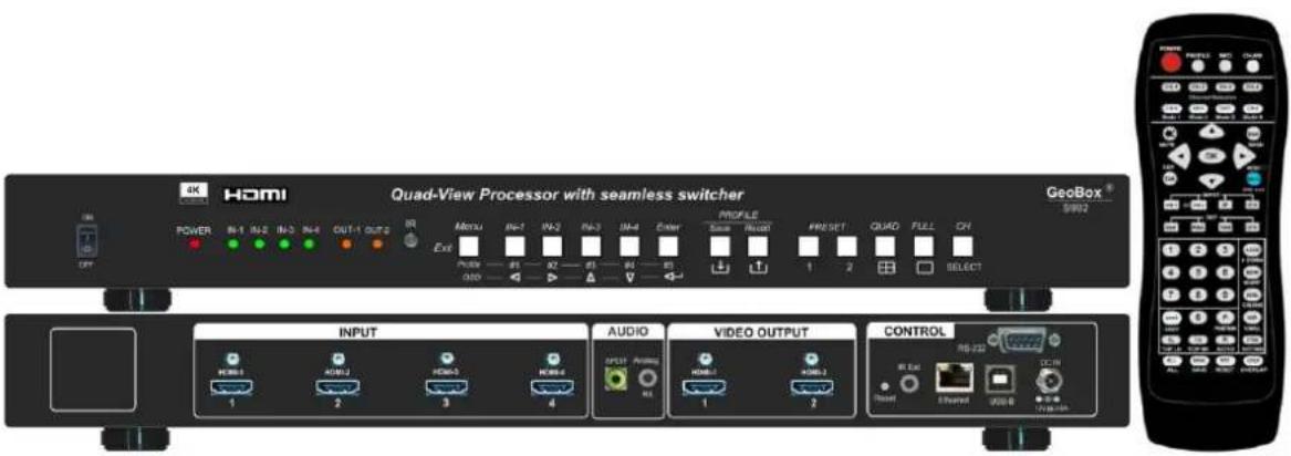
Outlook
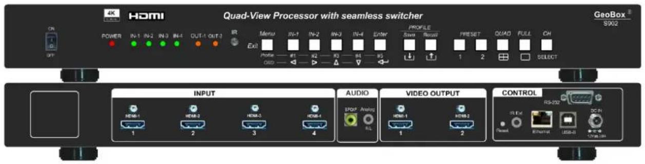
Front panel
- Input LED will show RED light when S902 detects signal source signal in that input port. Once it had been selected to show on the Window, it will turn to GREEN light.
- When turn-off Power by IR controller, the power LED will turn to RED. User can power up by IR Controller (P-100 or RC-902) or power switch.
- The function in CH/SELECT key is changed to OSD LOCK key.
- Preset-1/Preset-2 keys is to recall system Preset-1 and Preset-2 with one window in Left and 3 windows in the Right side. One is PIP another is POP.
- Profile Save: it will show "SAVE PROFILE" message. User can select Profile #1 to #5 key on front panel to save this Custom Profile.
- Profile Recall key will show "LOAD PROFILE" message. User can recall Profile #1 to #5 directly.
- These Custom Profile #1 to #5 are the same Profile Index as that inside OSD menu.
- When power LED is blinking, the OSD menu had been locked.
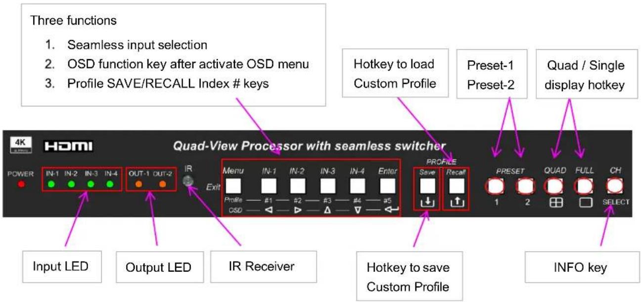
Back panel
User can connect signal source to any of the input ports for two output ports.
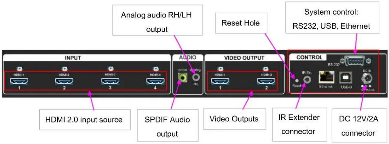
- OSD Menu can only show in Output-1 channel.
- Window-1 and Window-2 will have full functions OSD menu. "De-Interlacing" and "Noise Reduction" OSD menu will only be available in Window-1 and Window-2.
- Except OSD Menu difference, Window-3 and Window-4 will have the same function and video quality as Window-1 and Window-4.
- User can select audio source for each output port, SPDIF and Analog R/L output independently.
- Every input signal source (HDMI-1 to HDMI-4) can be assigned to one or multiple Windows.
System Connection
Each display Window can select signal from any input port. Each output can display up to 4 windows. Each window can be located at any position with flexible resizing, cropping, aspect ratio, color correction and overlap priority setting.
flowchart
graph TD
    A["OUTPUT-1"] --> B["S902"]
    C["OUTPUT-2"] --> B
    D["IR Remote"] --> E["Analog audio R/L"]
    E --> F["Control"]
    G["4K UHD"] --> H["4K UHD"]
    I["SPDIF Digital Audio"] --> J["Source-1"]
    I --> K["Source-2"]
    I --> L["Source-3"]
    I --> M["Source-4"]
    I --> N["RS-232"]
    I --> O["USB"]
    I --> P["Ethernet"]
    Q["UP to 12 system presets and 20 custom presets can be created, saved and recalled seamlessly and with various transition effects."] --> B
Output ports configuration
➢ OSD can only be showed in Output-1.
User can assign any display Window for each output. Maximum is 4 windows.
If any Window is assigned to both output ports, the Window content, layout and position must be the same.
If each output shows different Windows, user can flexibly manipulate the Windows without affecting another Output port.
Content in the packing box
The S902 Quad View Processor
1x RC-902 IR Controller
1x IR Extending Receiver with 1.8m cable
1x AC to DC Power supply unit with Power Cord
Mounting bracket with screw (Option)
P-100 Profile Control IR Controller (Optional)
Please download User Guide & Web UI Tool at www.vnstw.com.
User Guide
1. How to use IR Remote Controller
- RC-902 is standard controller for system setup.
- P-100 is simplified controller for end user. The operation will not affect system Setup. It is an option item to buy separately.
1.1. P-100 Controller for User Preset modes recall
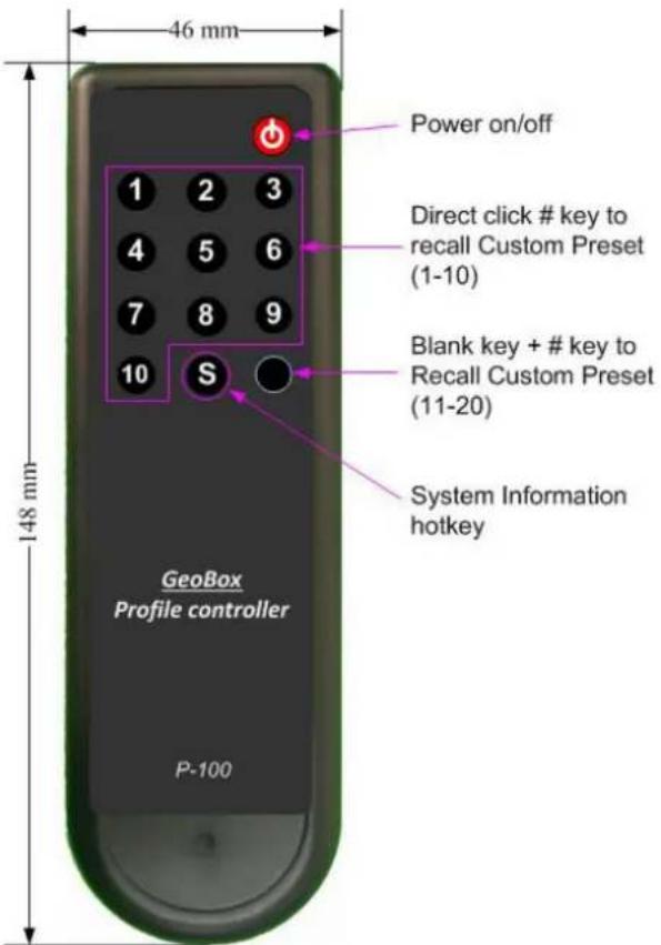
- Directly click number keys 1-10 will recall Custom Profile 1-10.
- If click Blank key first, then click other number key, it can recall Custom Profile 11-20.
- Click "S" key will pop-up Input/Output and FW version system information.
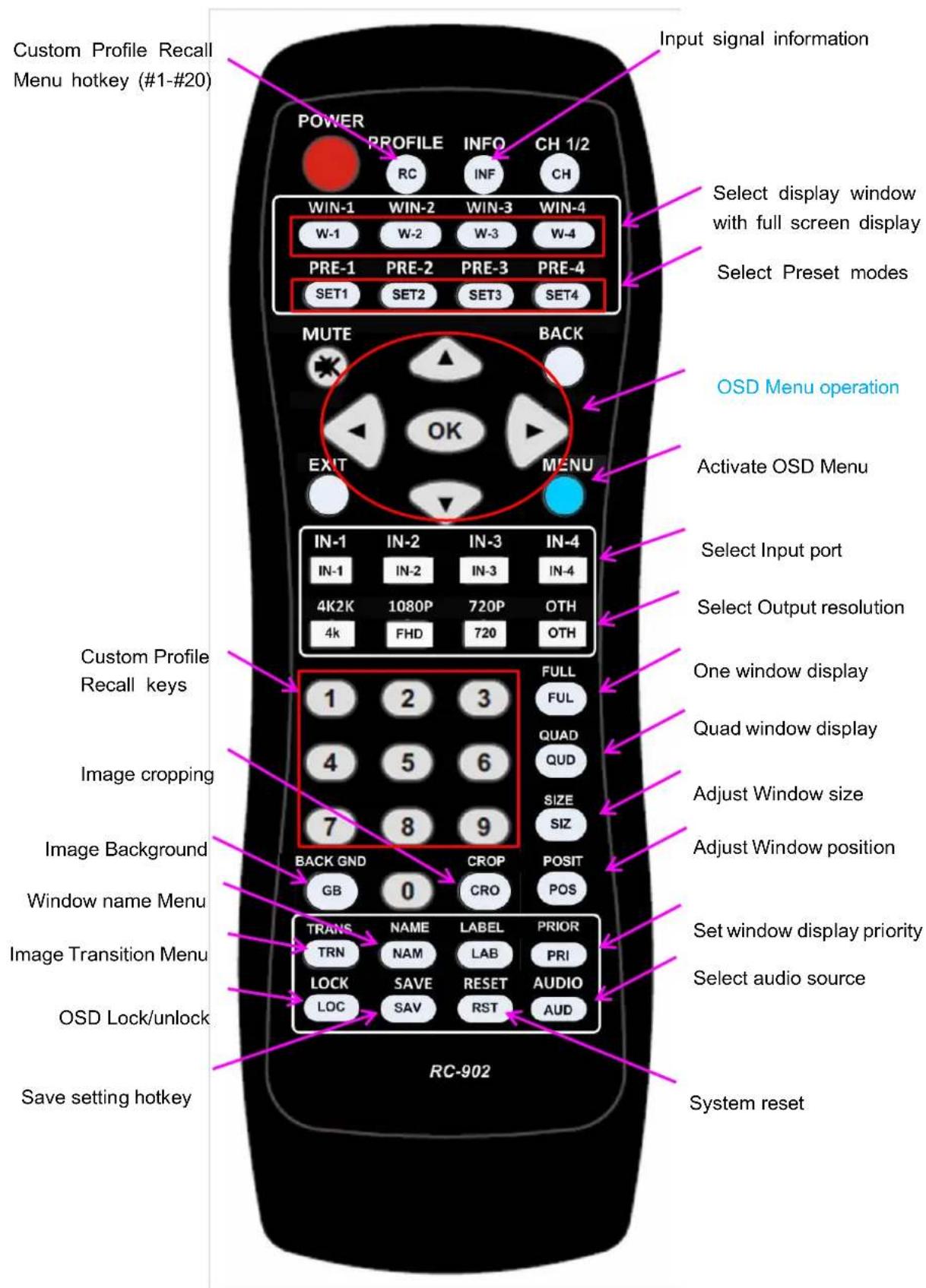
1.2. RC-902 Controller for system Setup
1.3. Limitation in OSD Operation
OSD Menu can only show in Output-1 channel.
Window-1 and Window-2 will have full function OSD menu. "De-Interlacing" and "Noise Reduction" OSD menu will only be available in Window-1 and Window-2.
User can select audio source for each output HDMI, SPDIF and Analog R/L output independently.
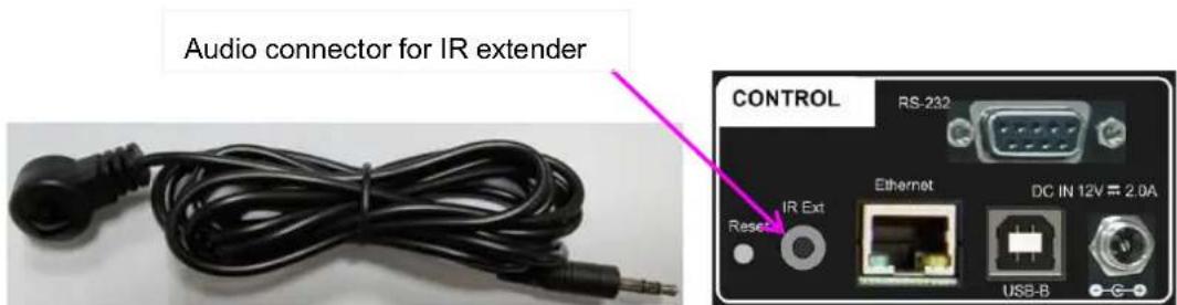
1.4. IR Receiver Extender
RC-902 controller is specific for the operation of S902.
IR receiver is on Front Panel. One 3.50 mm audio connector for IR extender is located at Back Panel of S902. 1.8m IR extension cable is equipped in the packing. User can add 2.50 audio cable to extend the control distance up to 20 meters.
1.5. OSD Lock and Unlock
To press LOCK key on RC-902 controller for 5 seconds will LOCK the OSD. [Menu Lock] message will show on the screen. To press another 5 seconds on LOCK key, it will UNLOCK the OSD. [Menu Unlock] message will show on the screen.
On front panel, MENU key has the same function as LOCK key in IR controller.
OSD Lock can also be used while multiple units of GeoBox are used simultaneously to prevent mutual interference.
When OSD is locked, Power LED on front panel will be blinking.
1.6. OSD Menu keypads on the Front Panel
Front panel has OSD keypads. The functions are the same as IR controller. The only difference is in the hotkeys function. Please see more details in "Front Panel" section.
2. System structure
2.1 OSD Menu location
- OSD will only display on Output-1.
- OSD menu is location at top left corner.
2.2 Display Window
- One output can display up to 4 Windows.
- Each Window can select signal source from any HDMI input port.
- Each Window has independent color correction and settings.
- One HDMI signal can be assigned to multiple Windows.
2.3 Output ports
- One output can display up to 4 Windows.
- Each Window can select signal from any HDMI input port.
2.4 Limitations in output display
- OSD can only be showed in Output-1
- Each output can display up to 4 Windows.
- The Window position, size and cropping in two output ports will be the same.
- User can select different Windows for each output with different setup.
- If each output shows different Windows, user can have flexible Windows setup without affecting another Output port.
- Window-3 and Window-4 will have no de-interlacing function. It will execute double scaling for interlaced signal. We suggest using progressive signal to get the best video quality.
3. System Reset
3.1. Complete system reset through RESET hole
- Inserting small pin into RESET hole on back panel for 5 seconds will reset the system to default settings. It will erase all Custom Preset Profile data.
3.2. Reset through IR controller or OSD
- User can Reset through OSD menu under [System]→ [Reset].
- Click IR control [RESET] key will Pop-Up System Reset OSD menu.
- Custom Profile Data will remain the same without being erased.
4. System Control
4.1. Control method
- User can control S902 through IR controller, front panel keypads, USB, RS232 and Ethernet.
- S902 control tool is available for USB control and WebUI is embedded in S902 for Ethernet control.
4.2. RS232
RS232 interface is designed with DB-9 connector. User can select 11520 or 9600 baud rates.
The UART Protocol between GeoBox and a Host computer can be downloaded from website. The protocol can be executed via RS-232, Ethernet or other forthcoming communication methods.
Box ID is available from OSD setting when multiple units are used at the same time.
4.3. Ethernet connection
User can control and setup S902 through network connection and embedded WebUI.
UTP cable can be used for direct connection between PC and GeoBox. User needs to set PC TCP/IPv4 with the same domain segment as GeoBox (for instance, to set IP address at (192.168.0.105) and subnet mask at (255.255.255.0).
Open web browser (Google Chrome or Internet Explorer) and input S902 IP address (default is 192.168.0.100), user can see GeoBox WebUI and menu for further system operation. There is no additional software is required.
If user can't connect the network, please power off/on S902 again to let PC detect S902 network.
If the connection is gone through WiFi router or switch/hub through RJ45 to Lan port, user can set DHCP IP or Static IP for the connection.
If necessary, please [Renew] DHCP to get IP address for network connection.
Each S902 can set different IP address for independent operation and control.
If S902 is connected with WiFi Router (through LAN port), user can control S902 through WiFi via PC, iPad or mobile phone through the same SSID.
User can set different IP in each S902 for individual control while multiple units are used.
Default TCP server port is 1266.
5. System data SAVE and Backup/Restore in PC
To use SAVE hotkey and select Index # to store custom setting through OSD.
System data backup and restore in PC should be done through SCT control tool.
6. OSD Menu structure
6.1. OUTPUT SETUP
Below is the menu under OUTPUT SETUP:
| Output mode | FULL, QUAD, PRE-1 to PRE-10 | |
| Input select | WIN-1 | OUTPUT-1, OUTPUT-2, BOTH, OFF |
| WIN-2 | ||
| WIN-3 | ||
| WIN-4 | ||
| Audio select | OUT-1 | Win-1, Win-2, Win-3, Win-4, Mute |
| OUT-2 | Win-1, Win-2, Win-3, Win-4, Mute | |
| COAXIAL | Win-1, Win-2, Win-3, Win-4, Mute | |
| Resolution | 1920x1080P60, 1920x1080P50, 3840x2160P60, 3840x2160P50, 3840x2160P30, 3840x2160P25, 3840x2160P24, 1280x720P60, 1280x720P50, 4096x2160P60, 4096x2160P50, 3840x2160P59.94, 1920x1080P59.94, 1280x720P59.94 | |
| Transition | Seamless, Fade Out/In, Dissolve, Wipe/Left, Wipe/Right, Wipe/Top, Wipe/Bottom, Wipe/Center1, Wipe/Center2, Wipe Center3, Wipe/Shuttle1, Wipe/Shuttle2, Wipe/Shuttle3, Wipe/Top-L, Wipe/Top-R, Wipe/Bottom-L, Wipe/Bottom-R | |
| Duration | To set the time of transition | |
| Priority (Out1) | INITIAL | 1234 |
| LAYER 2 | 2134 | |
| LAYER 3 | 3214 | |
| LAYER 4 | 4321 | |
| Priority (Out2) | INITIAL | 1234 |
| LAYER 2 | 2134 | |
| LAYER 3 | 3214 | |
| LAYER 4 | 4321 | |
| HDCP | AUTO, ON, OFF | |
OUTPUT MODE
12 output modes can be selected, including single Window full screen display and Quad Window display.
▶ INPUT SELECT
- Each HDMI input signal can be assigned to any display Window.
- Each Window can be assigned to Output-1, Output-2, Both or turn off.
AUDIO SELECT
User can select from 4 input sources audio for Output-1, Output-2, SPDIF output or Analog output. Analog output audio is abstracted from SPDIF audio.
RESOLUTION
- User can select output resolution from 14 preset resolutions.
- Two output channels will have the same output resolution.
- 18 transition effects are built in the processor. It includes Quick Seamless, Fade in/Fade out, Dissolve and Wipe.
- Transition effect only implemented during input source or display mode change.
- Each effect can select different duration.
- User can save Transition setting in Custom Profile mode together with input selection and Window configuration. When selects this Preset mode, user will see Transition effect.
- Fade-in/Fade-out can be executed in both single and multiple Windows display modes. Dissolve and Wipe transition modes can only be executed with single Window display.
- The duration range in different Transition modes may be different.
➢ PRIORITY (OUTPUT 1 / OUTPUT 2)
To set each window display priority when they are overlapped. Each Window can be at different layer. User can use WebUI to select Priority for each Window freely. Each Output can be set independently through OSD.

natural_image
Collage of four photos: Eiffel Tower, pink flowers, Windows logo, and sunset over water (no text or symbols)HDCP
- AUTO: When the input is HDCP compliant, the box will execute HDCP control in both input and output.
- ON: no matter input is HDCP compliant or not, it will always control HDCP.
- Off: When the input is HDCP compliant and the output is not HDCP compliant, the processor will turn off output display.
6.2. WINDOW SETUP
WINDOW-1/WINDOW-2: with full function of OSD menu.
WINDOW-3/WINDOW-4: No DE-INTEERLACING and NOISE REDUCTION OSD Menu.
| Input Select | HDMI-1 | |
| HDMI-2 | ||
| HDMI-3 | ||
| HDMI-4 | ||
| Scaling | RATIO | FULL, ASPECT |
| CROP H-START | ||
| CROP V-START | ||
| CROP H-END | ||
| CROP-V-END | ||
| ASPECT H-POS | ||
| ASPECT-V-POS | ||
| RESET | NO/YES | |
| WINDOW | H-POS | |
| V-POS | ||
| WIDTH | ||
| HEIGHT | ||
| LEFT POS | ||
| TOP POS | ||
| PICTURE | FORMAT | RGB, YUV444, YUV422, YUV420 |
| BRIGHTNESS | ||
| CONTRAST | ||
| H-SHARPNESS | ||
| V-SHARPNESS | ||
| HISTOGRAM | ||
| COLOR | CHROMATICITY | |
| HUW | ||
| COLOR TEMP | 6500K, 9300K | |
| GAMMA1 MODE | Gamma 1.0, Gamma 1.8, Gamma 2.2, Gamma 2.6 | |
| GAMMA2 MODE | Gamma 1.0, Gamma 1.8, Gamma 2.2, Gamma 2.6 | |
| COLOR CORRECTION | BLUE 1-4, GREEN 1-4, SKIN TONE 1-4 |
| DE-INTERLACING | ON/OFF | ON/OFF |
| ENABLE 2:2 PD | ON/OFF | |
| 2:2 PD time | 1-15" | |
| ENABLE 2:3 PD | ON/OFF | |
| 2:3 PD TIME | 1-15" | |
| MOTION DETECTION | LEVEL 1 TO LEVEL 5 | |
| DIAGONAL CORRECT | 1-3 | |
| 24PSF MODE | ON/OFF | |
| NOISE REDUCTION | HORIZONTL | 0-3 |
| VERTICAL | 0-3 | |
| TEMPORAL | 0-3 | |
| BLOCK | 0-3 | |
| MOSQUITO | 0-3 | |
| COMBING | 0-3 | |
| MISCELLANEOUS | UP-SIDE DOWN | ON/OFF |
| HORIZONTAL FLIP | ON/OFF | |
| FREEZE | ON/OFF | |
| BACKGROUND COLOR | BLACK/BLUE |
▶ INPUT SELECTION
- Each Window can select any input signal source from HDMI-1 to HDMI-4.
- Each HDMI input signal can be assigned to multiple Windows.
> SCALING
- RATIO:
- FULL: To show image with full Window.
- ASPECT: To show image with source original aspect ratio.
- Different selection will affect Window size and position adjustment.
- CROP:
To adjust image Horizontal and Vertical Start and End points coordinates.
- It can crop any location of the source image in each Window.
- IR controller CROP Hotkey can only ZOOM-IN / ZOOM-OUT source image from the center.
- ASPECT H-POS / V-POS: When the image is not full screen display in the Window, user can adjust the image position based on the same aspect ratio through this function.
- RESET: To reset the image to default setting in all functions under SCALING.
> WINDOW
- H-POS / V-POS: To adjust Horizontal and Vertical positions of the image. The image will keep the same aspect ratio.
- WIDTH: To adjust the image location in Right Edge with Left Edge at fixed location. It can change image horizontal aspect ratio. If will be affected by SCALING selection.
- HEIGHT: To adjust the image location in Bottom Edge with Top Edge at fixed location. It can change image vertical aspect ratio. If will be affected by SCALING selection.
- LEFT POD: To adjust image Left Edge position with Right Edge at fixed location. It can change horizontal aspect ratio. If will be affected by SCALING selection.
- TOP POS: To adjust image Top Edge position with Bottom Edge at fixed location. It can change vertical aspect ratio. If will be affected by SCALING selection.
- IR controller POSIT and SIZE hotkeys can implement the same function.
PICTURE
- FORMAT: To show input source Format.
- BRIGHTNESS, CONTRAST, H-SHARPNESS, V-SHARPNESS
- HISTOGRAM: To show image histogram at real time.
COLOR
- Color adjustment for Chromaticity color gain, Hue, Color Temperature (6500k/9300k)
- GAMMA1 MODE: input signal gamma curve selection.
- GAMMA2 MODE: output signal gamma curve selection. The vision feeling change in low brightness image will be more obvious.
- COLOR CORRECTION: Blue, Adjust color gain in Blue, Green and Skin Tone.
DE-INTERLACING (Pictures from Genesis Microchip)
- This function is for user to select different de-interlacing method in video editing.
- The major application is for interlaced signal source such as 2160i, 1080i, 480i... which user can only see odd frame or even frame in one time. Properly conversion of interlaced signal into progressive signal will get the best video quality especially in motion picture.
- When de-interlacing is turned off, it will implement double scaling to fulfil complete video frame.
- Below are some examples:
ODD Field

natural_image
Pixel art illustration of the Colosseum in Rome with a blue road and distant sun (no text or symbols)EVEN Field

natural_image
Pixel art illustration of a cityscape with ancient columns, a stone arch, and a blue path leading to a distant figure (no text or symbols)
Correct Pairing

natural_image
Cartoon illustration of a man walking past the Colosseum with columns and a sun in the background (no text or symbols)- Motion picture field pairing (2:3/2:2 Pull Down):
24 frames/second film transferred to 60/50 frames video:
2:3 Pull-Down: 1 ^st frame→2 frames, 2 ^nd Frame→3 frames, 2→5, 24→60
○ 2:2 Pull Down: increase film speed to 25 frames/second, then each frame transferred to 2 frames video. 2→4, 25→50
Incorrect 2:3/2:2 Pull Down

natural_image
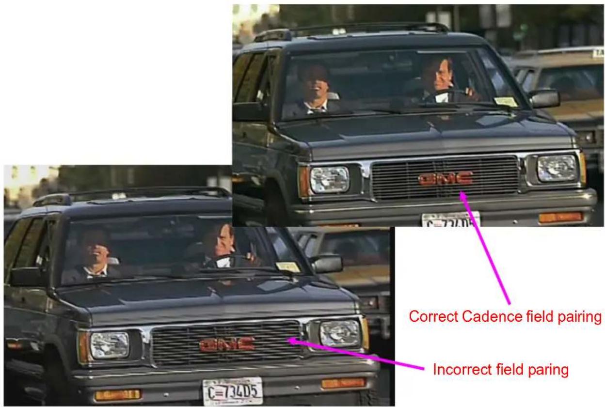
Red car wheel moving on gravel ground with blurred background (no visible text or symbols)Correct 2:3/2:2 Pull Down

natural_image
Red sports car driving on gravel ground with grassy slope in background (no visible text or symbols)Diagonal Processing:
Without Diagonal Correction
With Diagonal Correction

natural_image
Close-up of a waving American flag with blue stars and white stripes (no text or symbols visible)
natural_image
Close-up of a waving American flag with blue stars partially visible (no text or symbols)With correct cadence

natural_image
Exterior view of a large stadium with blue and orange roof tiles, featuring a red racing car on the track (no signage or text visible)Without correct cadence pairing

natural_image
Exterior view of a large stadium with blue and orange roof tiles, featuring a red racing car on the track (no signage or text visible)PS. Usually, the default is to turn on all functions under DE-INTERLACING. In some Lab, user can turn on/off some functions to verify the type of the video source (such as the video is 3:2 or 2:2 Pulldown) for further video editing. It can also be used in the school for video teaching class to under different video functions.
NOISE REDUCTION
- The video content may come from different signal sources, such as PC, video camera, DVD, broadcasting, de-compressed video, de-compressed image... Each signal source may preserve different types of noise.
- S902 allows user to select different reduction type to execute the best noise reduction effect based on different video content.
- Only available in Window-1 and Window-2.
MISCELLANEOUS
- S902 doesn't have image 90/270 degrees rotation function and only can do UP-SIDE DOWN and HORIZONTAL FLIP.
- FREEZE is to stop the video at some specific point.
- BACKGROUND COLOR: only Black and Blue color background can be selected at this moment. Customized color or pattern will be added in the future.
6.3. SYSTEM
Below are OSD structure under SYSTEM.
| PROFILE | LOAD | PROFILE 1- PROFILE 20 |
| SAVE | PROFILE 1- PROFILE 20 | |
| EDID | HDMI-1 | 3840/2160-60, 3840x2160-30, 1920x1080-60, 1024x769-60, 1280x720-60, 1280x800-60, 1920x1200-60, 2560x1440-60, 2560x1600-60, 3840x1080-60, 3840x2400-60, 3840x2400-30 |
| HDMI-2 | ||
| HDMI-3 | ||
| HDMI-4 | ||
| OSD | TRANSPARENT | 0-100% |
| TIME-OUT | OFF-120 | |
| STANDBY | OFF-300 | |
| ETHERNET | STATIC | IP ADDRESS, SUB MASK, DEFAULT GATEWAY |
| HDCP | IP ADDRESS, SUB MASK, DEFAULT GATEWAY | |
| RS232 | 115200/9600 | |
| BOX ID | 0-99 | |
| NAME | WINDOW-1 | |
| WINDOW-2 | ||
| WINDOW-3 | ||
| WINDOW-4 | ||
| HDMI-1 | ||
| HDMI-2 | ||
| HDMI-3 | ||
| HDMI-4 | ||
| RESET | ||
| RESET | YES/NO | |
| VERSION | FW VERSION |
PROFILE
- LOAD: Load custom Profile from PROFILE 1 - PROFILE 20.
- SAVE: Save custom Profile to PROFILE 1 - PROFILE 20.
EDID
- Each input port can select different EDID.
- 12 preset EDID can be selected for each input port.
> OSD
- User can set OSD transparent effect from 0-100%.
- OSD turn off time can be from 0-120 seconds. When select "0", the OSD will not disappear until touch OSD keypad or system mode change.
STANDBY
- When no input signal, S902 will turn off output signal and get into sleeping mode.
- Once input signal is detected, the system will turn on automatically.
- The time to get into sleeping mode is from 0-300 seconds. When select "0", the system will maintain active without turn off output signal.
ETHERNET
- STATIC:
Default static IP address is 192.168.0.100. User can open PC Chrome or Edge and input S902 IP address to get WebUI for system control. - User can change IP address, Subnet Mask and Default Gateway manually.
- DHCP: User can also select DHCP when the system is connected with Ethernet switch/hub or router.
- After connection, user can will see WebUI to execute S902 system setup and control. The same network segment setting in PC is required if connect PC and S902 directly with UTP cable.
- Apple Mac or iPad can be used for the control of S902 through network connection.
RS232: Two baud rates can be selected for RS232 control: 115200 and 9600.
BOX ID
- BOX ID is designed for independent GeoBox control in RS232 command. User can set different IP address in Ethernet to control multiple units of GeoBox.
- The range from BOX ID is from 0-99.
NAME
- User can change the name in WINDOW 1-4 and input ports HDMI 1-4.
- The maximum digital of the name is 10. Text, symbol and number are available for selection.
- User can reset the setting through RESET key under this menu.
RESET
- User can reset the system to default setting. Customer PROFILE will not be erased.
- User can also reset the system through RESET hole on the back panel. Please insert small pin into RESET hole for 5 seconds and "Factory Reset" will show up. This reset will erase all custom Profile data and the system will return to Factory Default at the same time.
> VERSION
To show up Firmware Version of the system
7. S902 Control Tool (SCT) & Web UI
S902 can be controlled through SCT through USB. The PC needs to support Web HID interface. Below is the compatibility list at this moment. Chrome/Edge/Opera can fully support it.
| ☐ | ☐ | ||||||||||
| Chrome | Edge | Firefox | Opera | Safari | Chrome Android | Firefox for Android | Opera Android | Safari on iOS | Samsung Internet | WebView Android | |
| HID | √ | √ | ✗ | √ | ✗ | ✗ | ✗ | ✗ | ✗ | ✗ | ✗ |
| 89 | 89 | No | 75 | No | No | No | No | No | No | No | |
| connect event | √ | √ | ✗ | √ | ✗ | ✗ | ✗ | ✗ | ✗ | ✗ | ✗ |
| 89 | 89 | No | 75 | No | No | No | No | No | No | No | |
| disconnect event | √ | √ | ✗ | √ | ✗ | ✗ | ✗ | ✗ | ✗ | ✗ | ✗ |
| 89 | 89 | No | 75 | No | No | No | No | No | No | No | |
| getDevices | √ | √ | ✗ | √ | ✗ | ✗ | ✗ | ✗ | ✗ | ✗ | ✗ |
| 89 | 89 | No | 75 | No | No | No | No | No | No | No | |
| requestDevice | √ | √ | ✗ | √ | ✗ | ✗ | ✗ | ✗ | ✗ | ✗ | ✗ |
| 89 | 89 | No | 75 | No | No | No | No | No | No | No | |
(Document from MDN Web Docs)
WebUI is another control tool that is embedded inside S902 and need to connect through network. It can be used in any web browser. The outlook and operation of these two control tools are similar and SCT tool may have some functions that WebUI hasn't. If direct Network connection is required with UTP cable, please set the same Network segment in PC.
7.1. Open S902 Control Tool (SCT) and WebUI
SCT Tool:
- Click SCT to open the tool. It will show up Control Window.
- Click [Connect] button and select USB for the connection.
WebUI:
- User can also use all kind of Web Browser and S902 IP address to access WebUI.
Please change IPV4 setting to get the same Network segment and input S902 IP address for the connection. User will see WebUI control Window for further operation. Apple Mac and iPad can also be used in WebUI control tool.
flowchart
graph TD
    A["Connect"] --> B["OUTPUT SETUP"]
    C["Refresh"] --> B
    B --> D["PROFILE"]
    B --> E["Window Setup"]
    B --> F["System"]
    B --> G["Information"]
    B --> H["Firmware Update"]
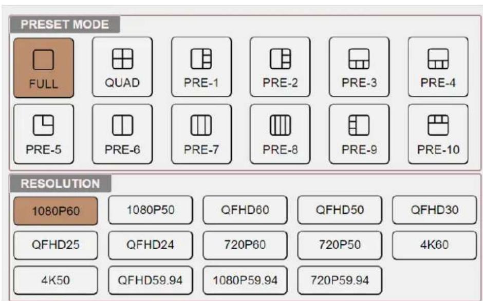
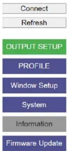
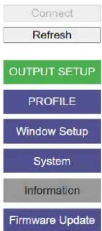
7.2. After click OUTPUT SETUP, user can see below window to select system preset mode and output resolution for two outputs at the same time. If user wants to select windows for different outputs, please use OSD to do the setup.
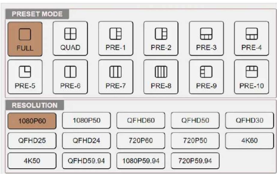
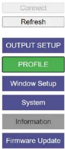
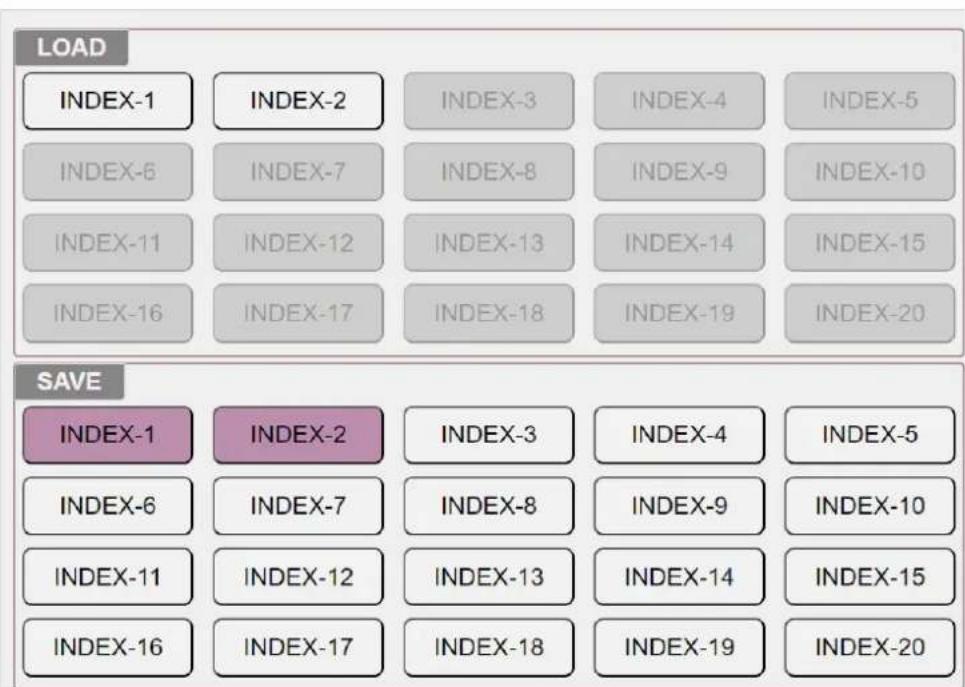
7.3. When click PROFILE button, user will see below window and SAVE or LOAD custom Preset Mode in Index-1 to Index-20. The Index will be highlighted when it has been stored with Profile Data.
flowchart
graph TD
    A["Connect"] --> B["Refresh"]
    B --> C["OUTPUT SETUP"]
    C --> D["PROFILE"]
    D --> E["Window Setup"]
    E --> F["System"]
    F --> G["Information"]
    G --> H["Firmware Update"]
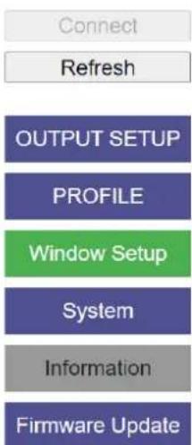
7.4. WINDOW SETUP allows user to select input source, set overlap priority and set Window position, size and aspect ratio freely.
flowchart
graph TD
    A["Connect"] --> B["Refresh"]
    B --> C["OUTPUT SETUP"]
    C --> D["PROFILE"]
    D --> E["Window Setup"]
    E --> F["System"]
    F --> G["Information"]
    G --> H["Firmware Update"]
![- Click [Refresh] button to let operation window match actual layout of the windows. - Click and hold to draw the Window position. - Click and hold control point to adjust image size. - Below sliding bar can also adjust window size and position. XPos: 0 YPos: 0 Width: 960 Height: 540 Z Order: 1 2 3 4 HDMI Input : 1 2 3 4 User can select Window Input source and set overlap priority.](/content/2026/05/1045642/images/e997dd40f2398531a359ce8f141e87772aabd9805a6d2d3178e9124795ff0892.jpg)
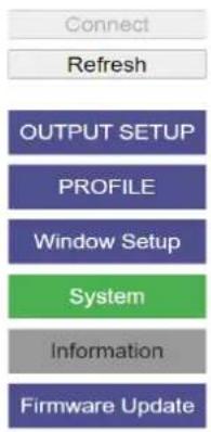
7.5. SYSTEM: allows user to reset the system and system DATA Backup/Restore in PC.
flowchart
graph TD
    A["Connect"] --> B["Refresh"]
    B --> C["OUTPUT SETUP"]
    C --> D["PROFILE"]
    D --> E["Window Setup"]
    E --> F["System"]
    F --> G["Information"]
    G --> H["Firmware Update"]
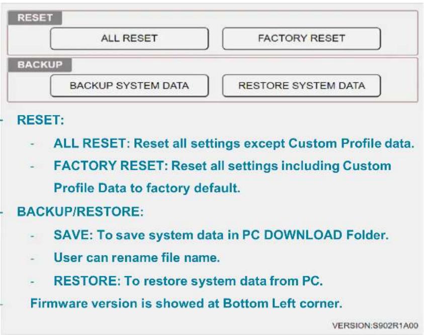
PS. WebUI doesn't support BACHUP and RESTORE functions at this moment.
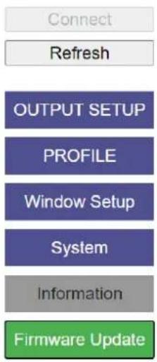
7.6. Firmware Update: allows user to update the FW through SCT but not WebUI..
flowchart
graph TD
    A["Connect"] --> B["Refresh"]
    B --> C["OUTPUT SETUP"]
    C --> D["PROFILE"]
    D --> E["Window Setup"]
    E --> F["System"]
    F --> G["Information"]
    G --> H["Firmware Update"]
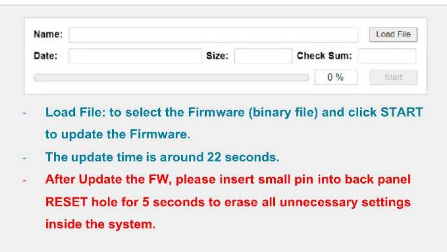
PS. WebUI doesn't support Firmware Update function at this moment.
8. Call for technical support
User can send e-mail to support@vigillink.com together with as much information as possible.
The following information is required for a swift response.
- Sink device (monitor): type and model number
- Monitor layout or specific application details
- GeoBox model No. and series No (On back label)
- Detailed timing of signal source and resolution.
- Press [Info] key to get System Information and send the data to us, including input/output timing and F/W version.
- The exact nature of the problem. Please be as detailed as possible.
- If possible, please attach the Pictures of the issue.
Usually, we will response with 24 hours (working day)
Please note that if the machine is sent back for repair, user needs to pay for return delivery cost.
9. Safety Precaution and Maintenance
Power Supply
Please connect electric power for all devices in the system from the same Power Distribution Box with correct grounding. Open the power after finishing system connection to reduce the risk for system damage from high floating voltage.
Working Environment
Please locate S902 in an environment free from dust, moisture and high temperature with good ventilation.
Maintenance and Repair
Apart from what is detailed in User Guide, maintenance should be carried out by competent technician assigned by VIGILLINK. If S902 is physically damaged, it should be returned for repair using VIGILLINK RMA procedures. If the unit is opened by user, it will lose the right for warranty protection.
10. Warranty and RMA policy
10.1. Warranty
This device is designed and tested to the highest standards and backed by two years' parts and labor warranty. Warranties are effective upon the first delivery date to the end customer and are non-transferable. Warranty period extension is available up to 5 years through paying extra charges.
10.2. RMA Policy
Return Material Authorization (RMA)
In the event that a product needs to be returned for repair, inform manufacturer and ask for a Return Material Authorization number.
RMA procedures:
- Prior to returning any item, user must receive a Return Material Authorization (RMA) number.
- All RMA numbers must appear on the return-shipping label.
- All RMA numbers are valid for ten (10) days from the issue date.
- All shipping and insurance charges in all RMAs must be prepaid by the customer.
Shipping charges and repair fees
- Within warranty period: The customer shall pay shipping charges when the unit is returned for repair. Manufacturer will pay shipping charges for return shipment to customer. All the inspection, material and repairs fees shall be borne by manufacturer.
-
Outside warranty period:
-
User shall pay for the inspection, material and labor cost for the repairs and pay for all shipping freight and insurance cost.
- Manufacture shall give quotation to user and user can make decision whether this repair shall be executed or not. If user decides to return the unit, user shall pay for the return cost.
Specifications
Input ports: 4x HDMI 2.0. Max. input resolution: 4096*2160 @60Hz.
Supports interleaved and progressive input signals with 4:2:0/4:2:2/4:4:4, 8/10-bit color.
✿ Supports CEA standard video timings with high end scaling up and down up to 600 MHz.
- Two simultaneous HDMI 2.0 output displays with the same output resolution, shared the same signal sources and display Windows.
Each Window can select one input signal from any input port. The same signal source can be assigned to the two different windows.
Each output display shows up to 4 Windows with flexible window location, resizing, scaling, positioning, cropping and color correction. PIP/POP and Overlapping are included.
User can set Overlap priority in each output port separately.
If two output ports select the same display Windows, it will show the same Window setup. If select different Windows, user can adjust Window setup independently.
Support 16 Transition effects including Seamless, Fade-in, Fade-out, Dissolve and Wipe. Only Fade-in/Out is functional in multiple Windows mode switching.
✨ Seamless switching in source selection and display mode switching.
Output signal: Progressive full color RGB 4:4:4.
✨ HDCP: V2.2/V1.4 compliant.
Support xvYCC 8/10/12-bit wide color gamut input signal processing.
1-2 frame latency based on different application: 16.7ms-33.3ms (V=60Hz)
* Preset 14 output timings and 12 EDID from XGA to 3840*2400 @60 for each input port.
✨ Selectable OSD transparency and turn-off time.
✨ Image freeze, flip and upside down.
✨ Box ID for multiple boxed individual control.
Standby mode to allow user cuts off output signal when no input signal is detected.
◇ Control: Front panel keypad, IR remote controller, RS232, USB control tool, Ethernet, WebUI.
12 system presets and 20 custom Profile presets. The preset includes transition effect.
✨ Selectable high end video processing: 3:2/2:2 cadence, diagonal correction and noise reduction.
High quality scaling engine for image scaling up and down in the range from XGA to 4k/2k.
3D motion adaptive de-interlace for interlaced input.
Embedded HDMI audio, SPDIF digital and analog R/L 3.5mm Jack audio outputs. Each audio output can select independent audio source from the inputs.
✿ ESD Protection: ±15kV (Air-gap discharge), ±8kV (Contact discharge)
DC power supply: DC adapter: 12V 2A (100V-240V), max. Power consumption: 22.5W, standby: 1.9W
Working environment: 40° C, 10-90% RH
Dimensions (Body only): 440mm*160mm*41mm (without protruding parts).
✨ Weight: 2.4kg (body only)
CE/FCC/RoHS Certified
2 Year Warranty, extension package is available up to 5 years.
Prospect functions in the future
✨ UDP control through Ethernet.
✨ Chromakey function.
✨ Programmable background with customized picture and logo.
Disclaimer/Copyright Statement
Copyright 2024, VNS Inc. All Right Reserved
This information contained in this document is protected by copyright. All rights are reserved by VNS Inc. VNS Inc. reserves the right to modify this document without any obligation to notify any person or entity of such revision. Copying, duplicating, selling, or otherwise distributing any part of this document without signing a non-disclosure agreement with an authorized representative of VNS Inc. is prohibited. VNS Inc. makes no warranty for the use of its products and bears no responsibility for any error of omission that may appear in this document.
Product names mentioned herein are used for identification purposes only and may be trademarks of their respective companies.
Limited Warranty and RMA statement
This device is designed and tested to the highest standards and backed by two years' parts and labor warranty. Warranties are effective upon the first delivery date to the end customer and are non-transferable. Warranty related repairs include parts and labor, but do not include repair of faults resulting from user negligence, special modifications, abuse (mechanical damage), shipping damage, and/or other unusual damages. The customer shall pay shipping charges when the unit is returned for repair. Manufacturer will pay shipping charges for return shipments to customers.
Manufacturer does not assume responsibility for consequential damages, expenses or loss of revenue, inconvenience or interruption in operation experienced by the customer. Warranty service shall not automatically extend the warranty period.
User can pay extension fee to extend the warranty period. Please contact us for more details. In the event that a product needs to be returned for repair, inform manufacturer and ask for a Return Material Authorization number.
FCC/CE statement
This equipment has been tested and found to comply with the limits for a Class A digital device, pursuant to part 15 of the FCC Rules. These limits are designed to provide reasonable protection against harmful interference when the equipment is operated in a residential / commercial environment. This equipment generates, uses, and can radiate radio frequency energy and, if not installed and used in accordance with the instruction manual, may cause harmful interference to radio communications. Operation of this equipment in a residential area is likely to cause harmful interference in which case the user will be required to correct the interference at his own expense.
Revision History
| Revision | Date | Originator | Comments |
| V1.00 | 2024-0305 | Steve Wang | First version |
| V1.01 | 2024-0315 | Steve Wang | Add WebUI user guide |
| V1.02 | 2024-0322 | Steve Wang | Content update |