M801 - Processor GeoBox - Free user manual and instructions
Find the device manual for free M801 GeoBox in PDF.


User questions about M801 GeoBox
0 question about this device. Answer the ones you know or ask your own.
Ask a new question about this device
Download the instructions for your Processor in PDF format for free! Find your manual M801 - GeoBox and take your electronic device back in hand. On this page are published all the documents necessary for the use of your device. M801 by GeoBox.
USER MANUAL M801 GeoBox
The absolute opposite of ordinary
M800 Edge Blending processor User Guide
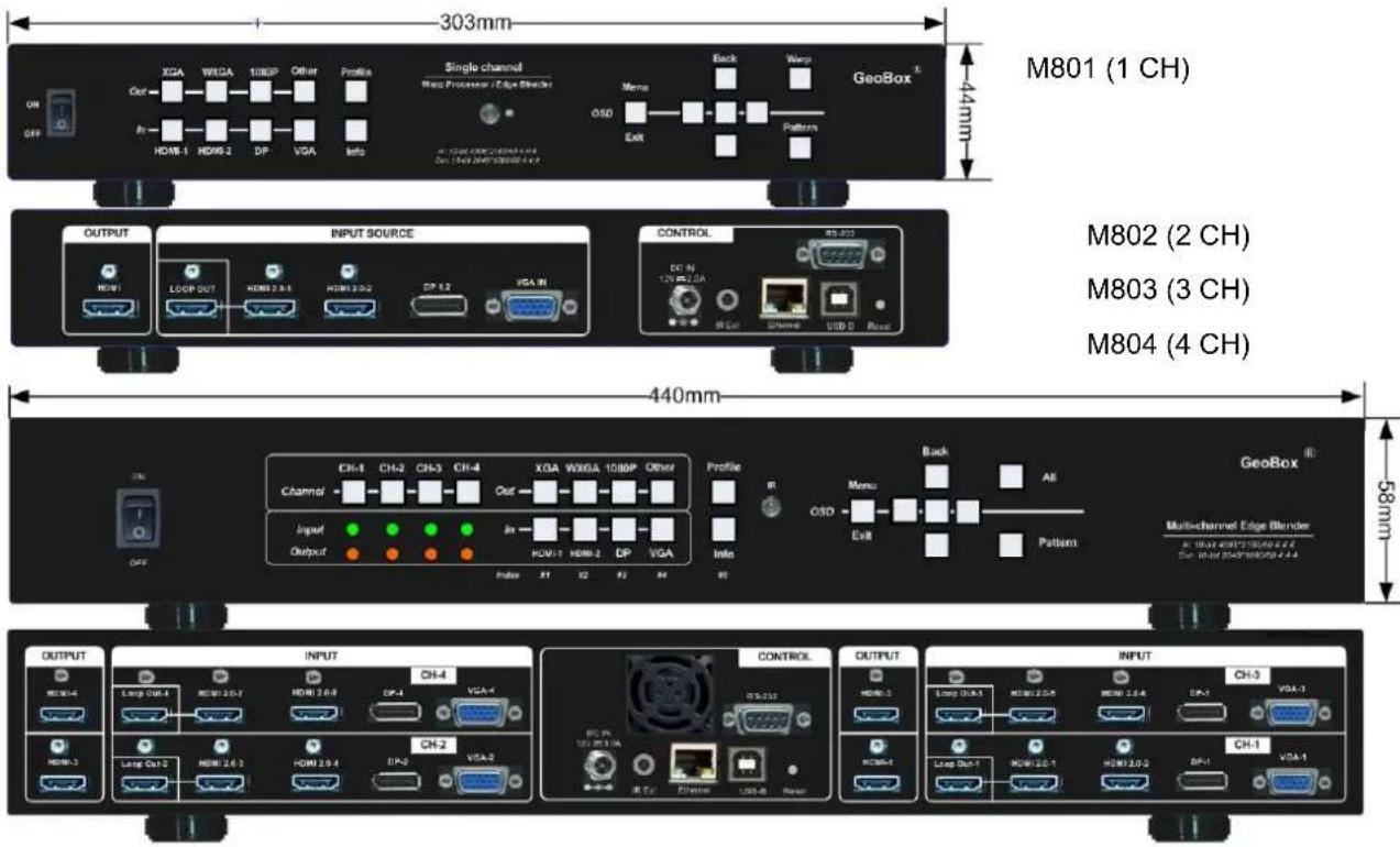
M801 (1 CH), M802 (2 CH), M803 (3 CH), M804 (4 CH)
Input: up to 4096*2160 @60Hz 4:4:4 full color sampling
Output: 2048*1080 @60Hz
New generation Warp & Edge blending engine
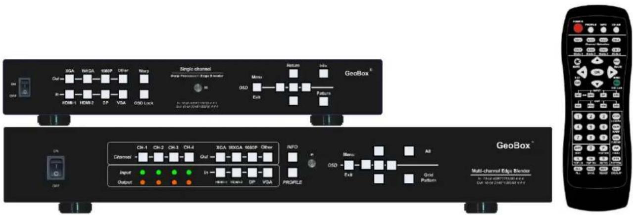
text_image
Single channel Warp Promote/Edge Blender GeoBox® CH-1 CH-2 CH-3 CH-4 XGA WXDA 1660P Other Channel → → → → Out → → → Input ● ● ● In → — — — — — Output ● ● ● ● → → → → → → → Grid Pattern Profile Menu Ex8 Grid Pattern CH-1 CH-2 CH-3 CH-4 XGA WXDA 1660P Other GeoBox™ Multi-channel Edge Blender DUR: 10.05 (200V) (10.05 V) GEO BoxTable of Contents
Disclaimer/Copyright Statement.... 3
Warranty/RMA.... 3
FCC/CE Statement.... 3
Introduction.... 4
Specification.... 6
Functions and Features.... 7
-
Content in the packing box.... 10
-
Basic operation & settings.... 10
2.1. Connecting the Inputs.... 10
2.2. Connecting the Outputs.... 10
2.3. Input / Output Selection & LED indicators.... 11
2.4. System Connection and Power On.... 13
2.5. HDMI Loop Out for daisy chain connection.... 14
2.6. System Settings: Box ID, RS232, Ethernet.... 14
2.7. How to use IR Remote Controller.... 16
2.8.Full screen and native aspect ratio....17
2.9. Image rotation and flip.... 17
2.10. Global Color adjustment.... 18
2.11. OSD Lock and unlock.... 19
2.12. System synchronization.... 19
2.13. Dual window display—PIP/POP (Picture in picture & side by side) 20
2.14. Image Orientation (Flip & Rotation) 22
- Project plan and preparation for edge blending.... 23
3.1. Determine source signal resolution.... 23
3.2. Determine overlap region size and pixels.... 23
3.3. Relation between Overlap pixels and geometry alignment accuracy.... 24
3.4. Get installation data from VNS Excel Spread Sheet 25
3.5. Apply Spread Sheet data for projector installation and GeoBox setting.... 27
3.6. Projector settings before edge blending.... 28
3.7. GeoBox settings before edge blending.... 29
- Geometry Alignment.... 29
4.1. Select the right Grid Pattern for geometry alignment.... 29
4.2. Grid pattern pixel size selection.... 30
4.3. Geometry alignment.... 31
4.3.1. Geometry alignment through remote controller.... 32
4.3.2.Activate grid pattern.... 32
4.3.3.[2x2] 4 corner geometry alignment.... 32
4.3.4.[3x3], [5x3], [9x5] warp alignment.... 33
4.3.5.Linearity grid line adjustment.... 35
4.3.6.Corner [Wall] geometry adjustment.... 36
4.3.7. [Gwarp3] PC Tool 38
- [Video Wall] settings.... 39
5.1. [Zoom]: split the signal source.... 40
5.2. [Pan]: assign image location.... 40
5.3. [Overlap]: crop the right image for each projector.... 41
5.4. [Position]: shift image position without changing image size.... 41
6. [Edge Blend] settings.... 41
6.1. [Edge] selection location and set edge blending value.... 42
6.2. [Shift]: shift image position and execute Edge Mask.... 43
6.3. [Gamma]: color correction in edge blending area.... 43
6.4. Black level uplift: [Offset] & [Corner] adjustment.... 45
6.5. [Color]: Individual projector white balance and color correction.... 47
6.6. Edge [Mask]...... 48
6.7. [Grid] (More details in Section 4.2) 50
6.8. Final image quality fine-tuning.... 50
7. Example for 3 projector edge blending procedures.... 51
7.1. Get detailed edge blending information through VNS Excel Spread Sheet.... 51
7.2. Mark image location and install the projectors.... 52
7.3. System connection.... 52
7.4. Projector settings.... 53
7.5. GeoBox settings.... 53
7.6. Geometry alignment.... 54
7.7. Video wall settings.... 56
7.8. Edge blending setting.... 57
7.9. Final image quality fine-tuning.... 58
8. Save/Load system settings.... 58
9. Multiple unit applications.... 59
9.1. System connection in multiple unit edge blending.... 59
9.2. Content overlap setting issue 61
9.3. Convenient setting in multiple unit application.... 63
9.3.1. Setup by remote controller.... 63
9.3.2. Setup by Ethernet.... 63
10. WebGui and Gwarp3 PC tool.... 64
10.1.WebGui 64
10.2. Gwarp3 PC Tool 65
11. Advanced applications and settings.... 65
11.1. Immersive display with multiple projectors.... 65
11.2. Portrait edge blending.... 67
11.3. Flexible display.... 68
11.4. Discrete content displayed in each projector.... 69
11.5. Complete system aspect ratio adjustment.... 70
12. Miscellaneous settings.... 71
12.1. Helpful tips for edge blending.... 71
12.2. EDID settings.... 72
12.3. HDMI vs. DVI output signal.... 73
12.4. System standby and automatically turn off output signal.... 73
12.5. Change background color.... 73
12.6. Turn off Splash screen Logo.... 74
12.7. Limitation in audio output.... 74
- Trouble shooting.... 74
13.1. Front panel LED indicators.... 74.
13.2. Intermittent or loss of input signal.... 74
13.3. Video quality issues.... 75
13.4. Image position shift after installation.... 75
13.5. System crash and malfunction 76
13.6. Synchronization issue in the outputs.... 76
- Technical support.... 77
- Safety precaution and maintenance.... 77
Specification 79
Revision History....80
Disclaimer/Copyright Statement
Copyright 2018, VNS Inc. All Right Reserved
This information contained in this document is protected by copyright. All rights are reserved by VNS Inc.
VNS Inc. reserves the right to modify this document without any obligation to notify any person or entity of such revision. Copying, duplicating, selling, or otherwise distributing any part of this document without signing a non-disclosure agreement with an authorized representative of VNS Inc. is prohibited. VNS Inc. makes no warranty for the use of its products and bears no responsibility for any error of omission that may appear in this document.
Product names mentioned herein are used for identification purposes only and may be trademarks of their respective companies.
Limited Warranty and RMA statement
This device is designed and tested to the highest standards and backed by two years' parts and labor warranty. Warranties are effective upon the first delivery date to the end customer and are non-transferable. Warranty related repairs include parts and labor, but do not include repair of faults resulting from user negligence, special modifications, abuse (mechanical damage), shipping damage, and/or other unusual damages. The customer shall pay shipping charges when the unit is returned for repair. Manufacturer will pay shipping charges for return shipments to customers.
Manufacturer does not assume responsibility for consequential damages, expenses or loss of revenue, inconvenience or interruption in operation experienced by the customer. Warranty service shall not automatically extend the warranty period.
User can pay extension fee to extend the warranty period. Please contact us for more details. In the event that a product needs to be returned for repair, inform manufacturer and ask for a Return Material Authorization number.
FCC/CE statement
Note: This equipment has been tested and found to comply with the limits for a Class A digital device, pursuant to Part 15 of FCC Rules. These limits are designed to provide reasonable protection against harmful interference in a residential installation. This equipment generates, uses and can radiate radio frequency energy and, if not installed and used in accordance with the instruction, may cause harmful interference to radio communications. However, there is no guarantee that interference will not occur in a particular installation. If this equipment does cause harmful interference to radio or television reception, which can be determined by turning the equipment off and on, the user is encouraged to try to correct the interference by one or more of the following measures:
- Reorient or relocate the receiving antenna.
- Increase the separation between the equipment and receiver.
- Connect the equipment into an outlet on a circuit different from that to which the receiver is connected.
- Consult the dealer or an experienced radio/TV technician for help.
Notice:
(1) An Unshielded-type power cord is required in order to meet FCC emission limits and also to prevent interference to the nearby radio and television reception. It is essential that only the supplied power cord by used.
(2) Use only shielded cables to connect I/O devices to this equipment.
(3) Changes or modifications not expressly approved by the party responsible for compliance could void the user's authority to operate the equipment.
Introduction
M800 is curved screen edge blending processor with the ability to provide multiple processing modules to control from 1 to 4 projectors based on user's requirements. M801 is designed with one processing module to control one projector, M802 for 2 projectors, M803 for 3 projectors and M804 for 4 projectors. It was designed for sophisticated edge blending as well as image warping, stacking and projection mapping...etc. One M804 can execute 4 projector edge blending without any additional equipment or splitter. Two M804 can control up to 8 projectors. More M800 can be cascaded for large scale display.
4 input ports (2x HDMI, 1x DP, 1x VGA) and 1x HDMI outputs are designed in each processing module. Digital input supports up to 4096*2160 @60Hz with 4:4:4 full color sampling. Output supports up to 2048*1080 @60Hz. It is integrated with 10-bit high end processor, motion adaptive de-interlace, low angle smooth algorithm, 3:2/2:2 pull-down and supports non-VESA standard input timing. Programmable EDID can optimize input timing to get the best video result.
Advanced warp technology is embedded in M800. User can use IR controller, USB, Web Gui and Ethernet to perform edge blending and sophisticated geometry alignment up to 17x17 control points. Linearity Grid Line Adjustment and Corner Wall image adjustment for mapping image at 90 degrees corner is a new function in geometry alignment. Separate R, G, B gamma correction for edge blending region color fine-tune, individual global color correction for each output, fine pixel color uniformity and 9 regions non-edge blending area black level uplift are also standard functions in M800. Users can see real time geometry and color adjustment to get optimized result.
Image 90/180/270 degrees rotation and flip with 4k/60 input from various input sources are embedded in M800. It provides more flexible system configuration ability.
HDMI loop out supports daisy chain connection up to 4096x2160 @60Hz and allows large display with multiple M800 cascaded. Video wall function in M800 is to crop and allocate source image for each projector and set overlap pixels for edge blending. Complete curved edge blending can be achieved through remote controller and Ethernet without PC software, video distributor and splitter.
PIP (picture in picture) and POP (side by side) are standard functions in M800. PIP image size is from 320*180 up to 1920*1200. In one M804, user can display up to 8 different input contents on the screen.
M800 is an ideal solution for simulation. It can connect with inputs from multiple PCs and combine them into one seamless image. It also provides flexible displays in edge blending system. For a 3x projector edge blending system, user can configure as 1+1+1 independent display, 1+2 (two projectors blended) and all-in-one (three projectors blended). User can also execute edge blending with projector at portrait position without rotating source image to increase image height. It is a good fit with laser projector without the limitation in installation angle.
Using M800, users can replace high end projector with low cost projector without lens shift, warp and edge blending. It provides easy configuration, low entry barrier, cost effective, reliable and flexible solution.
text_image
303mm 44mm M801 (1 CH) OUTPUT INPUT SOURCE CONTROL M802 (2 CH) M803 (3 CH) M804 (4 CH) 440mm 58mm OUTPUT INPUT CONTROL M803 (Multi-channel Edge Blender) OUTPUT INPUT CONTROL M804 (4 CH)(The back panel shows 4 CH model—M804)
text_image
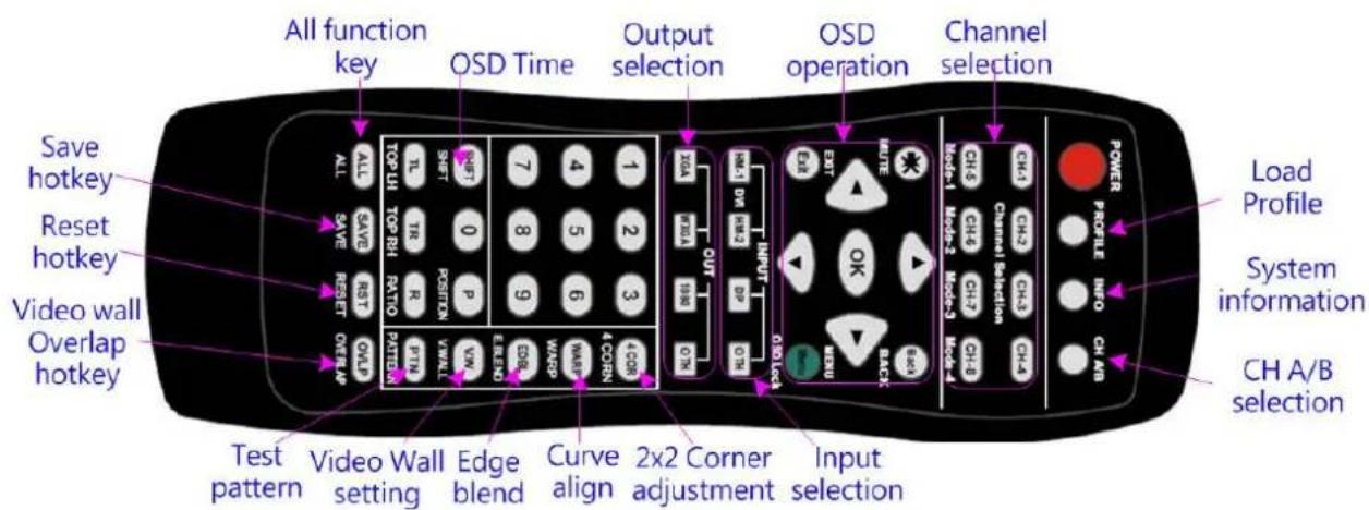
All function key OSD Time Output selection OSD operation Channel selection Save hotkey Reset hotkey Video wall Overlap hotkey ALL SAVE RESET OVER AP SETTEN PATTEN VWALL SHIFT 0 Position P OUT R R10 TR R11 R12 R13 R14 R15 R16 R17 R18 R19 R20 R21 R22 R23 R24 R25 R26 R27 R28 R29 R30 R31 R32 R33 R34 R35 R36 R37 R38 R39 R40 R41 R42 R43 R44 R45 R46 R47 R48 R49 R50 R51 R52 R53 R54 R55 R56 R57 R58 R59 R60 R61 R62 R63 R64 R65 R66 R67 R68 R69 R70 R71 R72 R73 R74 R75 R76 R77 R78 R79 R80 R81 R82 R83 R84 R85 R86 R87 R88 R89 R90 R91 R92 R93 R94 R95 R96 R97 R98 R99 Power Profile INFO CH A/B Channel Selection CHA Channel Selection CHA Channel Selection CHA Channel Selection CHA Channel Selection CHA Channel Selection CHA Channel Selection CHA Channel Selection CHA Channel Selection CHA Channel Selection CHA Channel Selection CHA Channel Selection CHA Channel Selection CHA Channel Selection CHA Channel Selection CHA Channel Selection CHA Channel Selection CHA Channel Selection CHA Channel Selection CHA Channel Selection CHA Channel Selection CHA Channel Selection CHA Channel Selection CHA Channel Selection CHA Channel Selection CHA Channel Selection CHa Channel Selection CHa Channel Selection CHa Channel Selection CHa Channel Selection CHa Channel Selection CHa Channel Selection CHa Channel Selection CHa Channel Selection CHa Channel Selection CHa Channel Selection CHa Channel Selection CHa Channel Selection CHa Channel Selection CHa Channel Selection CHa Channel Selection CHa Channel Selection CHa Channel Selection CHa Channel Selection CHa Channel Selection CHa Channel Selection CHa Channel Selection CHa Channel Selection CHa Channel Selection CHa Channel Selection CHa Channel Selection CHA Channel Selection CHa Channel Selection CHa Channel Selection CHa Channel Selection CHa Channel Selection CHa Channel Selection CHa Channel Selection CHa Channel Selection CHa Channel Selection CHa Channel Selection CHa Channel Selection CHa Channel Selection CHa Channel Selection CHa Channel Selection CHa Channel Selection CHa Channel Selection CHa Channel Selection CHa Channel Selection CHa Channel Selection CHa Channel Selection CHa Channel Selection CHa Channel Selection CHa Channel Selection CHa Channel Selection CHA Channel Selection CHA Channel Selection CHA Channel Selection CHA Channel Selection CHA Channel Selection CHA Channel Selection CHA Channel Selection CHA Channel Selection CHA Channel Selection CHA Channel SelectionCHA Channel SelectionCHA Channel SelectionCHA Channel SelectionCHA Channel SelectionCHA Channel SelectionCHA Channel SelectionCHA Channel SelectionCHA Channel SelectionCHA Channel SelectionCHA Channel SelectionCHA Channel SelectionCHA Channel SelectionCHA Channel SelectionCHA Channel SelectionCHA Channel SelectionCHA Channel SelectionCHA Channel SelectionCHA Channel SelectionCHA Channel SelectionCHA Channel SelectionCHA Channel SelectionCHA Channel SelectionCHA Channel SelectionCHA Channel SelectionCHA Channel SelectionC H A/B selectionSpecification
✧ Each box has 1-4 processing modules.
- M801: Single module processor
- M802: Dual module processor
- M803: Triple module processor
- M804: Quad module processor
◆ Each processing module includes:
- Input: 2x HDMI 2.0b, 1x DP1.2a and 1x VGA
- Output: 1x HDMI
- Loop output: 1x HDMI 2.0 for cascade.
◇ HDCP: HDMI V2.2/V1.4, DP: HDCP: V1.3
Max. input resolution: 4096x2160 60fps
Output: HDMI up to 2048x1080/60, output signal is RGB 4:4:4 progressive.
✿ New generation warp engine for geometry alignment up to 17x17 grid control points.
Maximum geometry adjustment up to 1200 pixels in both H&V directions.
Edge blending at 4 edges up to H=1920 pixels, V=1200 pixels with independent R, G, B gamma correction.
✿ 9 regions black level uplift to compensate light leakage from projector optical system.
✿ Support Corner Wall adjustment in H&V at flexible location.
✿ Support Linearity Grid Line adjustment for quick H&V line position alignment.
✿ Embedded video wall function for image split, cropping and edge blend overlap pixel setting.
✿ Support non-VESA standard input timings for easy connection with various signal sources.
✧ Selectable output up to 2048*1080 60Hz.
Selectable grid pattern size from 8-120 pixels in H&V direction. Default is 32^*32 pixels.
✧ Selectable grid pattern color with optional transparency to see background image.
✿ Flexible aspect ratio adjustment in each edge up to +_ 1800 pixels position shift.
◇ Frame lock function to get perfect synchronized outputs in all channels.
◇ Frame rate conversion and 50Hz in/out function to eliminate image frame repeat.
- Three synchronization method: phase lock, frame lock & free-run modes.
✿ Free-run mode provides continuous signal to projector, no source searching required when timing change.
✿ 10-bit processor, 3:2/2:2 cadence, low angle smooth algorithm, high quality scaling engine.
✿ 4:4:4 Chroma sampling, 30 Color bits, 12-bit RGB gamma CLUT.
✿ Support sRGB & xvYCC color processing & 8/10/12-bit deep color.
✿ 3D motion adaptive de-interlace.
High Dynamic Range (HDR) support: SMPTE ST-2084, SMPTE ST-2086
❖ Individual color and white balance adjustment in each processing channel. - Individual 90/180/270 rotation, flip, cropping, scaling & color adjustment in each channel up to 4k/60 input.
✿ PIP/POP function with PIP image size from 320*180 up to 1920*1200 resolution with flexible position and selectable aspect ratio. This function is not available when the main image is 90/270 degrees rotation.
✨ Embedded HDMI audio outputs.
✨ Selectable and programmable EDID.
✿ ESD Protection: ±8kV (Air-gap discharge), ±4kV (Contact discharge)
Power supply: AC In: 100V-240V, DC Out: 12V 3A
Max. Power consumption: max. 28w (M804)
✨ Working environment: 45° C, 10-90% RH
◇ Control: keypads, IR, RS232, USB, Ethernet
✨ System settings can be stored and backup.
◇ Dimensions: M801: 303mm*180mm*45mm, weight: 1.8kg M802-M804: 440mm*180mm*55mm Weight: 2.4kg-2.8kg
CE/FCC/RoHS/Reach Certified
✿ 2 Year Warranty, paid extension available up to 5 years.
Function and features:
A. Structure
Each M800 consists of 1-4 processing modules. Each processing module can control one projector and multiple processing modules can be cascaded to control big scale display system.
B. Each processing module includes below input and output ports
-
Input: 2x HDMI, 1x VGA, 1x DisplayPort °
-
HDMI & DisplayPort support 4096*2160 @60Hz, 3840*2400 @60Hz with 4:4:4 chroma sampling without compression. VGA supports up to WUXGA or 205MHz analog input signal.
-
Connect with various video sources and support none VESA standard input resolution up to 120Hz.
-
Output: 1x HDMI. Selectable output resolutions: 720x480、XGA、WXGA、1280x1024、1366x768、1400x1050、1600x1200、1920x1080 (24/30/50/60Hz)、1920*1200/60、2048x1080/60。All output are RGB 4:4:4 progressive signals.
-
Loop out port: 1x HDMI, same as source signal up to 4096*2160@60Hz & 3840x2400@60Hz.
C. Image warp, geometry alignment and edge blending
-
Selectable grid pattern size for geometry alignment from 8-120 pixels in H&V. Default is 32*32 pixels.
-
With full functions for quick 4 corner alignment, vertical and horizontal keystone correction, Pincushion & Barrel adjustment, image warp and image 90/180/270 degrees rotation and flip.
-
Each module controls one projector and can be cascaded to control unlimited number of projectors.
-
Integrated with full function front panel keypads & IR remote controller for manual geometry alignment through OSD up to 9*5 grid patterns with +_1200 pixels adjustment range at each corner. 3x3 edge center geometry alignment range is limited to +_600 pixels in full HD output in top edge and both side edges. Bottom edge is limited to 300 pixels. In most of curved screen edge blending system, the projector will be installed at ceiling position, the lower position of the image has more distortion and will be at top edge of GeoBox. It can match +_600 pixels adjustment range without problem.
-
Gwarp3 PC tool is available for warp and geometry alignment up to 17x17 grid patterns through USB or Ethernet. The geometry alignment range is the same as manual adjustment. After finishing geometry alignment, the parameters will be stored inside GeoBox and no more PC tool is needed.
-
Corner wall geometry alignment at 90 degrees corner wall up to 900 pixels adjustment range in H&V directions. The adjustment point can be changed up to 900 pixels in H&V directions.
-
4 directions edge blending up to H=1920, V=1200 overlapped pixels for flat, dual curved & cylindrical screens.
-
Independent R, G, B gamma correction for edge blending color fine.
-
Precise black level uplift at multiple areas (up to 9) to compensate light leakage in the projector optical system in dark environment.
-
White balance and individual color correction for each projector.
D. High end 10-bit video processor
- 10-bit high end processor with 3D motion adaptive de-interlace, low angle smooth algorithm and 3:2/2:2 film mode detect and recovery function.
- Complete color adjustment function, including brightness, contrast, hue, saturation, preset color mode, independent RGB color adjustment and white balance correction.
E. Edge mask
Image [Shift] to execute edge mask up to 500 pixels following the image profile after geometry adjustment and [Edge Mask] with 8 adjustment points to provide irregular shape edge mask with random edge position up to 900 pixels in each control point. These two functions can be executed at the same time.
F. PIP/POP
- PIP (picture in picture): with flexible PIP size (320*180 to 1920*1080), location and aspect ratio.
- POP (Picture outside picture): side by side images with full screen or maintain original aspect ratio.
- PIP/POP can only be displayed within one projector. If user wants to implement this function across entire display screen, user need to set one processing module at the front end to implement PIP/POP function and connect the output as signal source to other processing modules to do edge blending.
- PIP/POP can support up to 4k/60 input but is not available when the main image is 90/270 degrees rotation. For image up/down flip, the function is still available.
G. Video wall function
- Image cropping and location assignment for each projector.
- Image pixel cropping range is up to 1800 pixels for image position shift, aspect ratio adjustment, bezel compensation and creating overlap region for edge blending.
- Connect with 4k/2k input signal and split the image for display devices without additional PC, image splitter or other devices.
- Serve as video wall controller for irregular video wall display up to 15x15 matrix display from single signal source.
H. Image rotation and flip
- Image 90/180/270 degrees rotation, flip and mirror up to 4k/60Hz input resolution.
- Image flip in Front/Rear, Left/Right and Top/Bottom directions.
- When execute PIP/POP function, no 90/270 degrees image rotation is available.
- No 3D motion adaptive de-interlace function while the image is 90/270 degrees rotated. We propose to apply progressive signal source to get the best video quality.
I. Color uniformity adjustment
Details for color uniformity adjustment will be determined later.
J. System control and other features
- Professional design and reliable for 7/24 working condition.
- 1.3U housing for easy rack installation.
- Operation temperature: 0-45 °C. Relative humidity: 10%-90% non-condensing.
- Replace high price projector with low cost projector and achieve the same functionality.
- Full function OSD by front panel keypad, Web Gui & IR remote controller.
- Full function system setup through front panel keypads, remote controller, USB, WebGui or Ethernet (Including through WiFi by PC, Mobile or iPad).
- Firmware update via USB or Ethernet.
- Gwarp3 PC tool can control multiple processors simultaneously through USB or Ethernet.
- Internal grid pattern with selective color for easy geometry alignment.
- RS232 & Ethernet system control compatible with most of control system.
- User can select blue or black background color when no input signal is detected.
- Programmable EDID in the range at H=1024\~3840, V=720\~2400.
- BOX ID and programmable IP address for convenient multiple units control at the same time.
- User can save up to 5 settings and can be recalled by remote controller, RS232, USB or network.
- System settings can be backup in PC, USB device and copied to another unit.
- Automatic power ON/OFF through input signal control. While no input signal is detected, it will shut down output automatically. User can power ON/OFF the system through the control in signal source.
1. Content in the packing box
The M800 Quad Channel Video Wall Controller
✦ 1x RC-400 IR Remote Controller with two AAA battery
✦ 1x IR Extending Receiver with 1.8m cable
1x DC Power supply unit with power cord, In: AC 100V-240V, Out: DC 12V 3A
✨ Mounting bracket with screw (Option)
Please download User Guide & Gwarp3 PC Tool at www.vnstw.com.
2. Basic operation & setting
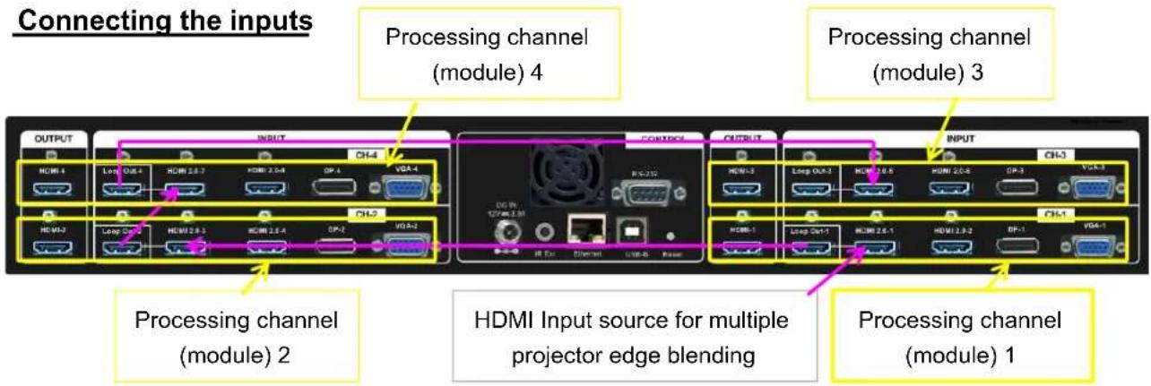
2.1. Connecting the inputs
text_image
Connecting the inputs Processing channel (module) 4 Processing channel (module) 3 OUTPUT INPUT CH-4 HDMI 1 Loop OUT 4 HDMI 2.0-7 HDMI 2.0-4 DP-4 VGA-4 HDMI 2 Loop OUT 5 HDMI 2.0-3 HDMI 2.0-4 DP-2 VGA-2 CONTROL R/C:252 Output INPUT HDMI 3 Loop OUT 3 HDMI 2.0-6 HDMI 2.0-4 DP-3 VGA-3 HDMI 1 Loop OUT 1 HDMI 2.0-1 HDMI 2.0-2 DP-1 VGA-1 Processing channel (module) 2 HDMI Input source for multiple projector edge blending Processing channel (module) 1Each processing channel (module) has four input ports: 2x HDMI, 1x DP, 1x VGA
HDMI & DP input ports support up to 4096x2160 @60 Hz.
Only HDMI-1, HDMI-3, HDMI-5 & HDMI-7 input signals can be looped out. Loop out signal is unprocessed source signal.
For edge blending application, user can connect signal source to any of above HDMI input port and loop out to the second processing module HDMI input port. All processing channels (modules) shall be fed with the same signal. No specific connection sequence is required.
2.2. Connecting the outputs
text_image
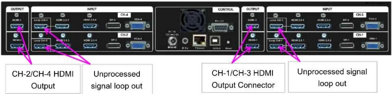
OUTPUT HCMI-4 Loop Out-4 HDMI 2.0.7 HDMI 2.0.4 DP-4 VGA-4 HCMI-3 Loop Out-2 HDMI 2.0.3 HDMI 2.0.4 DP-2 VGA-2 CH-2/CH-4 HDMI Output Unprocessed signal loop out CONTROL BC-1A DC-1A 2.5A RR-232 R Ex Chimer USB-6 Power OUTPUT HCMI-3 Loop Out-3 HDMI 2.0.5 HDMI 2.0.4 DP-3 VGA-3 HCMI-3 Loop Out-1 HDMI 2.0.1 HDMI 2.0.2 DP-1 VGA-1 CH-1/CH-3 HDMI Output Connector Unprocessed signal loop outFor 4 projectors edge blending application, user can connect any output to any projector and select projector location via [Video Wall]→[Pan] menu.
If independent content display is required, user needs to arrange the input source and output connection and let input source be displayed at specific projector.
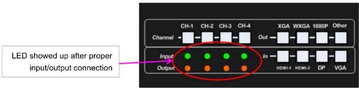
Once input signal and output ports are properly connected, LED indicator on the front panel will show up. If any of the LED in CH-1 \~ CH-4 is not lighted up, please check the input/output connection and cable.
text_image
LED showed up after proper input/output connection Channel CH-1 CH-2 CH-3 CH-4 XGA WXGA 1080P Other Input In HDMI-1 HDMI-2 DP VGA Output2.3. Input / Output selection & LED Indicators

text_image
Channel selection keypad Output resolution selection Keypad Channel CH-1 CH-2 CH-3 CH-4 XGA WXGA 1080P Other Output In HDMI-1 HDMI-2 DP VGA If projector is detected, the LED will light up If Input Source is detected, LED will light up Input port selection keypad Select CH, then select input port and output resolution. Press CH key to select operation channel.2.3.1. Input source selection
√ Default input port are HDMI-1/HDMI-3/HDMI-5/HDMI-7.
√ User can press CH key, then select different input port for each channel.
√ For one content edge blending display (all-in-one), user needs to input signal to HDMI-1 / HDMI-3 / HDMI-5 or HDMI-7, then loop out to next processing channel to let all channels be fed with the same signal source.
√ If multiple units of M800 are cascaded for edge blending, user needs to connect loop out of the last channel to next unit HDMI input port, then loop out to all channels in next unit.
√ If user wants to select two input sources for multiple unit cascade application, user needs to add one HDMI switcher or video distributor (or splitter) in signal source and feeds the same signal to all M800 processing channels.
√ User can select different input source for each channel to display separate content in each projector. Please see more details in flexible display section.
√ PIP/POP is integrated in each processing channel. However, only one HDMI input signal can be selected in each processing channel in PIP/POP application. Please see more details in PIP/POP section.
2.3.2. Output resolution selection
√ User needs to select output resolution in each processing channel separately. The output resolution selection will apply to single channel. Default output resolution is 1080p.
√ The output resolution should be the same as the projector native resolution. If user changes output resolution, geometry adjustment result will also be changed.
√ User can select output resolution through remote controller, USB or Ethernet.
√ Output resolution list: 720x480, XGA, WXGA, 1280x1024, 1366x768, 1400x1050, 1600x1200, 1920x1080 (24/30/50/60Hz), 2048x1080/60 & 1920*1200/60。All output default resolution is 60Hz, RGB 4:4:4 and progressive.
√ If the output refresh rate is not the same as input refresh rate. The frame lock function will be disabled and it may cause not synchronization issue among output channels. If the input is 4k/30 with FHD/60 output, it will have no synchronization problem. If the input is 50Hz, please select 1080p 50 Hz output to avoid frame repeat issue.
√ User can set EDID to let input source provide desired resolution. However, input resolution is controlled by signal source and may not output desired resolution. In this case, manual setting in signal source output resolution may be required.
√ M800 can support non-VESA standard input timing once signal source can provide, such as 4096x2160, 3200x2400...
√ When press [OTH] key to select output resolution in remote controller, the monitor will show the timing and take few seconds to finish the selection.
√ User can click [Info] key to get system information and input / output signal resolution.
2.3.3. LED indicators
√ LED indicators will show the input/output signal status.
√ Green LED will show up when the input signal is detected.
√ Orange LED will show up when the display device (projector) is connected.
√ If user presses Menu key for 5 seconds on the remote controller, GeoBox OSD menu will be locked and the Power LED will be flashing. To press another 5 seconds, it will unlock OSD menu.
√ If multiple units are used in the system, user can set different ID and use remote controller [85x] key to execute independent control. Press [851] following other OSD keys, the remote controller can only show Box ID #1 OSD and Power LED on front panel in other units will be flashing. User can disable OSD LOCK with [850] command via IR controller.
2.4. System connection and Power On
➢ Poor quality HDMI cable and signal source will affect the connection distance and may cause signal noise or show intermittent image.
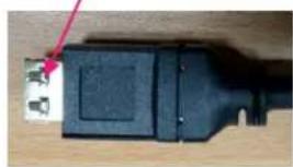
To ensure all cables are connected correctly, it is recommended to use locking cables. We can provide T-Lock cable with certified quality.
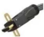
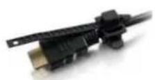
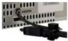
T-Lock cable
natural_image
Close-up of a black USB cable connector with a metallic connector and a red arrow pointing to it (no text or symbols visible)➢ Complete edge blending system should be connected to one power Distribution Box with proper grounding. Power on the system after finishing all connections to avoid system damage by floating voltage among devices.
When power is switched on, the booting time is about 19 seconds and the Input & Output LEDs on front panel will stay "Lighted" all the time for the channel with correct input source and output device connections.
If continuous flashing in power LED, it means the OSD function has been Locked. Please press [Menu] key for 5 seconds to disable [OSD Locked] function. If system lock is done by remote controller through [85x] operation, please press [850] to unlock system control.
2.5. HDMI Loop Out for daisy chain connection
text_image
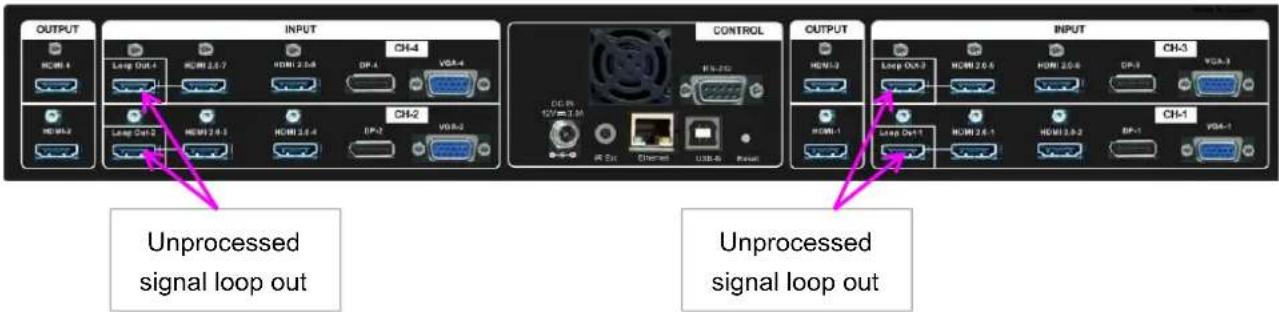
OUTPUT INPUT CONTROL OUTPUT INPUT Unprocessed signal loop out Unprocessed signal loop outHDMI Loop Out is for daisy chain connection. It is not an input port. Loop Out provides the same unprocessed source signal only from HDMI-1/HDMI-3/HDMI-5 or HDMI-7 input ports.
All the other input signals will not be looped out. If user wants to execute edge blending through other input signal, please add video distributor and feed signal to all channels.
User can connect any Loop Out signal to any HDMI input port in the following channel or GeoBox. No specific connection sequence is required. Once the signal can be fed to all channels, it will be OK.
User can connect up to more than 2-3 units of M804 through daisy chain connection. The daisy chain connection number is related to the quality of HDMI cables and signal source resolution—good cable or lower source resolution can connect more units. User can also add HDMI splitter at the front end to increase the connection number for large scale video display.
If loop out port is not connected, user can connect to a monitor for signal source monitoring purpose.
2.6. System settings: Box ID, RS232, Ethernet
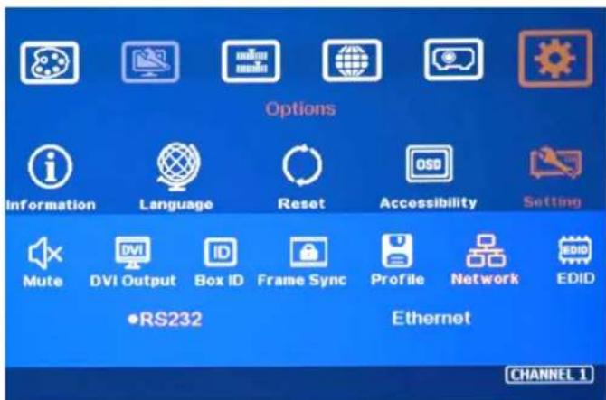
Box ID, RS232 and Ethernet settings can be executed through CH-1 or CH-2. The setting result will be applied to complete unit.
User can control or operate M800 settings through Ethernet. Default IP address is 192.168.0.100.
When multiple units are used at the same time, user can set different IP address in each M800 so that each M800 can be controlled independently.
2.6.1. Box ID
√ The range of Box ID is 0 \~ 99 for RS2323 command.
√ If user uses remote controller to execute system operation, the Box ID range is 0 \~ 9.
2.6.2. RS232 settings
text_image
Options Information Language Reset Accessibility Setting Mute DVI Output Box ID Frame Sync Profile Network EDID •RS232 Ethernet CHANNEL 1√ RS232 is designed with DB-9 connector. User can select baud rate between 11520 and 9600.
√ We can provide UART protocol for the control from RS-232 or Ethernet.
2.6.3. Ethernet
√ User needs to connect M800 to WiFi Router or switch/hub through RJ45 to LAN port. Then user can control the system through Ethernet.
√ Crossover UTP cable can be used for direct connection between PC and GeoBox. User needs to set PC TCP/IPv4 with the same domain segment as GeoBox (for instance, to set IP address at 192.168.0.105) and subnet mask at 255.255.255.0).
√ Open web browser (Google Chrome or Internet Explorer) and input M800 IP address (default is 192.168.0.100), user can see GeoBox WebGui and menu with virtual keys similar to OSD for further system operation. There is no additional software is required.
√ If user can't connect the network, please power off/on M800 again to let PC detect M800 network system.
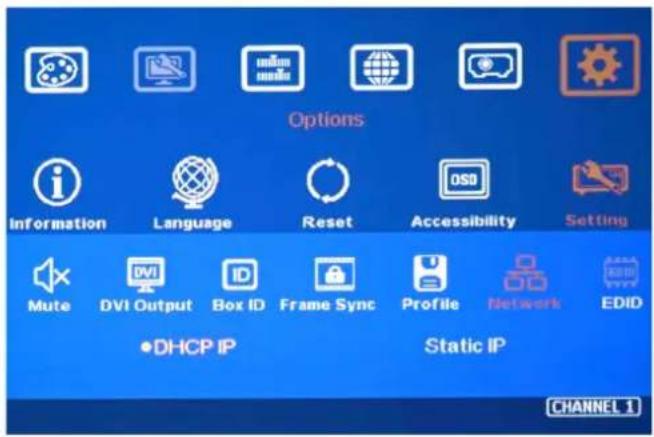
√ User can set DHCP for the connection. If necessary, please [Renew] DHCP to get IP address before network connection.
√ Gwarp3 PC Tool is another web tool that has full function for system setting and operation. It can also update Firmware or MCU code. Gwarp3 can be downloaded from VNS website.
√ Each M800 can set different IP address for independent operation and control.
√ Please use < > OSD keys to select OSD menu items and use ∧ ∨ OSD keys to change IP address.
√ If M800 is connected with WiFi Router (through LAN port), user can control M800 through WiFi via PC, iPad or mobile phone.
√ Default Telnet port is 23 and TCP server port is 1266.
text_image
Options Information Language Reset Accessibility Setting Mute DVI Output Box ID Frame Sync Profile Network EDID •DHCP IP Static IP CHANNEL 1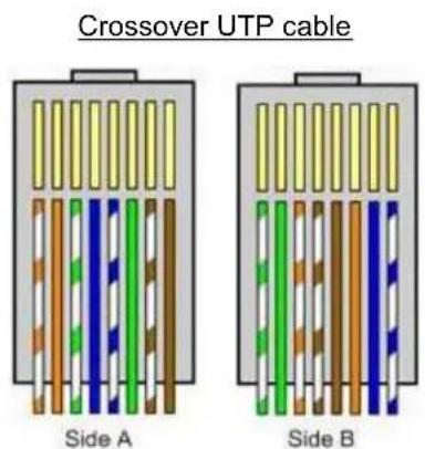
text_image
Crossover UTP cable Side A Side B2.7. How to use IR Remote Controller
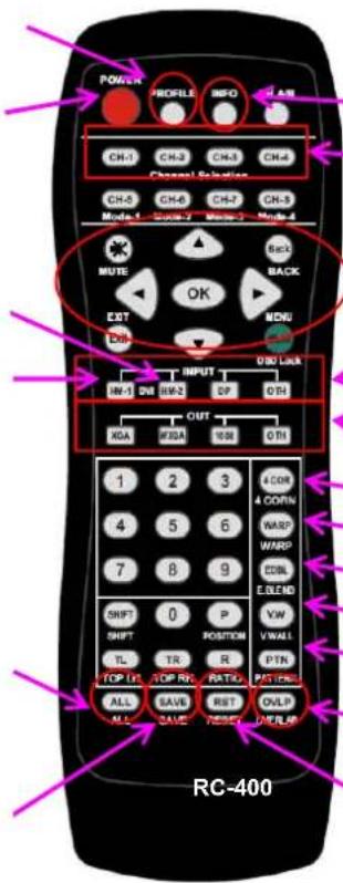
➢ IR remote controller has full functions for the operation of M800.
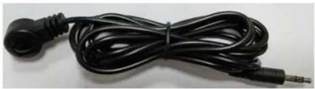
IR receiver is on Front Panel. One 3.50 mm audio connector for IR extender is located at Back Panel of M800. 1.8m IR extension cable is equipped in the packing. User can add audio cable to extend the distance up to more than 20 meters.
➢ IR remote control system is possible to be interfered and cause abnormal or discontinuous operation. Under this condition, Ethernet operation may be the best choice.
Profile [Load] shortcut key
Power on/off. If power off by remote controller, please power on by remote controller
HDMI-2/4/6/8 input port
HDMI-1/3/5/7 input port
Work with other function keys to execute function to all channels at the same time. Only some functions are available.
Profile [Save] menu
text_image
POWER PROFILE INFO LAN CH-1 CH-2 CH-3 CH-4 Channel Solution CH-6 CH-8 CH-7 CH-5 MODE 1 SODR 2 MUN 3 MUN 4 MUTE OK OUT INPUT OBO LICK IN-1 IN BIP DP OTH XOA WBA 1000 OTH 1 2 3 4 COR 4 CORN WARP WARP COSL ELEND SHIFT 0 P VW SHIFT POSITION VWAII TL TR R PTR TOP FT TOP RX RATIO PATI ALL SAVE BST ONLP ALL SAVE RESET ONFL RC-400System Information
Channel selection
OSD Menu operation keypads
Input source selection
Output resolution selection
[4 Corner] geometry alignment
[Warp] curve geometry alignment
[Edge Blend] menu
[Video Wall] Menu
Grid pattern
Video Wall [Overlap]
System reset menu
natural_image
Black cable with a metallic connector, no visible text or symbols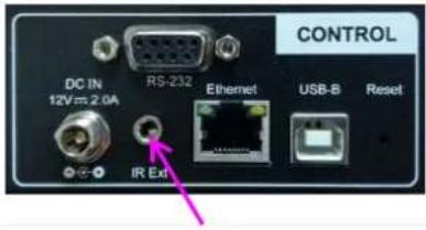
text_image
CONTROL DC IN 12V ms 2.0A RS-232 Ethernet USB-B Reset IR ExtAudio connector for IR extender
2.8. Full screen and native aspect ratio
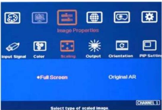
[Scaling] under [Image Properties] menu is to select the display mode either following signal source original aspect ratio or full screen display
For edge blending application, please set to [Full Screen] mode. Otherwise, there may be abnormal display in some input timing.
text_image
Image Properties Input Signal Color Scaling Output Orientation PIP Setting •Full Screen Original AR Select type of scaled image CHANNEL 1- [Full Screen]: to display full screen image no matter the input source is in what kind of aspect ratio.
- [Original AR]: the output display will keep the same display aspect ratio as signal source original aspect ratio. If the input is 4:3, then the output display will keep the same 4:3 aspect ratio.
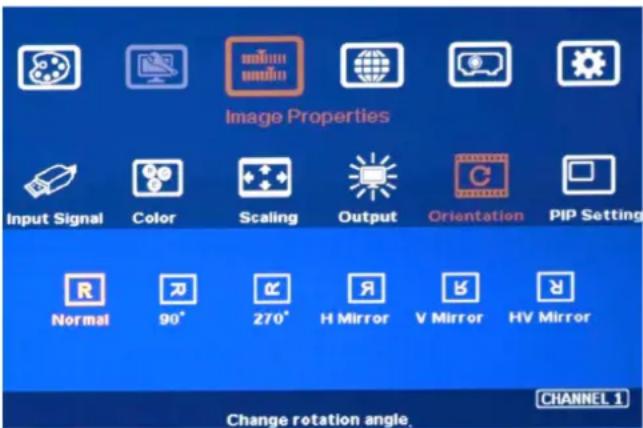
2.9. Image rotation and flip
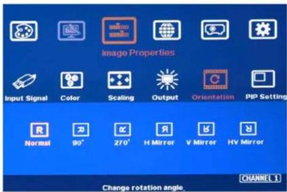
Image 90/270 degrees rotation can support up to 4k/60Hz input signal. When the image is rotated or flipped, the OSD will still keep at original direction without change. The direction for [Video Wall] settings still follow the image direction after rotated or flipped.
text_image
Image Properties Input Signal Color Scaling Output Orientation PIP Setting Normal 90° 270° H Mirror V Mirror HV Mirror Change rotation angle. CHANNEL 1- Image 90/270 degrees rotation is for edge blending with projectors at portrait position to increase image height. There is no need to rotation signal source.
- Image flip is for projector to project image from rear or top position.
- After image rotation or flip, the OSD will still keep at the original direction.
2.10. Color adjustment
In edge blending application, color adjustment is important due to multiple units of projector images are combined together.
2.10.1. Global color adjustment: [Picture]
![GeoBox M801 - Global color adjustment: [Picture] - 1](/content/2026/05/761429/images/851e4c97f47dcaab1f2b005ca9e8a23e63fd44c69c0a4698ab0fa5d2e448b34a.jpg)
text_image
Picture Brightness Contrast How Satisfaction Sharpness CHANNEL 1- [Picture] can execute below color adjustment for each processing channel.
- When input is 4:2:2 video: [Brightness], [Contrast], [Hue], [Saturation] & [Sharpness]
- When input is RGB 4:4:4: [Brightness], [Contrast] & [Sharpness]
2.10.2. Preset Color Temperature and independent RGB color adjustment
text_image
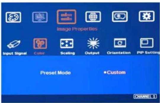
Image Properties Input Signal Color Scaling Output Orientation PIP Setting Preset Mode Custom CHANNEL 1- [Color] under [Image Properties] menu can change preset color temperature and discrete [RGB] color in each channel.
- [Preset Mode]: [Neutral], [Reddish], [Bluish]
- [Custom]: discrete RGB color adjustment
2.10.3. Color adjustment function under [Edge Blend] menu
![GeoBox M801 - Color adjustment function under [Edge Blend] menu - 1](/content/2026/05/761429/images/6eea2e3b8357a7780b226289523ff608c8e7edea25227c644eaf671d805bda58.jpg)
text_image
Anyplace 2x2 3x3 5x3 9x5 Wall Blend GWarp Edge Shift Gamma Offset Corner Color Mask Grid Change edge blending settings.Below adjustment will apply to each channel separately.
- [Gamma]: for color compensation in overlap region
- [Offset]: for black level uplift in non-overlap region (limited adjustment range)
- [Color]: for color white balance correction (limited adjustment range)
2.11. OSD Lock and unlock
If multiple units of GeoBox is installed together or the IR receiver is put together, in order to avoid interference among multiple GeoBox during the installation, user can set different ID number for each GeoBox through [Options] Menu. Press number keys in Remote Controller to determine which GeoBox will be controlled.
- 851: control GeoBox ID No. 1
- 853: control GeoBox ID No. 3
- 850: to unlock all units and user can control all GeoBox.
- User will see flashing LED on front panel after press 85x number keys. It means the OSD menu in GeoBox with flash LED is locked and will not be controlled by remote controller.
➢ OSD Lock / Unlock: When continuously press [Menu] key in IR Remote Control for 5 seconds, the OSD function will be locked to prevent from setting change by negligence. To press [MENU] key for 5 seconds again, it will unlock OSD and user can manipulate the OSD again.
2.12. System synchronization
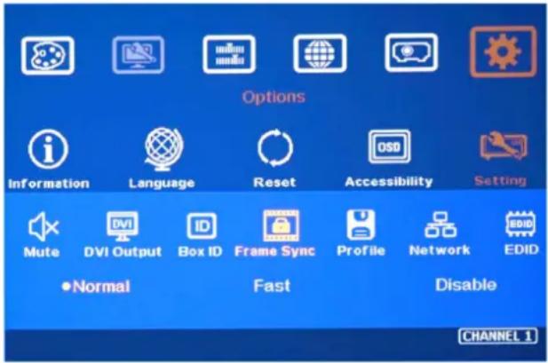
When the system uses multiple projectors, the image should be synchronized together. GeoBox uses [Frame Sync] to synchronize all outputs based on the input signal vertical sync. When [Frame Sync] is applied, it is possible to lose sync during system setup and cause the projector to re-search the signal source. In order to provide smoother setup, GeoBox provides OSD for user to select different synchronization methods for easy setup.
text_image
Options Information Language Reset Accessibility Setting Mute DVI Output Box ID Frame Sync Profile Network EDID •Normal Fast Disable CHANNEL 1➢ [Normal] (Frame Locked): when user uses multiple units of GeoBox, we propose to set at [Normal] to let all output synchronized together. The sync time will be longest. When user reset system or adjust video wall settings, user may see projector re-searching the input source.
[Fast] (Phase lock): time to sync the input source will be fast than [Normal]. However, due to projector still needs to re-search input signal, the total signal change time including projector researching will be very similar.
[Disable] (Free-Run mode): when GeoBox changes input source or timing, the output will be still running without losing any signal. The projector will not search the input source again.
There will be no loss signal when Reset or executing video wall settings. We propose user to set at [Disable] during system setup to save setup time. After finishing system settings, user needs to switch back to [Normal]. Otherwise, it is possible to have some frame tear or synchronization issue in the outputs.
If the output refresh rate is not the same as input refresh rate. The frame lock function will be disabled and it may lose synchronization among output channels. If the input is 4k/30 with FHD/60 output, it will have no synchronization problem. If the input is 50Hz, please select 1080p 50 Hz output to avoid frame repeat issue.
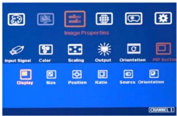
2.13. Dual window display-- PIP/POP (Picture in picture and side by side)
text_image
Image Properties Input Signal Color Scaling Output Orientation PIP Setting Display Size Position Ratio Source Orientation CHANNEL 1√ PIP: Picture in Picture
√ POP: Picture Outside Picture
√ PIP sub-image maximum size: 1920*1200
√ 90/270 image rotation is not available under PIP/POP function. Only 180 rotation of image flip is available.
√ Both main and sub-image will go through high end video processing to get the best quality.
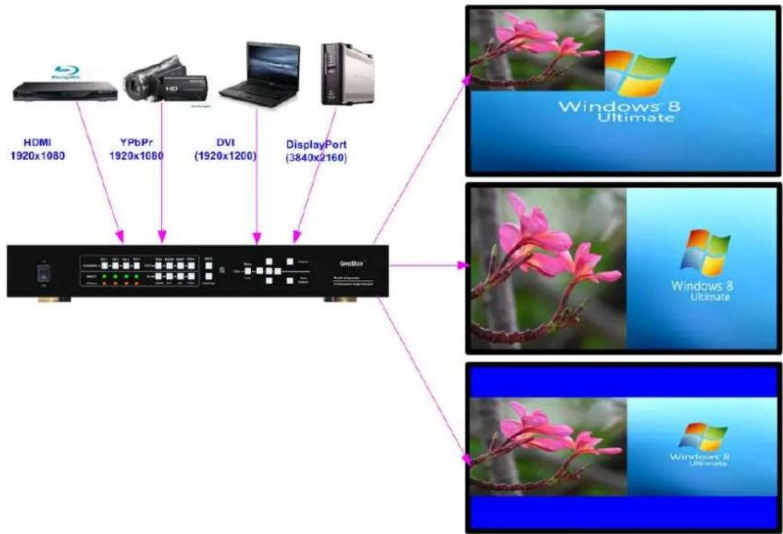
a Picture in Picture (PIP) function is to display up two images from one processing channel. The minimum size is 320*180 Pixels and maximum size of the sub-image (PIP) is 1920*1200 pixels.
b、The location of the PIP image can be controlled by OSD menu at any location inside main image.
c The size of the PIP image is also flexible and can be controlled by OSD menu.
d User can display up to 8 contents in one M804 processor. Each sub-image can only be displayed inside the display range in each projector. When execute edge blending, user needs to avoid to have sub-image in edge blending area.
e If PIP/POP image needs to be across entire screen, user needs to use the first processing channel as PIP/POP processor and output the image to HDMI port in next channel, then daisy chain connection to all processing channels. After edge blending, user can see PIP/POP across entire screen. Under this condition, the maximum system resolution will be limited to 2048x1080.
text_image
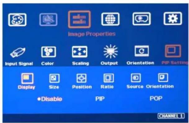
Image Properties Input Signal Color Scaling Output Orientation PIP Setting Display Size Position Ratio Source Orientation Disable PIP POP CHANNEL 1Six sub-menus under [PIP setting] menu,
--Display: enable PIP or POP
--Size: set PIP size
--Position: set PIP position
--Ratio: set PIP/POP display aspect ratio
--Source: select input source for PIP/POP
--Orientation: rotate sub-image direction
√ Display: Under Display menu, there are three items:
- Disable: disable PIP or POP function
- PIP: select PIP (picture in picture) display function
- POP: select POP (Picture outside picture / side by side) display mode. User can select main image original image aspect ratio or full screen mode through [Scaling] OSD under [Image properties].
flowchart
graph TD
    A["Device 1: HDMI 1920x1080"] --> C["Central Interface"]
    B["Device 2: YPbPr 1920x1080"] --> C
    D["Device 3: DVI (1920x1200)"] --> C
    E["Device 4: DisplayPort (3840x2160)"] --> C
    F["Windows 8 Ultimate"] --> C
    G["Windows 8 Ultimate"] --> C
    H["Windows 8 Ultimate"] --> C
    I["Input Device"] --> C
    style C fill:#f9f,stroke:#333,stroke-width:2px
√ Size: (Only apply to PIP function)
- The size of the PIP image can be adjusted though [Size] OSD menu pixel by pixel.
- The minimum PIP size is 320*180 and maximum size of PIP image is 1920*1080 pixels.
- PIP image can be displayed with full screen in the output.
√ Position: (only apply to PIP function)
- The position of PIP image can be adjusted in H&V directions through Position OSD menu.
- The PIP image will be maintained inside main image and can't be outside main image.
- Pixel by Pixel PIP image position adjustment.
√ Ratio: Set Aspect Ratio of sub-image in PIP/POP.
Full Screen: the same aspect ratio as PIP main image or full screen display in POP mode.
♦ Original AR: the same aspect ratio as sub-image input source.
- POP main image aspect ratio can be adjusted through [Scaling] under [Image Properties] OSD menu. Sub-image aspect ratio can be adjusted through [Ratio] menu under [PIP Setting].
√ Source:
- The input source for PIP/POP is selectable. Main image can be selected from [Input Signal] under [Image Properties] menu or remote controller hot key. Sub-image shall be selected from [Source] under [Pip Setting] menu.
- If user selects any HDMI input as main image, PIP or POP sub-image should come from VGA or DP input ports. Two HDMI input signals can't be selected as Main and Sub-image at the same time. If user wants to execute two HDMI input sources as main and sub-image, user needs to add one HDMI to DP adapter to connect HDMI source into DP port.
√ Rotating function combined with PIP/POP
- When PIP/POP is implemented, main image and sub-image can't be rotated at 90/270 degrees. Only 180 degrees rotation or RH/LH image flip and UP/Down flip function can be executed. Both main and PIP image will go through high end 3D motion de-interlacing.
- Main image rotation shall be executed from [Orientation] under [Image Properties] menu and Sub-image rotation shall be executed from [Orientation] under [PIP setting] menu.
- Main and sub-image can be rotated at different directions.
- When main image is 90/270 degrees rotated and user executed PIP/POP function, main image will be returned to normal display direction. Image 180 degrees rotation or flip can still be executed without change.
2.14. Image Orientation (Flip & Rotation)
√ This image orientation function will be applied to main image only.
√ User can see the direction of the TEXT "R" to do image flip and rotation.
√ OSD Menu will maintain at original direction without change.
text_image
Image Properties Input Signal Color Scaling Output Orientation PIP Setting Normal 90° 270° H Mirror V Mirror HV Mirror Change rotation angle. CHANNEL 13. Project Plan and preparation for Edge Blending
3.1. Determine source signal resolution
The image size and watching distance are two major factors to determine source signal resolution and number of the projectors.
If the screen size is 20m and the watching distance is 5m, the signal pixel pitch should be around 5mm (around 1mm for 1 meter watching distance). The system resolution is about 20m/5mm=4000. It means the system resolution should be around 4000 pixels in width and the vertical resolution should follow the projector native resolution. If 1080p projector is used, the ideal system vertical resolution is 1080.
After determine the system resolution, please make sure all the equipment in the signal pipeline should be able to support this resolution or higher. It includes signal source output, edge blending processor and the total resolution of the projectors after edge blending.
If user uses 8x XGA projector with 250 overlapped pixels, the total projector resolution after edge blending will be 1024*8-250*7=6442 pixels. It means it is enough to use XGA resolution projectors in this 20m screen case. If user uses FHD or WUXGA high end projectors with watching distance at 5m, the final video quality will be very similar as XGA projector under 4k signal source at 5m watching distance but will be better at less than 5m watching distance.
We can provide free service to help customers to make project plan, including system configuration, type of projector, signal source and installation data.
3.2. Determine overlap region size and pixels
During Excel Spread Sheet calculation, user has some flexibility to determine the overlap region size by different projector resolution, lumens and number of projectors.
The most common overlap region is about 20% to 40% based on single projector native resolution. For 1024*768 projector, the overlap range is 1024*20%-1024*40%=205\~409 pixels. GeoBox test pattern default size is 32x32 pixels. Therefore, the final result will be around 7 grids (224 pixels) to 13 grids (416 pixels) for XGA projector and 12 grids (384 pixels) \~ 24 grids (768 pixels) for 1080p & WUXGA projectors. If the projector has accurate color and gamma curve, the overlapped pixel can be lower to 5 grids (160 pixels) in XGA projector. The actual pixel number should be determined based on the required screen size and the projector model used. Under the same screen width, if higher image is required, then the overlap region will be also increased.
If the overlap pixels are increased, the image height will be also bigger. User can simulate with different overlap pixels (multiples of 32) to get a result that the image height is bigger than required image height with reasonable overlap region dimension between 50cm to 120cm in overlap region. Reasonable overlap region will be easier for overlap color control.
GeoBox maximum edge blend range is H=1920 pixels, V=1200 pixels. The black level compensation range is 900 pixels. If user requires black level uplift compensation and the
overlap region is more than 900 pixels, please select the outside black level Block to execute black level uplift. The pixel number is based on native projection area without any adjustment from either projector or GeoBox. If necessary, user can adjust the overlap size through geometry alignment to decrease overlap size without changing projector location.
3.3. Relation between Overlap pixels and geometry alignment accuracy
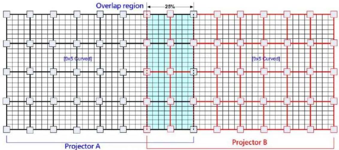
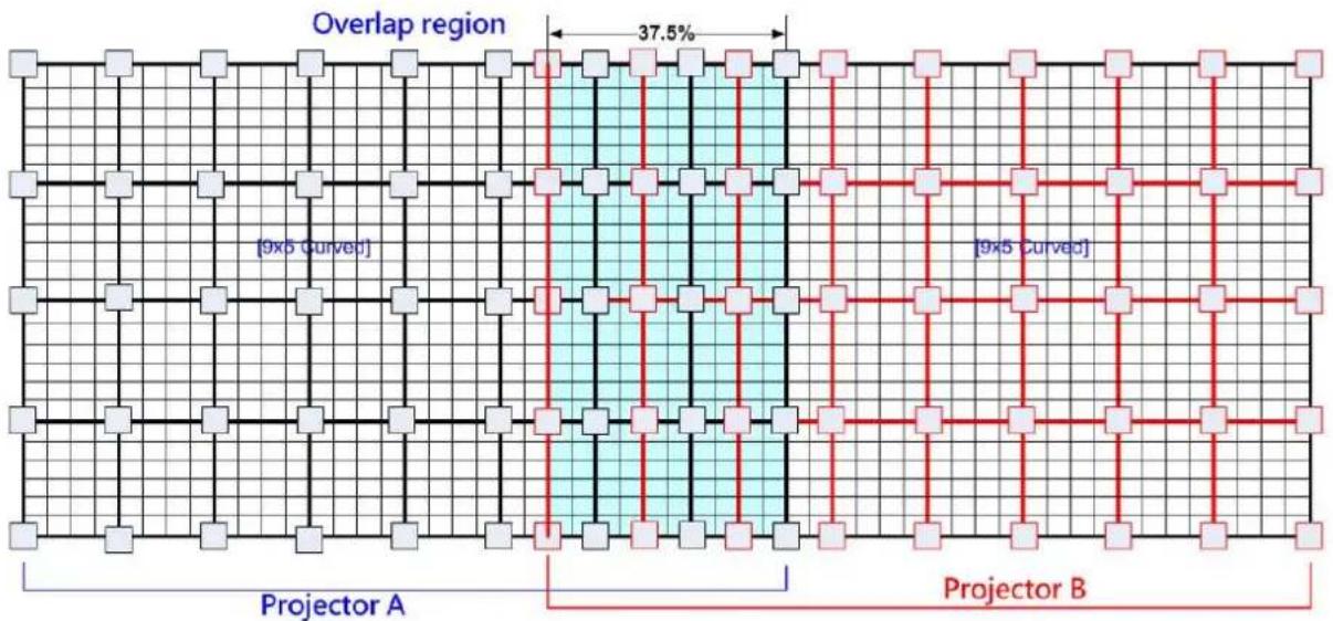
Proper selection of Overlap pixels will affect the control points in geometry alignment. If the Overlap pixel is 25% of the projector native resolution (or GeoBox output resolution), it will have less geometry alignment points due to control points in adjacent projectors will be at the same location. If the overlap pixel is not 25% of the projector native resolution, the control points will be at different positions. 37.5% overlap pixel will double the control points of the geometry alignment if compared with 25% overlap and have the best geometry alignment accuracy.
[9x5 Curved] alignment will cut the horizontal image into 8 sections and the image in each section can be independently adjusted. In different output resolutions, there will be different pixel number in each section: XGA: 1024/8=128, WXGA: 1280/8=160, 1080p: 1920/8=240. Usually, [9x5 Curved] alignment is enough for most of the curved screen edge blending.
If the overlap area between two adjacent projectors has the same or multiple number as above, the geometry alignment control points in overlap region will be less. User can increase or decrease two or three grids (64 or 96 pixels) in overlap area to increase the control points in overlap region for more accurate alignment between adjacent projectors.
Below figure is an example for [9x5 Curved] alignment in 1024 resolution:
- 25% overlap region:
The adjusting points in projector A & B will be at the same position in overlap region
text_image
Overlap region 25% [9x5 Curved] [9x5 Curved] Projector A Projector BIf the overlap is 256 pixels (25%) in XGA resolution, total adjusting points in overlap region are 3*5 = 15 . The adjusting points in projector A & B will be at the same position in overlap region. User will have less adjustment flexibility. If increasing two grids (64 pixels) to 320 overlap pixels, user can have 30 adjusting points to get more accurate geometry
alignment. It can align the images from two projectors on curved screen with good quality by remote controller.
- 37.5% overlap region
The adjusting points in projector A & B will be separated in 37.5% overlap region and increase geometry alignment accuracy.
text_image
Overlap region 37.5% [9x5 Curved] [9x5 Curved] Projector A Projector B- Recommended overlap pixels in different output resolutions
Below is the list for the accuracy of geometry adjustment in different overlap pixels:
| GeoBox output resolution | 1920*1080 | 1280*800 | 1024*768 |
| Min. adjusting flexibility | 256/480/704 | 320/480/640 | 256/384/512 |
| Max. adjusting flexibility | 352/608/832 | 224/256/384/416/544/576 | 192/320/448/576 |
3.4. Get installation data from Excel Spread Sheet
VNS can provide an Excel Spread Sheet for user to calculate necessary installation data for the project. It is important data for installation and setup.
Project basic data
| Source resolution (H) | 3840 | Screen width | 6.5 | (m) |
| Source resolution (V) | 800 | Screen height | 1.50 | (m) |
| Projector resolu. (H) | 1280 | Projector lumen | 3200 | (Lum) |
| Projector resolu. (V) | 800 | Screen Aspect ratio | 4.33 | (required) |
| Overlap pixels (32 pixels per grid) | Overlap % | Recommended | |
| Overlap pixel (H) | 256 | 20.0% | 20%~40% |
| Overlap pixel (V) | 0 | 0.0% | 25%~40% |
| Recommended overlap region: Min. 192 pixels or 50 cm width | |||
| Qty of projector (H) | 3 | Throw ratio (Min) | 1.2 |
| Qty of projector (V) | 1 | Throw ratio (Max) | 1.7 |
Final output resolution
| Horizontal resolution | 3328 |
| Vertical resolution | 800 |
| Extended pixel (H) | 98 |
| Extended pixel (V) | 0 |
^a Please apply Overlap pixels with 32x because internal grid size for geometry adjustment is based 32x32 for each grid.
Final result checking list (PJT: Projector)
| Final Image size (meter) | Final Illuminance Lux (Lum/m2) | Image size for each PJT | |||
| Width | 6.50 | PJT lumen | 3200 | Width (m) | 2.500 |
| Height | 1.56 | Final Illumin | 819 | Height (m) | 1.563 |
| Overlap region size | Original aspect ratio | Projector throw distance | |||
| Horiz (m) | 0.500 | Projector | 1.60 | Min (m) | Max (m) |
| Vertic (m) | 0.000 | Final result | 4.16 | 3.00 | 4.25 |
* Final image height should be equal or larger than screen. User can shrink image to have the same image height as screen by GeoBox geometry adjustment.
* Standard luminance is 400-800 Lux for restaurant and big conference room, 1000-1500 Lux for trade show. 3D: 500 Lux (single projector)
* Theater: 172 Lux (16 foot-lamberts), SMTP display standard: 377 Lux
* Final brightness of the screen needs to multiple gain value of the screen.
* The actual installation image size should be equal or larger than expected size.
* The best content resolution is the same as Final output resolution in cell D158.D16.
^A Illuminance: 1 Lux = 1 lumen/m2 = 0.0929 foot-candle Luminance: 1 Lumen/m2/Steradian= 1Nit = 0.29186 Foot-Lambert
Video wall setting value
| Position of projector (H) | 1 | 2 | 3 | 4 | 5 | 6 | 7 | 8 | 9 | 10 |
| LH edge overlap value | 0.0 | 98.5 | 196.9 | x | x | x | x | x | x | x |
| RH edge overlap value | 196.9 | 98.5 | 0.0 | x | x | x | x | x | x | x |
* When execute Video wall setting, user needs to connect the signal with the same resolution as [Source Resolution] in this Spread Sheet.
* When Overlap value has decimals, user can take the nearest integer value. After finishing setup, user can adjust Overlap value again to get the clearest image.
| Position of projector (V) | 1 | 2 | 3 | 4 | 5 | 6 | 7 | 8 | 9 | 10 |
| Top edge overlap value | 0.0 | x | x | x | x | x | x | x | x | x |
| BTM edge overlap value | 0.0 | x | x | x | x | x | x | x | x | x |
Below are assumptions for the above 3x projectors edge blending system Excel calculation.
√ Screen Size: 6.5m*1.5m with watching distance within 2m (pixel pitch less than 2mm)
√ Input signal resolution: 3840*800 (Pixel pitch is 6500mm/3840=1.7mm = 1.7m watching distance, optimized vertical resolution is the same as projector native resolution: 800)
√ Number of projectors: 3 projectors
√ Projector resolution and lumens. 1280*800 (native resolution), 3200 Lum
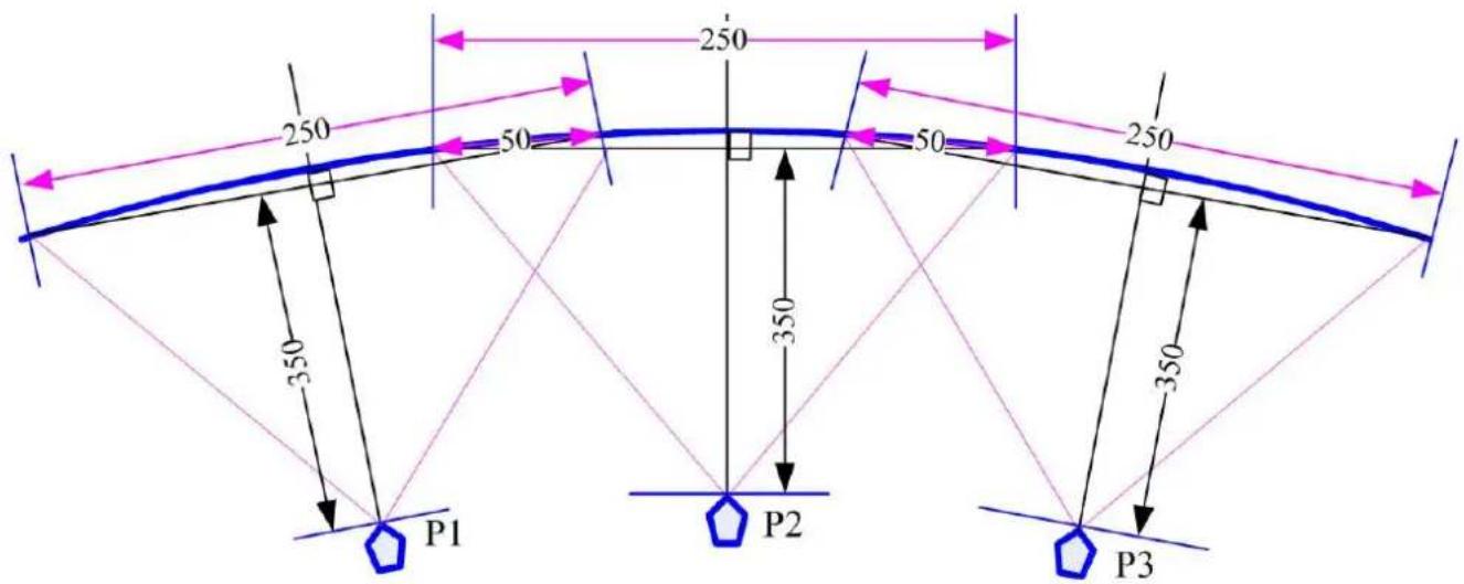
√ Overlap pixels and dimension. 8 grids=8*32=256 pixels (50cm)
√ Projector throw ratio: 1.2-1.7 (based on projector spec)
How to operate VNS Excel Spread Sheet
√ Input all the data in Yellow column, including Source Resolution, Projector Resolution (GeoBox output resolution), Screen size, Projector throw ratio, Projector Lumens, No. of projector and Overlap Pixels. User can try different configurations and select most cost effective one with minimum image height is higher than required.
√ User will get below data from the Spread Sheet.
- Final image size for each projector is 250cm*1.56cm with Overlap region of 50cm in width.
- The image height should be higher than the required one. User can shrink the vertical height to required dimensions through geometry alignment. The vertical adjustment range in each edge is 600 pixels.
- Optimized content resolution: 3328*800 (This is the ideal resolution to set EDID). It is suggested to select the same vertical resolution (800) as projector native resolution to get the best result.
■ Installation distance: 3m-4.25m.
It is calculated from throw ratio and image wide for each projector. (2.5m*1.2=3m, 2.5m*1.7=4.25m)
■ The overlap value in Video Wall setting:
- When user sets Video Wall Zoom, it will split the image equally for each projector. The projectors will be installed with some Overlap Pixels for edge blending. Therefore, Overlap Value is to crop more pixels for each section based on the Overlap size between two adjacent projectors.
- LH Projector: select RH edge: +197 (to crop more 197 pixels for LH projector. These 197 pixels are based on source resolution.
- Projector (Center): LH edge=+98, RH edge=+99 (total 197)
- RH Projector: LH edge: +197
- After finish setting, user can check the image, if some overlap area is blurred, user can increase or decrease Overlap Value with 1-2 pixels and select optimized one.
The final luminance is 819 Lux. It will be enough for inside room environment.
√ It is allowed to have different overlap pixel among projectors. "Irregular" Spread Sheet is required to calculate the data.
√ Please contact dealer or factory to get necessary assistance for the Spread Sheet.
3.5. Apply Spread Sheet data for projector installation and GeoBox setting
3.5.1. Installation data from Spread Sheet from previous section:
√ Image size for each projector: 250cm *156cm
√ Overlap region: 50cm
√ Installation distance based on throw ratio 1.1-1.7: between 300cm-425cm
√ Installation height: install the projector at a position with minimum keystone at both vertical edges.
3.5.2. Mark projection region for each projector
√ Based on the calculation data, user can easily determine the image location for each projector.
√ Using laser Level tool and mark the locations for each projector with paper tape, including 4 borders and center line of the screen. The paper tape shall not damage the surface of the screen.
text_image
250 250 50 50 250 350 350 350 P1 P2 P33.5.3. Installation the projector
√ To install the projector at a location as showed above with the image just a little over required region at any point. Too large image will lose image resolution and brightness.
√ Minimum keystone effect will optimize the image quality with less geometry alignment.
√ The image height from the projector can be higher than required and user can draw down the image height through geometry alignment. The adjusting range is up to 1200 pixels in the top and 600 pixels in bottom edges. If the bottom edge needs more adjustment range, please flip the image in the projector so that the bottom edge will become top edge and get larger geometry alignment range.
natural_image
Red and black industrial water leveling device with blue filter (no visible text or symbols)During the installation, Laser Level is a good tool to get correct horizontal and vertical line and make sure each projector can cover correct display
3.6. Projector settings before edge blending
➢ Please reset all projectors to factory default settings.
➢ Set to ceiling mount if necessary.
➢ Disable below items:
Auto keystone, auto aspect ratio, auto color compensation, auto source searching
Select a display mode with gamma 2.2 or standard display mode. After edge blending, if user still sees some banding in overlap region, please select the best one from different display modes.
If there is color deviation among projectors, please try to correct color difference through projector color adjusting function to let all color as close as possible.
➢ Enable [multiple projector display] mode in some projector model.
3.7. GeoBox settings before edge blending
Use small pin to insert into RESET hole on the back panel of GeoBox for 5 seconds to reset GeoBox to default setting. [Reset] will apply to all channels at the same time.
➢ Select channel number, then select input port and output resolution separately.
Set output resolution to be the same as projector native display resolution. Each channel shall set output resolution separately.
Connect with a signal source to HDMI-1 in CH1, then connect loop out port to CH2 HDMI-3 through HDMI cable. If CH3 and CH4 are required, please connect the loop out port to HDMI-5 and HDMI-7 with HDMI cable to let all processing channel feed with the same signal source.
The signal source for installation should be no less than 1080p.
➢ Check input/output LED indicators and make sure to have correction system connection.
User can set [Frame Sync] at [Disable] to eliminate [Source-Search] in projector during setup. After finish the setup, user needs to set to [Normal] to get synchronization in all outputs.
4. Geometry alignment
4.1. Select the right Grid Pattern for geometry alignment
Grid pattern is required for geometry alignment. User can activate test pattern through [Pattern] hotkey in remote controller or through WebGui and Gwarp3 PC tool.
The default grid size is 32*32 pixels. User can select different grid size from 8-120 pixels.
The show-up time can be determined by [Options]→ [Accessibility]→ [Menu Time Out]. If set at "0", the OSD and pattern will show up all the time unless input timing is changed or OSD [Exit].
If user finds different grid size in different projectors, please check the grid pattern size, output timing setting and the aspect ratio settings in each projector. GeoBox needs to set at [Full Screen] display mode under [Image Properties]→[Scaling] menu.
If user executes Geometry alignment, the pattern will appear automatically after select the adjusting point and press Enter.
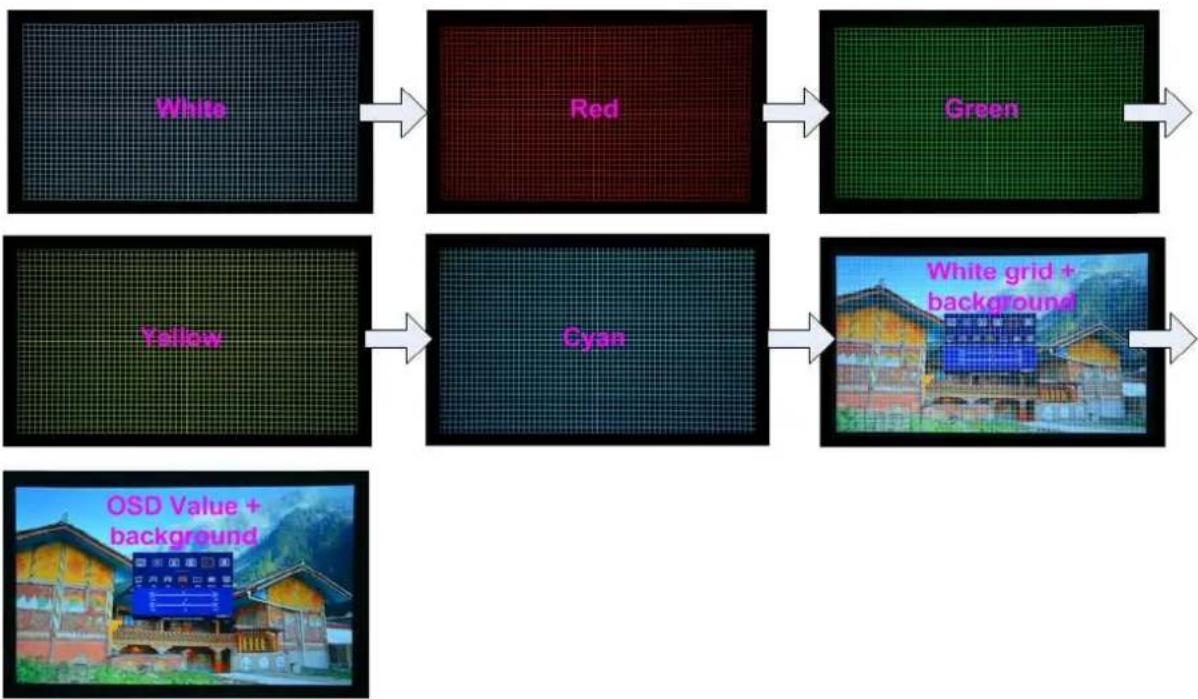
There are 6 pattern styles for user to select. When user presses [Pattern] key, it will circulate from [White]→ [Red]→ [Green]→ [Yellow]→ [Cyan]→ [White grid + background]→ [OSD menu + Background]
If user wants to apply his own test pattern, please select the last transparent pattern mode to show up background user pattern.
➢ User can select different pattern color while doing edge blending for easy setup.
Note: some projector RGB points are not at the same location. It will cause position deviation. Please recheck with White grid pattern for final result.
➢ User can see geometry adjusting value when select [Background + OSD] display style.
flowchart
graph LR
    A["White"] --> B["Red"]
    B --> C["Green"]
    D["Yellow"] --> E["Cyan"]
    E --> F["White grid + background"]
    G(OSD Value + background) --> F
4.2. Grid pattern pixel size selection
The pixel size in grid pattern for geometry alignment is selectable to meet high end simulation system geometry alignment requirements. The grid size in both horizontal and vertical directions is from 8 to 120 pixels with 1-pixel increasement. H&V grid size will be the same. User can select grid size under [Edge Blend] menu.
➢ Default grid size for both H&V directions are 32x32.
If 120 pixels grid size is selected, the grid pattern will be at the same position as 17x17 geometry adjustment control points. If 30/60 pixels grid size is selected, the grid pattern will also have some points that will match 17x17 control points. It will be convenient for some application.
In order to get optimized result in video wall [Overlap] value, user can use VNS Excel Spread Sheet and apply an overlap pixel in the Spread Sheet to get a near integrate number in Video Wall [Overlap] value, then select the grid size to match this overlap pixel.
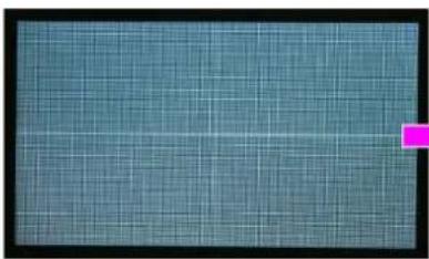
In low resolution projector with low overlap grid number, user can select a grid size to maximized the overlap region to improve edge blending quality. For example, when the overlap pixel is only 186 pixels, if user selects 32x32 pixels as grid size, then user needs to reduce the grid size to only 160 pixels (5 grids) to let the grids from adjacent projector to stack together. If user selects a grid size of 31x31, then user can keep 186 pixels (6 grids) as overlap pixels.
natural_image
Close-up of a teal-colored grid pattern with a magenta square overlay (no text or symbols)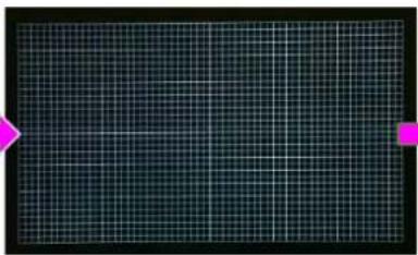
natural_image
Dark grid pattern with faint horizontal lines and a pink arrow pointing to the left edge (no text or symbols)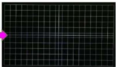
natural_image
Grid pattern with a magenta arrow pointing to the bottom-left corner (no text or symbols)Below is the OSD menu for the selection of grid size.
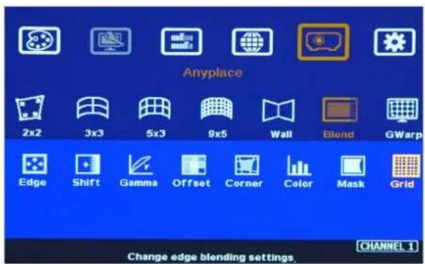
text_image
Anyplace 2x2 3x3 5x3 9x5 Wall Blend GWarp Edge Shift Gamma Offset Corner Color Mask Grid Change edge blending settings.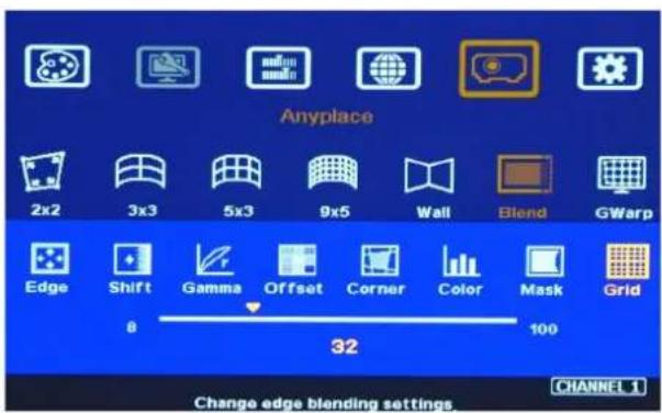
text_image
Anyplace 2x2 3x3 5x3 9x5 Wall Blend GWarp Edge Shift Gamma Offset Corner Color Mask Grid 8 32 100 Change edge blending settings CHANNEL 14.3. Geometry alignment
Geometry alignment is to align the image position to let the projection image match the screen and also let image grids between two adjacent projectors be combined together. This step will take most of the time for edge blending. User can execute geometry alignment through remote controller, Gwarp3 PC tool or WebGui through Ethernet connection.
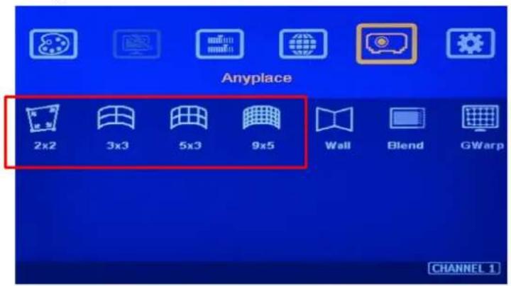
text_image
Anyplace 2x2 3x3 5x3 9x5 Wall Blend GWarp CHANNEL 1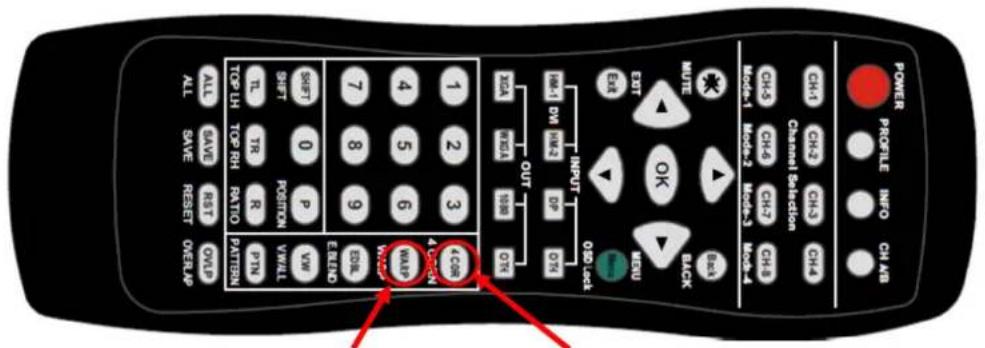
text_image
POWER PROFILE INFO CH AB CH4 CH2 CH3 CH4 Channel Selection CH4 CH6 CH7 CH8 MOU-1 MOU-2 MOU-3 MOU-4 OUT HMI DM HMI3 DP D5I WISA 1980 OTR EXIT OK MISU BACK 0.00 Lock SHIFT 0 P SHIFT POSITION TLC TR R TOP LH TOP RH RATIO ELENO VWM VWALL PIN PATTERN ALL SAVE REST OVID ALL SAVE RESET OVERLAP[3x3], [5x3], [9x5] Warp hotkey
[2x2] 4 Corner hotkey
4.3.1. Geometry alignment through remote controller
√ Please be familiar with OSD operation from remote controller, including activating grid pattern, channel switching and hot keys for [4 Corner], [Warp], [Video Wall], [Edge Blend], [Pattern] and [Info].
√ [OSD Time Out] is default to "0". It will ensure the grid pattern will not be turned off automatically. Input mode change will disable OSD and grid pattern.
√ User can install IR extender receiver near screen for easy GeoBox operation (if necessary, please add audio extending cable to extend the distance up to 20 meters). If multiple units of GeoBox are used and IR receivers are put together, please set [Box ID] for each M800 so that user can control each M800 separately through [85x] command. Press number keys in Remote Controller following OSD menu for the control of multiple GeoBox:
- 850: will activate all GeoBox. User can execute simultaneous control for all GeoBox
- 851: activate only ID #1 GeoBox for further control.
- 852: activate only ID#2 GeoBox for further control.
√ Each channel should execute geometry, video wall setting and edge blending setting separately.
4.3.2. Activate Grid Pattern
√ Use channel selection keys and [Pattern] hotkey to show grid patterns in all projectors. Press [Pattern] key again will change grid color. To set two different pattern colors in adjacent projectors will be more convenient during geometry alignment.
√ If user finds the grid size between adjacent projectors is different. Some possibilities:
- The projection image sizes between two projectors are different (Zoom setting or projection distance is different).
- Output resolution settings in different GeoBox are not the same.
- Projector aspect ratio setting is different or not set at full screen display.
- GeoBox is set at [Original AR] under the menu of [Image Properties]→ [Scaling] menu.
- Set different grid pattern size in each channel.
If user doesn't use Excel file to calculate the image size in each projector, please try to set the same projection height prior to geometry adjustment. In this case, the image width and overlap grid size for all projectors will be also similar and is ready for further geometry alignment.
4.3.3. [2x2] 4 corner geometry alignment
√ No need to do keystone correction in the projectors before geometry alignment unless the image has too big distortion and GeoBox can't cover the alignment range.
√ [2x2] alignment will adjust whole image with the same scaling factor. [War] alignment will adjust only some portions of the image.
√ Please follow the sequence [2x2][3x3][5x3][9x5] to do geometry alignment to ensure entire image will have uniform scaling factor.
√ Apply [2X2 Corner] geometry alignment and draw the corners to pre-marked locations.
√ If no pre-marked location, please use [2×2] alignment to let the image in each projector with the same horizontal position and also let the vertical borders without keystone.
√ Measure the image size in each projector, to reduce the size of the larger image at top edge through [2×2] alignment and let both projectors have similar grid size and number in overlap area. Then to adjust the bottom edge corner point to follow top edge vertical position.
√ If the screen is curved, it is possible to have some image inside or outside the screen after 2x2 adjustment. However, it doesn't matter once the image covers entire screen before 4 corner adjustment. [Warp] alignment will adjust the image position back to required position.
![GeoBox M801 - [2x2] 4 corner geometry alignment - 1](/content/2026/05/761429/images/08c3ae6e2448d9a7e2c45c7875a1446c12060d2adab41e0b5060a4d889b552dd.jpg)
text_image
Anyplace 2x2 3x3 5x3 9x5 Wall Blend GWarp Reset Adjusts image position by four corner. CHANNEL 1[2x2] 4 Corner hotkey
![GeoBox M801 - [2x2] 4 corner geometry alignment - 2](/content/2026/05/761429/images/f902c7203e28dbd45fa6eac181d139ba75734143aebbdea180a2db26fafa13eb.jpg)
text_image
AT200 LEEK BNT TV ON ON ON ON ON ON ON ON ON ON ON ON ON ON ON ON ON ON ON ON ON ON ON ON ON ON ON ON ON ON ON ON ON ON ON ON ON ON ON ON ON ON ON ON ON ON ON ON ON ON OK OK OK OK OK OK OK OK OK OK OK OK OK OK OK OK OK OK OK OK OK OK OK OK OK OK OK OK OK OK OK OK OK OK OK OK OK OK OK OK OK OK OK OK OK OK OK OK OK OK AKS4.3.4. [3x3], [5x3], [9x5] Warp alignment
√ After finish [2x2] corner alignment, apply [3x3 Curved] geometry alignment to let 9 adjusting points be located at the required position including four corners, edge center points and center line position.
![GeoBox M801 - [3x3], [5x3], [9x5] Warp alignment - 1](/content/2026/05/761429/images/01d1d30795c1a732923ba030b4595bdeb49a57c52befdfef8d874a89ad11dcca.jpg)
text_image
Anyplace 2x2 3x3 5x3 9x5 Wall Blend GWarp Reset Change curved surface settings CHANNEL 1[3x3] warp hotkey
![GeoBox M801 - [3x3], [5x3], [9x5] Warp alignment - 2](/content/2026/05/761429/images/c73032091f9aa434cad7c56b3fa5c9a86e9998ed1f58cc7337816e02ab7f6ad4.jpg)
text_image
AT830 1228 VOL ON ON ON ON ON ON ON ON ON ON ON ON ON ON ON ON ON ON ON ON ON ON ON ON ON ON ON ON ON ON ON ON ON ON ON ON ON ON ON ON ON ON ON ON ON ON ON ON ON ON OFF POWER PRESS INVO GAM√ Please use [5X3] & [9x5] for further geometry alignment and let all the grids in overlap area with good grid stacking from two projectors.
√ For curved screen, if there is some difference in the grid size in adjacent projectors, user can use [9 × 5] Linearity Grid Line adjustment (in next section) to adjust the grid size and finish the image position fine tune.
√ After finish Warp alignment, user can use [2x2] for complete image position fine tune without changing the Warp result. If user executes [3x3] alignment again after [9x5] alignment, [9x5] grid position will be reset and only keep [3x3] grid point information.
√ All the horizontal lines in the grids should match complete.
√ In ideal condition, all grids in edge blending area between two adjacent projectors should be aligned together. In some special case, the vertical lines in edge blending area have some gap and can't match 100%. Please try to align the grids near center overlap region with good stacking. It allows small image shift in both sides of the overlap region because edge blending will reduce the effect for the mis-alignment in side borders. User can also adjust [Overlap] value in video wall settings to compensate this deviation and keep reasonable image quality.
√ After the above processes, if the grid pattern in edge blending area still can't stack together, user can reduce one or two overlap grids from adjacent projectors to separate the adjusting points in each projector and get more accurate geometry alignment result. If the result is still not good, please use [Gwarp3] PC tool to apply 17x17 grid point adjustment.
√ Geometry alignment range from remote controller can be up to 600 pixels in [2×2] + 600 pixels more in [3×3] for one corner/edge. If necessary, please use projector geometry alignment function to do some adjustment.
(Important notice: Geometry alignment range in bottom edge will be smaller due to hardware limitation. In 3x3 warp alignment in bottom edge, if the adjusting pixels number in more than 300 pixels, the image may have noise occurred. In actual project in curved screen edge blending, the limitation will not happen because the projectors are installed at ceiling with image top/down flip, after image flip to normal direction, the bottom side of the image will be located at top edge in geometry alignment.)
√ After geometry alignment, all the grid patterns in overlap region should be stacked together.
![GeoBox M801 - [3x3], [5x3], [9x5] Warp alignment - 3](/content/2026/05/761429/images/eb265720012d0b5396061d8e3824251e7c1009914497fd85049770f33dd19728.jpg)
natural_image
Grid of green and black square patterns with no text or symbols4.3.5. Linearity grid line adjustment
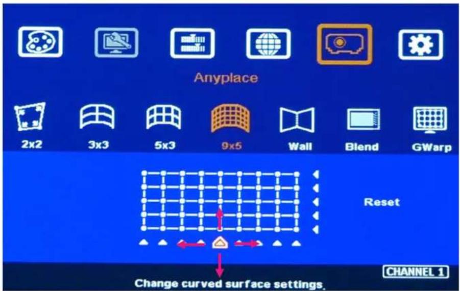
text_image
Anyplace 2x2 3x3 5x3 9x5 Wall Blend GWarp Reset Change curved surface settings. CHANNEL 1The control point can shift the lines in both horizontal and vertical directions.
√ Linearity grid line adjustment menu is under [9x5] warp alignment in OSD. User can select the control point, then press ENTER to see complete grid line for the adjustment. Each control point can shift the image in both horizontal and vertical directions.
√ When user projects the image to curved screen using projector, the image grid size will continuously change—the grid size at the center will be bigger than both sides. Ultra-short throw projector will be more serious. This function is mainly designed to correct this kind of grid size difference.
√ Linearity Grid Line adjustment can be applied to horizontal lines and vertical lines. The maximum adjusting points in OSD menu is H=9, V=5. If it is executed through Gwarp3 PC tool, it will have from 3x3 to 17x17 control points in H&V directions.
√ The control points can move all the lines in the control region with the same distance at the same time. It can also move the grid line at vertical direction.
√ This function can co-work with Warp and Edge Blending function.
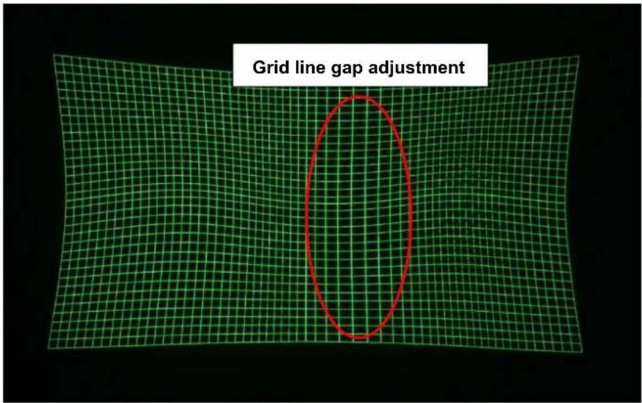
text_image
Grid line gap adjustment4.3.6. Corner Wall geometry adjustment
Important note: When apply Corner Wall function, all the other geometry alignment function will be disabled. User can only execute geometry alignment through 8 points of Corner Wall adjustment. 4 corner control points can execute image 4 corner alignment same as [2x2] geometry alignment function. Edge Blend function will be still available.
Corner Wall alignment allows user to adjust the image at wall corner. It can execute horizontal and vertical corner alignment. User can select either horizontal or vertical alignment at one time. This function can co-exist with edge blending function but not warp function. The image position can be adjusted as below:
√ 4 corner image positions
√ The transition position of the image in horizontal or vertical direction
√ The maximum Corner adjusting range is +_900 pixels and the location adjusting range is +_900 pixels.
√ The image will keep the same grid size (scaling factor) automatically.
User can't use ultra-short throw ratio projector for corner wall application. Otherwise, the image distortion will be too big to be adjusted and may also create focus issue.
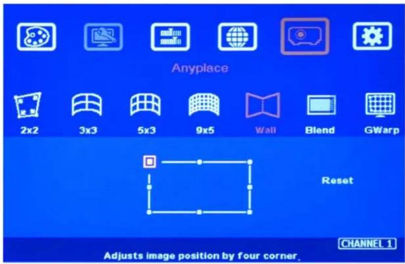
text_image
Anyplace 2x2 3x3 5x3 9x5 Wall Blend GWarp Reset Adjusts image position by four corner. CHANNEL 1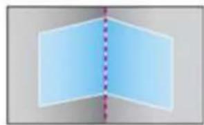
natural_image
Abstract geometric shape with a vertical dashed line dividing two light blue rectangles (no text or symbols)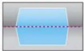
natural_image
Simple 3D geometric shape with a dashed line crossing through it (no text or symbols)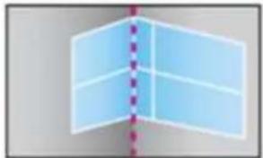
natural_image
Abstract 3D geometric shape with a vertical dashed line and shaded planes (no text or symbols)
natural_image
Abstract geometric shape with blue rectangular blocks and a vertical dashed line (no text or symbols)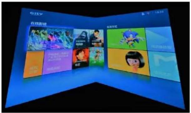
Example A: Single projector application
natural_image
Illustration of a pink box with purple floral design and 'PARKING' text label (no other readable symbols or text)
natural_image
Illustration of a historical scene with figures in traditional attire, stone buildings, and a boat on water (no visible text or symbols)Example B: Dual projector application
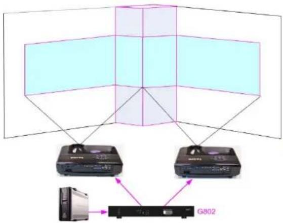
flowchart
graph TD
    A["Device G802"] --> B["Device"]
    C["Device"] --> D["Device"]
    style A fill:#f9f,stroke:#333
    style C fill:#ccf,stroke:#333
    style B fill:#cfc,stroke:#333
    style D fill:#fcc,stroke:#333
Example C: Three projector application
natural_image
Interior of a modern exhibition space with illuminated geometric panels and a central circular display (no visible text or symbols)Corner wall application on curved screen
If user wants to implement Corner Wall function on curve screen, user can connect the signal to one channel in M800 to do warp alignment, then connect the output to the input port of the channel for Corner Wall alignment. Then user can execute curve alignment and Corner Wall adjustment at the same time.
4.3.7. [Gwarp3] PC Tool
√ User can use USB or Ethernet to control M800 through Gwarp3 PC tool. The operation in the Gwarp3 will be executed directly into GeoBox in real time. User can combine the operations in Gwarp3 together with remote controller or front panel keypads to finish all settings for edge blending.
√ After fiish [Warp Adjust] in Gwarp3, user can save the settings into [UserMap] through [Save to Box]. There are totally 10 UserMaps for user to save different geometry alignment result in different application. User can recall this UserMap geometry settings from OSD menu under [Anyplace].
![GeoBox M801 - [Gwarp3] PC Tool - 1](/content/2026/05/761429/images/f14ea9f898454ed9a5197441778bbadba34a534c89cecd4f258e63a91be0d4e6.jpg)
text_image
Anyplace 2x2 3x3 5x3 9x5 Wall Blend GWarp UserMap1 UserMap2 UserMap3 UserMap4 UserMap5 UserMap6 UserMap7 UserMap8 UserMap9 UserMap10 Finetune CHANNEL 1√ Once user selects企业在Map setting, then other geometry alignment will be reset and replaced with企业在Map setting.
√ UserMap only stores geometry alignment setting. This setting can be used with other functions to achieve edge blending or other purposes.
√ If user doesn't store any Gwarp3 setting to UserMap, when user clicks any UserMap menu or select one UserMap without storing any Gwarp3 data, user may not see any image on the screen. Under this condition, please press [2x2] geometry alignment hotkey on remote controller to see OSD menu on the screen and execute further operations.
√ [Finetune]
If the system is installed based on Gwarp3 geometry data which is saved in UserMap, user still can execute small position modification through [Finetune] menu. This 4 corners position adjustment range is +-50 pixels for each corner. This function is important for after service and while changing lamp to return the image to original position.
5. [Video Wall] setting
After geometry alignment, it is required to crop the image and assign to each projector. Each channel shall execute [Video Wall] settings separately.
The purpose for Video Wall Setting is to determine the display Matrix, split the image and assign the right image to each GeoBox/display device in the matrix. The overlap pixel between two images can be adjusted pixel by pixel. The maximum video wall can be up to 15x15 matrix display.
◇
![GeoBox M801 - [Video Wall] setting - 1](/content/2026/05/761429/images/91490177ae02deaeb1a12b87607da6a6ce8248aa69ccb672569b5d9132bc8e34.jpg)
text_image
Video Wall Zoom Pan Overlap Position CHANNEL 1- Press Menu Keypad on Front Panel or remote controller to enter [Video Wall] OSD menu.
- [Video Wall] hotkey on the bottom right position of the remote controller is available for quick access.
- Video wall function can crop image for edge blending and assign to projectors.
![GeoBox M801 - [Video Wall] setting - 2](/content/2026/05/761429/images/cac7c7fedde266ad91707b1302c58c93d827f11e1e2b4ed6eff56eba1c08e2ba.jpg)
text_image
POWER PROFILE INFO CH AM CH-1 CH-2 CH-3 CH-4 Ch-3 Ch-4 Ch-5 Ch-6 Mode-1 Mode-2 Mode-3 Mode-4 MUTE EXIT OK RNU BACK INH-1 ON IRE2 SP GS OUT 20A MEDIA SBB GS 1 2 3 4 5 6 7 8 9 4 CORN WARP ESBL WARP EASEL VW SWI SWEET SHIFT POSITION TL TIR R TOP LH TOP RH ANTIO ALL SAVE RESET OVERLA# ALL SAVE RESET OVERLA#[Video Wall] menu hotkey
5.1. [Zoom]: split the signal source
![GeoBox M801 - [Zoom]: split the signal source - 1](/content/2026/05/761429/images/828ad569e62bddf484d0369fdc3a4b4d1ce0b32e9f57ffb8bc66e9ae9749d31b.jpg)
text_image
Video Wall Zoom Pan Overlap Position Horizontal Zoom Vertical Zoom 1 1 15 Change the zoom settings. CHANNEL 1Use [Zoom] to split input image in horizontal and vertical directions. Maximum split images are 15x15 in both horizontal and vertical directions from single input source.
![GeoBox M801 - [Zoom]: split the signal source - 2](/content/2026/05/761429/images/8b5978cc0c3b0141f8060f1443a12a61d120cf4f99e37c6c180cc9a615c6e4d1.jpg)
For 3 projectors at horizontal position, Horizontal Zoom=3, Vertical zoom=1
![GeoBox M801 - [Zoom]: split the signal source - 3](/content/2026/05/761429/images/2504d3dab2faec92b3565ae16ce499318f01fc0223ca1f3d6b3e02ae3ebe0516.jpg)
text_image
① ② ③ ④ ⑤ ⑥ ⑦ ⑧ ⑨For 3x3 displays (9 projectors), Horizontal Zoom=3, Vertical Zoom=3
5.2. [Pan]: assign image location
![GeoBox M801 - [Pan]: assign image location - 1](/content/2026/05/761429/images/17fbbb7d48bdf7f55226f5e13572a1a1f552bab9c265fb90541f9c4acedb1436.jpg)
text_image
Video Wall Zoom Pan Overlap Position Horizontal Pan Vertical Pan 1 15 CHANNEL 1 Select the zoom window by panning.- Use [Pan] to determine the location of each split image in both horizontal and vertical directions.
- Default setting: Horizontal Pan=1 Vertical Pan=1
![GeoBox M801 - [Pan]: assign image location - 2](/content/2026/05/761429/images/df43aeb3289d1bc13dcb556e3611c1937330b7e2c97e25e7fa559e94819807e1.jpg)
text_image
① ② ③ ④ ⑤ ⑥ ⑦ ⑧ ⑨For No. ③ projector: For No. ⑥ projector:
Horizontal Pan = 3
Horizontal Pan = 3
Vertical Pan = 1
Vertical Pan = 2
5.3. [Overlap]: crop the right image for each projector
![GeoBox M801 - [Overlap]: crop the right image for each projector - 1](/content/2026/05/761429/images/b8352169105ce98d69245328207a17c847dde23201677835fd3b3c1cd4eb32bf.jpg)
text_image
Video Wall Zoom Pan Overlap Position ● Left Edge Right Edge Top Edge Bottom Edge Reset -900 0 900 Adjust overlap setting CHANNEL 1- Use [Overlap] to determine overlapped pixels between two adjacent projectors. It will change image cropping area and can change image aspect ratio.
- In projector edge blending, user needs to select correct Edge and crop the right overlapped pixels for each projector.
- Max. Overlap range is + 1800 Pixels
In multiple projector applications, if the overlap region has different size due to installation position limitation, the overlap value may be different between projectors. However, the total overlap value should be the same to maintain the same scaling factor.
➢ Please use Irregular Excel Spread Sheet to calculate overlap value in the above irregular overlap pixel condition.
User can use Video Wall overlap setting to fine-tune the image in overlap region. It can compensate geometry mis-alignment and let image become much clearer.
5.4. [Position]: shift image position without changing image size
After cropping, user can shift image position at H&V directions without changing image size. Usually, it is for video wall application to fine tune image position. In projector edge blending application, user only changes Overlap value in one edge but not execute image shift.
![GeoBox M801 - [Position]: shift image position without changing image size - 1](/content/2026/05/761429/images/846581d86d177f8b3d66dcca5ea75825b1dbc7a7c5db519e7ca8d14df7062f8a.jpg)
Edge Blend is to merge the images from multiple projectors to become one seamless image.
The scaling factor between two adjacent images shall be the same. It means the image size under the same resolution should be the same.
- Geometry alignment is required before edge blending:
- To let the image has the same grid size (same scaling factor in both horizontal and vertical directions)
- To let images overlapped together in horizontal lines and vertical lines.
Sub-menu under [Edge Blend] menu
- [Edge]: select the right edge and set overlap pixels. The pixel no. is same as the overlap grid size multiple grid number. If overlap is 10 grids, the overlap pixel is 320 in default grid size.
- [Shift]: to shift image edge location and implement [Edge Mask] function for non-overlapped edges with black background.
- [Gamma]: adjust gamma value in [Transition] and [Gain] in each channel to improve banding effect in overlap region.
- [Corner]: to do precise [Offset] location alignment.
- [Offset]: to do black level uplift in non-overlapped area to compensate light leakage in projectors.
- [Color]: to do White Balance correction for individual projector.
![GeoBox M801 - [Position]: shift image position without changing image size - 2](/content/2026/05/761429/images/0e869dd3430f4b530e44c17ea9b210fea552c2f437777709235dcc474fed5bac.jpg)
text_image
POWER PROFILE INFO CH AB CH1 CH2 CH3 CH4 Channel Selection CH-5 CH-6 CH-7 CH-8 Mode-1 Mode-2 Mode-3 Mode-4 MUTE EXIT OK BACK Erie OBD Lock HRL DH HRS DP OTR XQA VIDA RBD OTR 1 2 3 4 CORN 4 5 6 WARP WZ20 EDBL F-ERIO SHIFT 0 P VW SHIFT POSITION V/WALL TL TR R PTN TOP LH TOP RH RATIO PATTERN ALL SAVE RST OVLP ALL SAVE RESET OVER LP[Edge Blend] hotkey
![GeoBox M801 - [Position]: shift image position without changing image size - 3](/content/2026/05/761429/images/b2ae769721a5b07dca9bf44fe46de761367737896c96ab6d11128812405285b6.jpg)
text_image
Anyplace 2x2 3x3 5x3 9x5 Wall Blend GWarp Edge Shift Gamma Offset Corner Color Mask Grid Change edge blending settings.6.1. [Edge]: select location and set edge blending value
➢ [Edge] is to select the edge for edge blend and set overlapped pixel number.
➢ User can execute edge blending at any edge.
➢ Maximum edge blend pixels are H=1920, V=1200.
Color indicating lines will appear when set edge blending pixels.
User needs to adjust the color indicating lines to match together (green to green, red to red). The final overlap value is the same as actual overlap number (grid size * grid number).
![GeoBox M801 - [Edge]: select location and set edge blending value - 1](/content/2026/05/761429/images/f05bf54aa879d9433b8c711138efbac29273dc61d6736078af4afecc650629f9.jpg)
text_image
Anyplace 2x2 3x3 5x3 9x5 Wall Blend GWarp ● Left Edge Right Edge Top Edge Bottom Edge Reset 0 0 1920 Change edge blending settings. CHANNEL 1For 3 projector edge blending as example:
- To select [Right Edge] for LH projector
- To select both [Right Edge] & [Left Edge] for center projector.
- To select [Left Edge] for RH projector
6.2. [Shift]: shift image position and execute Edge Mask
[Shift] has two functions: one is to shift [Edge Blend] location and another function is to do [Edge Mask] in not [Edge Blend] borders.
When user selects the edge with [Edge Blend], user can apply "+" value (0 to +500) to shift the whole [Edge Blend] position. If the value is "-" (0 to -100), user can see color uplift in [Edge Blend] area. The purpose is for user to do color fine tune in edge blending area.
When user selects the edge without [Edge Blend], [Shift] will change image border location with black background without changing image position. It implements [Edge Mask] function follow the final result after geometry alignment without changing aspect ratio. It can execute curved edge mask up to maximum 500 pixels after geometry alignment.
![GeoBox M801 - [Shift]: shift image position and execute Edge Mask - 1](/content/2026/05/761429/images/430637c5d9d0389f36f91023471832f6cea00e4359f26e91c0dde535f0e8df92.jpg)
text_image
Anyplace 2x2 3x3 5x3 9x5 Wall Blend GWarp Edge Shift Gamma Offset Corner Color Mask Grid Change edge blending settings.- [Shift] is to shift [Edge Blend] location in [Edge Blend] edge. If the value is set to “-”, it will uplift the color in edge blending area.
- It will execute [Edge Mask] on the edges in non-overlapped region.
6.3. [Gamma]: Color correction in edge blending area
Different projectors may have different gamma curve. Different "Display mode" in the same projector will also have different gamma curves. These gamma curves will affect projector color and the final color in edge blending area. The common issue is gray or color banding effect. These issues are more significant in pure color or white back ground display.
➢ [Gamma] function is to adjust the gamma curve in edge blending area for each projector through independent RGB gamma curve adjustment. It will improve video quality in overlap region.
User needs to select right display mode (gamma curve 2.2 is the best gamma value in the projector setting) and fine tune the color difference among the projectors to minimize the possible banding effect in edge blending region.
➢ [Gamma] function is not functional when [Edge] setting is not executed.
![GeoBox M801 - [Gamma]: Color correction in edge blending area - 1](/content/2026/05/761429/images/103497c338ab2f662cd74fae9b212ecba31822fef355b46f4ffd83354e8f6aaa.jpg)
text_image
Anyplace 2x2 3x3 5x3 9x5 Wall Blend GWarp Edge Shift Gamma Offset Corner Color Mask Grid Change edge blending settings. CHANNEL 1![GeoBox M801 - [Gamma]: Color correction in edge blending area - 2](/content/2026/05/761429/images/f8298d4c85be1a7df55f807dc806b1a85c8ecbb768ab0cd30f6a863048766840.jpg)
text_image
Anyplace 2x2 3x3 5x3 9x5 Wall Blend GWarp • Transition Gain Offset Change edge blending settings. CHANNEL 1Three sub-menu under [Gamma] menu:
- [Transition]: To set edge blending area gamma value via discrete RGB gamma curve value adjustment.
- [Gain] gamma: To do gamma curve fine-tune in each projector. It can further improve edge blending result, especially while two adjacent projectors have different gamma curve.
- [Offset] gamma: It will apply to each projector separately and is only available while implement black level Offset adjustment. It determines the percentage of the Black Level [Offset] effect in different brightness level in source signal.
Please note:
- The major reason for banding effect in edge blending area is related to projector color setting and gamma curve. All projectors shall have the same gamma setting and [Display Mode].
- Please disable [Dynamic] color or [Brilliant] color function in the projectors. These functions may change gamma curve based on the content and affect final edge blending image quality.
- [Offset] gamma adjustment can be served as a tool to compensate the brightness difference between two projectors. It is only functional when user applies Black Level [Offset] function.
![GeoBox M801 - [Gamma]: Color correction in edge blending area - 3](/content/2026/05/761429/images/0945bfeb0fe7ec6e06ccf4696f4d0b2683f01d11cd07919527c1a14ab2f01ac5.jpg)
natural_image
Two-panel image showing a grid pattern with a pink arrow pointing to a specific area (no text or symbols)- Left picture is to show banding effect in edge blending area.
- This issue is related to many factors:
Screen: gain value under 1.0 is recommended
♦ Projector: shall be the same model with the same gamma and Display Mode settings. - Usually DLP Laser projector will get the best result due to accurate gamma and color.
- Signal content: to avoid pure color or pure white color content. Multimedia is the best.
♦ Overlap range: too small overlap range will cause banding effect. 20%-40% with more than 60 cm width is recommended.
6.4. Black level uplift: [Offset] & [Corner] adjustment
![GeoBox M801 - Black level uplift: [Offset] & [Corner] adjustment - 1](/content/2026/05/761429/images/442efb319769aa533f5f968955bca4d9f8b954b56f6f3254e587ae5d7f58046d.jpg)
natural_image
Two vertical green panels with a single blue stripe in the center, no text or symbols visible.If the ambient light is dark, audience will see grey region in Edge Blending area. It is due to light leakage from projector optical system and can't be fixed by signal processing. Low contrast ratio projector will be more serious. The only solution is to apply [Offset] function to uplift the color in non-transition area to compensate the visual color difference.
Projector with higher native (not dynamic) contrast ratio will have less light leakage. Usually, DLP projector will have higher contrast ratio with better result. Laser projector has high contrast ratio with accurate color and gamma setting and is suitable for edge blending.
➢ [Corner] function is to do accurate position alignment.
6.4.1. [Offset]
√ [Offset] is to set the level for color uplift. It should be determined based on the brightness level in overlap region.
![GeoBox M801 - [Offset] - 1](/content/2026/05/761429/images/a72695c6c8675061e9907749a9b7163381d865105602a4171dd9ef0a6457fb7f.jpg)
text_image
Anyplace 2x2 3x3 5x3 9x5 Wall Blend GWarp Edge Shift Gamma Offset Corner Color Mask Grid Change edge blending settings CHANNEL 1![GeoBox M801 - [Offset] - 2](/content/2026/05/761429/images/3a5a4235d92f16419fb287993babca63aea8a867af3a751b884b562c96466a4e.jpg)
text_image
Anyplace 2x2 3x3 5x3 9x5 Wall Blend GWarp Reset CHANNEL 1 Anyplace 2x2 3x3 5x3 9x5 Wall Blend GWarp •Red Green Blue Reset 0 0 0 CHANNEL 1√ For projector with horizontal edge blending, please select center region of the [Offset] block, then adjust RGB offset value to around 100 each.
√ If user executes more complicated edge blending such as 4 projectors at 2x2 location. The maximum areas for black level uplift may increase up to 9 locations. Under this condition, user needs to select more areas for color compensation. Please select the region, to do RGB color adjustment, then back to [Corner] menu to adjust accurate location for color compensation. If RGB value is set to zero, the background color will remain the same as not adjusted.
6.4.2. [Corner]
√ Adjust the correct location for black level uplift by [Corner] menu.
√ When user adjust the location of the control points, user will see the change of color uplift position. If the projector is at RH side, please adjust LH control points to RH side till to the edge of the light leakage region. This region starts from original projection area before geometry alignment. It is not the same as overlap area.
√ The maximum adjustment range is +_900 pixels in vertical direction and +_1200 pixels in horizontal direction.
√ After this step, user will see clearly the black level uplift region and back to Offset color settings to let the color in uplift region is similar to light leakage area.
![GeoBox M801 - [Corner] - 1](/content/2026/05/761429/images/c05cdd55aaf2900940c084a4ebe8879c10a4a68c9dd3657706bda3894eecd542.jpg)
text_image
Anyplace 2x2 3x3 5x3 9x5 Wall Blend GWarp Edge Shift Gamma Offset Corner Color Mask Grid Change edge blending settings CHANNEL 1 Anyplace 2x2 3x3 5x3 9x5 Wall Blend GWarp Reset Adjusts image position by four corner CHANNEL 1√ Projector display imager, such as DMD, LCD and LCOS, will have some image borders due to active display window is not at full range of the imager. In dark environment, viewer may see this kind of light leakage in image borders. It is outside active display area and can't be fixed.
√ Below is to show color adjustment in black level uplift areas through above method. It can show different colors with different shape of the borders. Maximum adjusting area is nine.
![GeoBox M801 - [Corner] - 2](/content/2026/05/761429/images/8f8e01609b7e0357b04a547ea78a14ba4f9791d482c804d8adf565ac83e4750e.jpg)
text_image
Anyplace Reset Adjust your image position by Four corner. C:\MyBlock\116.5. [Color]: Individual projector white balance and color correction
The [Color] function can be applied to individual projector for white balance and color difference correction through separate RGB Gain and Offset adjustment. It will be helpful to compensate projector color difference, lamp brightness decay and lamp replacement issue. Through [Color] adjustment, it will improve the video quality in the background and edge blending result.
![GeoBox M801 - [Color]: Individual projector white balance and color correction - 1](/content/2026/05/761429/images/42cebdea60f1f853317700935d7a22a830851314df516280ef3efb9ed39d4a66.jpg)
text_image
Anyplace 2x2 3x3 5x3 9x5 Wall Blend GWarp Edge Shift Gamma Offset Corner Color Mask Grid Change edge blending settings. CHANNEL 1![GeoBox M801 - [Color]: Individual projector white balance and color correction - 2](/content/2026/05/761429/images/1bef2843db7b59a6730c38881688b8c4b7c004bf198fd86794797df509043a23.jpg)
text_image
Anyplace 2x2 3x3 5x3 9x5 Wall Blend GWarp Gain ●Red 50 Green 50 Blue 50 Reset Offset Red 50 Green 50 Blue 50 Reset CHANNEL 1- Under [Color] menu, user can adjust separate RGB [Gain] and [Offset] value to change the color and white balance in each projector.
- [Gain] is to change the color slope and will see significant in brighter color.
- [Offset] is to add value in all level of brightness (0-225). User can see more effect in darker color.
- When apply [Color] adjustment, it will affect entire color in the projector. Please check with different video contents and minimize the side effect.
In edge blending procedures, user needs to adjust the color from projector first. If it is still not enough, user can use [Color] function to do further adjustment. Please note that, any color adjustment will reduce the color dynamic range. User needs to check the result with full range color image.
6.6. Edge [Mask]
There are two edge mask functions in M800. One is image [Shift] and another one is Edge [Mask] under Edge blending menu.
![GeoBox M801 - Edge [Mask] - 1](/content/2026/05/761429/images/506bca0b55240f5744d502d6c92009d397e66bde70ae7030cbabd0a7bec6831e.jpg)
text_image
Anyplace 2x2 3x3 5x3 9x5 Wall Blend GWarp Edge Shift Gamma Offset Corner Color Mask Grid Change edge blending settings.![GeoBox M801 - Edge [Mask] - 2](/content/2026/05/761429/images/45323f47c2b89685734e8120bb71c989f27c342e9982cc6e9c6231b7e7858750.jpg)
text_image
Anyplace 2x2 3x3 5x3 9x5 Wall Blend GWarp Edge Shift Gamma Offset Corner Color Mask Grid Change edge blending settings.[Shift]: Able to do edge mask with black background in each edge up to 500 pixels. The image mask location will follow the image position after geometry alignment.
[Edge Mask]: There are 8 control points for edge mask. When user moves the position for each control point it will result various edge mask pattern. The maximum position adjustment for
each control point is +_900 pixels in H&V directions.
The adjusting range for [Shift] is based on the image position after geometry alignment and the range for [Mask] is calculated from the original edge position before geometry alignment and before [Shift] edge adjustment.
![GeoBox M801 - Edge [Mask] - 3](/content/2026/05/761429/images/b35da0ea3b0648b8e2a319e90d2670932cceb11847e5cb9e007a165137157096.jpg)
text_image
Anyplace 2x2 3x3 5x3 9x5 Wall Blend GWarp Reset Adjusts image position by four corner. CHANNEL 1![GeoBox M801 - Edge [Mask] - 4](/content/2026/05/761429/images/1574c01ef14498a6a994e2095ba669ef9e31d64150e2efbb080792768ed8ee77.jpg)
Original Image after geometry alignment
![GeoBox M801 - Edge [Mask] - 5](/content/2026/05/761429/images/c9c8d08251a0b2e4394bd86406d80cfabf32dc0989df3b893df15a9244417842.jpg)
Image [Shift] (Follow geometry curve)
![GeoBox M801 - Edge [Mask] - 6](/content/2026/05/761429/images/e9d304e0f39e0c34ed33187a634d391bc3442ac615a8ea426c6ab0133d68141f.jpg)
Image [Mask] (executed by 8 control points
Another Image [Mask] example
![GeoBox M801 - Edge [Mask] - 7](/content/2026/05/761429/images/3ab1438184da22bcb7601127dc3d3d9e33f5ab8d9767dcdb0c3db219e99ed19a.jpg)
text_image
生活方式![GeoBox M801 - Edge [Mask] - 8](/content/2026/05/761429/images/f877dd01a5e581731890e3ef0b50673ce120a992afe5899f9c713d264eb99e89.jpg)
6.7. [Grid] (More details in Section 4.2)
The pixel size in grid pattern for geometry alignment is selectable to meet high end simulation system geometry alignment requirements. The grid size in both horizontal and vertical directions is from 8 to 100 pixels with 1-pixel increasement. H&V grid size will be the same. User can select grid size under [Edge Blend] menu.
➢ Default grid size for both H&V directions are 32x32.
![GeoBox M801 - [Grid] (More details in Section 4.2) - 1](/content/2026/05/761429/images/5fd69febe3516bd37ab47af0b7164e81864764758b76764276953cf96cb028a3.jpg)
text_image
Anyplace 2x2 3x3 5x3 9x5 Wall Blend GWarp Edge Shift Gamma Offset Corner Color Mask Grid 8 32 100 Change edge blending settings CHANNEL 16.8. Final image quality fine-tuning
The final performance will be a combination of many factors—projector characteristics, projector setting, screen, ambient light and GeoBox setting.
➢ Banding in overlap area under dark environment is caused by light leakage in the projector optic system. It is not possible to be fixed by signal manipulation. The only way is to raise the black level in none overlap area through [Offset] menu.
GeoBox edge blending gamma setting range is from 0.9-3.0 and default setting is 2.2 gamma curve. To select projector display mode near 2.2 gamma setting will get the best result.
The projector may retain light leakage near the border (about 20 pixels) of the imager (micro display—DMD or LCD). It is not possible to be fixed.
The factors affect final image quality
i. GeoBox settings:
- Edge Blending settings: Gamma (Transition, Gain), Shift (at “−” value), Offset, Color.
- Image Properties: To select Preset Mode to Neutral, sRGB or Bluish
- Individual projector color adjustment by [Color] function under [Edge Blend] menu.
ii. Projector:
- Ultra-short throw ratio projector is not recommended for edge blending, especially in curved screen edge blending.
-
To reserve enough overlap area—0.6m-1.2m in width or 20%-40% (based on single projector native resolution) is recommended.
-
To adjust image position of the projector and reduce keystone angle.
- Increase Overlap region & reduce off axis angle
- To reset projectors with the same settings.
- To select Display Mode. Usually Standard, sRGB/Neutral will get better result.
- To disable projector Brilliant color adjustment or Dynamic color adjustment.
- Try different color settings in the projectors.
iii. Screen: To use lower gain value screen.
- Short throw projectors with high gain screen may cause banding effect when watch from different viewing angles due to different reflection intensity.
7. Example for 3 projector edge blending procedures
7.1. Get detailed edge blending information through VNS Excel Spread Sheet
7.1.1. Assumption
√ Required image size (screen size): 6.5m*1.5m
√ Input signal resolution: 3840*800 (Pixel pitch is 1.7mm, allow 1.7m watching distance, optimized vertical resolution is the same as projector native resolution: 800)
√ Number of projectors: 3 projectors at 3x1 horizontal position
√ Projector resolution and lumens. 1280*800 (native resolution), 3200 Lum
√ Overlap pixels and dimension. 8 grids=8*32=256 pixels
√ Projector throw ratio: 1.2-1.7 (based on projector spec)
7.1.2. Excel calculation
Project basic data
| Source resolution (H) | 3840 | Screen width | 6.5 | (m) |
| Source resolution (V) | 800 | Screen height | 1.50 | (m) |
| Projector resolu. (H) | 1280 | Projector lumen | 3200 | (Lum) |
| Projector resolu. (V) | 800 | Screen Aspect ratio | 4.33 | (required) |
| Overlap pixels (32 pixels per grid) | Overlap % | Recommended | |
| Overlap pixel (H) | 256 | 20.0% | 20%~40% |
| Overlap pixel (V) | 0 | 0.0% | 25%~40% |
Recommended overlap region: Min. 192 pixels or 50 cm width
| Qty of projector (H) | 3 | Throw ratio (Min) | 1.2 |
| Qty of projector (V) | 1 | Throw ratio (Max) | 1.7 |
Final output resolution
| Horizontal resolution | 3328 |
| Vertical resolution | 800 |
| Extended pixel (H) | 98 |
| Extended pixel (V) | 0 |
^a Please apply Overlap pixels with 32x because internal grid size for geometry adjustment is based 32x32 for each grid
Final result checking list (PJT: Projector)
| Final Image size (meter) | Final Illuminance Lux (Lum/m2) | Image size for each PJT | |||
| Width | 6.50 | PJT lumen | 3200 | Width (m) | 2.500 |
| Height | 1.56 | Final Illumin | 819 | Height (m) | 1.563 |
| Overlap region size | Original aspect ratio | Projector throw distance | |||
| Horiz. (m) | 0.500 | Projector | 1.60 | Min (m) | Max (m) |
| Vertic. (m) | 0.000 | Final result | 4.16 | 3.00 | 4.25 |
* Final image height should be equal or larger than screen. User can shrink image to have the same image height as screen by GeoBox geometry adjustment.
* Standard luminance is 400-800 Lux for restaurant and big conference room, 1000-1500 Lux for trade show. 3D: 500 Lux (single projector)
^a Theater: 172 Lux (16 foot-lamberts), SMTP display standard: 377 Lux
* Final brightness of the screen needs to multiple gain value of the screen.
* The actual installation image size should be equal or larger than expected size.
* The best content resolution is the same as Final output resolution in cell D15& D16.
^A Illuminance: 1 Lux = 1 lumen/m2 = 0.0929 foot-candle
Luminance: 1 Lumen/m2/Steradian= 1Nit = 0.29186 Foot-Lambert
Video wall setting value
| Position of projector (H) | 1 | 2 | 3 | 4 | 5 | 6 | 7 | 8 | 9 | 10 |
| LH edge overlap value | 0.0 | 98.5 | 196.9 | x | x | x | x | x | x | x |
| RH edge overlap value | 196.9 | 98.5 | 0.0 | x | x | x | x | x | x | x |
* When execute Video wall setting, user needs to connect the signal with the same resolution as [Source Resolution] in this Spread Sheet.
* When Overlap value has decimals, user can take the nearest integer value. After finishing setup, user can adjust Overlap value again to get the clearest image.
| Position of projector (V) | 1 | 2 | 3 | 4 | 5 | 6 | 7 | 8 | 9 | 10 |
| Top edge overlap value | 0.0 | x | x | x | x | x | x | x | x | x |
| BTM edge overlap value | 0.0 | x | x | x | x | x | x | x | x | x |
√ Input the data in yellow column. User will get calculation result.
√ Final image size for each projector: 2.500m*1.563m
√ User can use geometry alignment to draw the vertical height to the dimensions you need. The final image height is 1.5m after geometry alignment.
√ Optimized content resolution: 3328*800 (This is the ideal resolution for the content and EDID).
√ Installation distance: 3m-4.25m (based on through ratio 12-1.7).
√ The overlap value in video wall setting:
■ Projector LH: select RH edge: +197
■ Projector (Center): LH edge=+98, RH edge=+99 (total 197)
■ Projector RH: LH edge: +197
√ The final luminance is 819 Lux. It will be enough for inside room environment.
7.2. Mark image location and install the projectors
After Excel Spread Sheet calculation, user can understand the final image position for each projector. Please mark image position by paper adhesive tape on the screen. The positions should include 4 corners of the image for each projector and horizontal center line of the screen. Laser level is an ideal tool for marking center line, horizontal and vertical image positions.
➢ Please install the projector just enough to cover the required area with minimum keystone in both sides.
7.3. System connection
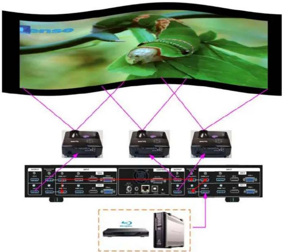
flowchart
graph TD
    A["Central Insect Larva"] --> B["SYNTS"]
    A --> C["SYNTS"]
    A --> D["SYNTS-1"]
    B --> E["OUTPUT"]
    C --> F["OUTPUT"]
    D --> G["OUTPUT"]
    E --> H["Computer"]
    F --> I["Computer"]
    G --> J["Computer"]
Only the input signal from HDMI-1/HDMI-3 input port can be looped out.
Input signal can be connected to HDMI-1/HDMI-3 input port and looped out to next processing module or unit.
If controlled by IR remote controller, please install two IR extender at different location for easy individual access by remote controller. Each GeoBox needs one IR extender.
User can setup M800 through Ethernet. Please change IP address in each M800 so that user can setup each unit separately through WebGui or Gwarp3 PC tool.
Select input port and set GeoBox output resolution to be the same as projector native resolution.
7.4. Projector settings
- Reset projector to default setting.
➢ Disable dynamic color adjustment and DLP Brilliant color adjustment.
➢ Disable Auto Keystone function.
Select a Display Mode with 2.2 gamma curve will reduce the color difference in overlap area. If necessary, please choose a Display Mode with the best result.
Use projector internal color adjusting function to adjustment the color variation among projectors before implement edge blending.
➢ Install projectors at a place with image size that can cover required image area and with minimized keystone to get the best video quality.
7.5. GeoBox Settings
- Reset GeoBox to default setting.
▶ Select input port.
Select output resolution to be the same as projector native display resolution.
➢ Check input/output LED indicators and make sure to have correction system connection.
➢ Disable [Frame Sync] function to eliminate Source re-search in the projector while executing GeoBox system setup through [Options]→ [Setting]→ [Frame Sync]→ [Disable].
If control by Ethernet, please set different IP address in each M800 (under Options→ Setting → Network menu).
7.6. Geometry alignment
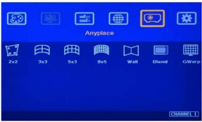
text_image
Anyplace 2x2 3x3 5x3 9x5 Wall Blend GWarp CHANNEL 1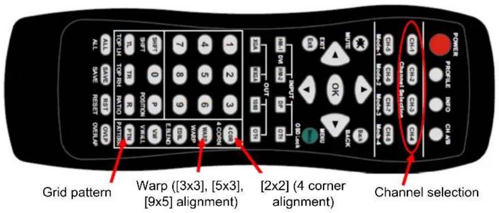
text_image
Grid pattern Warp ([3x3], [5x3], [9x5] alignment) [2x2] (4 corner alignment) Channel selection POWER PROFILE INFO CH AB UNIT MUTE OUT XQA MEDIA 1 2 3 4 5 6 7 8 9 10 11 DM INR3 DP QRI OUTPUT SHEI OBI ORI CH-1 CH-2 CH-3 CH-4 MAN-1 MAN-2 MAN-3 MAN-4 CH-3 CH-4 CH-7 CH-8 CH-1 Channel Selection CH-2 Channel Selection CH-3 Channel Selection CH-4 Channel Selection CH-1 Channel Selection CH-2 Channel Selection CH-3 Channel Selection CH-4 Channel Selection CH-1 Channel Selection CH-2 Channel Selection CH-3 Channel Selection CH-4 Channel Selection CH-1 Channel Selection CH-2 Channel Selection CH-3 Channel Selection CH-4 Channel Selection CH-1 Channel Selection CH-2 Channel Selection CH-3 Channel Selection CH-4 Channel Selection CH-5 Channel Selection CH-6 Channel Selection CH-7 Channel Selection CH-8 Channel Selection CH-9 Channel Selection CH-10 Channel Selection CH-11 Channel Selection CH-12 Channel Selection CH-13 Channel Selection CH-14 Channel Selection CH-15 Channel Selection CH-16 Channel Selection CH-17 Channel Selection CH-18 Channel Selection CH-19 Channel Selection CH-20 Channel Selection CH-21 Channel Selection CH-22 Channel Selection CH-23 Channel Selection CH-24 Channel Selection CH-25 Channel Selection CH-26 Channel Selection CH-27 Channel Selection CH-28 Channel Selection CH-29 Channel Selection CH-30 Channel Selection CH-31 Channel Selection CH-32 Channel Selection CH-33 Channel Selection CH-34 Channel Selection CH-35 Channel Selection CH-36 Channel Selection CH-37 Channel Selection CH-38 Channel Selection CH-39 Channel Selection CH-40 Channel Selection CH-41 Channel Selection CH-42 Channel Selection CH-43 Channel Selection CH-44 Channel Selection CH-45 Channel Selection CH-46 Channel Selection CH-47 Channel Selection CH-48 Channel Selection CH-49 Channel Selection CH-50 Channel SelectionUser can install IR extender receiver separately near each projector for easy GeoBox operation. If multiple units of GeoBox are used and IR receivers are put together, please set [Box ID] for each GeoBox so that user can control each M800 separately through [85x] command. Press number keys in Remote Controller following OSD menu for the control of multiple GeoBox:
- 850: will activate all GeoBox. User can execute simultaneous control for all GeoBox
- 851: activate only ID #1 GeoBox for further control.
- 852: activate only ID#2 GeoBox for further control.
Use [Pattern] & channel selection keys to show grid patterns in all projectors. Press [Pattern] key again will change grid color. To set two different pattern colors in adjacent projectors will be more convenient during geometry alignment.
If user finds the grid size between adjacent projectors is different. Some possibilities:
- The projection image sizes between two projectors are different (Zoom setting or projection distance is different).
- Output resolution settings in different GeoBox are not the same.
- Projector aspect ratio setting is different or not set at full screen display.
- GeoBox is set at [Original AR] under the menu of [Image Properties]→ [Scaling] menu.
Please follow the sequence [2x2][3x3][5x3][9x5] to do geometry alignment to ensure entire image will have uniform scaling factor.
Apply [2X2 Corner] geometry alignment and draw the corners to expected locations. It doesn't matter to have some image inside the screen once it covers entire screen before 4 corner adjustment. [Warp] alignment will adjust the image position back to the required position.
If user doesn't execute VNS Excel calculation, please use [2x2] alignment and try to let all projectors have similar image size with the overlap area having the same grid number.
➢ Apply [3x3 Curved] geometry alignment to let 9 adjusting points be located at the required position including four corners, edge center points and center line position.
➢ Please use [5×3] & [9×5] for further geometry alignment and fine-tune. [9×5] warp function has Linearity Grid Line adjustment function for smooth the grid size on curved screen.
After finish the alignment, user can use [2x2] for complete image position fine tune. If user executes [3x3] alignment again after [9x5] alignment, [9x5] grid position will be reset and only keep [3x3] grid point information.
In ideal condition, all grids in edge blending area between two adjacent projectors should be aligned together.
After the above processes, if the grid pattern in edge blending area still can't stack together, user can reduce overlapped grids to change the control point positions in adjacent projectors and get more accurate geometry alignment result.
[Gwarp3] PC tool can provide 17x17 grid point adjustment with quicker geometry alignment.
➢ After finish geometry alignment, all grids should be matched together.
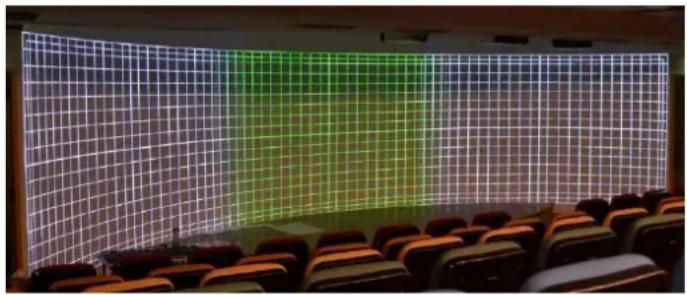
natural_image
Interior view of a modern auditorium with a large grid projection on the wall and rows of orange chairs in the foreground (no text or symbols visible)7.7. Video Wall settings
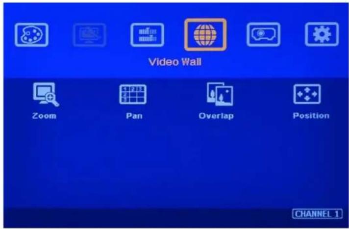
text_image
Video Wall Zoom Pan Overlap Position CHANNEL 1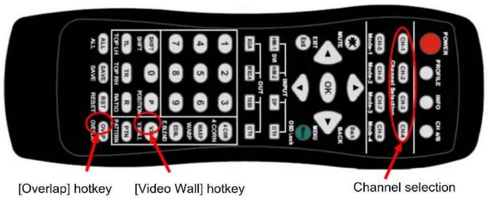
text_image
[Overlap] hotkey [Video Wall] hotkey Channel selectionClick [INFO] key to check if correct input and output timing is in the system. User needs to apply the same input/output timing as VNS Excel spread sheet calculation.
Example for [Video wall] settings for 3 projectors horizontal edge blending with two M800 cascaded:
- [Zoom]: set to H=3, V=1 in all channels. Each channel should be set separately.
- [Pan]: LH projector (1st): H=1, Center projector (2nd): H=2, RH projector (3rd): H=3. All projector Vertical PAN is the same: V=1.
- [Overlap]: select the correct edge and apply the value calculated from VNS Excel file
- LH projector: RH edge, Center projector: both RH/LH edges, RH projector: LH edge
- Below is overlap value calculated from VNS Excel under below condition:
Input: 3840*800, Output: 1280*800, Overlap pixels: 256, Projectors: 3
Horizontal Overlap value: Projector 1 RH edge=197, Projector 2 RH edge=98, LH edge=98, Projector 3 LH edge=197
Vertical values in all projectors are set with the same "V=0".
Video wall setting value
| Position of projector (H) | 1 | 2 | 3 | 4 |
| LH edge overlap value | 0.0 | 98 | 197 | x |
| RH edge overlap value | 197 | 98 | 0.0 | x |
| Position of projector (V) | 1 | 2 | 3 | 4 |
| Top edge overlap value | 0.0 | x | x | x |
| BTM edge overlap value | 0.0 | x | x | x |
For quad projector edge blending, user can apply still image, select correct edges and adjust [Overlap] value simultaneously and let the image in edge blending area comes closer till without double image. Two projectors shall have the same value (same cropping range). The difference shall not be over 2 pixels.
If user still sees some blurred image in edge blending area, please increase or decrease [Overlap] value in [Video Wall] setting to improve video quality.
Please note that projector has Thermal Drift issue (position shift due to different temperature). The image position in power ON stage may be different from the position after 15-20 minutes when the position is stable. Don't adjust image position during this period until it is stable.
7.8. [Edge Blend] setting
![GeoBox M801 - [Edge Blend] setting - 1](/content/2026/05/761429/images/4489529dfee7937b7630e58cac986312be277445a3cf5c119f86bd72655c93e1.jpg)
text_image
POWER PROFILE INFO CH-AB CH-1 CH-2 CH-3 CH-4 Channel Selection CH-5 CH-6 CH-7 CH-8 Mode-1 Mode-2 Mode-3 Mode-4 EXIT MUTE OK BACK RERU OUT XRA RENA SBB OTN 1 2 3 4 CORN 4 5 6 7 8 9 WASP ELEND SHIFT 0 P VW SHIFT POSITION V/VALL TL TR R PTN TOP LH TOP RH RATIO PATTERN ALL SAVE RESET OVER AP[Edge Blend] hotkey
Select correct Edge for the edge blending:
LH projector: RH edge, Center projector: RH & LH edge, RH projector: LH edge
RED and GREEN indicating lines will appear when increase edge blending pixels. The final overlap setting value will be the same as ac 256 in this example case.
User needs to adjust the color indicating lines to match together (green to green, red to red) and will see the final result.
![GeoBox M801 - [Edge Blend] setting - 2](/content/2026/05/761429/images/085af15d4a18e89dd104976a3db68f3395331a3ac9f2397625b99df47893cdda.jpg)
text_image
Anyplace 2x2 3x3 5x3 9x5 Wall Blend GWarp Edge Shift Gamma Offset Corner Color Mask Grid Change edge blending settings.7.9. Final Image quality fine-tune
If banding effect is visible in overlap area, please try below method:
-
GeoBox [Gamma] adjustment: Please try to adjust Gamma value in [Transition] & [Gain] menu and adjust [Shift] value to "-" to do color uplift in the edge of overlap region.
■ Projector adjustment: please try to change projector settings -
All projector should have the same setting.
- Select color profile with gamma 2.2 will get the best result.
- Check Display Mode. Usually Standard, sRGB modes will get better result.
- Disable projector Brilliant color or Dynamic color adjustment.
The video quality in overlap region is related to many factors. Please see more details in [Final Image quality fine-tune] section.
8. Save/Load System Settings
After finishing system settings, user can save the setting by [Save] hotkey in remote controller or OSD menu through [Menu]→ [Options]→ [Setting]→ [Profile]→ [Save]→ [Index 1-5]. [Save] Profile will take effect for two channels at the same time.
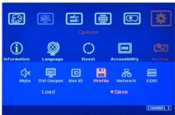
text_image
Options Information Language Reset Accessibility Setting Mute DVI Output Box ID Profile Network EDID Load Save CHANNEL 1
text_image
Options Information Language Reset Accessibility Setting Mute DVI Output Box ID Profile Network EDID •Index 1 Index 2 Index 3 Index 4 Index 5 CHANNEL 1User can recall (load) the setting through IR remote controller, WebGui or Gwarp3.
Five different display settings can be saved to [Profile]. The data stored in Profile include EDID setting, input source, output resolution, color settings and all user customized settings.
When user power off the system, M800 will save user setting without loss even the setting is not saved into Profile Index, unless someone to change it.
When system has been reset from OSD menu or update new Firmware, Profile data will be still kept inside M800.
Hotkeys for Profile [Save] and [Load]
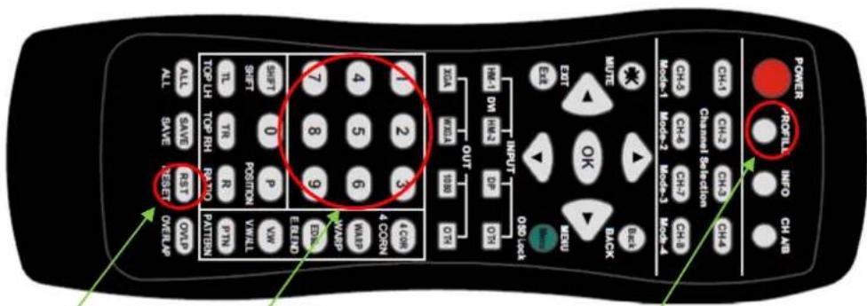
text_image
ALL SAVE RST OVERLAP SHIFT 0 P POSITION VAKLL PTN EREAD END TOP LH TOP RH RA TO PATTERN 1 2 3 4 CON 5 6 7 8 9 4 DM HR3 OUT DP DTS EASE EXIT MUTE INPUT OK MENU BACK Channel Selection Mode-1 Mode-2 Mode-3 Mode-4 CHA CH-3 CH-3 CH-B CH-4 CH-4 CH-4 MODE-1 MODE-2 MODE-3 MODE-4 ALL SAVE RST OVERLAP POWER ADFILL INFO CH ABPress [Save], then select [Index #] and press [Enter] to save settings. The setting will apply to all channels.
Number keys for Profile [Load]
Press [Profile] hotkey, then select number keys on the remote control (not through OSD direction keys) to [Load] user settings
9. Multiple unit applications
9.1. System connection in multiple unit edge blending
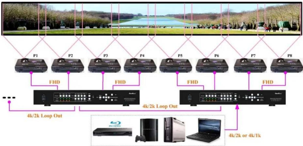
flowchart
graph TD
    A["Top Panel"] --> B["P1"]
    A --> C["P2"]
    A --> D["P3"]
    A --> E["P4"]
    A --> F["P5"]
    A --> G["P6"]
    A --> H["P7"]
    A --> I["P8"]
    B --> J["FHD"]
    C --> K["FHD"]
    D --> L["FHD"]
    E --> M["FHD"]
    F --> N["FHD"]
    G --> O["FHD"]
    H --> P["FHD"]
    I --> Q["FHD"]
    J --> R["4k/2k Loop Out"]
    K --> S["4k/2k Loop Out"]
    L --> T["4k/2k Loop Out"]
    M --> U["4k/2k Loop Out"]
    N --> V["4k/2k Loop Out"]
    O --> W["4k/2k Loop Out"]
    P --> X["4k/2k Loop Out"]
    Q --> Y["4k/2k Loop Out"]
    R --> Z["4k/2k or 4k/1k"]
    S --> AA["4k/2k or 4k/1k"]
    T --> AB["4k/2k or 4k/1k"]
    U --> AC["4k/2k or 4k/1k"]
    V --> AD["4k/2k or 4k/1k"]
Connect input signal to M800 one of the HDMI 1/3/5/7 input port and looped out to next processing channel. No special sequence is required.
In big scale display application, no limitation in the number of M800. The key point is that the system resolution needs to meet the requirement.
In multi-unit application, only HDMI-1/3/5/7 signal can be cascaded through internal HDMI splitter. If user wants to do edge blending with other input ports, please add video distributor at the front end and feeds the signal to all M800 processing modules. Each M800 has two processing modules.
➢ User can control M800 through Ethernet, USB or remote controller.
IF GeoBox is installed in control room, Ethernet control through WiFi will be the most convenient. Notebook, mobile phone and Pad can execute GeoBox setup through WiFi.
User can set individual Box ID and IP address for easy independent control of each GeoBox.
Select input port and set GeoBox output resolution to be the same as projector native resolution.
User needs to apply a signal source while executing video wall [Overlap] value setting. Signal source resolution should be the same as VNS Excel calculation. To apply 1080p or 4k signal is recommended. After system setup, user can use any input resolution.
➢ Press [INFO] hotkey to check if the final in/out timings are the same as expected.
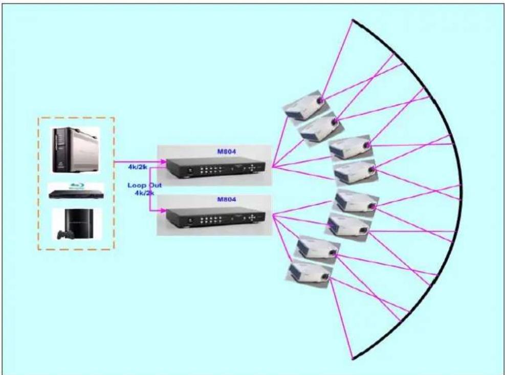
flowchart
graph TD
    A["Device 1"] -->|4k/2k| B["M804"]
    C["Device 2"] -->|4k/2k| B
    D["Device 3"] -->|4k/2k| B
    E["Device 4"] -->|4k/2k| B
    B --> F["Output"]
    style A fill:#f9f,stroke:#333
    style C fill:#f9f,stroke:#333
    style D fill:#f9f,stroke:#333
    style E fill:#f9f,stroke:#333
    style F fill:#ccf,stroke:#333
Usually, one 4k signal source can be applied for up to 20 meters screen through 2x M800 & 8x projectors. If bigger screen is required, user can apply multiple signal sources through multiple synchronized media player or multiple output display card to achieve higher system resolution.
9.2. Content overlap setting issue
If the system is larger than 20m, usually, multiple 4k signal source is required to get good enough video resolution. Below are some important points:
User needs to split the content into different sections and each section is played back by one PC or media player.
These PC or media player needs to be synchronized.
GeoBox can crop the right overlap pixel inside one content for each projector but not for the pixel between two independent contents.
The Overlap content between two independent signal sources shall be handles through below methods:
- To set Overlap image through PC display card. In this case, the overlap cropping issue in this section will be handled by PC.
- To cut the content with same content in overlap section for edge blending. The pixel size shall be larger than Overlap region and GeoBox can crop the right pixel for edge blending. User can use synchronized media player (such as BrightSign) or low-cost multiple output display card from PC.
- PC display card should be able to set overlap pixel up to 25% of the output resolution among the outputs. User can use similar function cards as Matrox TripleHead 2 Go, ATI Display Group, NVidia SLI Surround or NVidia Mosaic mode.
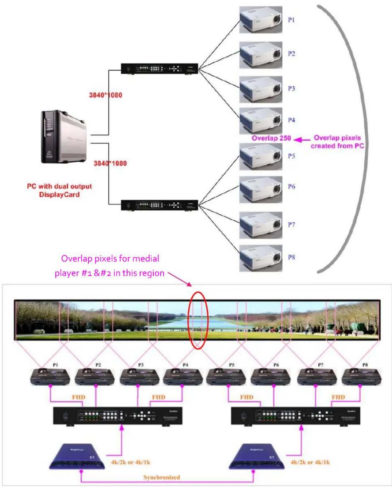
flowchart
graph TD
    A["PC with dual output DisplayCard"] -->|3840*1080| B["Computer"]
    A -->|3840*1080| C["Computer"]
    B --> D["P1"]
    B --> E["P2"]
    B --> F["P3"]
    B --> G["P4"]
    B --> H["Overlap 250"]
    B --> I["P5"]
    B --> J["P6"]
    B --> K["P7"]
    B --> L["P8"]
    C --> M["Overlap pixels for medial player #1 & #2 in this region"]
    M --> N["P1"]
    M --> O["P2"]
    M --> P["P3"]
    M --> Q["P4"]
    M --> R["P5"]
    M --> S["P6"]
    M --> T["P7"]
    M --> U["P8"]
    N --> V["FHD"]
    O --> W["FHD"]
    P --> X["FHD"]
    Q --> Y["FHD"]
    R --> Z["FHD"]
    S --> AA["FHD"]
    T --> AB["FHD"]
    U --> AC["Synchronized"]
Signal sources output two independent images with redundant data in overlap region
Projectors project the image with the same overlapped content
natural_image
Scenic park view with a lake, green lawns, and trees along the banks (no visible text or symbols)
natural_image
Scenic outdoor park with green field, trees, and people walking (no visible text or symbols)
natural_image
Panoramic view of a park with green lawns, trees, and a lake under clear sky (no visible text or symbols)
natural_image
Panoramic view of a long, empty river with a wide green grassy field and people walking along the banks (no visible text or symbols)GeoBox execute Geometry alignment and crops the right pixel based on projector position to do edge blending
9.3. Convenient Setting and PC tools in multiple unit application
9.3.1. Setup by Remote Controller
If multiple units are used, user can set different [Box ID] (#1 - #99) or IP address in each Box for individual control. For IR control, the [Box ID] number range is #1 - #9.
√ When all M800 or IR extenders are installed together in the control range of single remote controller, user can do individual M800 control through below method.
- Press [ 851 ] · all the box OSD will be locked except ID #1. The LED light will be flashing in the locked unit and only ID #1 can be operated through OSD menu.
- Press [ 853 ] · all the box OSD will be locked except ID #3. The LED light will be flashing in the locked unit and only ID #3 can be operated.
- Press [ 850 ] · all the box OSD will be unlocked and can be operated through remote controller at the same time.
9.3.2. Setup by Ethernet
User can connect all M800 in one Ethernet Router (WiFi Router or switch/hub) through LAN ports and set different Static IP address for each Box, then use WebGui virtual keys or Gwarp3 PC tool to control each M800 independently. Default IP address is 192.168.0.100. TCP Server port is 1266 and Telnet port is 23.
10. WebGui and Gwarp3 PC tool
User can connect all M800 in one Ethernet Router (WiFi Router or switch/hub) through LAN ports and set different Static IP address for each Box, then use WebGui virtual keys or Gwarp3 PC tool to control each M800 independently. Default IP address is 192.168.0.100. TCP Server port is 1266 and Telnet port is 23.
10.1. WebGui
WebGui is embedded inside M800. Once user connects M800 with PC through Ethernet, user can access WebGui and execute all operation similar to OSD menu through Virtual Keys and OSD Menu. No PC or appropriate software tool is required.
The connection can go through Ethernet router LAN port, WiFi Router or Crossover Cat 5/6 cable. User can set each M800 with different static IP address in the same domain, then open Google Chrome or Microsoft Explorer browser with IP address to access each unit of M800 for independent operation. There is no limitation in the number of M800 that can be controller at the same time.
User can turn on/off the system through WebGui or Gwarp3 and see the status through power indicator.

text_image
Virtual Key Video Wall Image System EDID UP MENU LEFT ENTER RIGHT DOWN CH-1 CH-2 XGA WXGA 1080 OTHER HDMI A HDMI B DP REBOOT POWER10.2. Gwarp3 PC Tool (will be updated)
Gwarp3 is a PC tool executed through PC. Please download this tool from VNS website. Once user opens Gwarp3 and connects with PC through Ethernet or USB, user can execute all operations through PC keyboard and mouse. User can also backup system setting in PC and restore or copy to other units.
➢ Firmware and MCU code update can be executed through Gwarp3. User can control multiple units at the same time through different IP address.
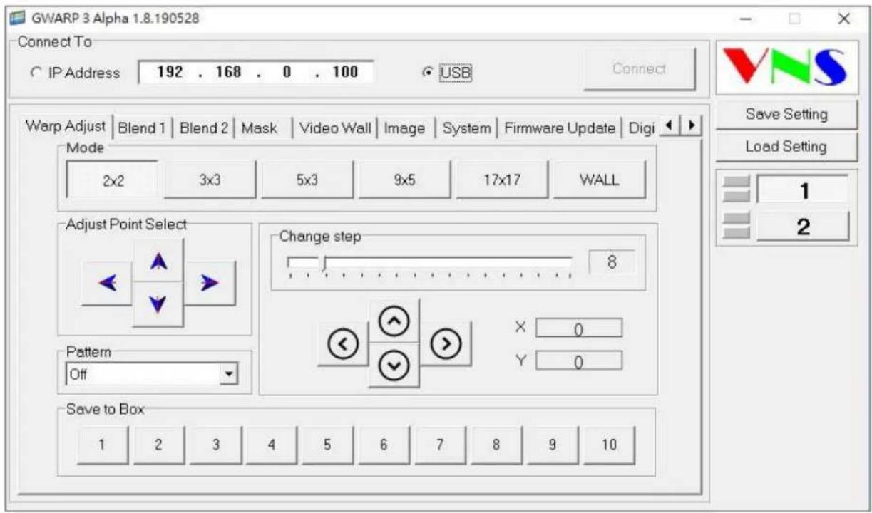
text_image
GWARP 3 Alpha 1.8.190528 Connect To C IP Address 192 . 168 . 0 . 100 USB Connect Warp Adjust Blend 1 Blend 2 Mask Video Wall Image System Firmware Update Digi Mode 2x2 3x3 5x3 9x5 17x17 WALL Adjust Point Select Change step 8 Pattern Off X 0 Y 0 Save to Box 1 2 3 4 5 6 7 8 9 10 VNS Save Setting Load Setting 1 211. Advanced applications and settings
11.1. Immersive display with multiple projectors
User can use multiple projectors to execute Corner Wall display with the images from different projectors. Below is the example for a display with 3 walls and one floor to build one immersive display.
11.1.1. Assumption
√ 3 walls display: W1=2m, W2=5m, W3=3m
√ Signal source: 3840x1080, GeoBox output resolution: 1920x1080
11.1.2. Usually, 5000 Lum projector can cover 3-4 meters image width. Four projectors are required to cover entire screen.
√ W1: one projector is enough
√ W2: require two projectors with edge blending to cover the space
√ W3: one projector is enough
√ Floor: 2-3 projectors is required.
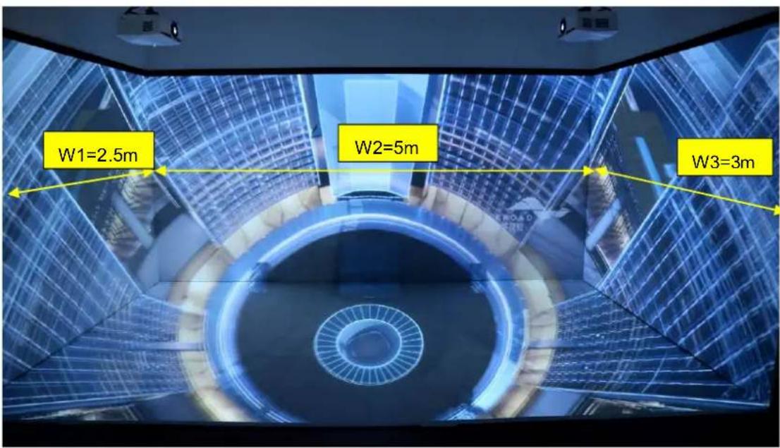
text_image
W1=2.5m W2=5m W3=3m11.1.3. Need to let all projectors with the same scaling factor to avoid image size difference among the walls.
√ Total screen dimensions: 2.5+5+3=10.5m
√ Total image width: 3840 pixels
√ Pixel density: 3840/10.5= 366 pixels/m
√ Assign image resolution for each wall to get the same scaling factor.
√ W1 (PJ1) =366*2.5= 914 pixels (Projector #1)
√ W2 (PJ2 & PJ3) = 366*5 = 1829 pixels (Projector #2 & #3)
√ W3 (PJ4) = 384*3 = 1097 pixels (Projector #4)
√ Based on the above data, if we convert the image location by coordinate, W1 is from 0 to 914, W2 is from 914 to 2743 (914+1829), W3 is from 2743 to 3840.
11.1.4. Video Wall settings:
User can set different Video Wall Zoom value for each projector separately. We assume to set Zoom at H=4, V=1 for all projectors.
√ The coordinates for the split image from video wall settings are 0-960-1920-2880-3840.
√ W1: Zoom: H=4, V=1, Pan: H=1, V=1
Overlap: 914-960=-46→ Right Edge = -46, Other Edge=0
√ W3: Zoom: H=4, V=1, Pan: H=3, V=1,
Overlap: 2880-2743= +137→ Left Edge = +137, Other Edge=0
√ W2: The image captured for W2 should be 1829. User needs to calculate Video Wall Overlap Pixel based on this resolution. If we set 320 overlap pixels, the overlap value in video wall is 86 pixels.
| Source resolution (H) | 1892 | Screen width | 5 | (m) |
| Source resolution (V) | 1080 | Screen height | 1.50 | (m) |
| Projector resolu. (H) | 1920 | Projector lumen | 5000 | (Lum) |
| Projector resolu. (V) | 1080 | Screen Aspect ratio | 3.33 | (required) |
| Overlap pixels (32 pixels per grid) | Overlap % | Recommended | ||
| Overlap pixel (H) | 320 | 16.7% | 20%~40% | |
| Overlap pixel (V) | 0 | 0.0% | 25%~40% | |
| Recommended overlap region: Min. 192 pixels or 50 cm width | ||||
| Qty of projector (H) | 2 | Throw ratio (Min) | 1.1 | |
| Qty of projector (V) | 1 | Throw ratio (Max) | 1.7 | |
| Final output resolution | ||||
| Horizontal resolution | 3520 | * Please apply Overlap pixels with 32x because internal grid size for geometry adjustment is based 32x32 for each grid. | ||
| Vertical resolution | 1056 | |||
| Extended pixel (H) | 86 | |||
| Extended pixel (V) | 0 | |||
| Final Image size (meter) | Final Illuminance Lux (Lum/m2) | Image size for each PJT | |||
| Width | 5.00 | PJT lumen | 5000 | Width (m) | 2.727 |
| Height | 1.53 | Final Illumin | 1195 | Height (m) | 1.534 |
| Overlap region size | Original aspect ratio | Projector throw distance | |||
| Horiz. (m) | 0.455 | Projector | 1.78 | Min (m) | Max (m) |
| Vertic. (m) | 0.000 | Final result | 3.26 | 3.00 | 4.64 |
Video wall setting value
* Illuminance: 1 Lux = 1 lumen/m2 = 0.0929 foot-candle
Luminance: 1 Lumen/m2/Steradian = 1Nit = 0.29186 Foot-Lambert
| Position of projector (H) | 1 | 2 | 3 | 4 | 5 | 6 | 7 | 8 | 9 | 10 |
| LH edge overlap value | 0.0 | 86.0 | x | x | x | x | x | x | x | x |
| RH edge overlap value | 86.0 | 0.0 | x | x | x | x | x | x | x | x |
Under this condition, the image cropped for PJ2 should be in the range from coordinate 914 to 1914.5 (914+1829/2+86=1914.5). The image for PJ3 should be in the range from coordinate 1742.5 (914+1829/2-86=1742.5) to 2743 (914+1829=2743).
√ PJ2 Video wall setting: Zoom: H=4, V=1, Pan: H=2, V=1. The standard coordinate after Zoom setting will be from 3840/4=960 to 960*2=1920, Overlap value will be:
Left Edge: 960-914=46, Right Edge: 1914.5-1920=-5.5 (actual -5 or -6)
√ PJ3 Video wall setting: Zoom: H=4, V=1, Pan: H=3, V=1. The standard coordinate after Zoom setting will be from 1920 (960*2=1920) to 2880 (960*3=2880), Overlap value will be: Left Edge: 1920-1742.5=177.5 (actual 177 or 178), Right Edge: 2743-2880=-137
√ After finishing video wall settings, user needs to set [Edge Blend] between PJ2 and PJ3 to finish complete system settings.
11.2. Portrait edge blending
When executing edge blending, the image will be stretched and the aspect ratio will be changed. In order to reduce aspect ratio change, user can execute portrait edge blending to increase image height. When execute image 90/270 degrees rotation, the input source resolution can be up to 4k/60Hz.
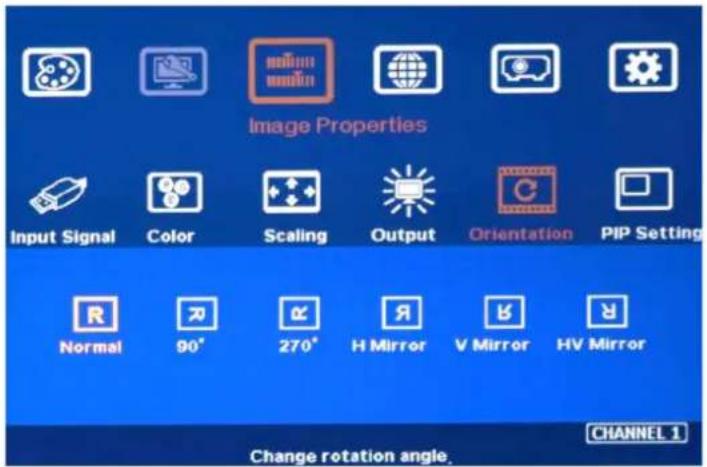
text_image
Image Properties Input Signal Color Scaling Output Orientation PIP Setting Normal 90° 270° H Mirror V Mirror HV Mirror Change rotation angle. CHANNEL 1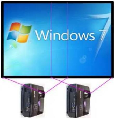
text_image
Windows 7Some projectors are not suitable to be installed at portrait location. Laser projector has high contrast ratio, no limitation in installation angle and accurate color and gamma curve. It is the best choice for edge blending application.
M800 can rotate source image before edge blending. It will be more convenient for user to connect with all kinds of conventional signals without the need to rotate the image in advance.
When apply portrait edge blending, the VNS Excel Spread Sheet calculation also needs to change the output resolution. If the projector is 1920x1200, then user needs to input Output Resolution (projector resolution) at 1200x1920.
The OSD menu will not follow rotated image. Video Wall setting direction will follow actual rotated image direction but not OSD direction.
All the function settings under [Anyplace] menu will follow OSD menu directions but not follow rotated image direction. The items include geometry alignment & edge blending.
Except for the directions, all the rest settings will be the same as normal display.
➢ Image rotation menu is under [Image Properties]
11.3. Flexible display
When edge blending is implemented, the image aspect ratio will be changed.
If the content has the same aspect ratio as the screen, the system can be setup to show no distortion image.
In order to reserve flexibility for different user environments, GeoBox allows user to set different display modes. Below is the example for 3 projector edge blending system.
- Case A: All-in-one: display one content across entire screen.
- Case B: 2+1: two projectors edge blended and one independent content display.
- Case C: 1+1+1: Each projector displays independent content.
➤ GeoBox setting for each case:
- Case A: it is normal edge blending setting. Save the setting to Index 1 under [Profile].
- Case B: user needs to reset all settings, select the input sources for discrete display and implement geometry alignment and edge blending only on two projectors with another one independently. Save the setting to Index 2.
- Case C: user needs to reset all settings, select the input sources for discrete display and implement geometry alignment to separate the images among all projectors without overlap. Save the setting to Index 3
User can store different settings into different profile Index and recall through remote controller, RS232 or Ethernet. No projector installation or settings is required.
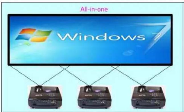
text_image
All-in-one Windows 7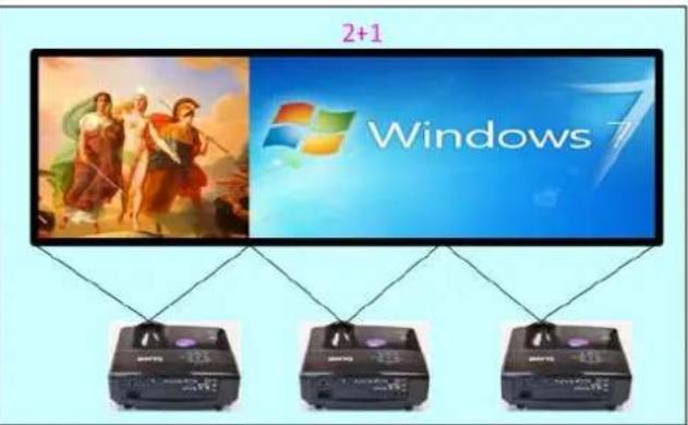
text_image
2+1 Windows 7 BATEL BATEL BATEL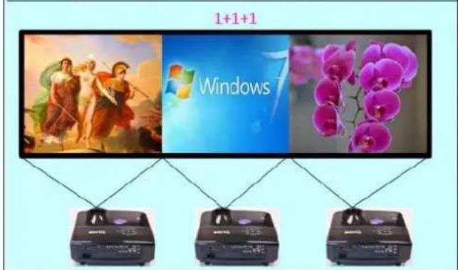
text_image
1+1+1 Windows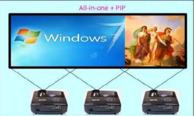
text_image
All-in-one + PIP Windows 711.4. Discrete content displayed in each projector
User can configure to show independent content in each projector. Below are the guidelines:
Signal source selection: only one HDMI input source can be selected as discrete display input source in one processing module. User can only select two HDMI input sourced for four discrete displays.
When execute discrete display, please reset [Video Wall] and Edge Blend] to default value.
➢ User need to use geometry alignment to let the images in projectors apart from each other.
If necessary, user can use [Overlap] function under [Video Wall] to adjust image aspect ratio. This function can also let the image in overlap area apart from each other without change geometry alignment. However, Video Wall [Zoom] setting and [Edge Blend] setting shall be reset to default. In this case, the maximum source resolution should be under 4k/2k @30Hz.
11.5. Complete system aspect ratio adjustment
User can change the aspect ratio of the image with black borders or to stretch the image in specific direction to compensate the aspect ratio difference between video wall and the content. The Maximum adjustment range is 1800 pixels in each edge. User can adjust [Overlap] value under [Video Wall] menu to change the cropping area and achieve aspect ratio change.
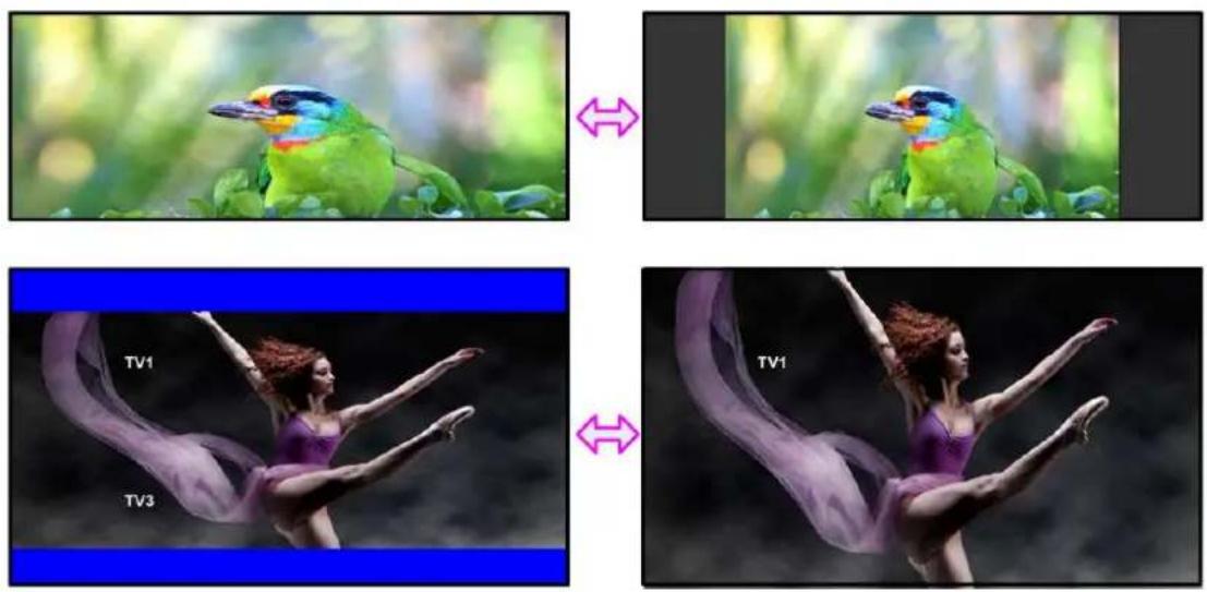
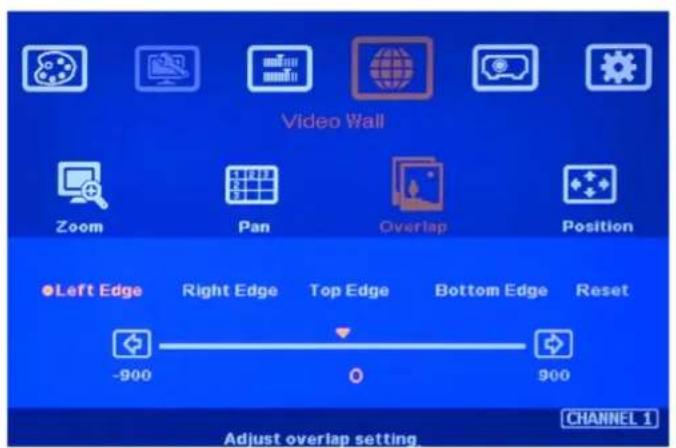
text_image
Video Wall Zoom Pan Overlap Position ●Left Edge Right Edge Top Edge Bottom Edge Reset -900 0 900 Adjust overlap setting CHANNEL 1Activate [Overlap] under [Video Wall] menu
- User can select the channel and the edge required for edge shift, then adjust Overlap value to see aspect ratio change.
- The image position shift range is +_1800 pixels in each edge.
If the Video Wall [Zoom] is set to H=1 & V=1, +-1800 pixels edge shift in RH and LH edges is only available under input signal up to 4k/2k @30Hz. Top Edge and Bottom edge are still functional when the input is 4k/60 with Zoom at H=1, V=1.
If Video Wall [Zoom] is set to H=2 & V=2 or above, user can execute up to +_1800 pixels overlap adjustment in all edges up to 4k/60 input resolution.
In multiple projector application, when user adjusts Top or Bottom Overlap value in one projector, user needs to adjust the same Overlap value in other projectors to let all projectors has the same scaling factor.
In two projector edge blending, when user adjusts horizontal aspect ratio, user needs to change Video wall Overlap value with the same number in both projectors until getting clear overlap image. In VNS Excel calculation, if user calculates original Overlap value with 3840 input resolution, after increase 500 pixels in both outside edges in projector 1 (RH edge) and projector 2 (LH Edge), user can shrink the image width. However, the overlap region will become blurred. User needs to re-calculate Overlap value by new input resolution 3840 + 500*2 = 4840 to get correct video wall Overlap value.
The adjustment range of 1800 pixels is calculated according to the signal source resolution. If the signal source is 4k/2k and the adjustment value is 1200 pixels, when switching to 1080p input signal, the adjustment value will be converted to 600 pixels automatically to maintain the same image position. If the input signal source is 1080p and the adjustment value is 1000 pixels, when switching to 4k/2k input signal, the adjustment value should be 2000 pixels. However due to the maximum adjustment value is only 1800 pixels, the final image will follow 1800 pixels but not 2000 pixels for 4k input. It means the image aspect ratio will not the same as 1080p input source.
12. Miscellaneous settings
12.1. Helpful tips for edge blending
➢ Image distortion and aspect ratio issues
If the content aspect ratio is different from the screen, it will cause image distortion. User can adjust aspect ratio through [Overlap] settings. However, you will have two choices:
- Full screen display but some content will be drawn to outside border and missing.
- Draw the image into screen and keep some blanking border at some borders.
If the signal is from PC, user can set customized EDID in GeoBox to let PC output expected output resolution. Some PC may not follow GeoBox EDID resolution setting and require customized output setting from display card.
M800 can support interlaced signal source (i.e. 1080i). However, if user rotates or flips the image, there will be no 3D motion adaptive de-interlaced function. User may see some small flick image while the input is still image. We strongly recommend applying progressive signal to avoid this kind of issue.
In the application with short throw ratio projector on curved screen, there will be big image distortion. User needs to apply big geometry alignment and degrade the video quality.
The optimized EDID resolution should be the final resolution after edge blending. For instance, if user uses three XGA projectors for edge blending with 250 overlapped pixels, then the best signal for this setup will be 1024*3-250*2=2572.
12.2. EDID Setting
Selective EDID setting for input source resolution is added into GeoBox. The settings will be applied to individual processing module on select input port. Each processing module needs to set EDID separately. For daisy chain connection, user only needs to set the EDID in the first input port connected with signal source. The purposes for EDID setting are as follows:
GeoBox can support big range of input signal timing—from XGA up to 4k/2k @60Hz. In order to get the best video performance, user needs to select the best input signal resolution.
Different display modes may show different final image aspect ratio. User can utilize different EDID setting to change signal source timing and get different output aspect ratio.
Use can select different EDID directly from OSD list or use [Customize] function to create Non-Vesa standard timing.
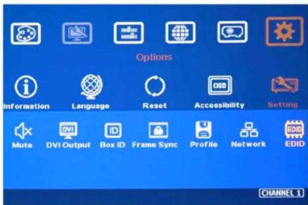
text_image
Options Information Language Reset Accessibility Setting Mute DVI Output Box ID Frame Sync Profile Network EDID CHANNEL 1- Activate EDID setting menu: [Options]→ [Setting]→ [EDID]
- Use IR remote controller to select desired EDID.
- After select EDID, signal source will auto-change the output timing setting.
- Press [INFO] key to check if the input and output timing are set correctly.
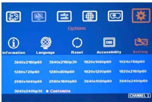
text_image
Options Information Language Reset Accessibility Setting 3840x2160p60 3840x2160p30 1920x1080p60 1024x768p60 1280x720p60 1280x800p60 1920x1200p60 1920x2160p60 2560x1440p60 2560x1600p60 3840x1080p60 3840x2400p60 3840x2400p30 ● Customize CHANNEL 1- User can also set EDID manually. The range for customized EDID will be from 1024x768 to 3840x2400.
- Horizontal resolution is in a step of 8 pixels and vertical resolution is in 1-pixel.
- After creating the EDID, PC or laptop may not output required timings due to hardware limitation or driver issue. User may need to do custom setting inside PC to get desired output resolution.
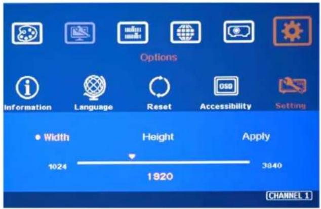
text_image
Options Information Language Reset Accessibility Setting Width Height Apply 1024 1820 3840 CHANNEL 112.3. HDMI vs. DVI Output Signal
HDMI digital signal is compatible with DVI signal. Most of display devices can support both digital signals. However, some old equipment may have less flexibility in digital input signal compatibility. In this case, user may need to select DVI output format for normal display in some devices.
HDMI signal embeds more signal information, such as audio and HDCP. Once some information is missing, it will also affect the display. It may cause intermittent or loss of image. Under this condition, user can try to set DVI output. The connection doesn't need to change.
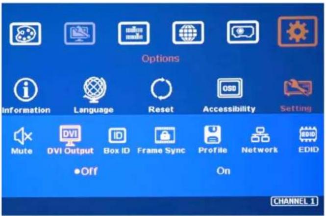
text_image
Options Information Language Reset Accessibility Setting Mute DVI Output Box ID Frame Sync Profile Network EDID •Off On CHANNEL 112.4. System Standby and Automatically Turn Off Output Signal
➢ [Options]→ [Accessibility]→[Standby Time]
If set [Standby Time] at 60, the system will get into Standby Mode after 60 seconds when no input signal is detected. The output signals from M800 will also be terminated at the same time. If M800 detects input signal again, it will automatically turn on the system.
If the projector can automatically turn off/on by detecting input signal, user can control signal source to execute entire system on/off control.
12.5. Change Background Color
When no signal input, the system will show blue color background with [Power Saving Mode]
message on the screen. User can change background color to black on the screen without text message on it through [Options]→ [Accessibility]→ Black Screen]→ [On]
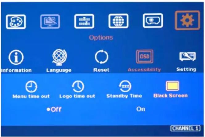
text_image
Options Information Language Reset OSD Accessibility Setting Menu time out Logo time out Standby Time Black Screen •Off On CHANNEL 112.6. Turn off splash screen Logo
Use can turn off splash screen Logo through [Options]→ [Accessibility]→ [Logo Time Out] and set the value at "0". Default setting is 10 seconds.
It will reduce the boot up time.
12.7. Limitation in Audio Output
If both HDMI and DP input are selected, then only HDMI audio will be selected as audio output.
13. Trouble Shooting
13.1. Front Panel LED indicators
User should see Input / Output LED lights in each channel. If no light illuminated in specific channel, please check Input / Output connecting cables, signal source & monitor in that channel.
If user sees continuous flashing in some channel LED, it means OSD may be locked. Please press [Menu] key for 5 seconds or press 850 number keys in remote controller to disable [OSD locked].
13.2. Intermittent or Loss of Input Signal
➢ Check the HDMI cable quality and make sure all cables are fitted correctly. 4k/60 signal requires high speed certified cables.
Cable length: Connecting cable length should be as short as possible. Replace a short cable to verify the possible root cause.
HDCP compliant issues: If the input source or the monitors are not HDCP compliant, it is possible to stop M800 from negotiating HDCP link and show intermittent, abnormal or no image. Please check HDCP condition in signal source or display device.
➢ Resolution issues: check if signal source and connecting cables can provide source signal supported by M800.
DVI/HDMI signal compatibility: some display devices may only support HDMI or DVI video signal and execute wrong signal format detecting. The default output is HDMI. User can change output with DVI format through [Options]→ [Setting]→ [DVI]→ [On].
Usually, to swap with different cable, output channel, signal source and projector can verify the root cause for the failure.
When it is possible to have signal compatibility issue, user can add one HDMI splitter/switcher in the middle to change signal impedance. It may fix the issue.
During system settings, the output signal may be temporarily lost and cause projector researching input signal and the image disappears shortly. User can disable [Frame Sync] function to avoid this kind of effect (see section 2.12). After finishing system setup, user need to set [Frame Sync] at [Normal] position to get perfect synchronization in all output channels.
13.3. Video quality issues
Use the highest resolution and number of color bits (RGB 4:4:4) images allowed by M800 to be used as a signal source whenever possible.
There are a number of lower-quality AV players, the specification and actual output are difference, or because of the use of lower color sampling bits or poor image compression technology, resulting in lower quality or image is not smooth (LAG).
If the use of H.264/H.265 compressed files, please select a player with hardware decoding to get smooth video quality.
If the input signal is interlaced signal (interlaced-1080i), and the image is rotated or flipped, then the channel will have no [3D Motion adaptive de-interlaced] processing function. If user applies static image source, the output video will have a slight jitter phenomenon. The processing channel quality will be reduced. Use a progressive signal source setting (1080p/2160p) whenever possible.
➢ Please press [INFO] shortcut key to check the input/output signal settings.
13.4. Image position shift after installation
The position shift in the projector will be enlarged to more than 10x due to projection distance. One mm image shift inside projector may appear 1cm image shift on the screen. User will clearly see blurred effect on overlap region in edge blending setup.
There will be some image position shift after system setup. The main reasons are as follows:
- Thermal drift due to projector internal temperature change. When power on the projector, the temperature is lower. After 20-30 minutes, the image position shift may be up to 5-10mm. It will be more obvious in overlap region. Different projector will have different thermal drift range.
- Stability of mounting system.
- Projector structure change after installation due to weight and thermal effect.
- Cable connection and cause weight balance issue.
- Change lamp
- Earth quake or caused by human reasons.
The first projector image position calibration should be done within one month after installation. The second calibration may be required after 3 months, then every 6 months or once a year.
If user finds big position shift and doesn't know the real issue. Please follow below procedures to confirm the issue is from GeoBox or not.
- Turn off GeoBox and open projector internal test pattern.
- Mark the corner positions of the projector image.
- Check projector image shift condition after some time with GeoBox in OFF condition.
- User will clearly identify that the position shift is from GeoBox or not after this procedure.
- GeoBox is digital processor and will not change image position only for few pixels.
13.5. System crash and malfunction
➢ After FW update, please reset the system through a pin inserting to reset hole on the back panel for 5 seconds to avoid abnormal settings inside the system.
When the input source is 4:4:4 PC graphics signal, only [Brightness], [Contrast] and [Sharpness] three items under [Picture] menu can be executed. If the input is 4:2:2 video source, all the items are functional.
When implement [Corner Wall] alignment, other geometry functions will be not functional.
Remote controller may be interfered by environment and can't be smoothly operation.
Gwarp settings: If no Gwarp3 data in UserMap and user click UserMap key, the image will disappear. Please select [2x2] geometry alignment key to recover OSD menu.
13.6. Synchronization issue in the outputs
The input refresh rate should be the same as output refresh rate so that the system can implement Frame Lock to synchronize all the outputs. If the input source is 50Hz with 60Hz output, it is possible to see some lag among the displays.
➢ [Frame Sync] menu is under system [Setting] menu. There are three sub-menu:
- [Normal] (Frame Locked): when user uses multiple units or M800, we propose to set at [Normal] to let all output synchronized together. The sync time will be longest. When you reset system or adjust video wall settings, you may see projector re-searching the input source.
- [Fast] (Phase lock): time to sync the input source will be fast than [Normal]. However, due to projector still needs to re-search input signal, the total signal change time including projector re-searching will be very similar. You can select [Fast] if you use single G802. All the rest conditions, we propose to take [Normal] frame lock.
- [Disable] (Free-Run mode): Once [Disable] is selected, when GeoBox changes input source or timing, the output will be still running without losing any signal. The projector will not search the input source again. There will be no loss signal when Reset or executing video wall settings. We propose user can set at [Disable] during system settings to save some time. After finishing system settings, user needs to switch back to [Normal]. Otherwise, it is possible to have some frame tear or not synchronized issues.
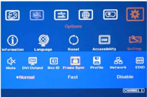
text_image
Options Information Language Reset Accessibility Setting Mute DVI Output Box ID Frame Sync Profile Network EDID •Normal Fast Disable CHANNEL 114. Technical support
User can send e-mail to sales@vnstw.com together with as much information as possible.
The following information is required for a swift response.
- Sink device (projector): type and model number
- Screen details or specific application details.
- GeoBox model No. and series No.
- Details of the signal source and the resolution.
- Press [Info] key to get System Information and send the data to us, including input/output timing and F/W version.
- The exact nature of the problem. Please be as detailed as possible.
- If possible, please attach the Pictures of the issue.
✿ Usually we will response within 24 hours (excluding weekends)
Please note that if the machine is sent back for repair, user needs to pay for the delivery cost.
15. Safety Precaution and Maintenance
15.1. Power Supply
Please connect electric power for all devices in the system from the same Power Distribution Box with correct grounding. Open the power after finishing system connection to reduce the risk for system damage from high floating voltage.
15.2. Working Environment
Please locate M800 in an environment free from dust, moisture and high temperature with good ventilation.
15.3. Warranty
This device is designed and tested to the highest standards and backed by two years' parts and labor warranty. Warranties are effective upon the first delivery date to the end customer and are non-transferable. Warranty period extension is available up to 5 years through paying extra charges.
15.4. Maintenance and Repair
Apart from what is detailed in User Guide, maintenance should be carried out by competent technician assigned by VNS. If M800 is physically damaged, it should be returned for repair using VNS RMA procedures. If the unit is opened by user, it will lose the right for warranty protection.
Specification
✧ Each box has 1-4 processing modules.
- M801: Single module processor
- M802: Dual module processor
- M803: Triple module processor
- M804: Quad module processor
✨ Each processing module includes:
- Input: 2x HDMI 2.0b, 1x DP1.2a and 1x VGA
- Output: 1x HDMI
- Loop output: 1x HDMI 2.0 for cascade.
◇ HDCP: HDMI V2.2/V1.4, DP: HDCP: V1.3
Max. input resolution: 4096x2160 60fps
Output: HDMI up to 2048x1080/60, output signal is RGB 4:4:4 progressive.
✿ New generation warp engine for geometry alignment up to 17x17 grid control points.
✿ Maximum geometry adjustment up to 1200 pixels in both H&V directions.
Edge blending at 4 edges up to H=1920 pixels, V=1200 pixels with independent R, G, B gamma correction.
✿ 9 regions black level uplift to compensate light leakage from projector optical system.
✿ Support Corner Wall adjustment in H&V at flexible location.
✿ Support Linearity Grid Line adjustment for quick H&V line position alignment.
✿ Embedded video wall function for image split, cropping and edge blend overlap pixel setting.
✿ Support non-VESA standard input timings for easy connection with various signal sources.
✨ Selectable output up to 2048*1080 60Hz.
Selectable grid pattern size from 8-120 pixels in H&V direction. Default is 32^*32 pixels.
✧ Selectable grid pattern color with optional transparency to see background image.
✿ Flexible aspect ratio adjustment in each edge up to +_ 1800 pixels position shift.
◇ Frame lock function to get perfect synchronized outputs in all channels.
✿ Frame rate conversion and 50Hz in/out function to eliminate image frame repeat.
- Three synchronization method: phase lock, frame lock & free-run modes.
✿ Free-run mode provides continuous signal to projector, no source searching required when timing change.
✿ 10-bit processor, 3:2/2:2 cadence, low angle smooth algorithm, high quality scaling engine.
✿ 4:4:4 Chroma sampling, 30 Color bits, 12-bit RGB gamma CLUT.
✿ Support sRGB & xvYCC color processing & 8/10/12-bit deep color.
✿ 3D motion adaptive de-interlace.
High Dynamic Range (HDR) support: SMPTE ST-2084, SMPTE ST-2086
❖ Individual color and white balance adjustment in each processing channel. - Individual 90/180/270 rotation, flip, cropping, scaling & color adjustment in each channel up to 4k/60 input.
✿ PIP/POP function with PIP image size from 320*180 up to 1920*1200 resolution with flexible position and selectable aspect ratio. This function is not available when the main image is 90/270 degrees rotation.
✨ Embedded HDMI audio outputs.
✨ Selectable and programmable EDID.
✿ ESD Protection: ±8kV (Air-gap discharge), ±4kV (Contact discharge)
Power supply: AC In: 100V-240V, DC Out: 12V 3A
Max. Power consumption: max. 28w (M804)
Working environment: 45°C, 10-90% RH
◇ Control: keypads, IR, RS232, USB, Ethernet
◇ System settings can be stored and backup.
◇ Dimensions: M801: 303mm*180mm*45mm, weight: 1.8kg M802-M804: 440mm*180mm*55mm Weight: 2.4kg-2.8kg
CE/FCC/RoHS/Reach Certified
✿ 2 Year Warranty, paid extension available up to 5 years.
Revision History
| Revision | Date Originator Comments | ||
| V1.0 2019 | 9-05-13 | Steve Wang | First version |
| V1.1 2019 | 9-05-19 | Steve Wang | Fixed typo |
| V1.2 2019 | 9-06-18 | Steve Wang | Fixed typo |