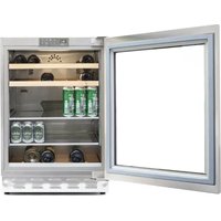
UCB601TGMO - Refrigerator Fhiaba - Free user manual and instructions
Find the device manual for free UCB601TGMO Fhiaba in PDF.


| Brand | Fhiaba |
| Model | UCB601TGMO |
| Product Type | Under Counter Refrigerator with Bottom Freezer |
| Total Net Capacity | 140 L (Refrigerator 100 L, Freezer 40 L) |
| Dimensions (H x W x D) | 83.5 x 59.5 x 57.0 cm |
| Weight | 55 kg |
| Energy Efficiency Class | D (EU 2019/2018) |
| Annual Energy Consumption | 180 kWh |
| Climate Class | SN-T (Subnormal to Tropical) |
| Noise Level | 39 dB(A) |
| Power Supply | 220-240 V ~ 50 Hz |
| Refrigerant | R600a |
| Electronic Temperature Control | Yes, with digital display |
| Super Cool Function | Yes |
| Fast Freeze Function | Yes |
| Automatic Defrosting (Refrigerator) | Yes |
| Door Alarm | Yes |
| Child Lock | Yes |
| Interior Light | LED |
| Adjustable Shelves | Yes, 2 glass shelves |
| Freezer Compartment Drawers | 1 freezer drawer |
| Door Handle | Integrated or custom panel ready |
| Maintenance and Cleaning | Clean interior and door seals with mild detergent and soft cloth; vacuum condenser coils annually |
| Safety Features | Door alarm, child lock, overheat protection |
| Spare Parts Availability | Through authorized service centers |
| Repairability Index | 8.2/10 |
| User Manual Languages | EN, IT |
Frequently Asked Questions - UCB601TGMO Fhiaba
User questions about UCB601TGMO Fhiaba
0 question about this device. Answer the ones you know or ask your own.
Ask a new question about this device
Download the instructions for your Refrigerator in PDF format for free! Find your manual UCB601TGMO - Fhiaba and take your electronic device back in hand. On this page are published all the documents necessary for the use of your device. UCB601TGMO by Fhiaba.
USER MANUAL UCB601TGMO Fhiaba
Installation Guide and User Manual
1 INDICAZIONI IMPORTANTI PER LA SICUREZZA E PER L'AMBIENTE 4
2.1 Installazione
natural_image
Diagram showing two connected pipe fittings with a bulb, no text or symbols presentnatural_image
Simple line drawing of a horizontal panel with a plug and cable, no text or symbols presentnatural_image
Two-step diagram showing a pipe fitting connected to a connector, with no visible text or symbols.
Attenzione
natural_image
Illustration of hands using a power plug to install a wall socket (no text or symbols present)
Importante
natural_image
Line drawing of a double-door refrigerator with multiple shelves and doors open (no text or symbols)natural_image
Line drawing of a multi-tiered industrial oven or chamber with doors and control panel (no text or labels)
natural_image
Pure electrical circuit lines without any symbols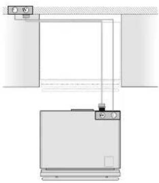
natural_image
Pure electrical circuit lines without any symbolsnatural_image
Line drawing of a refrigerator with two blue arrows pointing to the top panel (no text or symbols present)natural_image
Diagram showing a door with a small inset view of a wooden post and a tool, no text or symbols present.natural_image
Diagram showing a door frame with a magnified inset illustrating the angle of rotation (no text or symbols)
| ∅ 30 mm | CODICE MANIGLIA | ||
| H08 H07 H05 | |||
| Lunghezza A | 794 mm(31 1/4") | 644 mm(25 3/8") | 494 mm(19 5/8") |
| Interasse X | 480 mm(18 7/8") | 490 mm(19 1/4") | 340 mm(13 3/8") |
| Serie 90 75 | 60 | ||
| ∅ 18 mm | CODICE MANIGLIA | ||
| HC8 HC7 HC5 | |||
| Lunghezza A | 794 mm(31 1/4") | 644 mm(25 3/8") | 494 mm(19 5/8") |
| Interasse X | 776 mm(30 1/2") | 626 mm(24 5/8") | 476 mm(18 3/4") |
| Serie 90 75 | 60 | ||
natural_image
Architectural diagram showing a window frame and wall-mounted door assembly with directional arrows indicating movement (no text or symbols)natural_image
Line drawing of a window frame with a hand holding a cable, showing the process of adjustment (no text or symbols present)natural_image
Line drawing of a window frame with a hand holding a screwdriver, showing two views (top and side) without any text or symbols.natural_image
Line drawing of a cabinet with an open door, no text or symbols presentnatural_image
Illustration of hands installing or adjusting a rectangular panel with a screwdriver (no text or symbols)natural_image
Line drawing of an open refrigerator with internal components, showing exterior and interior views (no text or symbols)natural_image
Diagram showing a screw being inserted into a pipe with directional arrows indicating motion (no text or symbols)8.1 Ventilazione

| A | 200mm (7 7/8") |
| B | 60mm (2 3)/8 |
natural_image
Technical line drawing of a mechanical assembly with mounting brackets and structural components (no text or symbols)natural_image
Technical line drawing of an open refrigerator with cooling unit doors and internal shelves, showing airflow direction (no text or symbols)natural_image
Line drawing of a refrigerator with open door and side compartments (no text or symbols)BEVERAGE:
natural_image
Line drawing of a double-bowel kitchen cabinet with multiple shelves and an open door (no text or symbols)CANTINA VINI 2 TEMPERATURE:
natural_image
Line drawing of a double-door refrigerator with multiple compartments and one door open (no text or symbols)CANTINA VINI 1 TEMPERATURA:
natural_image
Line drawing of a multi-tiered industrial cabinet or oven unit (no text or symbols visible)CASSETTONI TRIMODE:
Beverage Center 2 temperature Cantina vini 2 temperature

12.2 Composizione
Beverage Center 2 temperature Cantina Vini 2 temperature
Chill and serve

Chill and Serve attivo
1
natural_image
Diagram of a mechanical component with directional arrows indicating rotation or flow (no text or symbols)5
6
1 IMPORTANT DIRECTIONS FOR SAFETY AND THE ENVIRONMENT 42
1.1 For your safety 42
1.2 Important information when using the appliance 42
1.3 Caring for the environment 43
1.4 Cleaning, sanitisation and maintenance of the ice and/or water dispenser (if present) 43
2 INSTALLATION 43
2.1 Installation 43
2.2 Connection to the water system (if present) 43
2.3 Connection to the electrical power supply 44
2.4 Refrigerant 44
3 BEFORE STARTING 44
3.1 Know your Fhiaba 44
3.2 Child safety 45
4 TECHNICAL REQUIREMENTS 46
4.1 Installation Opening Requirements: Beverage and Wine Cellar Indoor 46
4.2 Installation Opening Requirements: TriMode drawers Indoor 47
4.3 Installation Opening Requirements: Beverage and Wine Cellar Outdoor 48
4.4 Installation Opening Requirements: TriMode drawers Outdoor 49
5 PREPARING THE INSTALLATION 50
5.1 Transport to installation site and unpacking 50
5.2 Electrical and Water connection 50
5.3 Anti-Tip Bracket 51
6 DOOR SWING 52
6.1 Change the opening direction of the door (Indoor models) 52
6.2 Change the opening direction of the door (Outdoor models) 53
7 PANEL MOUNTING 54
7.1 Integrated Panel Dimensions 54
7.2 Mounting the handles 56
7.3 Integrated Panel Installation 57
7.4 Mounting panel to the door 58
7.5 Mounting panels to the drawers 60
8 VENTILATION 61
8.1 Ventilation 61
9 DOOR SWING 62
9.1 Door swing 62
10 POST INSTALLATION 62
10.1 Post installation checklist 61
11 FEATURES 63
11.1 Main components 63
12 GETTING STARTED 64
12.1 Main control panel 64
12.2 Layout 65
12.3 Functions 65
12.4 Keypad 65
13 SWITCHING ON/OFF 66
13.1 Switching ON/OFF 66
14 ADJUSTMENTS 66
14.1 How to adjust the temperature to meet user requirements 66
15 EVENT NOTIFICATIONS 67
15.1 Event notifications 67
15.2 Wine cellar event notifications 68
16 SETTINGS AND SPECIAL FUNCTIONS 69
16.1 Special functions 69
16.2 User menus 69
17 LIGHTING 72
17.1 Lighting 72
18 GENERAL DIRECTIONS 72
18.1 General directions 72
19 CARE AND CLEANING 73
19.1 Care and Cleaning 73
19.2 Condenser cleaning 73
19.3 Internal cleaning 73
1.1 For your safety
If this appliance is replacing an existing appliance which must be removed or disposed of, make sure that it does not become a dangerous trap for children by cutting its power supply cable and rendering it impossible to close the door. Use the same caution at the end of the lifespan of the new appliance.
The appliance is not designed to operate with external timers or with remote-control systems.
This appliance is designed to refrigerate beverages and foods and is intended for domestic use.
This appliance is for refrigeration and conservation of fresh and frozen foods in the home. Every other use is considered inappropriate.
The appliance must be installed by following the instructions in the Installation Guide, particular care should be taken not to obstruct the vent openings of the appliance and of the built-in units.
The appliance features a concentrated lighting system with LED lamps. Do not stare into these lamps when they are on to avoid possible eyesight damage.
This warning is also contained on the label attached to the inside of the refrigerator door.
When the freezer is functioning do not touch the inner surfaces in stainless steel with wet or damp hands, since skin may stick to the very cold surfaces.
Do not use any type of electrical equipment inside of the food conservation compartments.
When positioning the shelves, do not place fingers in the shelf slide guides.
Do not place flammable liquid containers nearby the equipment.
Never attempt to extinguish a flame/fire with water: turn off the appliance and cover the flame with a fireproof blanket.
Do not position containers of flammable liquids near the appliance.
Completely switch off the appliance and unplug the power supply cable during cleaning operations. If the plug is not easily reached, it is a good idea to turn off the breaker or remove the fuse that controls the socket that the appliance is connected to.
The packaging parts can be dangerous for children: do not allow children to play with the plastic bags, plastic film or Styrofoam.
Any repairs must be performed by a qualified Fhiaba Service technician.
This appliance is not intended for use by persons (including children) with reduced physical, sensory or lack of experience and knowledge unless they have been given supervision or instruction con-
cerning use of the appliance by a person responsible for their safety. Children should be supervised to ensure that they do not play with the appliance.
Do not damage the appliance refrigerant circuit pipes.
Do not store explosive substances such as aerosol cans with a flammable propellant in this appliance.
If the power cord of this appliance is damaged, it must be replaced by the manufacturer, customer service or a similarly qualified person. Improper installations and repairs may put the user at considerable risk.
Repairs may be performed by the manufacturer, customer service or a similarly qualified person only.
Plug into a grounded 3 prong outlet.
Do not remove ground prong.
Do not use an adapter.
Do not use an extension cord.
Disconnect power to all units before servicing.
If the SUPPLY CORD is damaged, it must be replaced by the manufacturer, its service agent or similar qualified person in order to avoid a hazard.
Children should be supervised to ensure that they do not play with the appliance. children.
Do not modify this appliance.
Do not insert pointed metal objects (cutlery or utensils) into the slots in the appliance.
Do not touch (especially with wet hands) frozen products or 22 - PRECAUTIONS 914779600/A put them in your mouth directly.
Do not store inflammable, explosive or volatile substances.
Do not keep explosive substances, such as spray bottles with flammable propellants in the appliance.
Bottles containing strong alcoholic drinks must be tightly closed and stored vertically.
Organic compounds, acids and essential oils can corrode the seals and plastic surfaces if left in contact with them for extended periods.
Turn off the appliance and unplug it from the mains before cleaning or maintenance.
Do not pull the cable to unplug the appliance.
1.2 Important information when using the appliance
Cleaning and maintenance that should be performed by the user must not be carried out by unsupervised children.
Never use electrical appliances inside the appliance (e.g. heater, electric ice maker, etc.). Explosion hazard!
Never defrost or clean the appliance with a steam cleaner! The steam may penetrate electrical parts and cause a short-circuit. Risk of electric shock!
Do not use pointed and sharp-edged implements to remove frost or layers of ice. You could damage the refrigerant tubes. Leaking refrigerant may cause eye injuries or ignite.
Take care that no objects are stuck in the doors.
Do not store products which contain flammable propellants (e.g. spray cans) or explosive substances in the appliance.
Do not stand on or lean heavily against base of appliance, drawers or doors, etc.
Before cleaning the appliance, pull out the power cord plug or switch off the fuse. Do not pull out the power cord plug by tugging on the power cord.
Store high-percentage alcohol tightly closed and standing up.
Keep plastic parts and the door seal free of oil and grease. Otherwise, parts and door seal will become porous.
Never cover or block the ventilation openings for the appliance. injury
According to current regulations, children between 3 and 8 years of age can take or load food from the appliance, but it is highly discouraged to allow children under 8 years of age to perform these operations and in general to use the appliance.
Keep children under the age of eight at a safe distance unless they are constantly supervised and make sure that they do not play with the appliance.
Do not use mechanical, electrical, chemical devices other than those recommended by the manufacturer to speed up the defrosting process.
Do not damage the cooling circuit (if it can be accessed).
Do not use electrical appliances inside food storage compartments unless these are of the type recommended by the manufacturer.
Explosion hazard!
In the event of damage to the cooling circuit, avoid the use of naked flames and ventilate the area properly.
Do not use the appliance or parts of it in ways other than those specified in this manual.
Opening the door for long periods can cause the temperature in the appliance compartments to rise considerably.
Clean surfaces that may come into contact with food and accessible drainage systems regularly.
Store raw meat and fish in suitable containers in the refrigerator, so that it does not come into contact with other food or drip on it.
If the appliance is left empty for long periods of time, switch it off, thaw it, clean it, dry it and leave the door open to prevent the development of mould inside.
Never rest sharp metal objects such as knives, forks, spoons and lids on the appliance during use.
Do not use abrasive or corrosive detergents (e.g. scouring powders, stain removers and metallic sponges) on glass parts.
Do not sit on the appliance.
Do not sit or lean on the door or any open drawers.
Do not prize on the door or handle to move the appliance.
Do not use electrical appliances (e.g. hair dryers) or sprays for defrosting, the plastic parts could be damaged.
Do not use the appliance to cool rooms for any reason.
Always unplug the appliance in the event of a fault or when performing cleaning or maintenance.
Do not keep liquids in tins or glass containers in the freezer.
Do not place heavy objects on the top of the appliance.
Symbols used in the Manual:

Note
tips for correct use of the appliance

Important
Warnings to prevent damage to the device

Attention
Warnings to prevent injury to persons
1.3 Caring for the environment


This appliance conforms to the WEEE European directive (2012/19/EU) and must be disposed of separately from other waste at the end of its service life.
The appliance does not contain substances in quantities sufficient to be considered hazardous to health and the environment, in accordance with current European directives.
Pay special attention to correct disposal procedure for all the packaging materials.

Power voltage
Danger of electrocution
Disconnect the mains power supply. Unplug the appliance.
The appliance must not be disposed of with urban waste. Contact local waste disposal centres for on how to dispose of recyclable waste.
To dispose of the appliance: Cut the power cable and remove it.
Prior to disposal, cut the power supply cord and make it impossible to close the door.
During disposal, avoid damage to the refrigeration circuit.
The appliance does not contain hazardous substances for the atmospheric ozone layer, neither in the refrigeration circuit nor in the insulation.
Our appliances are packaged in non-polluting and recyclable materials.
Deliver the packing materials to the appropriate recycling centre.

Plastic packaging
Danger of suffocation
Do not leave the packaging or any part of it unattended.
Do not let children play with the plastic bags.
1.4 Cleaning, sanitization and maintenance of the ice and/or water dispenser (if present)
Any work on the appliance must be carried out by a qualified technician or authorized After-Sales Service.

Warning
To avoid contamination of food, please respect the following instructions:
Opening the door for long periods can cause a significant increase of the temperature in the compartments of the appliance.
Clean regularly surfaces that can come in contact with food and accessible drainage systems.
Clean water tanks if they have not been used for 48 h; flush the water system connected to a water supply if water has not been drawn for 5 days.
Store raw meat and fish in suitable containers in the refrigerator, so that it is not in contact with or drip onto other food.
Two-star frozen-food compartments are suitable for storing pre-frozen food, storing or making icecream and making ice cubes.
One-, two- and three-star compartments are not suitable for the freezing of fresh food.
If the refrigerating appliance is left empty for long periods, switch off, defrost, clean, dry, and leave the door open to prevent mould developing within the appliance.
1.5 Informations for control bodies
For EcoDesign checks, the installation and preparation of the appliance must comply with EN 62552 standard.
Ventilation requirements, dimensions and minimum space from the rear wall are indicated in the "Installation" chapter of this manual.
Contact the manufacturer for more information.
1.6 To save energy
Correct use of the appliance, correct packaging of foodstuffs, a constant temperature and food hygiene have effects on the quality of storage.
Reduce the number of times that the doors are opened and the length of time they remain open to prevent the compartments from heating up excessively.
Clean the condenser (if it can be accessed) at the rear of the appliance periodically to prevent the appliance from losing efficiency.
Defrost frozen food in the refrigerator compartment in order to make use of the cold stored in the frozen foods.
1.7 Environmental labelling
PACKAGING MATERIAL KEY
| Material | Abbreviation | Numbering | |
| A | Low-density polyethylene | LLDPE | 4 |
| B | Uncorrugated cardboard | PAP | 21 |
| C | Polystyrene | PS 6 | |
| D | Wood | FOR | 50 |
| E | Iron | FE 40 | |
| F | Polyvinyl chloride | PVC | 3 |
| G | Polypropylene terephthalate | PET | 1 |
| H | Corrugated cardboard | PAP | 20 |


natural_image
Simple line drawing of a wavy rectangular shape with two horizontal lines and a label 'A' pointing to the right side (no text or symbols on the shape itself)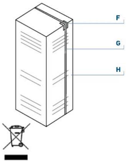
2.1 Installation
Make sure that installation is performed correctly, adhering to all directions in the specific installation manual provided with the appliance.

Warning
Always connect the water before the power.
The appliance must be connected to ground in compliance with electrical system safety standards.
Position the appliance with the aid of a second person.
Never use the open door tolever the appliance into place when fitting.
Avoid exerting too much pressure on the door when open.
The appliance must not be installed near heat sources. If this is not possible, suitable insulation must be used.
The appliance must not be exposed to direct sunlight.
Do not use the appliance outdoors.
Installation and servicing should be carried out by qualified personnel in accordance with current standards.
Have the electrical connection performed by authorised technical personnel.
For avoiding dangers, if the power supply cable is damaged, contact technical support immediately and they will replace it, so as to prevent any risk.
Always use any necessary/ required personal protective equipment (PPE) before performing any work on the appliance (installation, maintenance, positioning or movement).
Before performing any operation on the appliance, switch off the power supply.
This appliance can be used up to a maximum altitude of 4,000 metres above sea level.
If installed near another refrigerator or freezer, keep it at a minimum distance of 2 cm.
Do not try to repair the appliance yourself or without the assistance of a qualified technician.
Do not install/use the appliance outdoors.
CAUTION: while positioning the appliance, make sure that the power supply cable is not caught or damaged.
To prevent instability of the appliance, install and secure it correctly as indicated in the instructions provided in this manual.
2.2 Connection to the water system

natural_image
Diagram of a mechanical component with a coiled cable and flanged end (no text or symbols)The models provided with Ice Maker require a connection to the domestic water supply system. This can be executed only through the provided new water hose with 3/4" threading.
The system pressure must be between 0.05 MPa and 0.5 MPa (between 0.5 bar and 5 bar).
Differences pressures can cause malfunctions or leaks in the water system. The appliance should be supplied only with drinkable water.
Operate as follows:
Unwind the electric cable and connect it directly to the wall socket.
Make sure the appliance is in the Stand-by condition and that all lights are off; should it be not so press the Unit button ⏻ to switch it off.

Back of appliance
Fit one end of the water hose onto the connector at the appliance's back, using the supplied 3/4" fitting [1].
Fit the other end of the hose to the water tap, using the supplied 3/4" fitting [2].
On freezer models only, install the water filter support outside the appliance, using the fittings supplied

natural_image
Two-step diagram showing a pipe fitting with a blue hose and cable, connected to a coiled hose (no text or symbols present)
Warning
The appliance should be supplied only with drinkable water.

Warning
Make sure that installation is performed correctly, according to all of the directions in the specific installation manual provided with the appliance.

Warning
Do not attempt to use a locally sourced garden hose threaded adapter or braided supply line. It will strip the threads on the appliance water connection solenoid.
2.3 Connection to the electrical power supply
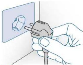
The appliance is equipped with a Schuko type 16A plug and must be connected to the electrical power supply through a corresponding Schuko socket. Do not use extension cords and/or multiple adapters for the power supply connection
natural_image
Illustration of hands using a power plug to install a wall socket (no text or symbols present)
Important
Do not use extension cords and/or multiple adapters for the power supply connection.

Warning
If energy is supplied through an alternative energy power source (solar, geothermal, etc..) or if home automation systems are installed, it is necessary to install the Alternative Energy Kit to integrate the unit into the power grid.
2.4 Refrigerant
The refrigerant isobutane (R600a) is contained within the refrigerant circuit of the appliance, a natural gas with a high level of environmental compatibility, which is nevertheless flammable.
During transportation and installation of the appliance, be certain that none of the components of the refrigerant circuit become damaged.
If the refrigerant circuit should become damaged: - avoid open flames and sources of ignition;
– thoroughly ventilate the room in which the appliance is situated.
ISO 7010 W021
Caution:
risk of fire / flammable materials.

Important
Carry out transportation, installation and/or clearing with extra care so that no damage occurs to the refrigeration circuit.
3.1 Know your Fhiaba
Congratulations for having purchased your new Fhiaba: from now on you can use our innovative conservation system, which will allow you to keep all of your food in the best way possible.
This manual will answer most of your questions about the product's features. Should you require further information, please.
3.2 Manufacturer's liability
The manufacturer declines all liability for damage to persons or property caused by:
use of the appliance other than that specified;
failure to comply with the instructions in the user manual;
tampering with any part of the appliance;
use of non-original spare parts.
3.3 Technical support
In the event of failure of the appliance, contact the technical support and have the repair carried out by qualified personnel only.
make sure you have the model and serial number available on the identification plate.
Use original spare parts only.
Do not try to repair the appliance yourself or without the assistance of a qualified technician: this affects safety and may void the warranty.
Original spare parts remain available for 10 years after the last production of the model.
The following spare parts are available only for authorized repair technicians: electronic boards, thermostats, temperature sensors, hinges, lamps, door handles.Our green number
800-344222 (800-FHIABA)
call us: +39 0434 420160
write us an e-mail at care@fhiaba.com
check our website www.fhiaba.com

Important
Before calling take note of the serial number of the appliance, shown on the warranty certificate and on the serial number plate located inside the refrigerator compartment on the side opposite the door opening.
3.4 Technical data
Refrigerant type, storage volume and other technical data can to be found on the product plate. Further information on all available models can be found at https://www.fhiaba.com/energy-label website (Europe only). This link refers to the official page of the European EPREL product database, the address of which has not been published at the time of printing. Follow the guidelines to find the relevant model. Models can be identified according to the sign placed before the product code bar (E-Nr.) on the product plate. The model can also be found in the first line of the Energy Label.
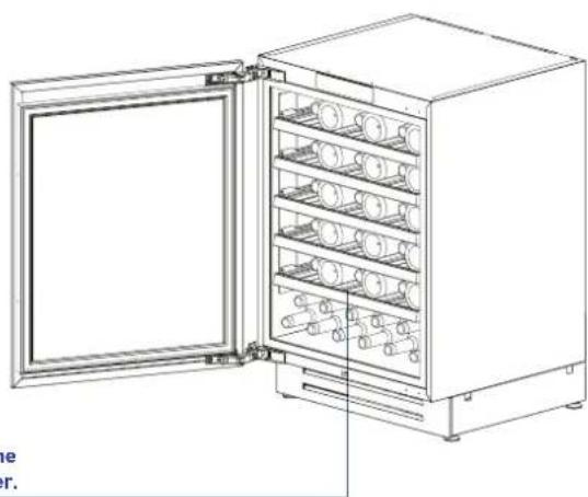
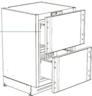
3.5 Product plate
The product plate shows the technical data, the serial number and the model. The product plate must never be removed.

natural_image
Line drawing of an open refrigerator with multiple shelves and doors (no text or symbols)The product plate is positioned inside the equipment in the lower left corner.
The product plate is positioned on the outside of the upper drawer on the left.
natural_image
Line drawing of a multi-level industrial cabinet or oven unit with open doors and internal compartments (no text or symbols)
Conservation Tips
SN (Subnormal) from + 10°C to + 32°C
N (Normal) from + 16°C to + 32°C
ST (Subtropical) from + 18°C to + 38°C
T (Tropical) from + 18°C to + 43°C
4.1 Installation Opening Requirements: Beverage and Wine Cellar Premium Indoor
- Fully integrated / panel ready E - area to be left clear for the power supply cable
Opening Height
Min 873 mm - Max 900 mm (Min 34 3/8" - Max 35 7/16")
Minimum Opening Width
UCB601TP: 600 mm (23 5/8") UCB602TP: 600 mm (23 5/8") UCW601TP: 600 mm (23 5/8") UCW602TP: 600 mm (23 5/8")
Minimum Opening Depth
600 mm (23 5/8")
Door Swing Clearance
1193 mm (46 31/32")
Door Opening Angle
115° / 90° optional
Width
598 mm (23 35/64")
Height
Min 865 mm - Max 890 mm (Min 34 3/64" - Max 35 1/32")
Depth with door (without panel)
572 mm (22 33/63")

Dimensions in parentheses are in inches.


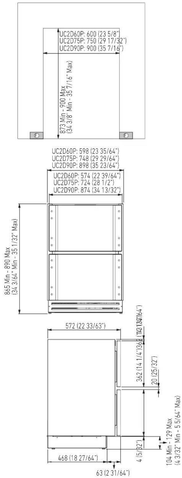
4.2 Installation Opening Requirements: TriMode drawers Premium Indoor
- Fully integrated / panel ready
E - area to be left clear for the power supply cable
Opening Height
Min 873 mm - Max 900 mm
(Min 34 3/8" - Max 35 7/16")
Minimum Opening Width
UC2D60P: 600 mm (23 5/8")
UC2D75P: 750 mm (29 17/32")
UC2D90P: 900 mm (35 7/16")
Minimum Opening Depth
600 mm (23 5/8")
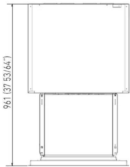
Drawer Swing Clearance
961 mm (37 53/64")
Width
UC2D60P: 598 mm (23 35/64")
UC2D75P: 748 mm (29 29/64")
UC2D90P: 898 mm (35 23/64")
Height
Min 865 mm - Max 890 mm
(Min 34 3/64" - Max 35 1/32")
Depth with door (without panel)
572 mm (22 33/63")

Dimensions in parentheses are in inches.
4.3 Installation Opening Requirements: Beverage and Wine Cellar Premium Outdoor
- Built-in with front and handles, in stainless steel
E - area to be left clear for the power supply cable
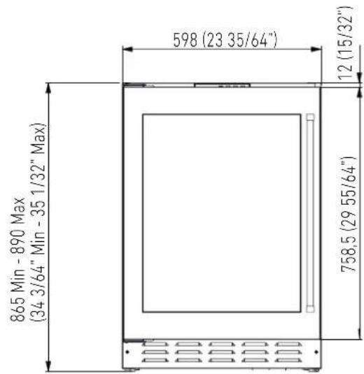
Opening Height
Min 873 mm - Max 900 mm
(Min 34 3/8" - Max 35 7/16")
Minimum Opening Width
UCB601TPO: 600 mm (23 5/8")
UCB602TPO: 600 mm (23 5/8")
UCW601TPO: 600 mm (23 5/8")
UCW602TPO: 600 mm (23 5/8")
Minimum Opening Depth
600 mm (23 5/8")
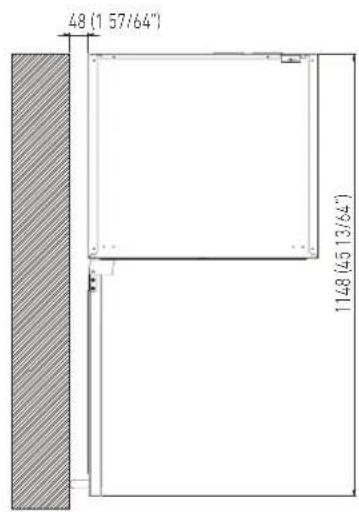
Door Swing Clearance
1148 mm (45 13/64")
Door Opening Angle
115°
Width
598 mm (23 35/64")
Height
Min 865 mm - Max 890 mm
(Min 34 3/64" - Max 35 1/32")
Depth with door
576 mm (22 43/64")

Dimensions in parentheses are in inches.


4.4 Installation Opening Requirements: TriMode drawers Premium Outdoor
- Built-in with front and handles, in stainless steel E - area to be left clear for the power supply cable
Opening Height
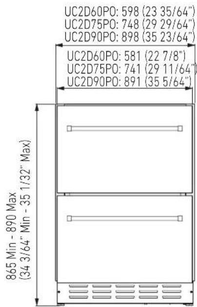
Min 873 mm - Max 900 mm (Min 34 3/8" - Max 35 7/16")
Minimum Opening Width
UC2D60PO: 600 mm (23 5/8") UC2D75PO: 750 mm (29 17/32") UC2D90PO: 900 mm (35 7/16")
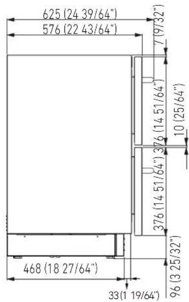
Minimum Opening Depth
600 mm (23 5/8")
Drawer Swing Clearance
1008 mm (39 11/16")
Width
UC2D60P0: 598 mm (23 35/64") UC2D75P0: 748 mm (29 29/64") UC2D90P0: 898 mm (35 23/64")
Height
Min 865 mm - Max 890 mm (Min 34 3/64" - Max 35 1/32")
Depth with drawers
576 mm (22 43/64")

Dimensions in parentheses are in inches.


5.1 Transport to installation site and unpacking

The appliance is very heavy. Take maximum care during handling to avoid injury.

The appliance should always be transported in an upright position. Avoid at all costs leaning it on its front side.
It is recommended to use a manual transporting device to move the appliance to the installation site, and only at this point to remove the base of the packaging.
The appliance should always be transported in an upright position.
If this is not possible, transport the appliance laying on its rear side.
Once at the installation site, the appliance can be taken off the pallet and positioned in the installation area.
5.2 Electrical and Water connection

The Built-in Fhiaba filter cannot make safe any water which is not already suitable for human consumption.

The appliance should be connected only to a potable water supply system.

Do not use extension cords or adapters. Once the appliance has been connected to the water system, turn the Ice Maker off (touch the button ⚙️ on control panel to switch it off) before the main water is shut off.
natural_image
Pure diagram of a mechanical or electrical setup with no visible text, numbers, or symbols
natural_image
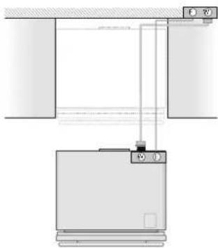
Pure diagram of a mechanical or electrical setup with no visible text, numbers, or symbolsA Schuko 16 A socket with an efficient grounding should be made available for the electrical mains connection, as well as an omnipolar switch which can easily be reached when the appliance is installed.
To connect to the water supply system (for appliances equipped with ice makers) a tap with a male 3/4" connection should be provided, which must also be easily accessible once the appliance is installed.
The appliance is provided with a water supply hose and seal kit which is suitable for high water pressure and complies the Food Regulations.
The water filter cartridge, which is provided with the appliance, should be installed according to the accompanying instructions.
Use only the new hose and the new gaskets which are supplied with the appliance. Discard any hose and gasket which may have previously been installed.
5.3 Anti-Tip Bracket

The anti-tip bracket must be installed to prevent the unit from tipping when doors are fully opened.
TOP MOUNT

natural_image
Line drawing of a refrigerator with two blue arrows pointing to the top panel (no text or symbols present)Operate as follows:
Anti-tip brackets kit provided with the use and care/installation manual
Fix the anti-tip brackets on to the top of the unit (see picture above)
Slide the units into its position in the opening. Level the unit according to the cabinet design.
Make sure the door opens completely and drill four pilot holes in to the bottom of the counter top & fit screws taking care not to pass through the counter fully.
6.1 Change the opening direction of the door (Indoor models)
Open the door
Remove the hinge plastic covers.
Support the door in the open position and use a screwdriver to remove the screws from both hinges.
Do not remove the hinges from the door.
Remove the little caps from the upper and lower holes of the new position and place them in the holes on the opposite side of the unit.
Partially re-install screw #1 in the opposite holes of the unit.
Turn the door upside down and align the hinges with screw #1 to re-position the door.
Re-install screw #2 align the door and tighten all screws securely.
Check that the gasket is aligned with the plastic outline of the front of the unit.
Replace the plastic covers on the hinges.

6.2 Change the opening direction of the door (Outdoor models)

The hinges of the door of the Outdoor models are spring preloaded so never remove the hinges from the stainless steel door.
Open the door
Support the door in the open position and use a screwdriver to remove the screws from both hinges.
Do not remove the hinges from the door.
Remove the little caps from the upper and lower holes of the new position and place them in the holes on the opposite side of the unit.
Turn the door upside down and align the hinges with screw #1 to re-position the door.
Re-install screw #2 align the door and tighten all screws securely.
Check that the gasket is aligned with the plastic outline of the front of the unit.

7.1 Integrated Panel Dimensions
INTEGRATED FRAME
Handles should be installed to the panel prior to installing overlay to door.
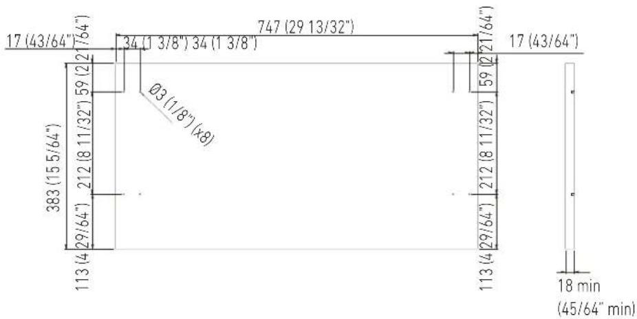
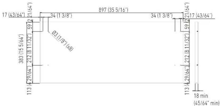
The thickness of the panel should be no less then 18mm (45/64")/no more than 20mm (25/32") and the weight of the overlays should not exceed 10 kg (20 lbs)
Integrated Frame Dimensions: UCB and UCW models
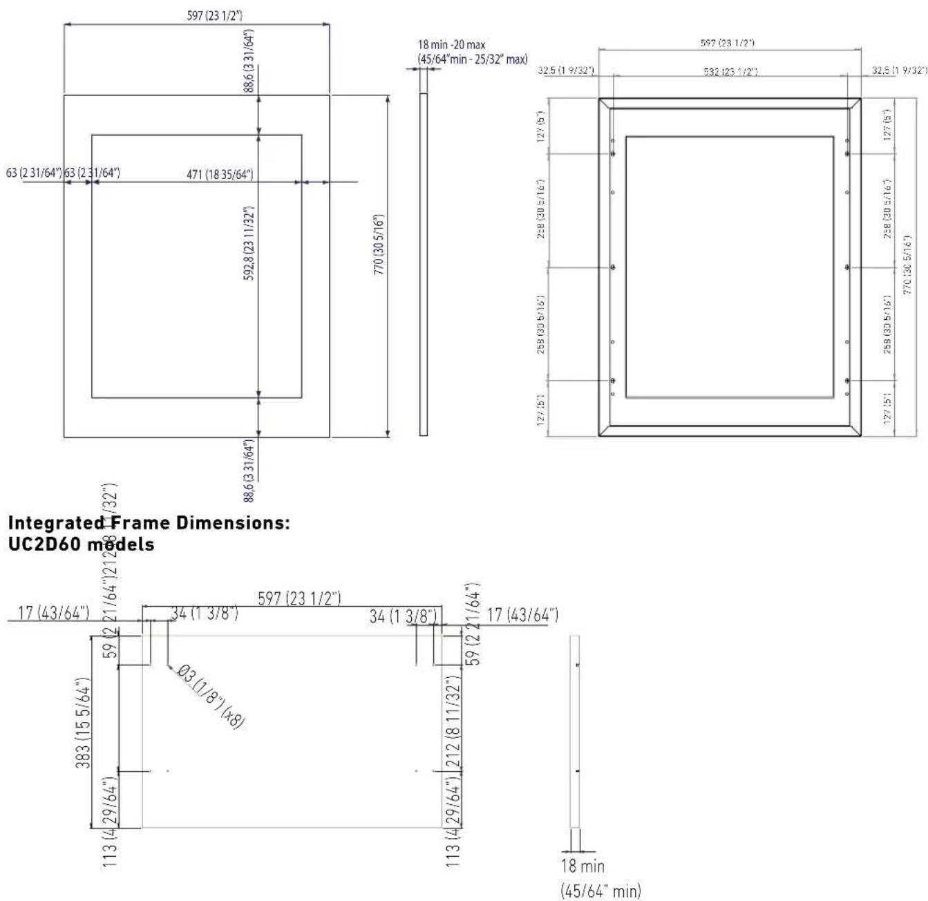
Integrated Frame Dimensions: UC2D75 models
Integrated Frame Dimensions: UC2D90 models
| Premium Indoor models Decorative panel thickness | ||||
| Width | 5 cm (30") 90 cm (36") | |||
| ModelliUCBUCW | Thickness | min 18mm (45/64")max 20mm (25/32") | - | - |
| Max. weight max 8 kg (17 lb) - - | ||||
| ModelliUC2D60UC2D75UC2D90 | Thickness | min 18mm (45/64")max 25mm (1") | ||
| Max. weightSingle panel | max 8 kg (17 lb) max 10 kg (22 lb) max 12 kg (26 lb) | |||
7.2 Mounting the handles

Handles will have to be mounted on the panels before panels are applied to the fridge.
Operate as follows:
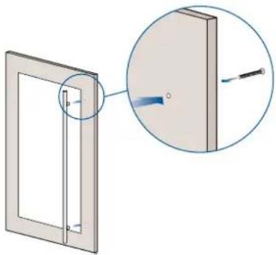
Drill two holes on the back of the panels according to the drawing below [1].
1
natural_image
Diagram showing a door frame with a close-up view of a wooden post (no text or symbols present)Place the handle on top of the holes and insert the screws through the panel and into the handle support [2].
2

natural_image
Diagram showing a door frame with an inset close-up of a vertical rod and a curved arrow indicating rotation (no text or symbols)
| ∅ 30 mm | HANDLE PRODUCT CODE | ||
| H08 H07 H05 | |||
| Length A | 794 mm(31 1/4") | 644 mm(25 3/8") | 494 mm(19 5/8") |
| Distance between fixing points X | 480 mm(18 7/8") | 490 mm(19 1/4") | 340 mm(13 3/8") |
| Series 90 75 60 | |||
| ∅ 18 mm | HANDLE PRODUCT CODE | ||
| HC8 HC7 HC5 | |||
| Length A | 794 mm(31 1/4") | 644 mm(25 3/8") | 494 mm(19 5/8") |
| Distance between fixing points X | 776 mm(30 1/2") | 626 mm(24 5/8") | 476 mm(18 3/4") |
| Series 90 75 60 | |||
7.3 Installation of decorative panels
Once the unit is positioned inside the opening and the screws of the anti-tipping supports are tightened, the machine will no longer move and it will be possible to take the measures for aligning the overlay panel.
Measure the distance between the aluminum frame of the door and the adjacent furniture panels. Subtract the millimeters needed for the dimension of the gap that you want to be left between the panels.
Center the panel horizontally and vertically, marking some references on it.
Refer the taken measurements to the back of the panel.

7.4 Mounting panel to the door

Before beginning installation make sure handle is installed to the panel prior to installing panel to door.
Operate as follows:
Open the door and remove the gasket carefully starting at the corner. Continue to pull gasket free from gasket channel [1].
Upon removal, lay gasket down on a flat surface.

natural_image
Technical line drawing of a window frame with an inset showing a magnified detail (no text or symbols)Remove the two vertical gasket channel trims starting from the corner [2].

natural_image
Line drawing of a rectangular frame with vertical supports and a flat top, no text or symbols presentOpen the door.
Position the panel in front of the glass door, respecting the references given in point 7.3 [3].
Fix the panel with clamps making sure not to indent the face of the panel.

natural_image
Line drawing of a cabinet with two doors, one open and one closed, both labeled with number 3 (no text or symbols on the cabinet itself)Locate 6 of the M5x38 mm screw provided with your unit [4]. Place one screw into each of the 6 holes and screw down and do not overtighten screws.
Remove tape and clamps from door.
Reposition the two vertical gasket channel trims starting from the corner.
Reposition gasket carefully starting from the corner.

natural_image
Illustration of hands installing or adjusting a rectangular panel with a screwdriver (no text or symbols)Once the correct alignment of the panel has been checked, place the last two screws onto the top and bottom hinge [5].

natural_image
Line drawing of an open refrigerator with internal components, showing exterior and interior views (no text or symbols)7.5 Mounting panels to the drawers

Before beginning installation make sure handle is installed to the panel prior to installing panel to door.

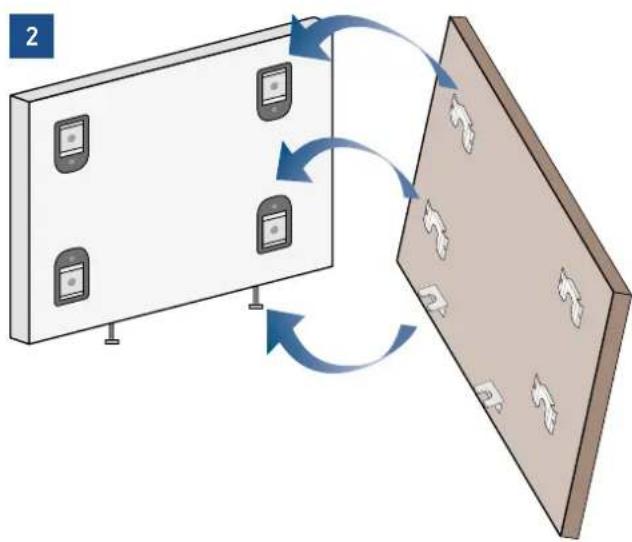
Once all brackets and small brackets have been applied to the panels, you can begin installing the bottom drawer.
Operate as follows:
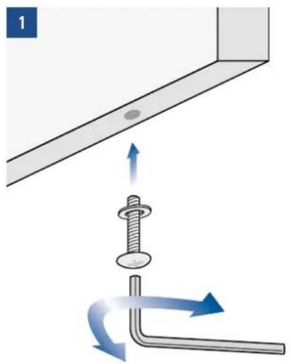
Partially tighten the screw to the fixing [1].
natural_image
Diagram showing a screw being inserted into a bent pipe with directional arrows indicating motion (no text or symbols)Hook the bottom drawer panel starting from the fixings on the bottom [2].
flowchart
graph TD
    A["Device 1"] -->|Data Flow| B["Device 2"]
    B -->|Data Flow| C["Device 3"]
    C -->|Data Flow| D["Device 4"]
    D -->|Data Flow| E["Device 5"]
    E -->|Data Flow| F["Device 6"]
    F -->|Data Flow| G["Device 7"]
    G -->|Data Flow| H["Device 8"]
    H -->|Data Flow| I["Device 9"]
    I -->|Data Flow| J["Device 10"]
    J -->|Data Flow| K["Device 11"]
    K -->|Data Flow| L["Device 12"]
    L -->|Data Flow| M["Device 13"]
    M -->|Data Flow| N["Device 14"]
    N -->|Data Flow| O["Device 15"]
    O -->|Data Flow| P["Device 16"]
    P -->|Data Flow| Q["Device 17"]
    Q -->|Data Flow| R["Device 18"]
    R -->|Data Flow| S["Device 19"]
    S -->|Data Flow| T["Device 20"]
Depth alignment: working from the inside of the drawer, after lifting up the magnetic seal, adjust the panel position so it is closer to or further away from the door using the holes and then secure the panel using the holes [3].

8.1 Ventilation
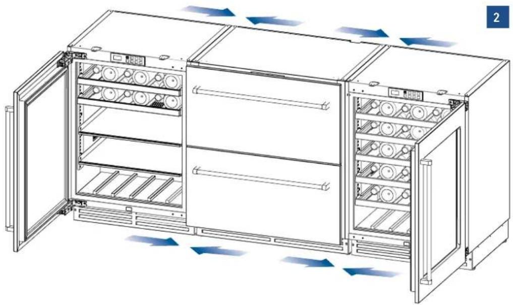
A forced air system assures ventilation through a grille positioned in the lower front part of the unit.


| A | 200mm (7 7/8") |
| B | 60mm (2 3/8) |
If the kitchen design includes a kickplate (plinth), it must be positioned at least 1/4" away from the face of the kick area and be ventilated in such a manner as to provide 50% of the material removed for proper ventilation and operation of the appliance.
Holes can be in any shape and size, as long as the total area of the punched part equals 50% of the kickplate and align with the intake and output openings of the appliance. [1]

The air intake and outlet must not be blocked or covered in any way.
9.1 Door swing, door stop
The Door of the unit will open 115° straight from the factory.
You can stop the door at 90° by using the provided pin and before placing the unit under the counter

natural_image
Technical line drawing of a mechanical assembly with mounting brackets and structural components (no text or symbols)10.1 Post installation checklist
√ Check that the front levelling feet have been properly installed.
√ Check that the connection to the water system does not have any leaks and that the shutoff valve is easily accessible.
√ Check that the electrical connection is correctly installed and that the socket is easily accessible.
√ Check for perfect alignment of the appliance with adjacent structures.
√ Check that all adhesive tape and external or internal temporary protective devices have been removed.
√ Check for perfect closing of the doors and the smooth sliding of the drawers and shelves.
√ Check the alignment if 2 or more models are installed side by side; (there are no kits for joining the equipment). [2]
90° hinge stop installation
Open the door at 90°
Slide hinge pin into hole as shown in picture [1]
You might need an hammer to gently tap the pin into its final position
natural_image
Technical line drawing of an open industrial refrigerator with cooling fans and ventilation slots (no text or symbols)11.1 Main components

natural_image
Line drawing of an open refrigerator with shelves and doors (no text or symbols)BEVERAGE:
Inner cabinet in AISI 304 stainless steel
Outer cabinet in AISI 304 stainless steel
Interactive control panel with OLED display
Modular shelf positioning system
Bead-blasted stainless steel internal drawer with tempered glass front
Bottle storage shelves
White and Amber LED lighting
Reversible door
Glass door with UV protection and Argon gas

natural_image
Line drawing of a stainless steel oven with multiple compartments and one door open (no text or symbols)DUAL TEMPERATURE WINE CELLAR:
Inner cabinet in AISI 304 stainless steel
Outer cabinet in AISI 304 stainless steel
Interactive control panel with OLED display
Modular shelf positioning system
Bottle storage shelves
White and Amber LED lighting
Reversible door
Glass door with UV protection and Argon gas
natural_image
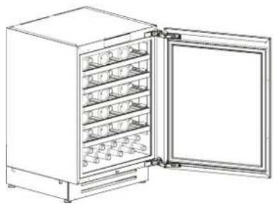
Line drawing of a refrigerator with multiple compartments and one open door (no text or symbols)SINGLE TEMPERATURE WINE CELLAR:
Inner cabinet in AISI 304 stainless steel
Outer cabinet in AISI 304 stainless steel
Interactive control panel with OLED display
Modular shelf positioning system
Bottle storage shelves
White and Amber LED lighting
Reversible door
Glass door with UV protection and Argon gas

natural_image
Line drawing of a multi-level industrial cabinet or enclosure with doors and internal compartments (no text or symbols)TRIMODE SLIDING DRAWERS:
Inner cabinet in AISI 304 stainless steel
Outer cabinet in AISI 304 stainless steel
Interactive control panel with OLED display
Water filter (*)
Modular shelf positioning system
Bead-blasted stainless steel internal drawer with tempered glass front
Automatic ice maker (*)
LED lighting
TriMode freezer drawers which can be converted into a fridge or Fresco compartment
(*) on some models
12.1 Main control panel
Beverage Center 1 Single Zone Wine Cellar 1 Single Zone TriMode / Convertible Drawers

Beverage Center Dual Zone Wine Cellar Dual Zone

12.2 Layout
The control panel is made up of a 1.51" 128x64 pixel display with an 8-button resistive keypad, including backlit ON/OFF button. The low-voltage power supply is provided to the control board via a CAN bus connection cable.
12.3 Functions
Displays the set-point of the one or two compartments (WINE CELLAR/BEVERAGE CENTER models only)
Displays the operating variables
For setting the temperature set-point
Notification of anomalous faulty events such as:TEMPERATURE ALARMS
FAULTS
WARNINGSCloud connection via accessory Ethernet, Wi-Fi, 3G modules.
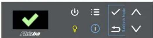
12.4 Keypad

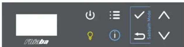
Unit ON/OFF

Main menu access button
Compartment lighting ON/OFF button
Information menu button

Confirm operation button

Exit menu/Whole or decimal number selection (for Celsius only)

Up

Down
13.1 Switching ON/OFF 14.1 How to adjust Switching ON

When the appliance is switched off, the backlight in the ON/OFF button ⏻ is RED. Press and briefly hold the ON/OFF button ⏻ to turn the appliance on. The text POWER ON... appears for a few seconds.


Switching OFF
Press and hold the ON/OFF button ⏻ until the appliance is switched off.
the temperature to meet user requirements
Beverage Center Single Zone Wine Cellar Single Zone TriMode / Convertible Drawers
Entering the set-point
Press the MENU button ☐ to call up the M1 frame
Press the CONFIRM button √

Enter the new set-point value using the UP/DOWN buttons. Press the CONFIRM button √ to set the new value or press the BACK button ↩ to exit the menu without saving the new value.
Beverage Center Dual Zone Wine Cellar Dual Zone
Entering set-points

Press the MENU button ☐ to call up the M1 frame Select the set-point you wish to edit by pressing the CONFIRM button √ (the set-point selected for editing starts to flash)

Enter the new set-point value using the UP/DOWN buttons. Press the CONFIRM √ button to set the new value. Both set-point values are saved. Press the BACK button → to exit the menu without saving the new values.
15.1 Event notifications
Pre-alarm status
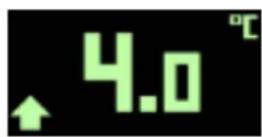
When the temperature limits are exceeded but the alarm delay time has not yet expired, the device is in pre-alarm status. The UP arrow icon appears during 'high temperature' pre-alarm status. The DOWN arrow icon appears during 'low temperature' pre-alarm status.
Alarm detection

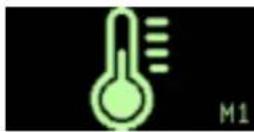
When a temperature alarm arises, the THERMOMETER icon appears, the buzzer goes off and the red LED flashes. Press any button to open the EVENTS LIST and turn the buzzer off. Press the BACK button
to exit the EVENTS LIST. If the alarm condition resolves itself, the buzzer goes off automatically.
Active alarm

During a high/low temperature alarm condition, the UP/DOWN arrow icon with flashing red LED appears on the left-hand side of the display. If the alarm condition resolves itself, the buzzer goes off automatically.
Fault detection

When a fault arises, the TOOL icon appears, the buzzer sounds and the red LED flashes. Press any button to open the EVENTS LIST and turn the buzzer off. Press the BACK button → to exit the EVENTS LIST.
If the alarm condition resolves itself, the buzzer goes off automatically.
Active fault
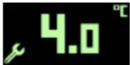
During a fault condition, the TOOL icon with flashing red LED appears on the left-hand side of the display. If the fault condition resolves itself, the buzzer goes off automatically.
Rectified event notification

If a temperature or fault condition resolves itself before the EVENTS LIST has been consulted, the 'message' icon appears on the left-hand side of the frame.
Open door warning
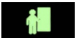
If the door has been left open, after a pre-set delay time, the icon shown in the figure appears and the buzzer goes off.
Voltage out of range warning

The supply voltage WARNING fills the whole frame with a dedicated icon. The buzzer sounds when any button is pressed or the time set in the BUF parameter has expired. If the problem is not rectified, the warning will be repeated after 24 hours.
15.2 Wine cellar and beverage event notifications
Pre-alarm status
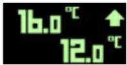
Top compartment pre-alarm

Bottom compartment pre-alarm
When the temperature limits are exceeded but the alarm delay time has not yet expired, the device is in pre-alarm status for one or both of the compartments. The UP arrow icon appears alongside the compartment's set-point value during 'high temperature' pre-alarm status. The DOWN arrow icon appears alongside the compartment's set-point value during 'low temperature' pre-alarm status.
Alarm detection

When a temperature alarm arises in one or both of the compartments, the THERMOMETER icon appears, the buzzer sounds and the red LED flashes. Press the INFO button to open the EVENTS LIST and turn the buzzer off. Press the BACK button → to exit the EVENTS LIST. If the alarm condition resolves itself, the buzzer goes off automatically.
Active alarm

During a high/low temperature alarm condition, the UP/DOWN arrow icon with flashing red LED appears alongside the compartment's set-point value and the buzzer sounds. Press the INFO button to open the EVENTS LIST and turn the buzzer off. If the alarm condition resolves itself, the buzzer goes off automatically.
Fault detection

When a fault arises, the TOOL icon appears, the buzzer sounds and the red LED flashes. Press the INFO button to open the EVENTS LIST and turn the buzzer off. Press the BACK button → to exit the EVENTS LIST.
If the alarm condition resolves itself, the buzzer goes off automatically.
Active fault

During a fault condition affecting one or both compartments, the TOOL icon with flashing red LED appears on the left-hand side of the display. Press the INFO button to open the EVENTS LIST and turn the buzzer off.
If the fault condition resolves itself, the buzzer goes off automatically.
Rectified event notification
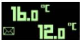
If a temperature or fault condition resolves itself before the EVENTS LIST has been consulted, the 'message' icon appears on the left-hand side of the frame.
16.1 Special functions
Chill and serve

Chill and serve active

Chill and Serve active, Zone 1

Chill and Serve active, Zone 2

Chill and Serve active in both compartments
Set-point forcing to 4 degrees in the relative compartment for one hour (Wine Cellar only, even with only one compartment). This is activated/deactivated by simultaneously pressing:
CONFIRM √ + UP for single-compartment Wine Cellars or for compartment 1 of dual compartment Wine Cellars.
CONFIRM √ + DOWN for compartment 2 of dual compartment Wine Cellars
Activation is confirmed by the buzzer sounding and the snowflake icon appearing on the screen.
Sabbath mode
This is activated/deactivated by simultaneously pressing the CONFIRM √ + BACK buttons ↻.
Temperature stabilisation is carried out based on the time parameters set by the manufacturer
The fans come on at the same time as the compressor
The evaporator fans are not inhibited when the door is open
Defrosting is inhibited
All alarms are disabled
Light outputs always switched off
The display stays off
16.2 User menus
These can be accessed by pressing the MENU button. Select the required menu using the UP/DOWN buttons and pressing the CONFIRM button. The menu index, from M1 to M6 is shown in the bottom right-hand corner of the display.

Temperature set-point setting

Humidity set-point setting

Alarm limits setting

Start defrost operation

Events list

Service menu
Entering the set-point
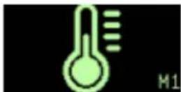
Press the MENU button ☐ with frame M1 selected to access the temperature set-point setting. See Chapter 3.0
Humidity set-point setting

Function not enabled
Event icons

High temperature

Low temperature

High temp. due to open door

High board temperature

Probe fault
Start defrost operation

Single compartment
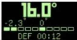
Home Page


Dual compartment Wine Cellar
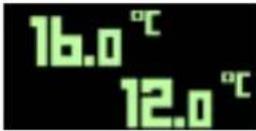
Home Page
With frame M4 selected, press the CONFIRM button to start a defrost operation (if the right conditions for execution are met). If conditions are not met, the X frame appears (request denied).
WAIT PHASE
The defrosting operation may include an initial wait time during which the 00:00 timer does not increase until the cycle actually starts.
PHASE ACTIVE
During the defrost operation the progress bar fills up from left to right and the timer starts counting. The value displayed at the centre of the frame indicates the temperature in the compartment while the value on the left shows the temperature of the evaporator.
ABORT
Defrosting can be aborted by pressing the MENU button during the wait time and during execution, but not during the dripping phase. Once defrosting has been completed, the display returns to the Home page. If a dripping time is envisaged the Drip icon appears and once this has expired the display returns to the Home page.
AUTOMATIC DEFROST
If defrosting is started automatically by the controller, the DEFROST frame does not appear, instead the Home Page remains showing the defrost icon.
Events list

FAULT RECORD STRUCTURE
Representative Icon — Fault reference The frame alongside shows an example of an S1 thermostat sensor fault.
ALARM RECORD STRUCTURE
Representative icon — Peak — Duration in minutes The frame alongside represents a high temperature alarm
ALARM RECORD STRUCTURE FOR WINE CELLAR
Representative icon - Compartment index — Peak — Duration in minutes
The frame alongside shows a high temperature alarm for compartment 1
and a temperature alarm for compartment 2.
With the M5 frame selected, press the CONFIRM button to call up the EVENTS LIST. If the list is empty, the empty trash can icon appears for 3 seconds after which the display returns to the Home Page. If there are any events in the list, the + symbol shows that other events have been recorded which can be scrolled through using the UP button.
If the display panel is switched off any recorded events are deleted as the device does not have an internal clock.
Be sure to check event logs prior to trying to reset the power as a troubleshooting method.
17.1 Lighting
The beverage centre is lit up with white LED lights.
The Wine Cellars are lit up with amber and white LED strip lights. Amber light for lighting during wine aging and white for lighting up the cellar when the door is opened.
The TriMode drawers are lit up with white LED lights.
In the event of faults and/or breakdowns in the lighting system, contact Fhiaba Service.
18.1 General directions
Your Fhiaba is designed to ensure precise, constant temperatures and appropriate humidity levels in all compartments.
Nevertheless, to properly preserve all of your foods, it is not enough to have an excellent refrigerator. It is also necessary to understand best practices for correct food preservation.
Do bear in mind that all foods will inevitably change their characteristics over the passage of time. This change begins long before the food is consumed, since foods contain micro organisms which multiply and can cause deterioration. This process occurs more rapidly due to improper handling, preservation temperatures and humidity levels.
It is therefore recommended to follow the directions presented below which will permit using your appliance in the most effective and safe manner to keep your foods and beverages in the best way for as long as possible.
Bear in mind that TriMode drawer models configured as Fresco compartments are best for preserving the most delicate fresh foods, since it ensures constant average temperature near freezing.
19.1 Care and Cleaning
To clean the parts made of steel use a microfiber cloth and the sponge provided in the kit with the appliance. Always use the cloth and sponge in the direction of the steel's satin finish.
Every now and then, to polish the steel, wipe with a slightly damp microfiber cloth.
Do not use the sponge on aluminium parts, such as the handles and the profiles of the glass shelves.
You should use special care to keep the ventilation openings in the appliance or in the cabinet that houses it, free of obstructions.

Note
Scrupulously follow the detailed directions that can be found in the provided kit and never use abrasive or metallic products which could scratch and damage the satin finishing on the appliance permanently.
19.2 Condenser cleaning
A ventilation grille is located at the bottom.
To clean it use a vacuum cleaner with a soft brush attachment at maximum power, sweeping it along the vent slits. In case of a significant dust build up, the ventilation grille can be removed to allow a more accurate cleaning of the filter.
19.3 Internal cleaning
Clean the internal and removable parts by washing them with a solution of lukewarm water with a small amount of dishwashing detergent.
Rinse and dry right away.
Do not use mechanical devices or other methods to speed up defrosting.

Note
Do not bring cold glass parts into contact with boiling water.
Do not wash any parts of the refrigerator in a dishwashing machine since this could damage or irreparably deform the parts.

Warning
Do not use water on the electrical parts, lights and control panel.
19.4 Replacement of "activated carbon filter".
The request to change the filter appears on the display [1], replace the filter.

1
Remove the upper wooden shelf [2] and remove its side guide [3].
At the bottom is the filter [4].

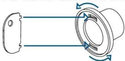
Insert the appropriate key, turn, remove the filter and replace it with the new one.
Then insert the lateral runner and the shelf. [5].
natural_image
Diagram of a mechanical component with directional arrows indicating rotation or flow (no text or symbols)5
Reset the message on the display by holding down OK ( √ ) [6].

6

- INDICAZIONI IMPORTANTI PER LA SICUREZZA E PER L'AMBIENTE 4
- Installazione
- Attenzione
- Importante
- Ventilazione
- BEVERAGE:
- CANTINA VINI 2 TEMPERATURE:
- CANTINA VINI 1 TEMPERATURA:
- CASSETTONI TRIMODE:
- Composizione
- Beverage Center 2 temperature Cantina Vini 2 temperature
- IMPORTANT DIRECTIONS FOR SAFETY AND THE ENVIRONMENT 42
- INSTALLATION 43
- BEFORE STARTING 44
- TECHNICAL REQUIREMENTS 46
- PREPARING THE INSTALLATION 50
- DOOR SWING 52
- PANEL MOUNTING 54
- VENTILATION 61
- DOOR SWING 62
- POST INSTALLATION 62
- FEATURES 63
- GETTING STARTED 64
- SWITCHING ON/OFF 66
- ADJUSTMENTS 66
- EVENT NOTIFICATIONS 67
- SETTINGS AND SPECIAL FUNCTIONS 69
- LIGHTING 72
- GENERAL DIRECTIONS 72
- CARE AND CLEANING 73
- For your safety
- Important information when using the appliance
- Explosion hazard!
- Note
- Important
- Attention
- Caring for the environment
- Power voltage
- Danger of electrocution
- Plastic packaging
- Danger of suffocation
- Cleaning, sanitization and maintenance of the ice and/or water dispenser (if present)
- Warning
- Informations for control bodies
- To save energy
- Environmental labelling
- Installation
- Connection to the water system
- Operate as follows:
- Back of appliance
- Connection to the electrical power supply
- Refrigerant
- Caution:
- Know your Fhiaba
- Manufacturer's liability
- Technical support
- Technical data
- Product plate
- Conservation Tips
- Installation Opening Requirements: Beverage and Wine Cellar Premium Indoor
- Opening Height
- Minimum Opening Width
- Minimum Opening Depth
- Door Swing Clearance
- Door Opening Angle
- Width
- Height
- Depth with door (without panel)
- Installation Opening Requirements: TriMode drawers Premium Indoor
- Drawer Swing Clearance
- Installation Opening Requirements: Beverage and Wine Cellar Premium Outdoor
- Depth with door
- Installation Opening Requirements: TriMode drawers Premium Outdoor
- Depth with drawers
- Transport to installation site and unpacking
- Electrical and Water connection
- Anti-Tip Bracket
- Change the opening direction of the door (Indoor models)
- Change the opening direction of the door (Outdoor models)
- Integrated Panel Dimensions
- INTEGRATED FRAME
- Mounting the handles
- Installation of decorative panels
- Mounting panel to the door
- Mounting panels to the drawers
- Ventilation
- Door swing, door stop
- Post installation checklist
- 90° hinge stop installation
- Main components
- DUAL TEMPERATURE WINE CELLAR:
- SINGLE TEMPERATURE WINE CELLAR:
- TRIMODE SLIDING DRAWERS:
- Main control panel
- Layout
- Functions
- Keypad
- Switching ON/OFF 14.1 How to adjust Switching ON
- Switching OFF
- the temperature to meet user requirements
- Beverage Center Single Zone Wine Cellar Single Zone TriMode / Convertible Drawers
- Beverage Center Dual Zone Wine Cellar Dual Zone
- Event notifications
- Wine cellar and beverage event notifications
- Special functions
- Sabbath mode
- User menus
- Entering the set-point
- Humidity set-point setting
- Event icons
- Start defrost operation
- WAIT PHASE
- PHASE ACTIVE
- ABORT
- AUTOMATIC DEFROST
- FAULT RECORD STRUCTURE
- ALARM RECORD STRUCTURE
- ALARM RECORD STRUCTURE FOR WINE CELLAR
- Lighting
- General directions
- Care and Cleaning
- Condenser cleaning
- Internal cleaning
- Replacement of "activated carbon filter".
Brand : Fhiaba
Model : UCB601TGMO
Category : Refrigerator