MS-A5001 - Receiver JBL - Free user manual and instructions
Find the device manual for free MS-A5001 JBL in PDF.

| Product Type | Car Audio Amplifier |
| Number of Channels | 5 |
| Power Output (RMS) | 50 W x 4 + 250 W x 1 at 4 ohms |
| Maximum Power Output | 150 W x 4 + 500 W x 1 at 2 ohms |
| Impedance | 2 - 8 ohms |
| Frequency Response | 20 Hz - 20 kHz |
| Signal-to-Noise Ratio | > 85 dB |
| Total Harmonic Distortion | < 0.1% |
| Built-in Crossover | Low-pass, high-pass, full-range selectable |
| Bass Boost | 0 - 12 dB at 45 Hz |
| Input Sensitivity | 200 mV - 4 V |
| Dimensions (W x H x D) | 340 x 55 x 180 mm |
| Weight | 3.2 kg |
| Power Supply | 12 V DC (vehicle electrical system) |
| Fuse Rating | 30 A x 1 |
| Protection Circuits | Thermal, short circuit, over-voltage, under-voltage |
| Input Connections | RCA line inputs (front, rear, subwoofer) |
| Speaker Connections | Screw terminals |
| Color | Black |
| Recommended Use | Car audio system upgrade |
Frequently Asked Questions - MS-A5001 JBL
User questions about MS-A5001 JBL
0 question about this device. Answer the ones you know or ask your own.
Ask a new question about this device
Download the instructions for your Receiver in PDF format for free! Find your manual MS-A5001 - JBL and take your electronic device back in hand. On this page are published all the documents necessary for the use of your device. MS-A5001 by JBL.
USER MANUAL MS-A5001 JBL
text_image
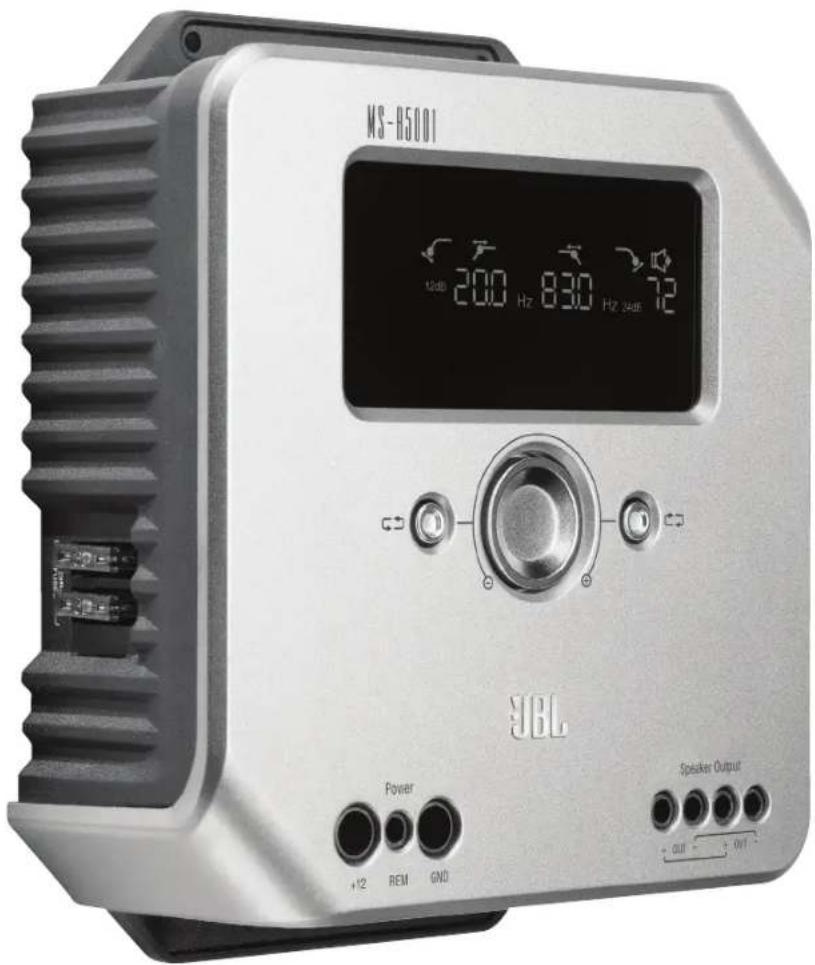
JBL by HARMAN®Ms-A5001
Digital signal processing amplifier
text_image
M8-H5001 12dB 200 Hz 830 Hz 24dB YBL Power +12 REM GND Speaker Output + OUT - + OUT -User GUide

Ms-A5001 FeATUres
① Input-Level Control
This control is used to match the input sensitivity to the signal voltage for proper analog-to-digital conversion. See page 7 for details. DO NOT use this control to set the relative output level of amplifier channels!
② Input Signal Selector
Lo/Hi/Hi2 sets input voltage and impedance range. See page 7 for details.
③Audio Inputs
Use RCA audio cables for preamp-level connections or _ attach the included RCA to bare wire adapters for speaker-level input connections.
④ Pass-Through Outputs
Input channel 1 sends signals to Output 1. Input channel 2 sends signals to Output 2. The MS-A5001's filter settings do not affect these channels.
⑤ Onboard Fuses
2 x 40A ATC type.
⑥ Display Panel
Displays the amplifier's settings.
⑦ User Controls
These controls allow you to adjust the amplifier's settings. See page 9 for details.
⑧ +12V Power Input
Connects to your vehicle's battery with a 80A fuse within 18 inches (45.7cm) of the battery's positive terminal.
⑨ Remote Turn-On Input
Connects switched +5V to +12V. Note: The MS-A5001 also includes signal-sensing turn-on. You may choose the turn-on method during setup. See pages 5 and 9-10 for details.
⑩ Chassis Ground Input
Connect to a paint-free spot on the vehicle chassis.
⑪Speaker Outputs
Two mono speaker outputs. These outputs send the same output signal (in parallel) for the added convenience of connecting multiple subwoofers. Be sure to account for parallel resistance connections when you determine the load on the MS-A5001's output. Do not connect loads below a total of two ohms.
Ms-A5001
diGiTAL siGNAL-PrOCessiNG AMPLiFier
PLeAse reAd This BeFOre YOU BeGiN!
JBL ^® MS-series amplifiers include many features not found on conventional car-audio amplifiers. As a result, the setup procedure for JBL MS-series amplifiers is different from that of conventional car-audio amplifiers. The following overview of features and functions will help you plan a great system and make the best use of the MS-A5001's innovative features.
About the digital signal processing (DSP) included in MS-series amplifiers:
All of the signal processing in MS-series amplifiers is digital. Digital signal processing, along with the amplifiers' intuitive controls and display, make precise setup easy. Only the input-level controls are analog.
Will I lose my settings if I disconnect the amplifier or the car's battery?
No. The MS-A5001 stores all of the DSP settings in nonvolatile memory, so you will not lose any settings if power is removed.
Why are the input-level controls analog?
In order to provide the best signal-to-noise ratio and to maximize the resolution of the digital-to-analog conversion, the maximum input-signal level to the analog-to-digital (A/D) converters must be precisely set. The control that sets the level must be an analog control. The included setup CD and the procedure described in this manual make setting the level simple and precise. Once you set the input-level control, do not use the control to "tune" the system. Use the digital output-level control to adjust the relative level between amplifier channels to tune the system.
FCC REGULATIONS
Caution:
Changes or modifications not expressly approved by the party responsible for compliance could void the user's authority to operate the equipment.
Compliance statement:
1: This device is verified to comply with Part 15 of the FCC Rules. Operation subject to the following two conditions: (1) this device may not cause harmful interference, and (2) this device must accept any interference received, including interference that may cause undesired operation.
2: This equipment has been tested and found to comply with the limits for a Class B digital device, pursuant to Part 15 of the FCC Rules. These limits are designed to provide reasonable protection against harmful interference in a residential installation. This equipment generates, uses and can radiate radio frequency energy and, if not installed and used in accordance with the instructions, may cause harmful interference to radio communications. However, there is no guarantee that interference will not occur in a particular installation. If this equipment does cause harmful interference to radio or television reception, which can be determined by turning the equipment off and on, the user is encouraged to try to correct the interference by one or more of the following measures:
- Reorient or relocate the receiving antenna.
- Increase the separation between the equipment and receiver.
- Connect the equipment into an outlet on a circuit different from that to which the receiver is connected.
- Consult the dealer or an experienced radio/TV technician for help.
Why are the signal inputs and speaker outputs numbered rather than labeled "right" and "left"?
MS-series amplifiers are designed to make integration into any system simple and straightforward. The amplifier includes a digital input-mixer control that eliminates the need for Y adapters. It allows a mono or stereo signal to drive any pair of output channels for maximum system-building flexibility. Labeling the channels "left" and "right" would be confusing in some applications.
How does the digital input mixer work?
The MS-A5001 converts the signals from each RCA-type input connector into digital signals and sends them to its digital signal processor. The DSP routes the signals to the speaker output according to the selections in the input mixer. There's one input mixer for channels 1 and 2 that feeds the mono output channel. Selecting "1" in the input mixer for channels 1 and 2 will send only the signal connected to input jack 1 to the mono output channel. Use this setup if the subwoofer input is already mono or if the intended signals come from only one channel. (See Figure 1.)
Figure 1

flowchart
graph LR
    A["Input 1"] --> D["DSP"]
    B["Input 2"] --> D
    D --> E["Output"]
Selecting "1.2" in the input mixer sends a summed mono signal to the output. This selection is useful for sending a stereo signal to the mono output when using subwoofers intended to receive information from both the left and right inputs. (See Figure 2.)
Figure 2

flowchart
graph LR
    A["Input 1"] --> D["DSP"]
    B["Input 2"] --> D["DSP"]
    D --> E["Output"]
Many system configurations are possible. None of them need Y adapters. See "System Diagrams" (pages 12 and 13) for more examples.
Does the amplifier include speaker-level and line-level inputs?
Yes. MS-series amplifiers can accept any input signal. If your head unit includes RCA-type outputs, simply plug them into the RCA-type input jacks. If your head unit doesn't include RCA-type outputs (as is the case with all factory-installed systems), use the included RCA-to-bare-wire adapters. Be sure to observe proper polarity. The signal inputs are differential and will accept any signal from 100mV (low-level) to 20V (high-level). There's no need to use separate adapters or to determine the signal voltage or type precisely. MS-series amplifiers' on-board tools and the setup procedure described later in this manual will make optimizing the configuration simple.
The factory-installed system in my car shows a "speaker disconnected" message or fails to play when a speaker is disconnected or when an amplifier is connected to its output. What should I do?
MS-series amplifiers include three input-level switch positions: Lo, Hi and Hi2. The Hi2 position includes a circuit designed to fool the factory system into "seeing" a speaker connected to its output. If your car has one of these systems, set the input level control to "Hi2" and follow the rest of the setup instructions.
My factory-installed head unit doesn't include a remote-turn-on wire. What should I do?
MS-series amplifiers include signal-sensing turn-on. They never require a remote turn-on connection. The amplifier will sense the presence of an audio signal on its inputs, and it will turn on automatically. A few minutes after the signal stops or after the vehicle's radio is turned off, the amplifier will turn itself off automatically. During the delay, the amplifier draws very little current so that it won't drain the vehicle's battery.
What is the best procedure for choosing a crossover frequency and slope? (Figures 3a & 3b)
A crossover is a pair of filters that divide the audio signal into low frequencies (bass) and high frequencies (treble) so each band of frequencies goes to the speaker designed to play it. For example, a tweeter is designed to play only high frequencies, and too much bass can damage it. A woofer is designed to play only low frequencies and does a poor job of reproducing high frequencies. A midrange speaker is designed to play frequencies between bass and treble (midrange frequencies). Figure 3a shows how these speakers would be divided up across the 20Hz – 20kHz range using the appropriate filters (that is, the appropriate crossovers).
Figure 3a
Figure 3b

line
| Filter Type | Value | |---|---| | Low-Pass Filter | 4 | | Band-Pass Filter | 4 | | High-Pass Filter | 4 |
line
| Parameter | Value | | :--- | :--- | | 6dB/oct | 6 | | 12dB/oct | 12 | | 24dB/oct | 24 |When setting a crossover between a low-frequency speaker and a high-frequency speaker, choose the high-pass filter (HPF) frequency that will keep the high-frequency speaker safe. Set the low-pass filter (LPF) so the hand-off provides smooth response in the region near the crossover frequency. When implementing a crossover between speakers, use steep (24dB/octave) slopes for both filters to maximize the amount of low frequencies that the high-frequency speaker can handle safely and to minimize the interaction of the sound between the low-frequency speaker and the high-frequency speaker. Figure 3b shows the differences of 6, 12 and 24dB/octave filter slopes.
If I should use 24dB/octave slopes for crossovers, why do MS-series amplifiers include 6dB and 12dB/octave slopes too?
If your MS-series amplifier will power a subwoofer in a vented (ported) box, use a 12dB/octave high-pass filter to protect the subwoofer from damage by limiting the amount of bass below the box's tuned frequency that the amplifier sends to the subwoofer. A 6dB/octave high-pass filter can be useful in slightly limiting the amount of bass that the amplifier sends to full-range speakers in systems that don't use a subwoofer, limiting the amount of high frequencies that the amplifier sends to rear speakers.
Why does each pair of channels include a high-pass filter (HPF) and a low-pass filter (LPF)?
In some systems, it can be useful to limit the high frequencies and the low frequencies that an amplifier sends to a speaker. Use the HPF and the LPF together to create a band-pass filter for a subwoofer, including a subsonic filter as described below. When using the filters to create a band-pass filter, the HPF can never be set to a higher frequency than the LPF. For example, if the LPF is set to 80Hz, the HPF can be set to any frequency below 80Hz. This protection prevents errors in setup.
Do MS-series amplifiers include a subsonic or infrasonic filter for use with vented enclosures?
Yes. If you want to use a subsonic or infrasonic filter with your subwoofer, configure the channel's crossover as a band-pass filter. The low-pass filter will limit the high frequencies that the amplifier sends to the subwoofer, and the high-pass filter will be the infrasonic filter. Set the high-pass filter frequency about 10Hz below the frequency at which the enclosure is tuned, and use a 12dB/octave slope (see Figure 4).
Figure 4

line
| Filter Type | Value | |---|---| | Subsonic Filter | 4.0 | | Low-Past Filter | 3.5 |About the wireless bass control (MS-WBC, sold separately):
The MS-series wireless bass control can make installation easy. The circuit is designed for long battery life; a separate, wired connection to +12V is included for those who never want to replace the battery. The wireless bass control does not need a wired connection to the amplifier. The control sends a radio signal to the DSP in the amplifier; as a result, the control may be mounted in a console or under the dash, and the amplifier may be mounted in the trunk or hidden behind a panel.
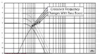
The amount of bass included in recordings varies greatly, and the ability to adjust the amount of bass between songs or albums is useful. Unlike conventional remote bass controls, the MS-WBC doesn't simply increase the level of the amplifier's channels that are connected to the subwoofer. Conventional bass controls adversely affect the crossover between the subwoofer and the midbass or midrange speakers any time they are adjusted. This arrangement causes the bass to sound boomy or muddy when it's boosted, and it draws the listener's attention to the subwoofer's location. (See Figure 5a.)
Figure 5a
line
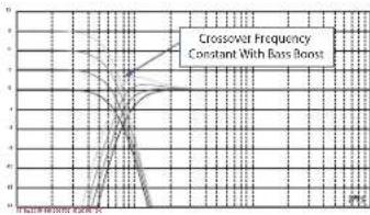
| Bass Boost | Crossover Frequency | | ---------- | ------------------- | | 0 | 0 | | 1 | 1 | | 2 | 2 | | 3 | 3 | | 4 | 4 | | 5 | 5 |The bass-boost filter in the MS-series amplifiers is a shelf filter that boosts or cuts bass below 60Hz but never above 160Hz. The range of adjustment is +/-10dB. Additionally, the bass boost or cut is sent to all the amplifiers with which the control is paired. The bass control works with the crossover filters to ensure that the amplifier sends the proper amount of boost or cut to the subwoofer and the midbass or midrange speakers so the character and apparent location of bass sounds remain constant. See Figure 5b for the performance of the MS-WBC over the conventional bass controls as would appear in Figure 5a.
Figure 5b
line
| Bass Boost Level | Crossover Frequency | | ---------------- | ------------------- | | 0.0000 | 5 |CAUTION: Installation of car-audio components requires experience in performing mechanical and electrical procedures. If you feel you lack the required experience or necessary tools, please have a qualified professional technician install your amplifier.
CAUTION: Before installation, disconnect the negative (−) battery terminal to prevent damage to the unit and to prevent the battery from being drained while you work on the car.
Read this before starting installation!
1) JBL MS-series amplifiers include many features not found on conventional car audio amplifiers. As a result, the setup procedure for JBL MS-series amplifiers is different from that of conventional car audio amplifiers. Carefully read and understand these instructions before attempting installation.
2) At the installation sites, locate and make a note of all fuel lines, hydraulic brake lines, vacuum lines and electrical wiring. Use extreme caution when cutting or drilling in and around these areas.
3) Choose a mounting location for the amplifier inside the passenger or cargo area that will ensure that the amplifier will have no exposure to moisture. Never mount an amplifier outside the car or in the engine compartment.
4) Make sure that there is sufficient air circulation at the mounting location for the amplifier to cool itself.
5) Mount the amplifier securely.
MS-A5001 CONNECTIONS
Power Inputs
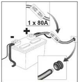
1. +12V Power Input
Connect this input to the vehicle's battery using a minimum size of 8 AWG (8mm ^2 ) wire with a 80A fuse placed within 18 inches (45.7cm) of the positive battery terminal. Use an insulation grommet at every location where the power wire will pass through metal.
2) Remote Turn-On Input (Optional to Connect)
No discrete remote turn-on connection to the MS-A5001 is necessary. If your head unit includes a remote turn-on lead and you wish to connect it, connect it to this terminal.
3) Chassis Ground Input
Using at least 8 AWG (8mm ^2 ) wire, connect this terminal to a nearby point of the vehicle's chassis (sheet metal). Scrape away the paint from the area to ensure a good connection. Do not ground the amplifier to the vehicle's frame.
Audio Inputs
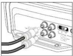
1) Using RCA Outputs
If the unit that precedes this amplifier in the signal chain includes RCA-type output connectors, connect them directly to the amplifier's RCA inputs.
2) Using Speaker-Level Signals
If the equipment that precedes this amplifier doesn't have RCA-type connectors, use the RCA-to-bare-wire adapters included with the amplifier (pictured at right). Connect the signal + to the terminal marked “+” and the signal - to the terminal marked “-”.
Pass-Through Audio Outputs (Full Range)
This amplifier sends input channels 1 and 2 to the corresponding RCA outputs. Using these outputs, you can easily add additional amplifiers. For example: When using the MS-A5001 for a subwoofer, you could use these outputs for a second subwoofer amplifier or a high-frequency amplifier to complete a system. The outputs are full-range, based on the input signal. No high-pass or low-pass filters are applied in the MS-A5001 to these outputs.
Speaker Outputs
Connect each speaker to the amplifier + and - terminals. See page 9 ("Setting the Input Mixer") to learn how to assign the input signals to the output channel. Observe proper polarity when connecting the speakers to the outputs.
1) Single Connection
Connect the + and - terminals to either + and - speaker output terminal. They are connected internally so the signal is available on either terminal.
2) Dual Connection
Connect the + and - of each speaker to one + and - terminal at the amplifier. This arrangement is intended for easy connection of dual subwoofers or a dual voice-coil subwoofer using parallel voice coils.
See pages 12 and 13 for examples of the most common system configurations for this amplifier.
text_image
1 x 80A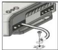
natural_image
Line drawing of a device showing cable connections to ports (no text or symbols)
natural_image
Technical line drawing of a mechanical assembly with a coiled cable and multiple ports (no text or symbols)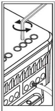
natural_image
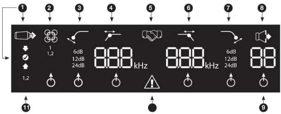
Diagram of a mechanical or electrical component with rotating parts and connecting rods (no text or symbols)MS-A5001 DISPLAY ICONS
text_image
1 2 3 4 5 6 7 8 1 1,2 6dB 12dB 24dB 8.88 kHz 8.88 kHz 6dB 12dB 24dB 8.8 1,2 11 91 Input-Level Settings

Input Setup Mode Active

← Input Sensitivity Too High

← Input Sensitivity Correct

← Input Sensitivity Too Low
5 Pairing Confirmation
Bass Level Controller Pairing*

*MS-WBC Wireless Bass Controller is an optional accessory.
9 Adjustment-Selection Indicator

When lit, the parameter above is selected for adjustment.
② Input-Channel Mixer


Input Mixer Indicates which signal inputs are selected to feed the mono output.
Low-Pass Filter

text_image
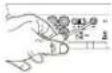
6 800 kHz This setting does not affect pass-through output. 7 SlopeFrequency Protection 6dB 12dB 24dB Amplifier Protection Circuit EngagedHigh-Pass Filter

Slope Frequency

6dB 12dB 24dB


Use as a subsonic filter on the MS-A5001. This setting does not affect pass-through output.
8 Output Gain Adjustment

Output Gain Adjustment Active*

Output Gain Level (0 to 80) *Muted when in "Setup Mode"
11 Channel ID 1,2
Indicates the amplifier channels affected by the row of settings to the right in the display. (As the MS-A5001 is a mono amplifier, only two possible input channels exist.)
Ms-A5001 User CONTROLs
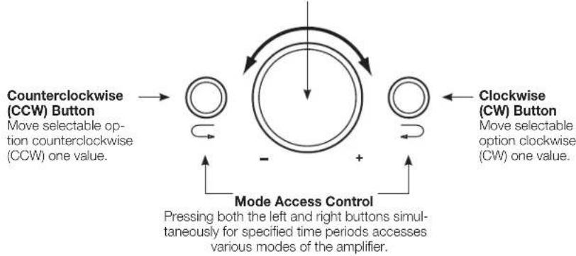
Rotary Encoder
Rotates clockwise (CW) and counterclockwise (CCW). Each detent represents a value increase (CW) or decrease (CCW).
flowchart
graph TD
    A["Clockwise (CCW) Button"] --> B["Move selectable option counterclockwise (CCW) one value."]
    C["Clockwise (CW) Button"] --> D["Move selectable option clockwise (CW) one value."]
    E["Mode Access Control"] --> F["Pressing both the left and right buttons simultaneously for specified time periods accesses various modes of the amplifier."]
    G["->"] --> H["->"]
    I["->"] --> J["->"]
    K["->"] --> L["->"]
    M["->"] --> N["->"]
    O["->"] --> P["->"]
    Q["->"] --> R["->"]
    S["->"] --> T["->"]
    U["->"] --> V["->"]
    W["->"] --> X["->"]
    Y["->"] --> Z["->"]
Ms-A5001 settings Guide
INITIAL SETUP
Activating the Controls
Press both CCW and CW buttons at the same time for less than three seconds, and release the buttons to activate the controls. The adjustment-selection indicator will light up. Use the CCW and CW buttons to move the indicator to the parameter that you wish to adjust. After you've made your adjustments, and the controls have been inactive for more than 30 seconds, the selection-indicator light will go out, and the controls will become deactivated to prevent unintentional adjustment of the amplifier's controls.

natural_image
Illustration of hands installing or adjusting a device with a grid and circular components (no text or symbols visible)Setting the Input Mixer

1
1,2
Once the controls are active, press the CW or CCW button until the input mixer is selected for channels 1 and 2. Turn the rotary control to select the input connector(s) that will feed output channels 1 and 2.

See "System Diagrams" on pages 12 and 13 for practical examples.
Setting the Input Level, and Enabling or Disabling Signal-Sensing Turn-On BEFORE YOU BEGIN
If the factory-installed system to which you have connected your MS-series amplifier shows a "speaker disconnected" error message or fails to provide an output signal, move the input-level switch to the Hi2 position. You may need to turn the vehicle or the factory-installed head unit off and then back on to reset the error message.
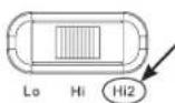
NOTE: DO NOT USE THE Hi2 SETTING WITH THE RCA OUTPUTS OF AFTERMARKET HEAD UNITS!

To Set the Input Level:
- Move the input-level control to the Hi position (or Hi2 if you are connecting to a factory-installed system with open-circuit protection).
- Set the bass, treble, balance and fader controls on your head unit to the center (or flat) positions. Set "loudness" to off. Defeat any sound-enhancement settings (such as DSP, surround sound or EQ).
- Insert the setup CD into your head unit and verify that the CD is playing.
- Enter the setup mode by pressing CW and CCW buttons simultaneously for more than three seconds until the input-level adjustment icon illuminates. The amplifier's output will be muted (output-level indicator will show " — —" in the display).
- Turn the head unit's volume control all the way up (to maximum output).
- Using a small screwdriver on the level-adjustment dial next to the input switch, adjust the input-level control up or down while watching the icons on the amplifier's display panel.
If the green "up" arrow If the red "down" arrow lights up.
- Icon is lit, turn the control clockwise until the icon lights up. - Icon is lit, turn the control counterclockwise until the icon

Note: If turning the control fully clockwise doesn't cause the level control to the "Lo" position and try again.
√ icon to light, move the input-
Once the ⚙️ icon lights up, stop adjusting. Repeat the procedure for the input-level control on the other channels. When both check marks light up, you have properly set the input levels for each channel pair.
To Enable or Disable Signal-Sensing Turn-On:
-
While in setup mode, enable or disable signal-sensing turn-on by turning the Rotary Control clockwise or counterclockwise to select "SEn On" or "SEn OFF" in the display. If you have connected a remote turn-on lead, set to "SEn OFF."
-
Turn the volume control on your head unit down and remove the setup CD. If you miss or circumvent this step, the audio system will reproduce a loud test signal that could damage your speakers when you exit the setup mode.
-
Press and release the CW and CCW buttons simultaneously to exit the setup mode.
-
Do not adjust the input-level controls further. Use the output-level control to balance the channel levels and to "tune" the system.
Mode Function
| SEn On Signal Sensing is ON |
| SEn OFF Signal Sensing is OFF |
SETTING THE FILTERS (CROSSOVERS)
There are 98 selectable frequencies for the low-pass and high-pass filter settings. The selectable frequencies are detailed in the table to the right.
Getting to the Crossover Settings
Press both CCW and CW buttons at the same time for less than three seconds; release the buttons to activate the controls. Use the CCW and CW buttons to navigate to your preferred crossover-adjustment parameter.
How to Set a High-Pass Filter
Navigate to the high-pass filter frequency parameter. Using the rotary encoder, select the desired cutoff frequency. Then navigate to the high-pass filter slope parameter and, using the rotary encoder, select the desired filter slope.
High-Pass Example
Use the CW and CCW buttons to navigate to the low-pass frequency parameter and set to "OFF."

Available Crossover Frequency Settings
| 20.0Hz | 40.0Hz | 60.0Hz | 80.0Hz | 100Hz |
| 21.0Hz | 41.0Hz | 61.0Hz | 81.0Hz | 101Hz |
| 22.0Hz | 42.0Hz | 62.0Hz | 82.0Hz | 102Hz |
| 23.0Hz | 43.0Hz | 63.0Hz | 83.0Hz | 103Hz |
| 24.0Hz | 44.0Hz | 64.0Hz | 84.0Hz | 104Hz |
| 25.0Hz | 45.0Hz | 65.0Hz | 85.0Hz | 105Hz |
| 26.0Hz | 46.0Hz | 66.0Hz | 86.0Hz | 106Hz |
| 27.0Hz | 47.0Hz | 67.0Hz | 87.0Hz | 107Hz |
| 28.0Hz | 48.0Hz | 68.0Hz | 88.0Hz | 108Hz |
| 29.0Hz | 49.0Hz | 69.0Hz | 89.0Hz | 109Hz |
| 30.0Hz | 50.0Hz | 70.0Hz | 90.0Hz | 110Hz |
| 31.0Hz | 51.0Hz | 71.0Hz | 91.0Hz | 115Hz |
| 32.0Hz | 52.0Hz | 72.0Hz | 92.0Hz | 120Hz |
| 33.0Hz | 53.0Hz | 73.0Hz | 93.0Hz | 125Hz |
| 34.0Hz | 54.0Hz | 74.0Hz | 94.0Hz | 130Hz |
| 35.0Hz | 55.0Hz | 75.0Hz | 95.0Hz | 135Hz |
| 36.0Hz | 56.0Hz | 76.0Hz | 96.0Hz | 140Hz |
| 37.0Hz | 57.0Hz | 77.0Hz | 97.0Hz | OFF |
| 38.0Hz | 58.0Hz | 78.0Hz | 98.0Hz | |
| 39.0Hz | 59.0Hz | 79.0Hz | 99.0Hz |
How to Set a Low-Pass Filter
Navigate to the low-pass filter frequency parameter and, using the rotary encoder, select the desired cutoff frequency. Then navigate to the low-pass filter slope parameter and, using the rotary encoder, select the desired filter slope.
Low-Pass Example
Use the CW and CCW buttons to navigate to the high-pass frequency parameter and set to "OFF."
How to Set a Band-Pass Filter
Band-Pass Example
To build a proper band-pass filter, the low-pass frequency must be greater than the high-pass frequency. The MS-A5001 will not allow you to set the low-pass filter frequency to a lower value than the high-pass filter frequency. To enable


a band-pass filter, first select the high-pass filter frequency and slope as indicated above. Next, select the low-pass filter frequency and slope. Once the settings are complete, the controls will time out after 15 seconds.
OUTPUT LeveLs
Setting the Output Level

Use the output-level control to adjust the balance between the subwoofer and the full-range speakers, between the front and rear speakers, or between the midrange, mid-bass or tweeters in a bi-amped or tri-amped (all active) system. The output level is adjustable in 0.5dB increments, with a display of 80 indicating maximum output. The lowest setting will mute the output and “_” will show in the display.
To set the output level, press the CW or CCW buttons to highlight the output-level parameter for adjustment, and turn the rotary controller to adjust the output level.
WireLess BAss CONTrol
Overview MS-WBC
The MS-WBC wireless bass control (sold separately) is battery-powered; it also includes a +12V plug that can be connected to a +12V source in your vehicle. The MS-WBC transmits a signal only when the control is rotated. The amplifier(s) must be on to receive and respond to the control. Adjustments made to the control when the amplifier(s) are off aren't recognized.

How to Pair the MS-WBC Wireless Bass Control with the MS-A5001
The optional MS-WBC wireless bass controller must be paired to the amplifier in order to be used. When the amplifier is first turned on, it is not paired with any controller.
Press and hold both CCW and CW buttons simultaneously for more than three seconds and the amplifier will enter Setup mode. Continue pressing the buttons for four more seconds until the pairing indicator is illuminated. Release the CCW and CW buttons.
Pairing must occur within 15 seconds. The time remaining is indicated at the far right of the display. Turn the knob on the bass controller during this 15-second period. The amplifier will recognize the controller, and the controller will automatically pair the two together.
After a successful pairing, the upper high-pass filter digits will display the bass controller version number for 3 seconds. Then the amplifier will return to the normal (Run) mode.
If a valid pairing has not occurred, the amplifier will remain unpaired. After the 15-second countdown, the amplifier will return to the setup mode.
If your system includes several MS-series amplifiers, pair them one at a time. Once all the amplifiers are paired and have returned to the normal (Run) mode, turn the knob to synchronize all of the amplifiers.

flowchart
graph TD
    A["Hand holding device"] --> B["Sh handshake"]
    B --> C["Circle with clock icon"]
sYsTeM diAGrAMs

text_image
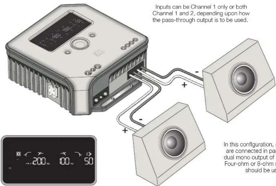
Inputs can be Channel 1 only or both Channel 1 and 2, depending upon how the pass-through output is to be used.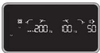
text_image
200 100 50Example of filter and input settings for this configuration
In this configuration, a single subwoofer is connected at one of the MS-A5001 outputs. A 4-ohm or 2-ohm subwoofer can be used.
text_image
Inputs can be Channel 1 only or both Channel 1 and 2, depending upon how the pass-through output is to be used. In this configuration, s are connected in par dual mono output of f Four-ohm or 8-ohm s should be usExample of filter and input settings for this configuration
In this configuration, subwoofers are connected in parallel at the dual mono output of MS-A5001. Four-ohm or 8-ohm subwoofers should be used.
sYsTeM diAGrAMs (dvC sUBs)
text_image
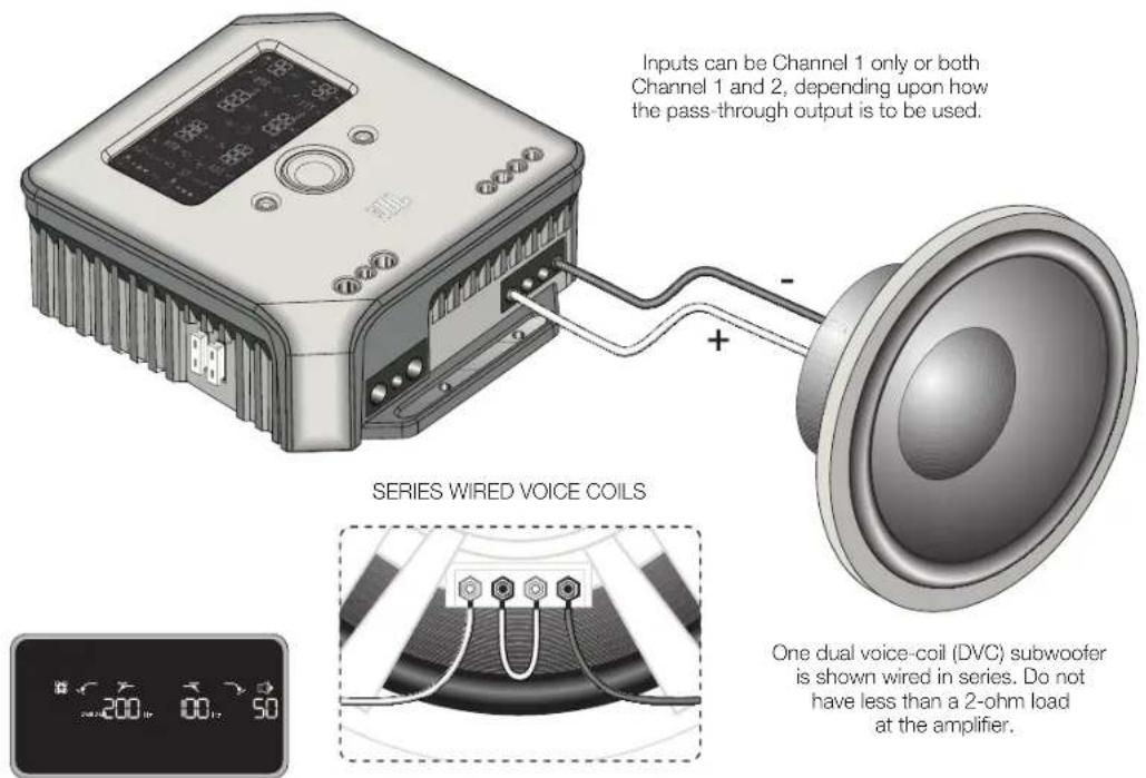
Inputs can be Channel 1 only or both Channel 1 and 2, depending upon how the pass-through output is to be used. + - SERIES WIRED VOICE COILS One dual voice-coil (DVC) subwoofer is shown wired in series. Do not have less than a 2-ohm load at the amplifier.Example of filter and input settings for this configuration
One dual voice-coil (DVC) subwoofer is shown wired in series. Do not have less than a 2-ohm load at the amplifier.
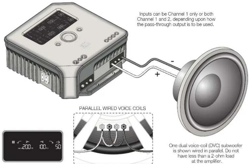
text_image
Inputs can be Channel 1 only or both Channel 1 and 2, depending upon how the pass-through output is to be used. PARALLEL WIRED VOICE COILS One dual voice-coil (DVC) subwoofer is shown wired in parallel. Do not have less than a 2-ohm load at the amplifier.Example of filter and input settings for this configuration
One dual voice-coil (DVC) subwoofer is shown wired in parallel. Do not have less than a 2-ohm load at the amplifier.
CALCULATING SPEAKER LOADS
Use these formulas to calculate total series or parallel resistance of multiple speakers or voice coils on the MS-A5001 amplifier. "R" with a number denotes each nominal voice-coil impedance (such as R_1 and R_2 ). R_t is the total combined nominal impedance presented to the amplifier. Never connect loads below a total of 2 ohms.

text_image
JBL by HARMANSeries Connection Parallel Connection

text_image
Rt = R1 + R2 + R3...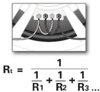
text_image
Rt = 1 \frac{1}{R_1} + \frac{1}{R_2} + \frac{1}{R_3} ...SPECIFICATIONS
Power output
CEA® 2006
500W RMS x 1 channel @ 4 ohms
500W RMS x 1 channel @ 2 ohms
Bridged mode
Signal-to-noise ratio
106dB
Frequency response
20-270Hz
Maximum input sensitivity
100mV
Maximum input voltage
20V
Dimensions (L x W x H)
7-3/16" × 8-1/4" × 2-3/4"
183mm × 210mm × 70mm
Weight
Beauty carton dimensions
13-15/16" × 11-9/16" × 10-5/16"
354mm × 294mm × 264mm
Gross weight (with beauty carton)

© 2010 Harman International Industries, Incorporated. All rights reserved. JBL is a trademark of Harman International Industries, Incorporated, registered in the United States and/or other countries. CEA is a registered trademark of the Consumer Electronics Association. Features, specifications and appearance are subject to change without notice.
HARMAN
Harman Consumer, Inc.
8500 Balboa Boulevard
Northridge, CA 91329 USA