
cnPilot r190 - Access Point Cambium Networks - Free user manual and instructions
Find the device manual for free cnPilot r190 Cambium Networks in PDF.


| Product Type | Indoor/Outdoor Dual-Band Access Point |
| Wi-Fi Standards | IEEE 802.11a/b/g/n/ac Wave 2 |
| Frequency Bands | 2.4 GHz and 5 GHz |
| MU-MIMO | Yes (2x2:2 per band) |
| Maximum Data Rate | 867 Mbps (5 GHz) + 300 Mbps (2.4 GHz) |
| Power Supply | PoE (802.3af/at) |
| Power Consumption | 13 W (max) |
| Dimensions (W x D x H) | 200 mm x 200 mm x 45 mm |
| Weight | 0.7 kg |
| Ethernet Ports | 1 x 10/100/1000 Mbps (PoE in) |
| Management | Web UI, SNMP, CLI, Cloud (cnMaestro) |
| Mounting | Wall or ceiling mount (bracket included) |
| Operating Temperature | -20°C to 60°C |
| Ingress Protection | IP66 (outdoor rated) |
| Safety Certifications | FCC, CE, IC, UL |
| Warranty | 1 year (limited) |
| Maintenance and Cleaning | Wipe with soft dry cloth; avoid liquids |
| Spare Parts and Reparability | No user-serviceable parts; contact support for repairs |
Frequently Asked Questions - cnPilot r190 Cambium Networks
User questions about cnPilot r190 Cambium Networks
0 question about this device. Answer the ones you know or ask your own.
Ask a new question about this device
Download the instructions for your Access Point in PDF format for free! Find your manual cnPilot r190 - Cambium Networks and take your electronic device back in hand. On this page are published all the documents necessary for the use of your device. cnPilot r190 by Cambium Networks.
USER MANUAL cnPilot r190 Cambium Networks
natural_image
Exterior view of a multi-level surveillance camera mounted on an elevated highway, with vehicles in the background (no signage or text visible)
Cambium Networks™

natural_image
Aerial night view of a town nestled on rocky hills with a river in the background (no visible text or symbols)
natural_image
Young girl in blue shirt using tablet at a classroom (no visible text or symbols)
natural_image
Overhead view of a group of people seated at a table in a casual café setting, with no visible text or signage.
natural_image
Desert landscape with oil rig and scattered vegetation under a dramatic cloudy sky (no text or symbols visible)USER GUIDE
cnPilot Home Router
System Release 4.8

natural_image
Aerial view of a coastal industrial or port facility with ships, storage tanks, and turquoise waters under a blue sky with clouds (no visible text or symbols)
natural_image
Man working at a wooden mill bench with a laptop and paper nearby (no visible text or symbols)Reservation of Rights
Cambium reserves the right to make changes to any products described herein to improve reliability, function, or design, and reserves the right to revise this document and to make changes from time to time in content hereof with no obligation to notify any person of revisions or changes. Cambium recommends reviewing the Cambium Networks website for the latest changes and updates to products. Cambium does not assume any liability arising out of the application or use of any product, software, or circuit described herein; neither does it convey license under its patent rights or the rights of others. It is possible that this publication may contain references to, or information about Cambium products (machines and programs), programming, or services that are not announced in your country. Such references or information must not be construed to mean that Cambium intends to announce such Cambium products, programming, or services in your country.
Copyrights
This document, Cambium products, and rd Party software products described in this document may include or describe copyrighted Cambium and other rd Party supplied computer programs stored in semiconductor memories or other media. Laws in the United States and other countries preserve for Cambium, its licensors, and other rd Party supplied software certain exclusive rights for copyrighted material, including the exclusive right to copy, reproduce in any form, distribute and make derivative works of the copyrighted material. Accordingly, any copyrighted material of Cambium, its licensors, or the 3d Party software supplied material contained in the Cambium products described in this document may not be copied, reproduced, reverse engineered, distributed, merged or modified in any manner without the express written permission of Cambium. Furthermore, the purchase of Cambium products shall not be deemed to grant either directly or by implication, estoppel, or otherwise, any license under the copyrights, patents or patent applications of Cambium or other 3rd Party supplied software, except for the normal non-exclusive, royalty free license to use that arises by operation of law in the sale of a product.
Restrictions
Software and documentation are copyrighted materials. Making unauthorized copies is prohibited by law. No part of the software or documentation may be reproduced, transmitted, transcribed, stored in a retrieval system, or translated into any language or computer language, in any form or by any means, without prior written permission of Cambium.
License Agreements
The software described in this document is the property of Cambium and its licensors. It is furnished by express license agreement only and may be used only in accordance with the terms of such an agreement.
High Risk Materials
Cambium and its supplier(s) specifically disclaim any express or implied warranty of fitness for any high-risk activities or uses of its products including, but not limited to, the operation of nuclear facilities, aircraft navigation or aircraft communication systems, air traffic control, life support, or weapons systems (“High Risk Use”).
This product is not restricted in the EU. Any High Risk is unauthorized, is made at your own risk and you shall be responsible for any and all losses, damage or claims arising out of any High-Risk Use.
Contents
Contents 3.
About This User Guide 7
Declaration of Conformity 8.
Part 15 FCC Rules.8
Class B Digital Device or Peripheral 8.
GNU GPL Information 8
Conventions, warnings, Attention, and notes 8.
Conventions 8
Warnings 9
Attention 9
Notes 9
Chapter 1: Product Description..10.
LED Indicators and interfaces (r190V/r190W/r200/r200P/r195W/r195P) 10
LED Indicators and interfaces (r190V/r190W/r200/r200P). 11
LED indicators and interfaces (r201/r201P/r201W) 13
Hardware installation 14
Configuring the router 14
New in this release 15
cnPilot Home Router specifications 15
Chapter 2: Basic Settings
Web management interface 16
EZ UI 16
Logging in from the LAN port 19
Logging in from the WAN port 20
Parental Control 20
Accessing and Configuring cnPilot Home Router via cnMaestro 22
Managing device via cnMaestro 22
Performing speed test 23
Chapter 3: Advanced Configuration 24
Two-Level Management.24
Setting the time zone..25
Status 26.
Configuring the Internet connection.30.
Custom factory default configuration.32
Configuring as Range Extender / Wi-Fi Repeater.36.
Repeater configuration.36
Base AP configuration for repeater mode.36
Repeater AP configuration..37.
Network 42
WAN 42
IPv6 address configuration..55
LAN 60
Wireless .69
Basic .69
Wireless security 72
WMM 74
WDS 75
WPS 76
Station Info 78
Advanced 79
Parental control 80
SIP 82
SIP Settings 82
Parameters and Settings 82
Adding one Dial Plan 83
Dial Plan Syntactic 83
Blacklist 84
Call Log 85
VoIP QoS 87
FXS1 87
SIP Account 87
Audio Configuration 89
Supplementary Service Subscription 90
Advanced 92
Preferences 94
Regional 94
Features and Call Forward 96
Miscellaneous 97
FXS2 98
Voice calls 98
Making a call 98
Direct IP calls 98
Call hold 99
Blind transfer 99
Attended transfer 99
Conference 99
Security 100
Filtering Setting 100
Content Filtering 101
Application 102
UPnP 102
IGMP 102
Storage 102
Disk Management 102
FTP Setting 104
Smb Setting 105
Administration 105
Management 106
Firmware upgrade 111
Provision 112
SNMP 115
TR-069 115
Diagnosis 133
Operating Mode 136
System Log 136
Logout 136
Reboot 137
Chapter 4: Troubleshooting 138
Configuring PC to get IP Address automatically.138
Cannot connect to the Web GUI.138
Forgotten Password 138
cnMaestro On-boarding troubleshooting 138
Appendix: Third Party Software 141
Appendix: Part Numbers.... 141
Appendix: Part Numbers 142
Part Numbers for cnPilot r195P Home Router 142
Part Numbers for cnPilot r195W Home Router 142
Part Numbers for cnPilot r200, r200P Home Routers 143
Part Numbers for cnPilot R201, R201P Home Routers 143
Part Numbers for r201W Home Router 144
Part Numbers for cnPilot r190W Home Router 144
Part Numbers for cnPilot r190V Home Router 144
Glossary 145
Cambium Networks 149
About This User Guide
This manual provides basic information about how to install and deploy the cnPilot Home Routers. For remote configuration and deployment, an Internet connection is required.
The cnPilot Home Router is a managed device (that yet can act as a stand-alone router if desired). In addition to Wi-Fi, this product provides high quality voice calls (VoIP models only) as well as the optional ability to power Cambium Networks ePMP series Subscriber Module(SM) or the PMP450 series SM by supporting Cambium Networks (Canopy) PoE. For voice calls, the product is fully compatible with the SIP industry standard and can interoperate with many other SIP devices and softwares.

natural_image
Exterior view of multiple wireless routers and WiFi units (no text or symbols visible)This guide contains the following chapters:
• Chapter 1: Product Description
• Chapter 2: Basic Settings
• Chapter 3: Advanced Configuration
• Chapter 4: Troubleshooting
Declaration of Conformity
Part 15 FCC Rules
This device complies with Part 15 of the FCC Rules. Operation is subject to the following two conditions:
• This device may not cause harmful interference, and
- This device must accept any interference received, including interference that may cause undesired operation.
Class B Digital Device or Peripheral
This equipment has been tested and found to comply with the limits for a Class B digital device, pursuant to Part 15 of the FCC Rules. These limits are designed to provide reasonable protection against harmful interference in a residential installation. This equipment can generate, use and radiate radio frequency energy. If not installed and used in accordance with the instruction manual, may cause harmful interference to radio communications. However, there is no guarantee that interference does not occur in an installation.

Note
Changes or modifications not expressly approved by the party responsible for compliance could void the user's authority to operate the equipment.
If this equipment does cause harmful interference to radio or television reception, which can be determined by turning the equipment OFF and ON, the user is encouraged to try to correct the interferences by one or more of the following measures:
- Reorient or relocate the receiving antenna.
- Increase the separation between the equipment and receiver.
- Connect the equipment into an outlet on a circuit different from that to which the receiver is connected.
- Consult the dealer or an experienced radio/TV technician for help.
GNU GPL Information
cnPilot Home Router firmware contains third-party software under the GNU General Public License (GPL). Refer the GPL for exact terms and conditions of the license. Important regulatory information.
Conventions, warnings, Attention, and notes
The following describes how conventions, warnings, attention, and notes are used in this document and in all documents of the Cambium Networks document set.
Conventions
The following convention is used throughout this User Guide:
cnPilot Home Router: Cambium cnPilot Home and Small Business Wireless Router family (cnPilot r190V/r190W/r195W/r195P/r200/r200P/r201/r201P/r201W Home Router models)
Warnings
Warnings precede instructions that contain potentially hazardous situations. Warnings are used to alert the reader to possible hazards that could cause loss of life or physical injury. A warning has the following format:

Warning
Warning text and consequence for not following the instructions in the warning.
Attention
Attention precedes instructions and are used when there is a possibility of damage to systems, software, or individual items of equipment within a system. However, this damage presents no danger to personnel. Attention has the following format:

Attention
Attention text and consequence for not following the instructions.
Notes
A note means that there is a possibility of an undesirable situation or provides additional information to help the reader understand a topic or concept. A note has the following format:

Note
Note text.
Chapter 1: Product Description
This chapter contains the following topics:
• LED Indicators and interfaces (r190V/r190W/r200/r200P/r195W/r195P)
• LED Indicators and interfaces (r190V/r190W/r200/r200P)
• LED Indicators and interfaces (r201/r201P/r201W))
- Hardware installation
- Configuring the router
- New in this release
LED Indicators and interfaces (r190V/r190W/r200/r200P/r195W/r195P)

Figure 1: cnPilot LED indicators
| LED Status | Explanation | |
| 2.4G | Blinking (Green) | 2.4G is connected, and there is data transmitted |
| On (Green) Wireless access point is ready | ||
| Off 2.4G WiFi off or system is powered off | ||
| 5G Blinking | (Green) 5G is connected, and there is data transmitted | |
| On (Green) Wireless access point is ready | ||
| Off 5G WiFi off or system is powered off | ||
| WAN Blinking | (Green) There is data being transmitted | |
| On (Green) Network is connected (physical connection established), no data transmission | ||
| Off System is powered off or the network port is not connected to the network device | ||
| LAN (1-4) | Blinking (Green) | There is data being transmitted |
| On (Green) Network | work is connected (physical connection established), no data transmission | |
| Off System is powered off or the network port is not connected to the network device | ||
| POWER On (Green) System is powered ON | ||
LED Indicators and interfaces (r190V/r190W/r200/r200P)
Front Panel of cnPilot r200/r200P Home Router

Table 1: cnPilot r200/r200P LED indicators
| LED Status | Explanation | |
| Phone1/2 B | linking (Green) Not | registered |
| On (Green) | Registered | |
| LAN 1/2/3/4 | On (Green) | Port is connected at 100 Mbps |
| Off | The port is disconnected | |
| Blinking (Green) Transmitting data | ||
| WAN | On (Green) | Port is connected with 100 Mbps |
| Off | The port is disconnected | |
| Blinking (Green) Blinks while transmitting data | ||
| POWER | On (Green) | The router is powered on and running normally |
| Off | The router is powered off | |
| WLAN | On (Green) | Wireless access point is ready |
| Blinking (Green) Blinks while wireless traffic goes through | ||
Front Panel of cnPilot r190V/r190W Home Router
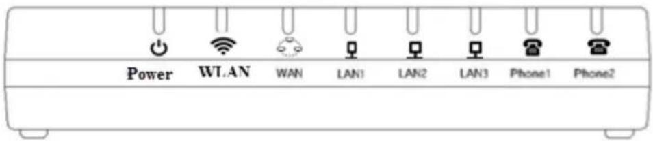
Table 2: cnPilot r190V/r190W LED indicators
| LED Status | Explanation | |
| Power On Power is ON/Device is ready | ||
| WAN/LAN On Link is Up | ||
| FXS Off Unregistered | ||
Rear Panel of cnPilot r190V/r190W/r200/r200P Home Router

Table 3: cnPilot r190V/r190W/r200/r200P interfaces Home Routers
| Interface | Description |
| POWER | Connector for a power adapter |
| Phone1/2 | ATA Analog phone connector |
| USB | USB interface |
| WAN | Connector for accessing the Internet |
| LAN (1/2/3/4) | Connectors for local networked devices |
LED indicators and interfaces (r201/r201P/r201W)
Front Panel of cnPilot r201/r201P/r201W Home Router

Table 4: cnPilot r201/r201P/r201W LED indicators
| LED Status Explanation | ||
| USB On (Green) Connected | ||
| 2.4G/5G | Blinking (Green) The port is passing data | |
| On (Green) The port is connected | ||
| WAN Off The | port is disconnected | |
| Blinking (Green) The data is transmitting | ||
| On (Green) The port is connected at 100/1000 Mbps | ||
| LAN 1/2/3/4 Off The port is disconnected | ||
| POWER ON (Green) Router is powered on and running normally | ||
Table 5: cnPilot r201/r201P/r201W interfaces
| Interface | Description |
| ON/OFF | Power Switch |
| POWER | Connector for a power adapter |
| USB | USB interface |
| LAN (1/2/3/4) | Connectors for local networked devices |
| WAN | Connector for accessing the Internet |
Hardware installation
Before configuring the router, refer the following procedure for instructions on connecting the cnPilot Home Router into the network.

Note
Ensure that the equipment is operated in accordance with the applicable regulations. It is operator's responsibility to ensure that the latest Firmware updates are applied. Download the latest Firmware and install it in the device before deploying the cnPilot Home Router. The latest Firmware is available on Cambium Networks Support Site and the instructions for installing the Firmware are provided in the Firmware upgrade section.
Configuring the router
To configure the router, perform the following steps:
- Connect analog phone to ATA Port with an RJ11 cable.
- Connect the WAN port to the Internet via your network's modem/switch/router/ADSL equipment using an Ethernet cable.
- Connect one end of the power cord to the power port of the device and the other end to the wall outlet.
- Press ON/OFF button to power on the router (if available).
- Check the Power, WAN, and LAN LEDs to confirm network connectivity.

Warning
Do not attempt to use unsupported power adapters and do not remove power during configuring or updating the cnPilot Home Router device. Using other power adapters may damage the cnPilot Home Router and will void the manufacturer warranty.

Warning
Changes or modifications not expressly approved by the party responsible for compliance can void the user's authority to operate the equipment.
This equipment has been tested and found to comply with the limits for a Class B digital device, pursuant to Part 15 of the FCC Rules. These limits are designed to provide reasonable protection against harmful interference in a residential installation. This equipment generates, uses and can radiate radio frequency energy and, if not installed and used in accordance with the instructions, may cause harmful interference to radio communications. However, there is no guarantee that interference will not occur in a particular installation.
If this equipment does cause harmful interference to radio or television reception, which can be determined by turning the equipment off and on, the user is encouraged to try to correct the interference by one or more measures.
New in this release

Note
This product meets the UL/cUL 62368 /IEC 62368 edition 2 specification.
cnPilot Home Router specifications
| Features r19 | 90V r190V | W r200P | r200 r201 | r201P r201W r195 | W r195P | |||
| WAN 1xFE | 1xGE | |||||||
| LAN 3xFE | 4xFE | 4xGE | ||||||
| Wi-Fi2.4GHz | 2X2 802.11 b/g/n | |||||||
| Wi-Fi5GHz | X | 2X2 5GHz 802.11ac(867 Mbps) | ||||||
| USB | X | X | 1X USB 2.0 | X | 1 USB2.0 Host Port for shared storage | |||
| VoIP | 2 × FXS1 | X | 2 × FXS1 | X X | 2xFXS | 2 | ||
| Cambium PoE Out (30V) | X | Yes3 | X X | Yes | 4 | X | Yes | |
| Power Adapter | 12V/1A | 5V/1A | 12V/3A | 12V/2A | 12V/2A | 12V/3A | 12V/2A | 12V/1A |
| cnMaestro Managed | √ | |||||||
| RAM | 128MB | 64MB | 256MB | 64MB | 128MB | |||
| Flash | 16MB | 32MB | ||||||
Chapter 2: Basic Settings
This chapter contains the following topics:
• Web management interface
- Accessing and Configuring cnPilot Home Router via cnMaestro
Web management interface
cnPilot Home Routers feature a web browser-based interface that may be used to configure and manage the device. See below for information.

Note
By default, only https access is allowed. Any attempt to access the device UI over http will now be automatically redirected to https.
EZ UI
cnPilot Home Routers provides an additional simplified management interface for home users. The home users can connect to any of the LAN port of the device and type www.mywifiap.com in the browser to access the EZ UI.
Home users needs to provide the default Basic User credentials as useradmin/admin.

Note
Check with your ISP if the basic user credentials are changed to improved security.
Figure 2: EZ UI

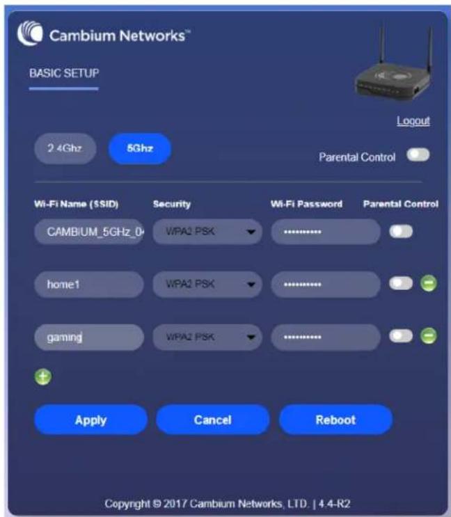
The ISP allows the home user to access the EZ UI through a wireless client connected to the cnPilot Home Router. Using the EZ UI, the user can easily change the basic device configurations such as Wi-Fi names, Wi-Fi passwords and parental control.
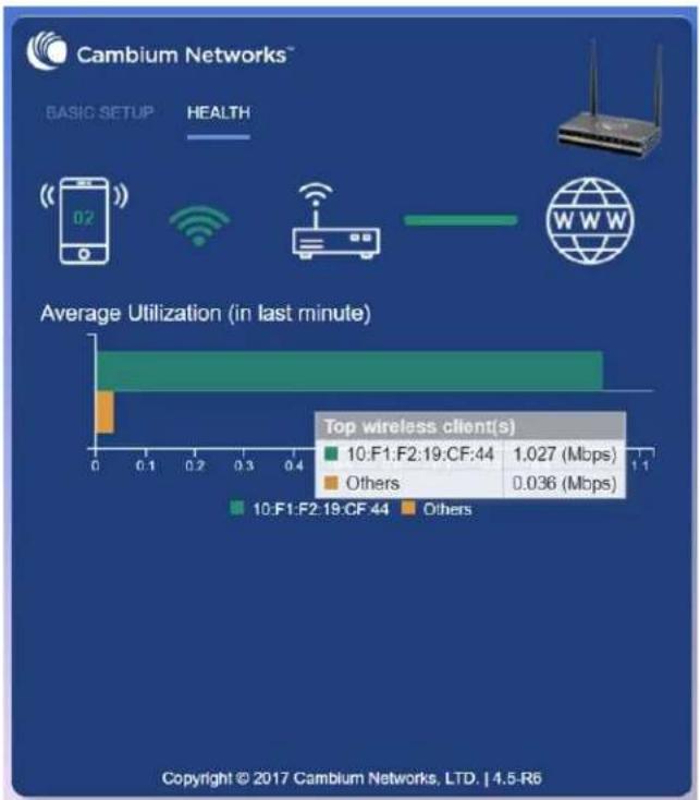
bar
Average Utilization (in last minute) | Client | Average Utilization (in last minute) | |---|---| | 10:F1:F2:19:CF:44 | 1.027 (Mbps) | | Others | 0.036 (Mbps) |Chapter 2: Basic Settings 17
The EZ-UI now has a new HEALTH tab, which shows the overall health of the home network. It helps isolate problems if any and provide basic insight into the bandwidth utilization.

Note
An option is provided to disable EZ-UI and revert to the conventional Basic User mode UI.
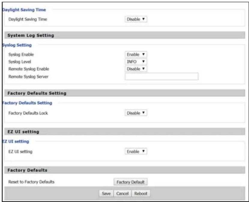
EZ UI Co-branding
The user can add the customized new logo alongside to Cambium Networks logo in the EZ-UI page. To upload customized logo, under EZ UI Logo Upload, browse and select the logo, and then click Upload. The following Figure 3 describes the uploading of the new logo. To revert back to the default logo setting, select Disable for EZ UI Upload Setting. To customize the EZ UI, download EZ-UI cambium co-brand.css file from Cambium Networks Support site and modify as required.

Figure 3: EZ UI Co-branding
Logging in from the LAN port
Ensure that your PC is connected to the router's LAN port correctly.

Note
You may either set up your PC to get an IP dynamically from the router or set up the IP address of the PC to be the same subnet as the default IP address of router is 192.168.11.1. For more information, refer Configuring PC to get IP Address automatically.

Note
Management access from a wireless client is enabled by default.
Open a web browser on your PC and type https://192.168.11.1/. The following window appears to enter Username and Password.
Figure 4: Login Prompt - LAN Port
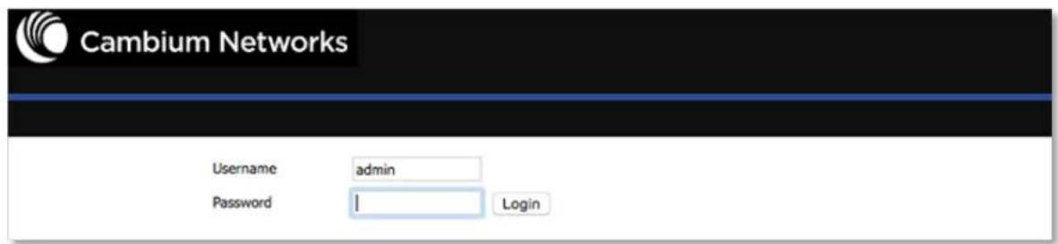
For administrator mode operation, type admin/admin for Username/Password and click Login to begin the configuration. For user mode operation, type user/user for Username/Password and click Login to begin configuration.

Note
If you are unable to access the web configuration. For more information, refer to Configuring PC to get IP Address automatically section.
The web management interface automatically logs out the user after five minutes of inactivity.
Logging in from the WAN port

Note
By default, the web access from WAN interface is disabled from 4.3.3 release onwards for security reasons for cnPilot r190/r200/r201. Users can enable this from GUI (via LAN client).
For r195W WAN access is enabled by default, however login is not allowed if default admin credentials are configured on the device. cnPilot r195W Home Router UI can be accessed via WAN by setting non default admin credentials.
Ensure that your PC is connected to the router's WAN port correctly.
Obtain the IP addresses of WAN port using Voice prompt or by logging into the device web management interface via a LAN port and navigating to Status page.
Open a web browser on your PC and type https://
Figure 5: Login Prompt - WAN Port

For administrator mode operation, type admin/admin for Username/Password and click Login to begin configuration. For user mode operation, type user/user for Username/Password and click Login to begin configuration.

Note
If you fail to access to the web configuration. For more information, refer to Troubleshooting section.
The web management interface automatically logs out the user after five minutes of inactivity.
Parental Control
cnPilot Home Routers provide parental control feature for home users. Parental control allows home users to restrict access to unlawful/adult content over their WiFi network. This feature is based on external DNS filtering (like OpenDNS).
Parental control feature enable/disable is only available via EZ UI. To enable parental control feature, tap Parental Control button.

Configure cnPilot Home Router with the DNS server IP(s) provided by the parental control service provider.

Chapter 2: Basic Settings 21
Parental control feature can be applied only to a specific WiFiName/SSID while the other SSIDs can be free from any such restrictions. Once the device is setup for Parental control service, any DNS request from its clients will be forwarded to the external DNS servers configured for filtering/restricting the content.
When parental control is enabled, it is applied to all the LAN clients and it cannot be disabled for specific LAN ports.
Accessing and Configuring cnPilot Home Router via cnMaestro
cnMaestro is the Cambium Networks next generation network management system which is the recommended for managing Cambium Networks cnPilot Home Routers. As Cambium Networks develops new features, you may find the latest information on operating these features at the Cambium Networks Community Forum.
Register at Cambium Networks support forum for instructions, discussions, and helpful tips on managing cnPilot Home Routers.
Managing device via cnMaestro
cnMaestro is a suite of cloud-based tools for network management: inventory management, onboarding devices, daily operations and maintenance. cnMaestro offers full visibility across the entirety of a network.
Preparing the device
The following are the prerequisites to prepare the device:
- Power on the cnPilot Home Router and configure the IP Address using either the DHCP or Static mode.
- Check for the Internet connectivity. This is required, as the device needs to communicate with the cnMaestro Server hosted in the AWS.
- Allow the IP Addresses of the devices in the Firewall Server using an ACL. Also, enable the protocols like HTTP/HTTPS and SSL.
This is required as the device communicates with the cnMaestro Server using web sockets and for security reasons SSL certificates are exchanged between the device and the cnMaestro Serve - Devices with default configuration can configure to https://cloud.cambiumnetworks.com. Users may choose to configure alternateOn-Premises IP address/URL.

Note
In 4.6 release, the following options are introduced under cnMeastro Configuration page:
- IPv6 Preferred - if a router is deployed in a mixed environment (IPv4 and IPv6), this option allows user to onboard their device using IPv6
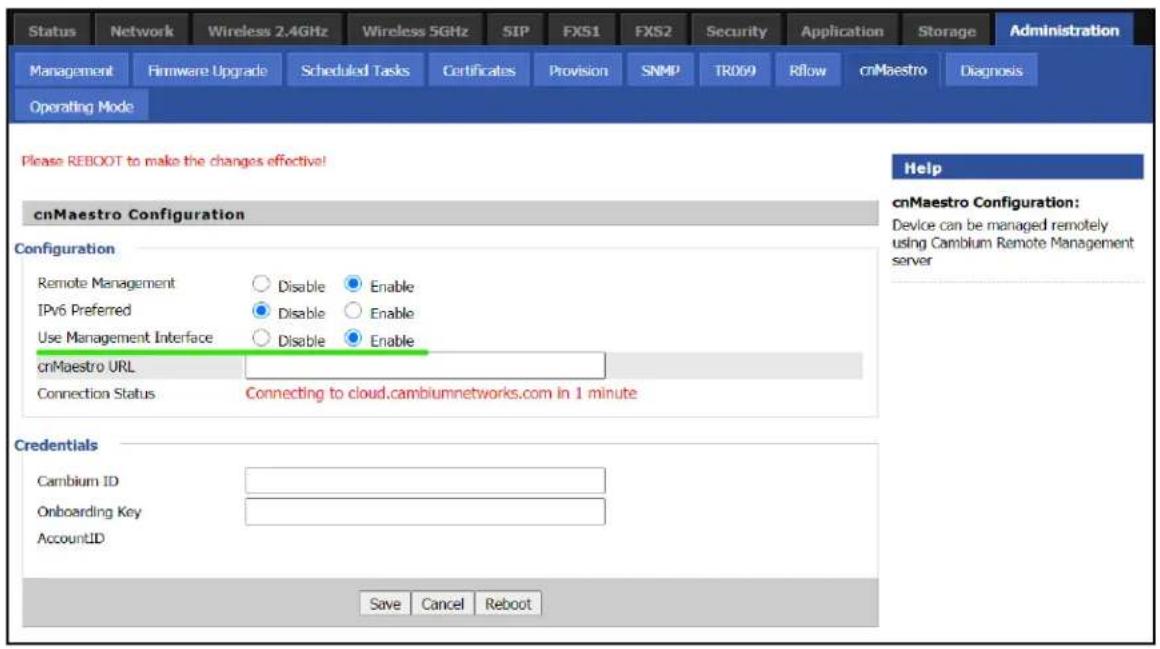
- Use Management Interface - in a multi WAN configuration, this option allows the user to choose the management WAN as the channel for cnMaestro communication.
For more information on Onboarding cnPilot Wi-Fi routers, refer to cnMaestro User Guide.
Performing speed test
The cnPilot Home Routers support speed test service and it can be triggered from cnMaestro On-Premises server.

Note
The port that is used for Wi-Fi performance in cnMaestro On-Premises is 18301 (UDP and TCP).
The cnMaestro On-Premises supports the speed test feature from 1.5.1 release onwards. For more information, refer to Wi-Fi performancén On-Premises User Guide.
Chapter 3: Advanced Configuration
This chapter guides users to execute advanced (full) configuration through admin mode operation.
This chapter contains the following topics:
- Two-Level Management
- Setting the time zone
- Status
- Configuring the Internet connection
- Custom factory default configuration
- Configuring as Range Extender / Wi-Fi Repeater
- Wireless
- SIP
- FXS1
- FXS2
- Security
- Application
- Administration
- System Log
- Logout
- Reboot
Two-Level Management
This section explains password setup procedure for an administrator or user and adjusting the basic and advanced settings.
cnPilot Home Router supports two-level management: administrator and user. For administrator mode operation, type "admin/admin" on Username/Password and click Login to begin configuration. For user mode operation, type "user/user" on Username/Password and click Login to begin configuration.

Note
It is highly recommended to change the admin/user passwords to non-default values.
Setting the time zone
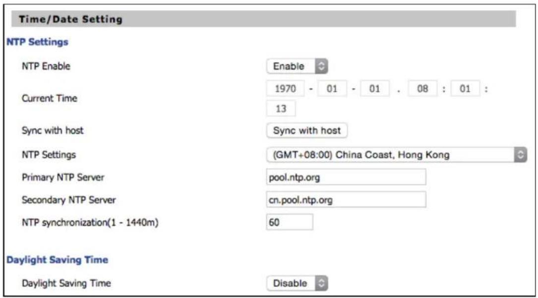
Table 6: Setting time zone
| Field Name Description | |
| NTP Enable Enable | NTP (Network Time Protocol) to automatically retrieve time and date settings for the device. |
| Current Time When | NTP Enable is set to “Disable”, manually configure the time and date via the Current Time parameter. |
| Sync with host | Press button to synchronize the host PC date, time and time zone. |
| Primary NTP Server | Primary and secondary NTP server address for clock synchronization. A valid NTP server must be reachable for full NTP functionality. |
| Secondary NTP Server | |
| NTP Synchronization (1-1440m) | The synchronization period with NTP (1-1440 minutes), default is 60. |
Status

FXS Port Status
FXS Port Status
| FXS 1 Hook State | On |
| FXS 1 Port Status | Idle |
| FXS 2 Hook State | On |
| FXS 2 Port Status | Idle |
Network Status
Active WAN Interface
| Connection Type | DHCP | |
| IP Address | 192.168.210.230 | Renew |
| Link-Local IPv6 Address | ||
| Subnet Mask | 255.255.255.0 | |
| Default Gateway | 192.168.210.254 | |
| Primary DNS | 8.8.8.8 | |
| Secondary DNS | 8.8.4.4 | |
| IPv6 PD Prefix | ||
| IPv6 Domain Name | ||
| IPv6 Primary DNS | ||
| IPv6 Secondary DNS | ||
| WAN Port Status | 1000Mbps Full |
19060 VOICE INTERNET Vian Status
| TR069_VOICE_INTERNET Vlan Status | |
| Connection Type | DHCP |
| MAC Address | 00:04:56:04:27:89 |
| IP Address | 10.110.134.15 |
| Subnet Mask | 255.255.255.0 |
| Default Gateway | 10.110.134.254 |
| Primary DNS | 10.110.12.30 |
| Secondary DNS | 10.110.12.31 |
| VPN Status | |
| VPN Type | Disable |
| Initial Service IP | |
| Virtual IP Address | |
| LAN Port Status | |
| IP Address | 192.168.11.1 |
| Subnet Mask | 255.255.255.0 |
| LAN1 | Link Down |
| LAN2 | Link Down |
| LAN3 | 100Mbps Full |
| LAN4 | Link Down |
Wireless Info
Wireless 2.4GHz
| Radio On/Off | On |
| Network Mode | 11b/g/n |
| Current Channel | 1 |
| Channel Bandwidth | 40MHz |
| BSSID | 00:04:56:04:27:88 |
| Number of Device | 0 |
SSID2
| BSSID | 00:04:56:04:27:89 |
| Number of Device | 0 |
SSID3
| BSSID | 00:04:56:04:27:8A |
| Number of Device | 0 |
SSID4
| BSSID | 00:04:56:04:27:8B |
| Number of Device | 0 |
System Status
System Status
| Current Time | 2016-01-19 05:47:28 |
| Elapsed Time | 1 Min |
| Status | Network | Wireless | SIP | FXS1 | FXS2 | Security | Application | Storage | Administration |
| Basic | LAN Host | Syslog | |||||||
| Refresh | Clear | Save | |||||||
| Manufacturer: CAMBIUM NETWORKS ProductClass: cnPilot R200P SerialNumber: BuildTime: 201711212052 IP: 192.168.11.1 HWVer: V1.3 SWVer: 4.3.4-R5 <Tue Nov 21 07:04:20 2017> DEV_MANAGER[13914]: Not able to find [ device_id ] in keystore <Tue Nov 21 07:04:20 2017> DEV_MANAGER[13914]: Required on-boarding credentials not configured, cann... <Tue Nov 21 07:04:20 2017> DEV_MANAGER[13914]: Unable to discover cnMaestro URL (re-discover in 68 s... <Tue Nov 21 07:04:20 2017> DEV_MANAGER[13914]: Attempting (re)connection in 68 seconds <Tue Nov 21 07:05:29 2017> DEV_MANAGER[13914]: Not able to find [ device_id ] in keystore <Tue Nov 21 07:05:29 2017> DEV_MANAGER[13914]: Required on-boarding credentials not configured, cann... <Tue Nov 21 07:05:29 2017> DEV_MANAGER[13914]: Unable to discover cnMaestro URL (re-discover in 73 s... <Tue Nov 21 07:05:29 2017> DEV_MANAGER[13914]: Attempting (re)connection in 73 seconds <Tue Nov 21 07:06:43 2017> DEV_MANAGER[13914]: Not able to find [ device_id ] in keystore <Tue Nov 21 07:06:43 2017> DEV_MANAGER[13914]: Required on-boarding credentials not configured, cann... <Tue Nov 21 07:06:43 2017> DEV_MANAGER[13914]: Unable to discover cnMaestro URL (re-discover in 65 s... <Tue Nov 21 07:06:43 2017> DEV_MANAGER[13914]: Attempting (re)connection in 65 seconds <Tue Nov 21 07:07:49 2017> DEV_MANAGER[13914]: Not able to find [ device_id ] in keystore <Tue Nov 21 07:07:49 2017> DEV_MANAGER[13914]: Required on-boarding credentials not configured, cann... <Tue Nov 21 07:07:49 2017> DEV_MANAGER[13914]: Unable to discover cnMaestro URL (re-discover in 76 s... <Tue Nov 21 07:07:49 2017> DEV_MANAGER[13914]: Attempting (re)connection in 76 seconds <Tue Nov 21 07:09:06 2017> DEV_MANAGER[13914]: Not able to find [ device_id ] in keystore <Tue Nov 21 07:09:06 2017> DEV_MANAGER[13914]: Required on-boarding credentials not configured, cann... <Tue Nov 21 07:09:06 2017> DEV_MANAGER[13914]: Unable to discover cnMaestro URL (re-discover in 303 ... <Tue Nov 21 07:09:06 2017> DEV_MANAGER[13914]: Attempting (re)connection in 5 minutes <Tue Nov 21 07:14:10 2017> DEV_MANAGER[13914]: Not able to find [ device_id ] in keystore <Tue Nov 21 07:14:10 2017> DEV_MANAGER[13914]: Required on-boarding credentials not configured, cann... <Tue Nov 21 07:14:10 2017> DEV_MANAGER[13914]: Unable to discover cnMaestro URL (re-discover in 341 ... <Tue Nov 21 07:14:10 2017> DEV_MANAGER[13914]: Attempting (re)connection in 5 minutes | |||||||||
Table 7: Status > Basic Page
| Description |
| This webpage shows the status information about the Product, Network, and System including Information, SIP Account Status, FXS Port Status, Network Status and Wireless Info. |
Configuring the Internet connection
In Network > WAN page, WAN connections may be inserted or deleted. For more information on Connection setting refer to Configuring the Internet connection.

Table 8: Configuring the Internet connection
| Field Name Description | |
| Connect Name Use keywords to indicate WAN port service model. | |
| Service Chose the service mode for the created connection. | |
| IP Protocol Version | IPv4 and IPv6 are supported. |
| WAN IP Mode Choose Internet connection mode, DHCP, PPPoE, Static or Bridge. | |
| NAT Enable Enable or disable NAT. | |
| VLAN ID | Note Multiple WAN connections may be created with the same VLAN |
| DNS Mode Select | DNS mode, options are Auto and Manual:When DNS mode is Auto, the device under LAN port will automatic obtain the preferred DNS and alternate DNS.When DNS mode is Manual, the user should manually configure the preferred DNS and alternate DNS. |
| Primary DNS Enter the preferred DNS address. | |
| Secondary DNS Enter the secondary DNS address. | |
| DHCP Displayed when WAN IP Mode is set to DHCP. | |
| DHCP Renew Refresh the DHCP IP. | |
| DHCP Vendor (Option60) | Specify the DHCP Vendor field.Display the vendor and product name. |
Custom factory default configuration
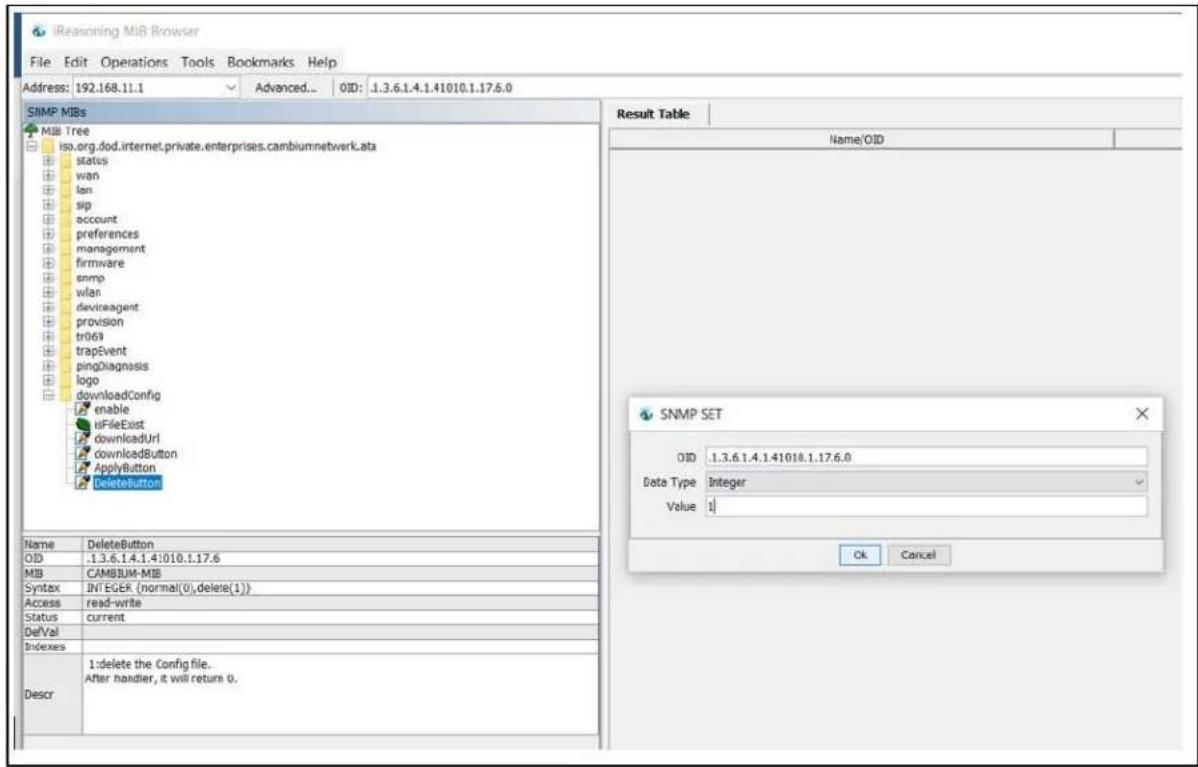
cnPilot Home Router supports custom factory default configuration. This feature is available from release 4.5-R7 onwards. This feature allows user to generate their own customized default configuration file for the device(s). After the installation, this customized default configuration gets applied to the device each time after the device is factory reset. A TFTP server and SNMP browser are required to configure custom factory default. Recommended tool for TFTP server is tftpd64 and for SNMP browser is iReasoning MIB. This setting can be done from either WAN or LAN. To configure factory default from WAN, select Enable from remote SNMP login drop-down as shown in following figure.
![Cambium Networks Firmware Version 4.5-R7 Current Time 2019-05-30 01:36:35 Admin Mode [Logout] [Reboot] Status Network Wireless 2.4GHz Wireless 5GHz SIP FXS1 FXS2 Security Application Storage Administration Management Firmware Upgrade Scheduled Tasks Certificates Provision SNMP TR069 Rflow cnMaestro Diagnosis Operating Mode SNMP Configuration SNMP Configuration SNMP Service Enable ▼ Remote SNMP login Enable ▼ Trap Server Address Read Community Name public Write Community Name private Trap Community trap Trap period interval(sec) 300 Save Cancel Reboot Help SNMP Configuration: Allow the device to be managed by the Manager which is set in the SNMP Manager IP.](/content/2026/05/1044932/images/da2c88aac4ea6ad826975b89b9e28a7fd4bfb5854c4bf339edfe75ba11768932.jpg)
To load the customized default configuration file, perform the following steps:
- Build your customized default configuration file by configuring a router through GUI.
-
Save the configuration and reboot the router.
-
Login to the router and export the configuration.
- Load the exported configuration file and copy to the TFTP server.
This becomes the custom default configuration.
- Download cambium-ata-mib file from Cambium Networks Support Site.
- Open MIB browser and load cambium-ata-mib file.
- On the left pane, expand downloadConfig.

- Double-click enable and typing value to enable custom configuration file as factory default configuration.

- Double-click downloadUrl and provide the tftp custom configuration file laocation in Value.
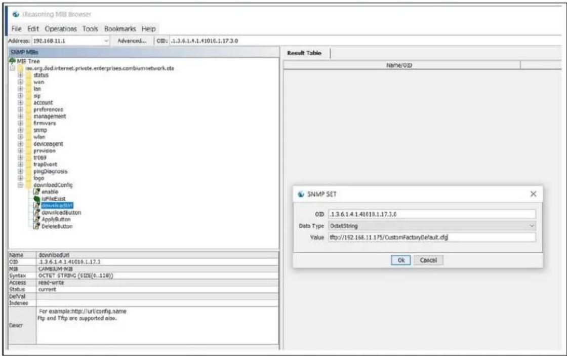
- Double-click downloadButton and typein Value.
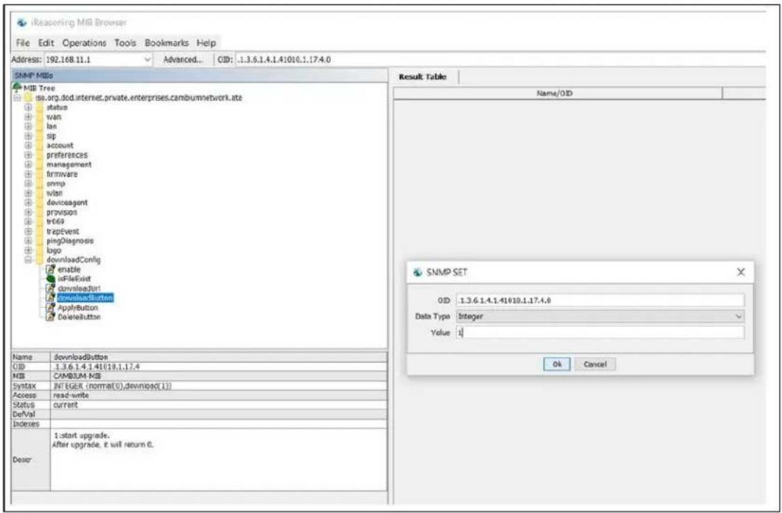
- Double-click on ApplyButton and typing Value.

- Reboot the router.
Router saves this configuration file as default factory settings. After reboot, router starts with this configuration.
To go back to Cambium Networks default factory reset settings, double-click DeleteButton, type Value and reboot the router. After reboot, router starts with Cambium Networks default factory reset settings.
Configuring as Range Extender / Wi-Fi Repeater
cnPilot Home Router devices can be configured as wireless repeater and used as range extender. This feature can be used to extend the wireless networks in a big homes or places where the wireless coverage provided by the Base AP to be extended . This feature is also important for small and medium business establishments with only one internet drop point that can be used to connect only one Access Point and using the Repeater functionality internet coverage that can be extended to other areas.
Repeater configuration
The first AP with wired internet link on WAN port is referred to as the Base AP. The AP that extends the internet link as a wireless extender, with no physical WAN port connection, is referred to as a Repeater AP. The repeater AP connects with base AP over the air. User devices are able to connect to repeater and the base SSIDs.
Base AP configuration for repeater mode
Any cnPilot Home Router AP can act as a base AP and can provide connectivity to another cnPilot Home Router repeater AP. There is no special configuration required on the base AP. Secure PSK based SSID - preferably on 5 GHz and configured with WPA2-PSK that can be used by the extender AP to connect.
Repeater AP configuration
cnPilot Home Router AP can be configured as Repeater AP and they can connect with the base AP as Wi-Fi extender to increase the coverage of existing base AP's.
Repeater AP configuration
To configure Repeater AP, perform the following steps:
- Under Wireless Network, select Repeater from Wireless Connection Mode drop-down.

After configuring Wireless Connection Mode as Repeater, a new Repeater tab is added in the existing tabs under Wireless 2.4GHz or Wireless 5 GHz where the Repeater mode is selected.

- Click on the Repeater tab and check the available SSIDs with their Authentication and Encryption mode. Select SSID of your Base AP and press Connect to initiate the Repeater connection with Base AP.

- After selecting the Base AP SSID in the list of Available SSIDs, click Connect, an option to select Authentication mode, Encryption type and a text box to enter the password for the selected SSID are displayed.
After entering all the information click OK to make the Repeater mode connection with selected SSID.

The Repeater link comes up. Verify the Connection Status as Connected and it also shows the name of SSID where it is connected.

- Click Save to save the configurations and reboot the AP. After rebooting the Repeater AP, check that the Repeater Link is up with the Base AP SSID previously selected automatically.

Repeater AP LAN IP/WAN IP changes
If both Base AP and Repeater AP has same LAN IP/range as 192.168.11.xx, then Repeater AP's LAN IP range automatically changes to 192.168.12.xx and repeaters LAN IP is 192.168.12.1. Repeater AP's WAN Port/internet port gets IP address from the configured LAN DHCP server of the base AP.

Note
If cnPilot Home Router device is configured as a Repeater, it changes from 192.168.11.x pool on the LAN side to 192.168.12.x pool. This sticks around unless we factory reset the Repeater AP. It is recommended not to swap the Base and Repeater AP configurations across devices. And if that is really required, then the user must factory reset the Repeater AP before using it elsewhere.
In the above configuration method, the Repeater is in DHCP/NAT mode, hence the wireless client gets 192.168.12.x IP. Only limitation of this method is, any shared network resources, like printers, Sonos, NAS etc must be connected only to the primary/base AP in order to be accessible from all the clients. Clients/Devices connected to the Repeater AP cannot be accessed from client in the primary/base AP.
To unify all clients under a single subnet, configure the Repeater AP with 2 WAN profiles:
- Wan profile 1 : Service: Internet_Voice WAN IP Mode: Bridge
- Wan profile 2 : Service: Management WAN IP Mode: NAT/DHCP, also enable Use Management Interface under Administration > cnMaestro.
With this configuration all base and repeater's client is in single subnet 192.168.11.x and able to access share resources.


Repeater mode best practices
- If both Base AP and Repeater AP are dual band, then configure the Repeater AP to connect on 5 GHz and provide Client Connectivity or User Wireless Connectivity on 2.4 GHz/5 GHz.
- Place the Repeater AP well within the range of the Base AP for a stable Repeater link.
- The same radio on the Repeater AP, can be used to connect to the Base AP as extender and provide Wireless User Connectivity also. However with reduced bandwidth available for user traffic.
- Creating multi hops of Repeater mode degrades performance, increase latency and it is not recommended.
Network
You can configure the WAN port, LAN port, DDNS, Multi WAN, DMZ, MAC Clone, Port Forward and other parameters in this section of the web management interface.
WAN
This page allows you to set WAN configuration with different modes. Use the Connection Type dropdown menu to choose one WAN mode and then the corresponding page is displayed.

Note
By default, Management access over WAN is disabled for security concerns and can be enabled if required. For more information, refer to Enabling Mangement access for wireless clients.
By default, SNMP access over WAN interface is disabled for security concerns and can be enabled if required. For more information, refer to Enabling SNMP access over WAN.
WAN settings
The following Table 9 shows the WAN settings information.
Table 9: Connect name
| Content Define Description | |||
| Connect Name | 1_MANAGEMENT_VOICE_INTERNET_R_VID | WAN Connection name. | |
| Delete Connect | To delete the selected connection name. | ||
| Service VOICE The connection solely supports VOICE service. | |||
| IP Protocol Version | IPv4 Use protocol version | on lpv4 for WAN Interface. | |
| IPv6 Use protocol version | on lpv6 for WAN Interface. | ||
| WAN IP Mode | STATIC Set the IP address, Subnet Mask and Default Gateaway from ISP provider. | ||
| DHCP Provides IP address, Subnet Mask and Default Gateaway from DHCP server. | |||
| PpoE | Set the PpoE account and PpoE password received from provider. | ||
| Bridge To enable Route | Mode, please turn off 'NAT Enable'. Route Mode must not be used with Multi WAN Configuration. | ||
| MAC Address Clone | Clone third party device MAC Address. | ||
| NAT Enable | Enable Network Address Translation. | ||
| Owerwrite NAT IP | Overwrite NAT IP with given IP. | ||
| VLAN Mode | Enable Enable VLAN Mode. | ||
| Trunk Enable Trunk. | |||
| VLAN ID 1-4 | 094 Specify required VLAN ID. | ||
| DNS Mode | Manual Configure DNS servers manually. | ||
| Auto Configure DNS servers automatically. | |||
| DHCP Renew | Renew your DHCP IP. | ||
| DHCP Vendor (Option 60) | Configure required DHCP Vendor Class name. | ||
| Port Bind L | AN 1-4 Bind 1 or more | LAN ports to the INTERNET WAN profile. | |
| SSID 1-4 Bind 1 or more | SSIDs to the INTERNET WAN profile. | ||
For example:
1_TR069_R_VID_2 (First Interface, Service is TR069, NAT Mode, VLAN ID is 2).
2_INTERNET_B_VID (Second Interface, Service is INTERNET, Bridge Mode, VLAN is disabled).
Overview
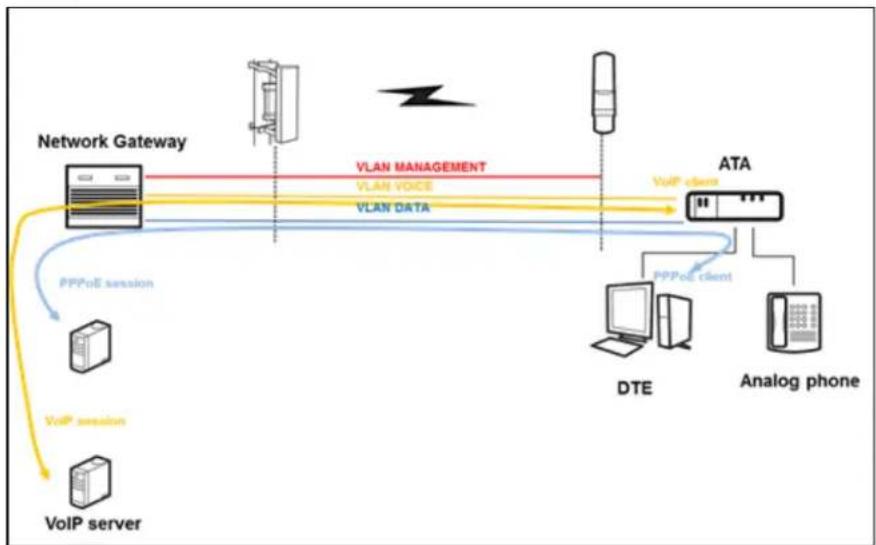
Multi WAN is used to implement the distribution of different kinds of services, and device's Multi WAN supports the distribution of data services, voice services and management services. By setting different VLANs, different kinds of data is distributed to the corresponding networks.
For example, INTERNET and Other VLAN supports data transmission, VOICE VLAN supports voice transmission and TR069 VLAN supports WEB, Telnet and TR069 services transmission.
Figure 6:Multi VLAN

flowchart
graph TD
    A["VLAN1"] --> B["B"]
    C["VLAN2"] --> D["R"]
    E["VLAN3"] --> F["B"]
    G["TR069, VoIP"] --> H["Data Flow"]
    I["Gateway"] --> J["Output"]
    style A fill:#f9f,stroke:#333
    style C fill:#f9f,stroke:#333
    style E fill:#f9f,stroke:#333
    style G fill:#ccf,stroke:#333
    style I fill:#ccf,stroke:#333
There following are the advanced functions available when using multi WAN setting:
- PPPoE Bridge allows PPPoE-only packets to pass, which can prohibit Layer 2 packets from flooding the device LAN ports.
- Hardware Bridge operates as a Layer 2 Switch to increase throughput between WAN and LAN
• VLAN Trunk allows tagged packets to be switched to LAN ports directly.
- IPTV may be supported with other VLAN-configured LAN ports.
- Multiple WAN link (i.e. Connect Name) can be configured with same VLAN ID.
Figure 7: Multi WAN network
flowchart
graph TD
    A["VoIP server"] -->|VoIP session| B["Network Gateway"]
    B -->|VLAN DATA| C["ATA"]
    C -->|VLAN MANAGEMENT| B
    C -->|PPPoE client| D["DTE"]
    C -->|PPPoE session| E["Analog phone"]
    B --> F["VLAN VOICE"]
    B --> G["PPPoE session"]
    style A fill:#f9f,stroke:#333
    style B fill:#ccf,stroke:#333
    style C fill:#cfc,stroke:#333
    style D fill:#fcc,stroke:#333
    style E fill:#cff,stroke:#333
    style F fill:#ffc,stroke:#333
    style G fill:#ffc,stroke:#333
Change in Port Binding behaviour
Starting from the version 4.4 of the Cambium Networks cnPilot Home Router software, the port binding feature is introduced. This change requires, that users creating non-default WAN INTERNET profiles, must explicitly select/bind one or more LAN ports and/or SSIDs, to the created INTERNET WAN profile as per need. Software before 4.4 had an issue, where in such situations all ports/WLANs were automatically bound to such an INTERNET WAN profile created by the users.
Users running 4.3.4 or lower software and upgrading to 4.4 or newer software, MUST ensure that they update their port binding configuration by explicitly selecting one or more LAN ports and/or SSIDs, before upgrading, to avoid problems related to Internet access from LAN/WLAN clients.
Customers using default WAN profile remain unaffected. Also, customers using non-default WAN profile who have explicitly bound their required LAN ports and/or SSIDs to their INTERNET WAN profile experiences no problems after upgrade.
When creating a new INTERNET WAN profile, select one or more LAN ports and/or SSIDs as shown below Figure 8.

Figure 8: Port Binding behaviour
Static IP
This configuration is used when a user receives a fixed public IP address or a public subnet, namely multiple public IP addresses from the Internet providers. A Cable service provider offers a fixed public IP, while a DSL service provider offers a public subnet. If you have a public subnet, you can assign an IP address to the WAN interface.
Table 10: Internet
| Static | |
| IP Address | 192.34.30.69 |
| Subnet Mask | 255.255.255.248 |
| Default Gateway | 192.34.30.65 |
| DNS Mode | Manual ◇ |
| Primary DNS Address | 66.185.0.68 |
| Secondary DNS Address | |
| Name Definition | |
| IP Address The IP address of Internet port. | |
| Subnet Mask The subnet mask of Internet port. | |
| Default Gateway The default gateway of Internet port. | |
| DNS Mode Select DNS mode, options are Auto and Manual. | |
| Primary DNS Address The primary DNS address of Internet port. | |
| Secondary DNS Address The secondary DNS address of Internet port | |
DHCP
The DHCP feature allows the cnPilot Home Router to obtain an IP address automatically from a DHCP server. In this case, it is not necessary to assign an IP address to the client manually.

Figure 9:DHCP
Table 11: DHCP
| Field Name Description | |
| DNS Mode Select DNS mode, options are Auto and Manual. | |
| Primary DNS Address Primary DNS of Internet port. | |
| Secondary DNS Address | Secondary DNS of Internet port. |
| DHCP Renew Refresh the | DHCP IP address. |
| DHCP Vendor (Option60) | Specify the DHCP Vendor field. Display the vendor and product name. |
PPPoE
PPPoE is Point-to-Point Protocol over Ethernet. It relies on two widely accepted standards: PPP and Ethernet. It connects users through an Ethernet to the Internet with a common broadband medium, such as a single DSL line, wireless device or cable modem. All the users over the Ethernet can share a common connection.
PPPoE is used for most of DSL modem users. All local users can share one PPPoE connection for accessing the Internet. Your service provider will provide you information about username, password, and authentication mode.
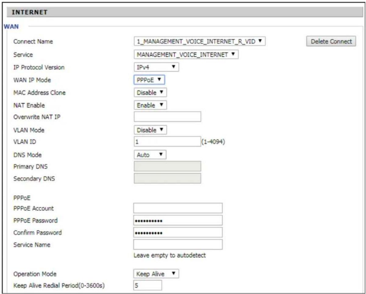
Figure 10: PPPoE
Table 12: PPPoE
| Field Name Description | |
| PPPoE Account Enter a valid username provided by the ISP. | |
| PPPoE Password Enter a valid password provided by the ISP. | |
| Confirm Password Enter your PPPoE password again. | |
| Service Name Enter a service name | me for PPPoE authentication.If it is left empty, the service name is auto detected. |
| Operation Mode Select the mode | of operation, options are Keep Alive, On Demand and Manual:When the mode is Keep Alive, the user sets the 'keep alive' redial period' values range from 0 to 3600s, the default setting is 5 minutes;When the mode is On Demand, the user sets the 'on demand idle time' value in the range of 0-60 minutes, the default setting is 5 minutes;Operation ModeOn Demand Idle Time(0-60m)On DemandOn Demand Idle Time(0-60m)5When the mode is manual, there are no additional settings to configure. |
| Keep Alive Redial Period Set the | interval to send Keep Alive messaging. |
Bridge mode
The Bridge mode under Multi WAN is different with traditional bridge settings. Bridge mode employs no IP addressing and the device operates as a bridge between the WAN port and the LAN port. Route Connection must be built to give IP address to local service on device.
Following is an example of bridge mode:
- TR069_VOICE_INTERNET_R_VID_ is router connection for local service.
- Other_B_VID_ is bridge connection for host of LAN port.

Figure 11:Bridge mode
Table 13: Bridge Mode
| Field Name Description | |
| Bridge Type | |
| IP Bridge Allows | all Ethernet packets to pass. PC can connect to upper network directly. |
| PPPoE Bridge Only | Allow PPPoE packets pass. PC needs PPPoE dial-up software. |
| Hardware IP Bridge | Packets pass through hardware switch with wired speed. Does not support wireless port binding. |
| DHCP Service Type | |
| Pass Through DHCP packets can be forwarded between WAN and LAN, DHCP server in gateway will not allocate IP to clients of LAN port. | |
| DHCP Snooping | When gateway forwards DHCP packets form LAN to WAN it will add option82 to DHCP packet, and it will remove option82 when forwarding DHCP packet from the WAN interface to the LAN interface. Local DHCP service will not allocate IP to clients of LAN port. |
| Local Service Gateway will not forward DHCP packets between LAN and WAN, it also blocks DHCP packets from the WAN port. Clients connected to the LAN port can get IP from DHCP server run in gateway. | |
| VLAN Mode | |
| Disable The WAN interface is untagged. LAN is untagged. | |
| Enable The WAN interface is tagged. LAN is untagged. | |
| Trunk Only valid in bridge mode. All ports, including WAN and LAN, belong to this VLAN Id and all ports are tagged with this VLAN id. Tagged packets can pass through WAN and LAN. | |
VLAN ID Set the VLAN ID. NoteMultiple WAN connections may be created with the same VLAN ID. NoteMultiple WAN connections may be created with the same VLAN ID. | |
| 802.1p Set the priority of VLAN, Options are 0-7. | |
Q-in-Q
Q-in-Q tunneling allows service providers to create a Layer 2 Ethernet connection between two customer sites. Providers can segregate different customers' VLAN traffic on a link (for example, if the customers use overlapping VLAN IDs) or bundle different customer VLANs into a single service VLAN. Data centers can use Q-in-Q tunneling to isolate customer traffic within a single site or to enable customer traffic flows between cloud data centers in different geographic locations. Q-in-Q tunneling adds a service VLAN tag (802.1Q based) before the customer's 802.1Q VLAN tags.
In Q-in-Q tunneling, as a packet travels from a customer VLAN (C-VLAN) to a service provider's or data center VLAN (S-VLAN), another 802.1Q tag for the appropriate S-VLAN is added before the C-VLAN tag.
The C-VLAN tag remains and is transmitted through the network. As the packet leaves the S-VLAN in the downstream direction, the S-VLAN 802.1Q tag is removed.
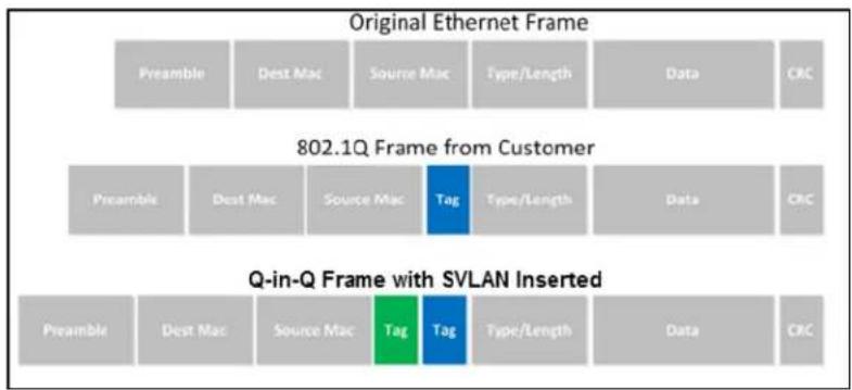
Figure 12:Q-in-Q Frame Format
Table 14: Q-in-Q
![Cambium Networks Current Year 2017-06-29 09:47:43 Admin Node (Código) - [Network] Status Network Wireless 2-KDQ Wireless SCDI SEP TEX3 FX52 Security Application Storage Administration WAN LAN Port Advanced IPv. LAN VPN Port Forward DMF TCP QoS Port Setting Ordering Advance INTERNET WIN Connect Name 1 MANAGEMENT_VVICE_INTERNET_R_VSD Delete Connect Service MANAGEMENT_VICE INTERNET IP Protocol Version SP4 WIN IP Mode DHCP MAC Address Clone Enable NAT Enable Enable Overwrite NAT IP VLAN Mode Enable VLAN ID 10 [1-4094] 802 by 0 SVMAN (Q=0+2) Enable SVMAN ID 2[1-4094] DNS Mode Auto Primary DNS Secondary DNS DHCP DHCP Review Review DHCP Window (Option-64) Cambium-coPilot R201 Port Bind Port_1 Port_3 Port_4 Wireless(SDD) Wireless(SDD1) Wireless(SDD2) wireless(SDD3) Note : WAN connection can not be shared between the binding port, and finally found port WAN connections tied operation will wash away before the other WAN connection to the port. Binding operation! Help WIN IP Nodes Static IP: Set the IP Address, Subnet Mask and Default Gateway that you have gotten from your ISP provider. DHCP: You will get an IP Address,Subnet Mask and Default Gateway from some DHCP Server. AIPC: Set the PRRut Account and PRRut Password that you have gotten from your ISP provider. Note: WAN connection can not be shared between the binding port, and finally found port WAN connections tied operation will wash away before the other WAN connection to the port. Binding operation!](/content/2026/05/1044932/images/aae3a6f733079117077c19203b21210ee37d9d12431df21ab1b509bcfbd78154.jpg)
| Field Name Description |
| VLAN Mode Enable VLAN Mode. |
| SVLAN(Q-in-Q) Enable Q-in-Q feature. |
| SVLAN ID Enter a value for SVLAN ID (1-4094). |

Note
Ensure that Hardware NAT Enable option is disabled in the LAN page for R201/R201P/R201W models. The Hardware NAT Enable option is available only for R201 models. See the following image:

Route mode
The Route mode is an additional mode of operation for the device. In order to setup Route mode operation, turn offNAT Enable. This feature cannot be used with Multi-WAN configuration.


NAT Enable must be disabled for Route Enable to setup.
Chapter 3: Advanced Configuration 52
MAC clone
Some ISPs require to register your MAC address. If you do not wish to re-register your MAC address, you can have the router clone the MAC address that is registered with your ISP. To use the Clone Address button, the computer accessing the web management interface will have the MAC address automatically entered in the Clone WAN MAC field.
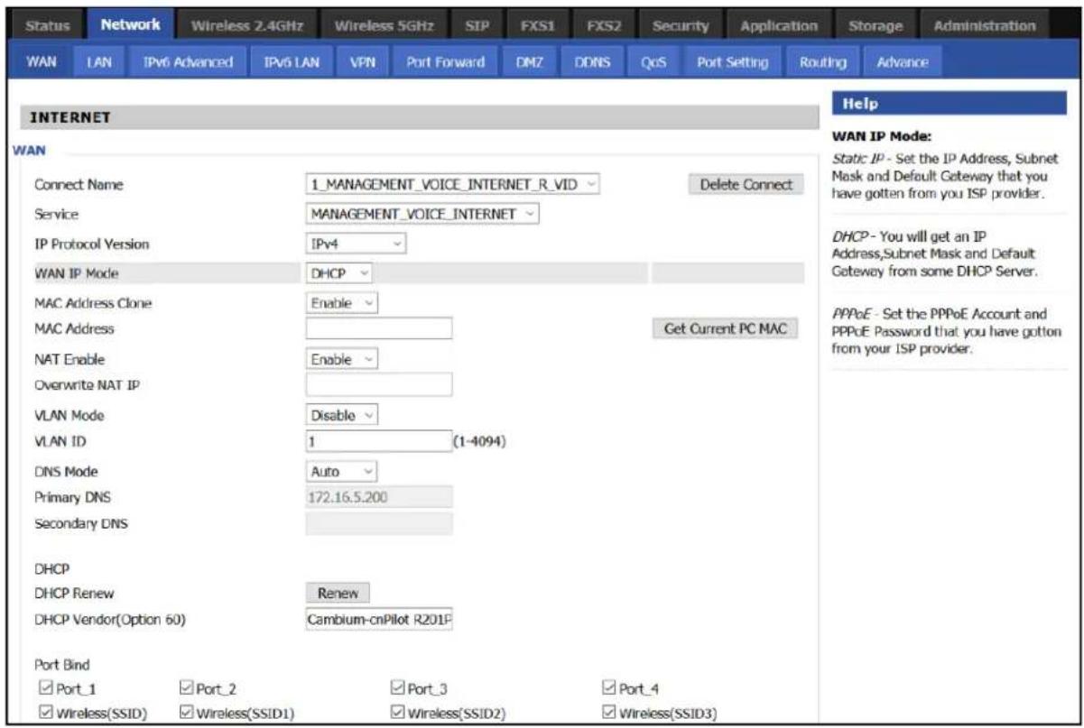
Figure 13:MAC clone
Table 15: MAC clone
| Procedure |
| 1. Press button to get PC's MAC address. |
| 2. Press button to save your changes if users don't want to use MAC clone, pressCancelbutton to cancel the changes. |
| 3. Press button to make the changes effective. |
Fast Bridge setting
To set the Fast Bridge, perform the following steps:
- Login to the web management interface of the cnPilot Home Router. Navigate to Page Administration > Operating Mode. Set Operating mode to Basic Mode. Click Save.

- Open Network > WAN change NAT Enable to Disable. Click Save and then Reboot. The device is now operating in Bridge mode.

- Log into the device and navigate to Status > Basic to display the device configuration.

IPv6 address configuration
The cnPilot Home Router devices support IPv6 addressing, starting from Firmware version 4.3.
This section covers:
• Introduction to lpv6
- Enabling IPv6
- Configuring IPv6
• Viewing WAN port status
• Ipv6 DHCP configuration for LAN/WLAN clients
• LAN DHCPv6
Introduction to lpv6
DHCPv6 protocol is used to automatically provision/configure lpv6 capable end points in a local network. In addition to acquiring an lpv6 IP address for the WAN interface and its associated LAN/WLAN clients, the cnPilot Home Router devices are also capable of prefix delegation.
The cnPilot Home Router devices support the following types of modes of ipv6 addresses:
- Stateless DHCPv6
- Statefull DHCPv6
Table 16: lpv6 Modes
| Mode Description | |
| Stateless In | Stateless DHCPv6 mode, the cnPilot Home Router listen for ICMPv6 Router Advertisements messages which are periodically sent out by the routers on the local link or requested by the node using a Router Advertisements solicitation message. The device derives a unique lpv6 address using prefix receives from the router and its own MAC address. |
| Statefull | In Statefull DHCPv6 mode, the client works exactly as lpv4 DHCP, in which hosts receive both their lpv6 addresses and additional parameters from the DHCP server. |
Enabling IPv6
To enable lpv6 functionality, perform the following steps:
- Navigate to Network > IPv6 Advanced page.
- Select Enable from the IPv6 Enable drop-down list.
- Click Save.
![Cambium Networks Status Network Wireless 2.4GHz Wireless 5GHz SIP FXS1 FXS2 Security Application Storage Administration WAN LAN IPv6 Advanced IPv6 LAN VPN Port Forward DMZ DONS QoS Port Setting Routing Advance IPv6 Advanced Settings IPv6 Enable IPv6 Enable Enable Save Cancel Reboot Firmware Version 4.3-R7 Current Time 2016-10-28 00:21:39 Admin Mode [Logout] [Reboot]](/content/2026/05/1044932/images/d17ef859b0830c31b53c23de05472fbb7ee886f67110b55238586b7b35c18003.jpg)
Figure 14: Enabling IPv6
Configuring IPv6
Configuring Statefull IPv6
Navigate to Network > WAN page. The following window is displayed:
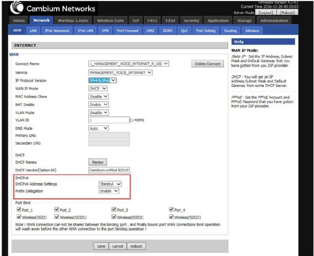
Figure 15:Configuring Statefull IPv6
Table 17: Configuring Statefull lpv6
| Field Name Description | |
| IP Protocol Version Enable IPv4 and IPv6 option. | |
| WAN IP Mode Set it to DHCP. | |
| NAT Enable Select Enable. | |
| DHCPv6 Address Settings | Set it to Statefull mode. |
| Prefix Delegation Select | Enable. |
Configuring Stateless lpv6
To configure Stateless lpv6, see Figure 16

Figure 16:Configuring Stateless lpv6
Table 18: Configuring Stateless lpv6
| Field Name Description | |
| IP Protocol Version Enable | Ipv4 and lpv6 option. |
| WAN IP Mode Set it to DHCP. | |
| NAT Enable Select Enable. | |
| DHCPv6 Address Settings | Set it to Stateless mode. |
| Prefix Delegation Select Enable. | |
Viewing WAN port status
To view the status of WAN port, navigate to the Status page.

Figure 17:The Status page
Ipv6 DHCP configuration for LAN/WLAN clients
Wired and wireless clients connected to cnPilot Home Routers can obtain their lpv6 addresses based on the configuration of LAN side DHCPv6 parameters. The cnPilot Home Routers can be either configured as a DHCPv6 server in which the LAN/WLAN clients get lpv6 addresses from the configured pool.
If DHCP server is disabled on the cnPilot Home Routers, the clients get lpv6 addresses from the external DHCPv6 server configured in the network.
LAN DHCPv6
When IPv6 is enabled, the LAN/WLAN clients of cnPilot Home Routers can be configured to receive IPv6 addresses from locally configured IPv6 pool or from an external DHCPv6 server.
To enable LAN DHCPv6 service, see Figure 18.
![Cambium Networks Firmware Version 4.3-R7 Current Time 2016-10-27 08:21:11 Admin Mode [Logout] [Reboot] Status Network Wireless 2.4GHz Wireless 5GHz SIP FXS1 FXS2 Security Application Storage Administration WAN LAN IPv6 Advanced IPv6 LAN VPN Port Forward DMZ DDNS QoS Port Setting Routing Advance IPv6 LAN Setting Help IPv6 LAN Setting IPv6 Address FD00::1 IPv6 Prefix Length 64 (0-128) DHCPv6 Server DHCPv6 Status Enable DHCPv6 Mode Statefull Domain Name cambiumnetworks.com Server Preference 255 (0-255) Primary DNS Server FD00::2 Secondary DNS Server FD00::3 Lease Time 86400 (0-86400sec) IPv6 Address Pool FD00::100 FD00::200 64 Router Advertisement Router Advertisement Enable Advertise Interval 30 (10-1800sec) RA Managed Flag Enable RA Other Flag Disable Prefix Prefix Lifetime 3600 (0-3600sec) Save Cancel Reboot](/content/2026/05/1044932/images/f1181cd9338412c58ab9983a21984010587c5b3f7bd286c552441ba3c5df398e.jpg)
Figure 18: Enabling LAN DHCPv6 service
The following table describes flag mappings of IPv6 router advertisement:
Table 19: IPv6 router advertisement flag mappings
| Method | DHCPv6 | Routeradvertisement | RAManaged | RAOther | Address(Last 64bits) | Prefix | Gateway | DNS | |
| Static None | NA | NA | NA Manual | Manual Manual | Manual | ||||
| SLAAC 0 | 1 | NA | 0 RA | RA RA | None | ||||
| StatelessDHCPv6 | 1 | 1 0 | 1 | RA | RA | RA | DHCPv6 | ||
| StatefullDHCPv6 | 1 | 1 1 | 1 | or 0 | DHCPv6 | DHCPv6 | RA | DHCPv6 |
NA - The value can be 0 or 1.
LAN
The user can plug computers and other devices that need an Internet connection by using the LAN ports.

Figure 19:LAN port
Table 20: LAN port
| Field Name Description | |
| IP Address Enter the | IP address of the router on the local area network. All the IP addresses of the computers which are in the router's LAN must be in the same network segment with this address, and the default gateway of the computers must be this IP address. (The default is 192.168.11.1). |
| Local Subnet Mask | Enter the subnet mask to determine the size of the network (default is 255.255.255.0/24). |
| Local DHCP Server | Enable/Disable Local DHCP Server. |
| DHCP Start Address | Enter a valid IP address as a starting IP address of the DHCP server, and if the router's LAN IP address is 192.168.11.1, starting IP address can be 192.168.11.2 or greater, but should be less than the ending IP address. |
| DHCP End Address | Enter a valid IP address as an end IP address of the DHCP pool. |
| DNS Mode Select DNS mode, options are Auto and Manual. | |
| Primary DNS Enter | the preferred DNS address. |
| Secondary DNS Enter | the secondary DNS address. |
| Client Lease Time This option defines how long the address will be assigned to the computer within the network. In that period, the server does not assign the IP address to the other computer. | |
| DNS Proxy Enable or disable; If enabled, the device forwards the DNS request of LAN-side network to the WAN side network. | |
| Hardware NAT Enable | Enable or disable Hardware NAT |
DHCP server
The router has a integrated Dynamic Host Configuration Protocol (DHCP) server that assigns private IP address to each local client.
The router, by factory default acts a DHCP server for your network so it automatically dispatches related IP settings to any local user configured as a DHCP client. It is highly recommended that you leave the router enabled as a DHCP server if you do not have a DHCP server for your network.

Figure 20: DHCP server
Table 22 DHCP server settings
| Field Name | Description |
| Local DHCP Server | Enable/Disable DHCP server. |
| DHCP Start Address | Enter a value of the IP address pool for the DHCP server to start with when issuing IP addresses. |
| DHCP End Address | Enter a value of the IP address pool for the DHCP server to end with when issuing IP addresses. |
| DNS Mode | If DNS information is to be received from a network server, set this parameter to Auto. If DNS information is to be configured manually, set this parameter to Manual. |
| Primary DNS | 192.168.11.1 |
| Secondary DNS | 8.8.8.8 |
| Client Lease Time(0-86400s) | 86400 |
| DHCP Client List |
Table 21: DHCP server, DNS and Client Lease Time
| Field Name | Description |
| Primary DNS | Specify the Primary DNS address provided by your ISP. If your ISP does not provide it, the router will automatically apply default DNS Server IP address: 202.96.134.33 to this field. |
| Secondary DNS | Specify the Secondary DNS address provided by your ISP. If your ISP does not provide this address, the router will automatically apply default Secondary DNS Server IP of 202.96.128.86 to this field.If both the Primary IP and Secondary IP Address fields are left empty, the router will assign its own IP address to local users as a DNS proxy server and maintain a DNS cache. |
| Client Lease Time | It allows you to set the leased time for the specified PC. |
VPN
cnPilot Home Router supports VPN connections with PPTP-based VPN servers.
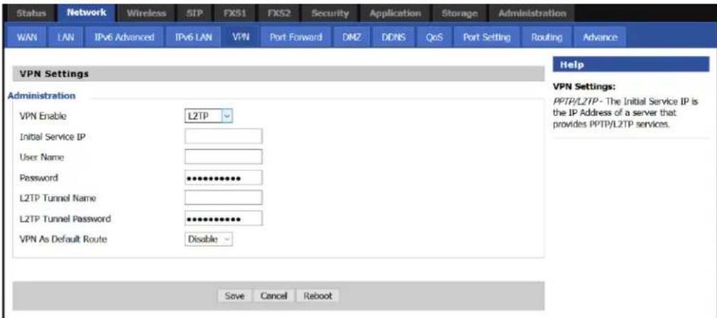
Figure 21:The VPN settings page
Table 22: VPN
| Field Name Description | |
| VPN Enable Enable/ | Disable VPN. If the VPN is enabled, user can select PPTP and L2TP mode VPN. |
| Initial Service IP Enter | VPN server IP address. |
| Username Enter authentication username. | |
| Password Enter authentication password. | |
| L2TP Tunnel Name Enter the name for L2TP tunnel. | |
| L2TP Tunnel Password | Enter the password for L2TP tunnel. |
| VPN As Default Route | Enable/Disable the VPN as default route. |
DMZ

Figure 22:The DMZ page
Table 23: DMZ
| Field Name Description | |
| DMZ Enable Enable/Disable DMZ | |
| DMZ Host IP Address Enter the | private IP address of the DMZ host. |
Port Forward
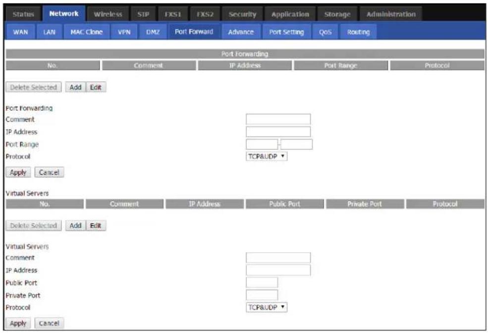
Figure 23:The Port Forward page
Table 24: Elements in the Port Forward page
| Field Name Description | |
| Comment Sets the name of a port mapping rule or comment. | |
| IP Address The IP address of devices under the LAN port. | |
| Port Range Set the port range for the devices under the LAN port (1-65535). | |
| Protocol You can select TCP, UDP, TCP & UDP three cases. | |
| Apply/Cancel After finish configurations, click apply, the number will be generated under NO. List; click Cancel to if you do not want to make the changes. | |
| Comment To set up a virtual server notes. | |
| IP Address Virtual server IP address. | |
| Public Port Public port of virtual server . | |
| Private Port Private port of virtual server. | |
| Protocol You can select from TCP, UDP, and TCP&UDP. | |
| Apply/Cancel After finish configurations, click Apply, the number is generated under NO. Click Cancel to if you do not want to make the changes. | |
DDNS Setting

Figure 24:DDNS Setting
Table 25: Elements in the DDNS Setting page
| Field Name Description | |
| Dynamic DNS Provider | DDNS is enabled and select a DDNS service pro |
| Account Enter the DDNS service account. | |
| Password Enter the DDNS service account password. | |
| DDNS Enter the DDNS domain name or IP address. | |
| Status Displays the DDNS upgrade status. | |
Advance

Figure 25:The Advance page
Table 26: Elements in the advance page
| Field Name Description | |
| Most Nat connections The largest value | which the cnPilot Home Router can provide. |
| Mss Mode Choose Mss Mode as Manual | or Auto. |
| Mss Value Set the value of TCP. | |
| AntiDos-p You can choose to enable or | disable. |
| IP conflict detection You can choose to | enable or disable. |
| IP conflict Detecting Interval Detect IP | address conflicts of the time interval. |
Port Setting

Figure 26:The Port Setting page
Table 27: Port setting
| Field Name Description | |
| WAN Port speed Nego Auto-negotiation, options are Auto, 100M full, 100M half-duplex, 10M half and full. | |
| LAN1-LAN4 Port Speed Nego Auto-negotiation, options are Auto, 100M full, 100M half, 10M half and 10M full. | |
QoS setting
QoS is capability of a network to provide a better service to certain network traffic flows. The primary goal of QoS is to provide a priority including dedicated bandwidth, low latency, and improved loss
characteristics. Ensure that providing priority for one or more flows does not make other flows fail. cnPilot Home Routers are implemented with Token Bucket flow for QoS. If QoS is enabled without adding any rules, then Hardware NAT gets disabled and leads to decreased throughput.
The user can classify traffic based on source, destination IP, and MAC addresses. After classification of traffic, user can assign priority and rate limit the traffic stream. The bandwidth is shared with other low priority queues/traffic if there is no or less traffic than assigned rate limit.
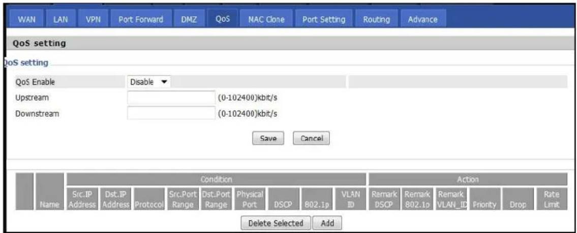
Figure 27:The QoS setting page
Table 28: Elements in the QoS setting page
| Field Name Description | |
| QoS Enable Enable/Disable QoS function. | |
| Upstream Set the upstream bandwidth. | |
| Downstream Set the downstream bandwidth. | |
| Delete Selected Check the items you want to delete, click Delete option. | |
| Add Click Add to add a new rule. | |

Note
From system release 4.2 or later, the QoS bandwidth can be configured for Upstream and Downstream.
Routing

Figure 28: The Static Routing Settings page
Table 29: Elements in the Static Routing Settings page
| Field Name Description | |
| Destination Address of the destination. | |
| Host/Net Indicates whether single host or a network is being specified. If Net, then one more option appears then configure the subnet. | |
| Gateway Gateway IP address | |
| Interface Select the desired LAN/WAN interface. | |
| Comment Comments. | |
Wireless

Note
Starting from 4.4 release, any changes in the Wireless/Radio configuration performed on the cnPilot Home Routers can be applied on the fly and does not require a reboot. However, for all other configuration sections a reboot is required to make new configuration changes effective.
Basic
Table 30: Basic
| Field Name Description | |
| Radio on/off Select Radio | off to disable wireless.Select Radio on to enable wireless. |
| Wireless connection mode | According to the wireless client type, select one of the modes. Modes are AP/ Repeater. Default is AP. |
| Network Mode Choose one | network mode from the drop-down list. For 5 GHz radio the default is 11vht AC/AN/A. Default is 11b/g/n mixed mode. |
| SSID It is the basic identity | of wireless LAN. SSID can be any alphanumeric or a combination of special characters. It will appear in the wireless network access list. |
| Multiple SSID1-SSID3 cnPilot | r190V/r190W/r200/r200P Routers support 4 SSIDs on each radio. |
| Hidden After the item is checked, the SSID is no longer displayed in the search for the Wi-Fi wireless network connection list | |
| Broadcast (SSID) After initial State opening, the device broadcasts the SSID of the router to wireless network. | |
| AP Isolation If AP isolation | is enabled, the clients connected to the AP cannot access each other. It is controlled from 2.4 GHz radio page only. This setting enables / disables the isolation for both 2.4 GHz and 5 GHz radios. |
| MBSSID Isolation If MBSSID | isolation is enabled, the clients connected to different SSIDs on same AP cannot access each other. It is controlled from 2.4 GHz radio page. This setting Enable / Disable the isolation for both 2.4 GHz and 5 GHz radios. |
| BSSID MAC address of the | AP. |
| Frequency (Channel) You can select Auto Select. | |
| HT Physical Mode Operating Mode | . Mixed Mode: In this mode, the previous wireless card can recognize and connect to the Pre-N AP, but the throughput will be affected 2. Green Field: high throughput can be achieved, but it will affect backward compatibility, and security of the system |
| Channel Bandwidth Select | channel bandwidth, default is 20 MHz and 20/40 MHz. Default is 20/40 |
| Guard Interval Select long/short. default is short. | |
| Reverse Direction Grant (RDG) | Enabled: Devices on the WLAN are able to transmit to each other without requiring an additional contention-based request to transfer (i.e. devices are able to transmit to another device on the network during TXOP).Disabled: Devices on the WLAN must make a request for transmit when communicating with another device on the network |
| STBC Space-time Block Code | Enabled: Multiple copies of signals are transmitted to increase the chance of successful deliveryDisabled: STBC is not employed for signal transmission |
| Aggregation MSDU (A-MSDU) | Enabled: Allows the device to aggregate multiple Ethernet frames single 802.1In, thereby improving the ratio of frame data to frame overheadDisabled: No frame aggregation is employed at the router |
| Auto Block Ack Enabled: | Multiple frames are acknowledged together using a single Block Acknowledgement frame.Disabled: Auto block acknowledgement is not used by the device this configuration when low throughput/connectivity issues are experienced by mobile devices |
| Decline BA Request Enabled | Disallow block acknowledgement requests from devicesDisabled: Allow block acknowledgement requests from devices |
| HT Disallow TKIP Enabled: | Disallow the use of Temporal Key Integrity Protocol for connected devicesDisabled: Allow the use of Temporal Key Integrity Protocol for connected devices |
| HT LDPC Enabled: Enable | Low-Density Parity Check mechanism for increasing chance of successful delivery in challenging wireless environmentsDisabled: Disable Low-Density Parity Check mechanism |
Wireless security

Table 31: Wireless security
| Field Name | Description |
| SSID Choice | Select the SSID for which security parameters need to be configured. |
| Security Mode | Select an appropriate encryption mode to improve the security and privacy of your wireless data packets.Each encryption mode will bring out different web page and ask you to offer additional configuration. |
User can configure the corresponding parameters. Here are some common encryption methods:
OPENWEP: A handshake way of WEP encryption, encryption via the WEP key:
Table 32: Wi-Fi Security Setting
| Field Name Description | |
| Security mode This is used to select one of the 4 WEP keys, key settings on the clients show be the same with this when connecting. | |
| WEP Keys Set the WEP key. A-64 key need 10 Hex characters or 5 ASCII characters; choose A-128 key need 26 Hex characters or 13 ASCII characters. | |
| WEP represents Wired Equivalent Privacy, which is a basic encryption method. | |
WPA-PSK, the router will use WPA way which is based on the shared key-based mode:

Table 33: WPA-PSK
| Field Name Description | |
| WPA Algorithms | This item is used to select the encryption of wireless home gateway algorithms, options are TKIP, AES and TKIPAES. |
| Pass Phrase Setting up WPA-PSK security password. | |
| Key Renewal Interval | Set the key scheduled update cycle, default is 3600s. |
WPAPSKWPA2PSK manner is consistent with WPA2PSK settings:
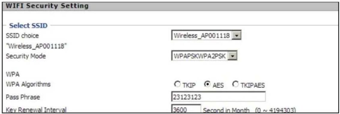
Table 34: WPAPSKWPA2PSK
| Field Name Description | |
| WPA Algorithms The home gateway is | used to select the wireless security encryption algorithm options are TKIP, AES, TKIP / AES mode does not support TKIP algorithms. |
| Pass Phrase Set WPA-PSK/WPA2-PSK | security code |
| Key Renewal Interval Set the key scheduled update cycle, default is 3600s | |
| WPA-PSK/WPA2-PSK WPA/WPA2 security type is a simplified version, which is based on the shared key mode, higher security setting is also relatively simple, suitable for ordinary home users and small businesses. | |
Wireless access policy

Table 35: Wireless Access Policy
| Field Name Description | |
| Access policy Wireless access control | is used to allow or prohibit the specified client to access to your wireless network based on the MAC address. |
| Policy Disable: Prohibition: wireless access control policy.Allow: only allow the clients in the list to access.Rejected: block the clients in the list to access. | |
| Add a station MAC Enter the MAC address of the clients which you want to allow or prohibit. | |
| Example: Prohibit the device whose wireless network card MAC address is 00:1F: D0: 62: BA: FF's to access the wireless network and allow other computers to access the network.Implementation: As shown, the Policy is Reject, add 00:1F: D0: 62: BA: FF to the MAC, click reboot the device settings to take effect. | |
WMM

Table 36: WMM
| Description |
| WMM (Wi-Fi Multi-Media) is the QoS certificate of Wi-Fi Alliance (WFA). This provides you to configure the parameters of wireless multimedia; WMM allows wireless communication to define a priority according to the home gateway type. To make WMM effective, the wireless clients must also support WMM. |
WDS
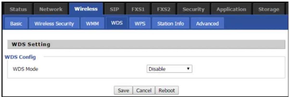
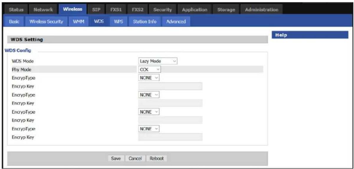
Table 37: WDS
| Description |
| WDS stands for Wireless Distribution System, enabling WDS access points to be interconnected to expand a wireless network. |
WPS
WPS (Wi-Fi Protected Setup) provides easy procedure to make network connection between wireless station and wireless access point with the encryption of WPA and WPA2.

Note
WPS is disabled by default. To enable WPS, under WPS Setting, select Enable from the drop-down and click Apply.
It is the simplest way to build connection between wireless network clients and wireless access point. Users do not need to select any encryption mode and type any long encryption passphrase to setup a wireless client every time. The only requirement is for the user to press the WPS button on the wireless client, and WPS will connect for client and router automatically.
Perform the below steps on cnPilot for WPS (it is applicable only for cnPilot r195W Home Router):
- Tap WPS button on the phone.
-
Press WPS button on cnPilot r195W Home Router (press-and-release).
-
if you press WPS button only once (press and release), then the client connects to 2.4G radio
- if you press WPS button twice within 2 seconds, then the client connects to 5GHz
- if you press and hold WPS button for more than 2 seconds, then no action happens.

Table 38: WPS
| Field Name Description | |
| WPS Setting Enable/Disable | WPS function |
| WPS Summary Display the current status of WPS, including current state, SSSID name, authentication methods, encryption type and the PIN code of this | |
| Generate Generate a new P N code | |
| Reset OOB | · cnPilot Wi-Fi r190V/r190W/r200/r200P Routers use a default security policy to allow other non-WPS users to access and apply. |
| WPS Mode | · PIN: Enter the PIN code of the wireless device which accesses to this LAN in the following option, and press apply. Then cnPilot Home Router r190V/r190W/r200/r200P begins to send signals, turn on the PIN accessing method on the clients, and then it can access the wireless AP automatically.· PBC: There are two ways to start PBC mode, user can press the PBC button directly on the device or select PBC mode on the software and apply. Users can activate WPS connection in WPS mode through these two methods, only when the clients choose PBC access, the clients can connect the AP automatically. |
| WPS Status WPS shows status in three ways:·WSC: Idle·WSC: Start WSC process (begin to send messages)·WSC: Success; this means clients have accessed the AP successfully | |
Station Info
| Status | Network | Wireless | SIP | FXS1 | FXS2 | Security | Application | Storage | Adm | |
| Basic | Wireless Security | WMM | WDS | WPS | Station Info | Advanced | ||||
| Wireless Status | ||||||||||
| Wireless Status | ||||||||||
| Current Channel | Channel 1 | |||||||||
| CAMBIUM_2.4GHz_027898 | 00:04:56:02:78:98 | |||||||||
| Wireless Network | ||||||||||
| Wireless Network | ||||||||||
| MAC Address | Aid | PSM | MimoPS | MCS | BW | SGI | STBC | |||
| 20:54:76:96:9B:1A | 1 | 0 | 3 | 7 | 20M | 0 | 1 | |||
Table 39: Station info
| Description |
| This page displays information about the current registered clients’ connections including operating MAC address and operating statistics. |
Advanced
Table 40: Advanced
| Field Name Description | |
| BG Protection Mode | Select G protection mode, options are on, off and automatic. |
| Beacon Interval | The interval of sending a wireless beacon frame, within this range, it will send a beacon frame for the information of the surrounding radio network. |
| Data Beacon Rate (DTIM) | Specify the interval of transmitting the indication message, it is a kind of cut down operation, and it is used for informing the next client which is going to receive broadcast multi-cast. |
| Fragment Threshold | Specify the fragment threshold for the packet, when the length of the packet exceeds this value, the packet is divided. |
| RTS Threshold | Specify the packet RTS threshold, when the packet exceeds this value, the router will send RTS to the destination site consultation |
| Short Preamble | Default is Enable, cnPilot r190V/r190W/r200/r200P Routers system is not compatible with traditional IEEE802.11, the operation rate can be 1.2Mpbs. |
| Short Slot Enable/Disable short slot. By default, it is enabled. It is helpful in improving the transmission rate of wireless communication. | |
| Tx Burst One | of the features of MAC layer, it is used to improve the fairness for transmitting TCP. |
| Pkt_Aggregate | It is a mechanism that is used to enhance the LAN, in order to ensure that the home gateway packets are sent to the destination correctly. |
| IEEE802.11H support | Enable/Disable IEEE802.11H Support. By default, it is disabled. |
| Country Code | Select country code, options are CN, US, JP, FR, TW, IE, HK and NONE. |
| Wi-Fi Multimedia (WMM) | |
| WMM Capable | Enable/Disable WMM. |
| APSD Capable | Enable/Disable APSD. Once it is enabled, it may affect wireless performance, but can play a role in energy-saving power. |
| WMM Parameters | Press , the webpage will jump to the configuration page of Wi-Fi multimedia. |
| Multicast-to-Unicast Converter | Enable/Disable Multicast-to-Unicast. By default, it is Disabled. |
WDS
See WDS.
WPS
See WPS.
Station Info
See Station Info.
Advanced
See Advanced.
Parental control
Bark
cnPilot Home Routers supports Bark Parental Control application. This manages the bark cloud account and on accessing this link from any LAN client of Access Point (AP) and it identifies all the devices connected to the network. Pairing code is used to identify the AP in the bark cloud account and this code is changed only after factory reset of cnPilot Home Router. The devices are identified based on the MAC address. If any device uses randomized MAC address on every connection, then this device is treated as a guest and guest rules are applied. The device access can be denied completely.
Unlimited clients and unlimited devices can be paired in single account. Bark application can be installed on the child's phone to monitor the device. Child application should be added into the bark cloud settings to monitor the messages or content being consumed by the child. If the bark application is disabled/uninstalled, then a warning message is displayed to the child. The child can remove the application from the phone where a notification is sent to the parent through SMS, E-mail, and, App notification. All settings can be controlled, modified, and updated from bark cloud. Bark cloud allows the device to monitor the traffic and content based on the severity of the settings.
If VPN is enabled on the device, then the traffic is considered as unidentified traffic and all the traffic are discarded. Bark cloud deletes any explicit content of child from apps/sites that are monitored and stores it on a designated private space, and notifies the parent about this activity with a link for the deleted content. To go to bark settings, navigate to Security >Bark. The Bark Settings window is shown in Figure 29.
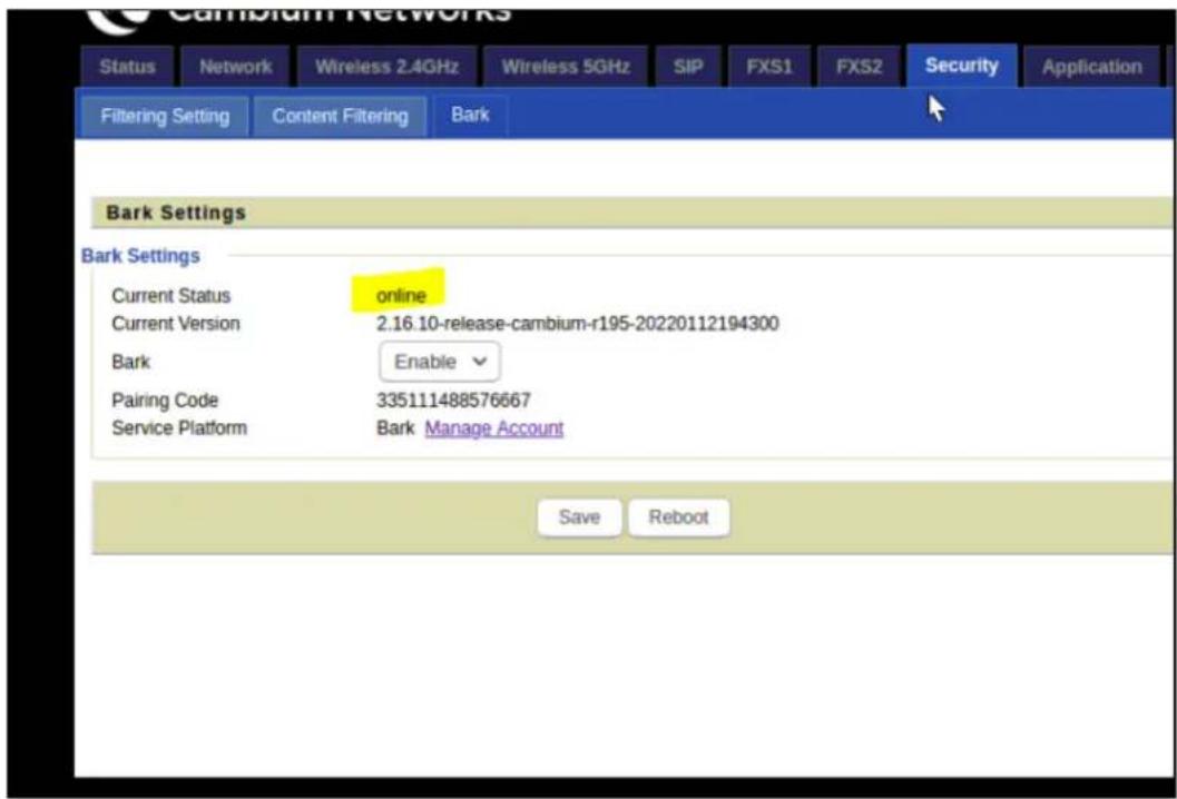
Figure 29:Bark Settings window
Table 41 describes the elements in Bark Settings window.
Table 41: Bark Settings window elements
| Element Description | |
| Current Status Current status of the device. The following are three status of the device:Connecting: Trying to register with the cloud.Ready: Ready to connect to the bark cloud.Online: Successfully registered on the bark cloud. | |
| Current version Displays the current version of the installed software. | |
| Bark To enable / disable the bark settings. | |
| Pairing code Codeto identify the AP. | |
| Service Platform Manages the bark account. | |

Note
Bark has the precedence over parental control. If parental control to be enabled, then disable the bark.
SIP
cnPilot Home Routers have 2 FXS ports to make SIP (Session Initiation Protocol) calls for the supported models. Before registering, the device user should have a SIP account configured by the system administrator or provider. See the section below for more information.
SIP Settings
Table 42: SIP settings
| Field Name Description | |
| SIP T1 The minimum scale of retransmission time | |
| Max Forward SIP | contains Max Forward message header fields used to limit the requests for forwards. |
| SIP Reg User Agent Name | The agent name of SIP registered user |
| Max Auth The maximum number of retransmissions | |
| Mark All AVT Packets | Voice packet marking to enable this item will see the mark on the voice message when the call environment changed (such as press a key during the call) |
| RFC 2543 Call Hold | Enable the Connection Information field displays the address is 0.0.0.0 in the invite message of Hold. Disable the Connection Information field displays the device IP address in the invite message of Hold. |
| SRTP Whether to | enable the call packet encryption function |
| SRTP Prefer Encryption | The preferred encryption type of calling packet (the Message body of INVITE Message) |
| Service Type Choose the service type. | |
| NAT Traversal Enable/Disable NAT TraversalcnPilot Home Router supports STUN Traversal; if user wants to traverse NAT/Firewall, select the STUN. | |
| STUN Server Address | Add the correct STUN service provider IP address. |
| NAT Refresh Interval | Set NAT Refresh Interval, default is 60s. |
| STUN Server Port | Set STUN Server Port, default is 5060. |
Parameters and Settings
Table 43: Parameters and settings
| Field Name Description | |
| Dial Plan Enable/Disable dial plan. | |
| Line Set the line. | |
| Digit Map Enter the | sequence used to match input numberThe syntactic - refer the following Dial Plan Syntactic |
| Action Choose the | dial plan mode from Deny and Dial Out.Deny means cnPilot Home Routers will reject the matched number, while Dial Out means cnPilot Home Routers will dial out the matched number. |
| Move Up Move the | dial plan up the list |
| Move Down Move the | dial plan down the list |
Adding one Dial Plan
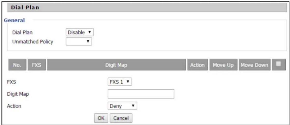
- Enable Dial Plan.
- Click Add, and the configuration table.
- Fill in the value of parameters.
- Press OK to end configuration.
Dial Plan Syntactic
Table 44: Dial Plan
| No. String Description | |
| 1 0 1 2 | 3 4 5 6 7 8 9 * # Allowed characters |
| 2 x Lowercase letter x stands | for one legal character |
| 3 [sequence] | To match one-character form sequence.For example:[0-9]: match one digit from 0 to 9 |
| No. String Description | ||
| [23-5*]: match one character from 2 or 3 or 4 or 5 or * | ||
| 4 | x. | Match to x0 , x1 , x2 .... x3 xn For example:“01.”:can match “0”, “01”, “011”, “0111”, ......, “01111...” |
| 5Replace dialed with substituted.For example:<8:1650>123456: input is “85551212”, output is“16505551212” | ||
| 6 x,y | Make outside dial tone after dialing “x”, stop until dialing character “y”For example:“9,1xxxxxxxxxxx”: the device reports dial tone after inputting “9”, stops tone until inputting “1”“9,8,010x”: make outside dial tone after inputting “9”, stop tone until inputting “0” | |
| 7 | T | Set the delayed time.For example:“<9:111>T2”: The device will dial out the matched number “111” after 2 seconds. |
Blacklist
In this page, user can upload or download blacklist file, and can add or delete or edit blacklist one by one.


- Click to select the blacklist file and click to upload it to cnPilot Home Router. Click to save the blacklist file to your local computer.
- Select one contact and click edit to change the information, click Delete to delete the contact, click Move to phonebook to move the contact to phonebook.
- Click Add to add one blacklist, enter the name and phone number, click OK to confirm and click Cancel to cancel.

Call Log
To view the call log information such as redial list (incoming call), answered call and missed call.
Table 45: Call log
| Index | NUMBER | Start Time | Duration | |
| 1 | 123 | 10/28 10:30 | 00:00:07 | |
| 2 | 010123 | 10/28 12:02 | 00:00:01 | |
| 3 | 010123 | 10/28 16:16 | 00:00:00 | |
| 4 | 010123 | 10/28 16:16 | 00:00:00 | |
| 5 | 123 | 10/28 16:20 | 00:00:13 | |
| 6 | 123 | 10/28 16:21 | 00:00:34 | |
| 7 | 123 | 10/29 10:50 | 00:00:10 | |
| 8 | 123 | 10/29 14:36 | 00:00:01 | |
| 9 | 123 | 10/29 15:05 | 00:00:23 | |
| 10 | 123 | 10/29 15:06 | 00:00:05 |
Redial List
| Answered Calls | ||||
| Index | NUMBER | Start Time | Duration | |
| 1 | 22222 | 10/21 09:56 | 00:00:40 | |
| 2 | 110 | 10/21 18:14 | 00:00:03 | |
| 3 | 110 | 10/21 18:15 | 00:00:07 | |
| 4 | sipp | 10/23 13:40 | 00:00:06 | |
| 5 | sipp | 10/24 18:05 | 00:00:05 | |
| 6 | sipp | 10/24 18:05 | 00:00:05 | |
| 7 | sipp | 10/25 15:38 | 00:00:03 | |
| 8 | sipp | 10/25 15:42 | 00:00:06 | |
| 9 | sipp | 10/25 15:55 | 00:00:10 | |
| 10 | sipp | 10/25 16:03 | 00:00:02 | |
Answered Calls

VoIP QoS

Table 46: VoIP QoS
| Field Name Description |
| SIP /RTP QoS The default value is 0, you can set a range of values is 0-63 |
FXS1
SIP Account
Basic
Set the basic information provided by your VOIP Service Provider, such as Phone Number, Account, password, SIP Proxy and others.

Warning
3-wire connection is not supported.

Table 47: SIP Account - Basic
| Field Name Description | |
| Line Enable Enable | /Disable the line. |
| Peer To Peer | Enable/Disable PEER to PEER.If enabled, SIP-1 will not send register request to SIP server; but in Status/Account Status webpage, Status is Registered; lines 1 can dial out, but the external line number cannot dial line1. |
| Proxy Server The | P address or the domain of SIP Server |
| Outbound Server | The IP address or the domain of Outbound Server |
| Backup Outbound Server | The IP address or the domain of Backup Outbound Server |
| Proxy port SIP Service port, default is 5060 | |
| Outbound Port Outbound Proxy's Service port, default is 5060 | |
| Backup Outbound Port | Backup Outbound Proxy's Service port, default is 5060 |
| Display Name The | number will be displayed on LCD |
| Phone Number Enter telephone number provided by SIP Proxy | |
| Account Enter SIP | account provided by SIP Proxy |
| Password Enter SIP | password provided by SIP Proxy |
Audio Configuration
Table 48: Audio configuration
| Audio Configuration | |||
| Codec Setup | |||
| Audio Codec Type 1 | G.723▼ | Audio Codec Type 2 | G.711U▼ |
| Audio Codec Type 3 | G.711A | Audio Codec Type 4 | G.722▼ |
| Audio Codec Type 5 | G.711U | Audio Codec Type 6 | OPUS▼ |
| G.722 | |||
| G.729 | |||
| G.723 Coding Speed | G.723 | Packet Cycle(ms) | 20▼ |
| Silence Supp | OPUS | Echo Cancel | Enable▼ |
| Auto Gain Control | Disable▼ | Use First Matching Vocoder in 200OK SDP | Disable▼ |
| Codec Priority | Remote▼ | Packet Cycle Follows Remote SDP | Disable▼ |
| FAX Configuration | |||
| FAX Mode | T.38▼ | ByPass Attribute Value | fax/modem▼ |
| T.38 CNG Detect Enable | Disable▼ | T.38 CED Detect Enable | Enable▼ |
| gpmd attribute Enable | Disable▼ | T.38 Redundancy | Disable▼ |
| Max Fax Rate | 14400▼ | ||
| Supplementary Service Subscription | |||
| Supplementary Services | |||
| Call Waiting | Enable▼ | Hot Line | |
| MWI Enable | Enable▼ | Voice Mailbox Numbers | |
| MWI Subscribe Enable | Disable▼ | VMWI Serv | Enable▼ |
| DND | Disable▼ | ||
| Speed Dial | |||
| Speed Dial 2 | Speed Dial 3 | ||
| Field Name Description | |
| Audio Codec Type1 Choose | the audio codec type from G.711U, G.711A, G.722, G.729, G.723, OPUS |
| Audio Codec Type2 Choose | the audio codec type from G.711U, G.711A, G.722, G.729, G.723, OPUS |
| Audio Codec Type3 Choose | the audio codec type from G.711U, G.711A, G.722, G.729, G.723, OPUS |
| Audio Codec Type4 Choose | the audio codec type from G.711U, G.711A, G.722, G.729, G.723, OPUS |
| Audio Codec Type5 Choose | the audio codec type from G.711U, G.711A, G.722, G.729, G.723, OPUS |
| G.723 Coding Speed Choose | the speed of G.723 from 5.3kbps and 6.3kbps |
| Packet Cycle The RTP packet | cycle time, default is 20ms |
| Silence Support Enable/Disable | silence support. |
| Echo Cancel Enable/Disable | echo cancel. By default, it is enabled. |
| Auto Gain Control Enable/Disable | auto gain. |
| T.38 Enable Enable/Disable T.38 | T.38 |
| T.38 Redundancy Enable/Disable | T.38 Redundancy |
| T.38 CNG Detect Enable Enable/Disable T.38 CNG Detect | T.38 CNG Detect |
| gpmd attribute Enable Enable/Disable gpmd attribute. | |
Supplementary Service Subscription
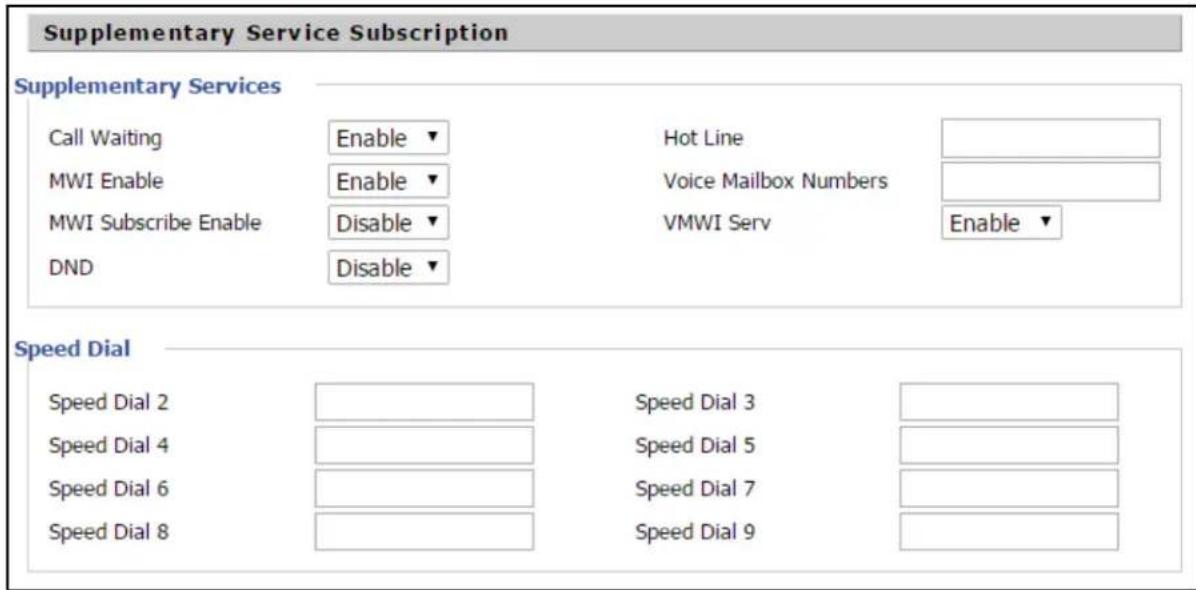
Table 49: Supplementary service
| Field Name Description | |
| Call Waiting | Enable/Disable Call Waiting |
| Hot Line | Fill in the hotline number.Pickup handset or press hands-free or headset button, the device will dial out the hotline number automatically. |
| MWI Enable Enable/Disable MWI (indicates message waiting). If the user needs to user voice mail, please enable this feature. | |
| MWI Subscribe Enable Enable/Disable MWI Subscribe | |
| Voice Mailbox Numbers Fill in the | voice mailbox phone number, Asterisk platform, for example, its default voice mail is *97 |
| VMWI Serv Enable/Disable VMWI | service. |
| DND Enable/Disable DND (do not | disturb).If enable, any phone call cannot arrive at the device; default is disable. |
| Speed Dial Enter the speed dial | phone numbers.Dial *74 to active speed dial function.Then press the speed dial numbers, for example, press 2, phone dials 075526099365 directly. |
Advanced

Table 50: Advanced
| Field Name Description | |
| Domain Name Type If or not use | domain name in the SIP URI. |
| Carry Port Information If or not carry port information in the SIP URI. | |
| Signal Port The local port of SIP protocol, default is 5060. | |
| DTMF Type Choose the DTMF type from Inbound, RFC2833 and SIP INFO. | |
| RFC2833 Payload (>=96) User can | use the default setting. |
| Register Refresh Interval The interval between two normal Register messages. You can use the default setting. | |
| RTP Port Set the port to send RTP. | The device will select one idle port for RTP if you set “O”; otherwise use the value which user sets. |
| Cancel Message Enable When you | set enable, an unregistered message will be sent before registration, while you set disable, unregistered message will not be sent before registration. You should set the option for different Proxy. |
| Session Refresh Time(sec) Time interval between two sessions, you can use the default settings. | |
| Refresher Choose refresher from UAC and UAS. | |
| Prack Enable Enable/Disable prack. | |
| SIP OPTIONS Enable When you set enable, the device will send SIP-OPTION to the server, instead of sending periodic Hello message. The sending interval is Keep-alive interval. | |
| Primary SER Detect Interval Test interval of the primary server, the default value is 0, it represents disable. | |
| Max Detect Fail Count Interval of detection of the primary server fail; the default value is 3, it means that if detect 3 times fail; the device will no longer detect the primary server. | |
| Keep-alive Interval(10-60s) The interval that the device will send an empty packet to proxy. | |
| Anonymous Call Enable/Disable anonymous call. | |
| Anonymous Call Block Enable/Disable anonymous call block. | |
| Proxy DNS Type Set the DNS server type, choose from A type and DNS SRV. | |
| Use OB Proxy In Dialog If or not use OB Proxy In Dialog. | |
| Reg Subscribe Enable If enable, sub-scribing will be sent after registration message, if not enable, do not send subscription. | |
| Dial Prefix | The number will be added before your telephone number when making calls. |
| User Type | Choose the User Type from IP and Phone. |
| Hold Method | Choose the Hold Method from ReINVITE and INFO. |
| Request-URI User Check | Enable/Disable the user request URI check. |
| Only Recv request from server | Enable/Disable the only receive request from server. |
| Server Address | The IP address of SIP server. |
| SIP Received Detection Enable/Disable SIP Received Detection, if enable, use it to confirm the public network address of the device. | |
Preferences
Volume Settings

Table 51: Volume settings
| Field Name Description |
| Handset Input Gain Adjust the handset input gain from 0 |
| Handset Volume Adjust the output gain from 0 to 7. |
to 7.
Regional
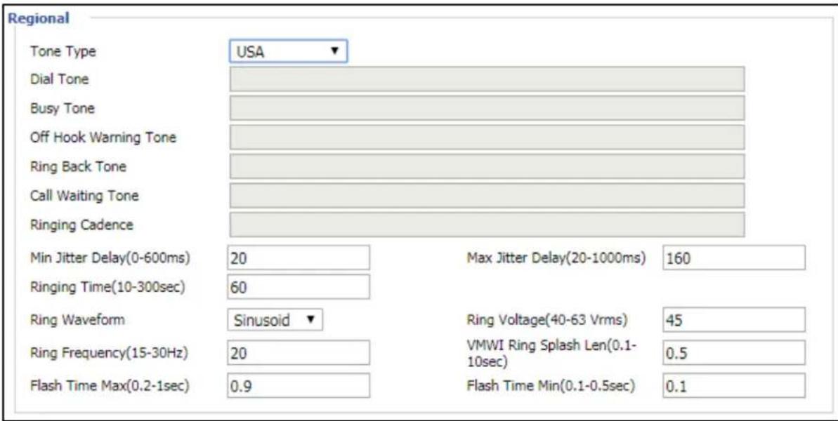
Table 52: Regional
| Field Name Description | |
| Tone Type Choose | tone type as UK, China, US, Hong Kong and so on.A sample Tone Type for UK is shown below: |
| Field Name Description | ||
| COUNTRY/PARAMETER | VALUE | |
| U.K | ||
| Dial tone | 350@-19;440@-19;30(*/0/1+2) | |
| Busy tone | 400@-19;30(.375/.375/1) | |
| Ring Back Tone | 400@-19;450@-19;10(0.4/0.2/1+2,0.4/2.0/1+2) | |
| On-hook Voltage | 50Vrms | |
| Impedance Maching | 370+620||310nF | |
| Ring Voltage | 55Vrms | |
 | NoteCurrently, selecting a particular country does not load the correct Ringing parameters as per standard. If standard based ringing cadence is desired, then the user has to select Custom option for the drop-down list and enter the country specific parameters manually. | |
| Dial Tone Dial Tone | ||
| Busy Tone Busy Tone | ||
| Off Hook Warning Tone | Off Hook warning tone | |
| Ring Back Tone Ring back tone | ||
| Call Waiting Tone | Call waiting tone | |
| Ringing Cadence The ringing pattern heard by the dialer before the called party picks up the | ||
| Min Jitter Delay The Min value of home gateway's jitter delay, home gateway is an adaptive j mechanism | ||
| Max Jitter Delay The Max value of home gateway's jitter delay, home gateway is an adaptive mechanism | ||
| Ringing Time How long cnPilot r190V/r190W/r200/r200P Routers will ring when there is an incoming call | ||
| Ring Waveform Select regional ring waveform, options are Sinusoid and Trapezoid, the default Sinusoid | ||
| Ring Voltage Set ringing voltage, the default value is 70 | ||
| Ring Frequency Set ring frequency, the default value is 25 | ||
| Field Name Description | |
| VMWI Ring Splash Len(sec) | Set the VMWI ring splash length, default is 0.5s |
| Flash Time Max (sec) | Set the Max value of the device's flash time, the default value is 0.9 |
| Flash Time Min (sec) | Set the Min value of the device's flash time, the default value is 0.1 |
Features and Call Forward
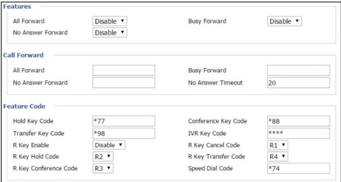
Table 53: Features and call forward
| Field Name Description | ||
| Features | All Forward Enable/Disable forward all calls | |
| Busy Forward Enable/Disable busy forward | ||
| No Answer Forward Enable/Disable no answer forward | ||
| Call Forward | All Forward Set the target phone number for all forward.The device will forward all calls to the phone number immediately when there is an incoming call. | |
| Busy Forward The phone number which the calls will be forwarded to when line is busy | ||
| No Answer Forward The | phone number which the call will be forwarded to when there's no answer | |
| No Answer Timeout The | seconds to delay forwarding calls, if there is no answer at your phone | |
| Feature Code | Hold key code Call hold | signatures, default is *77 |
| Conference key code S | signature of the tripartite session, default is *88 | |
| Transfer key code Call | forwarding signatures, default is *98 | |
| IVR key code Signatures | of the voice menu, default is **** | |
| R key enable Enable/Dis | able R key way call features | |
| R key cancel code Set | the R key cancel code, options are ranged from R1 to R9, default value is R1 | |
| R key hold code Set the | R key hold code, options are ranged from R1 to R9, default value is R2 | |
| R key transfer code Set | the R key transfer code, options are ranged from R1 to R9, default value is R4 | |
| R key conference code | Set the R key conference code, options are ranged from R1 to R9, default value is R3 | |
| Speed Dial Code Speed | dial code, default is *74 | |
Miscellaneous
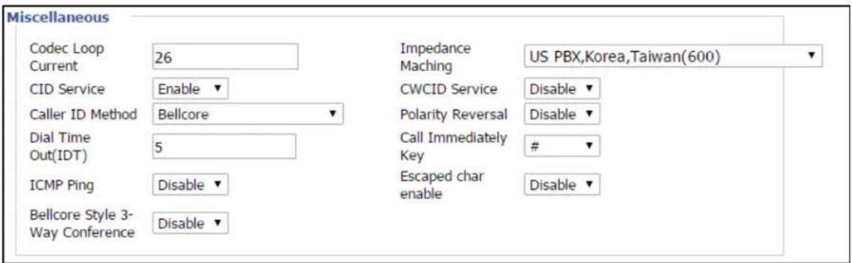

Warning
3-wire connection is not supported.
Table 54: Miscellaneous
| Field Name Description | |
| Codec Loop Current | Set off-hook loop current, default is 26 |
| Impedance Matching | Set impedance matching, default is US PBX, Korea, Taiwan (600) |
| CID service Enable/ | Disable displaying caller ID; If enable, caller ID is displayed when there is an incoming call or it won't be displayed. Default is Enable |
| CWCID Service Enable/ | Disable/Disable CWCID. If enable, the device will display the waiting call's caller ID, or it won't display. Default is Disable |
| Dial Time Out How | long cnPilot Home Router will sound dial out tone |
| Call Immediately Key | Choose call immediately key form * or # |
| ICMP Ping Enable/ | Disable ICMP Ping.If enable this option, home gateway will ping the SIP Server every interval time, otherwise, It will send “hello” empty packet to the SIP Server. |
| Escaped char enable | Open special character translation function; if enable, when you press the # key, it will be translated to 23%, when disable, it is just # |
FXS2
The settings of FXS2 are the same as FXS1. See FXS1 on page FXS1.
Voice calls
Making a call
Calling phone or extension numbers
To make a phone or extension number call:
- Both ATA and the other VoIP device (such as another ATA or other SIP products) must have public IP addresses, or
- Both ATA and the other VoIP device (such as another ATA or other SIP products) are on the same LAN using private or public IP addresses, or
- Both ATA and the other VoIP device (such as another ATA or other SIP products) can be connected through a router using a public or private IP addresses.
To make a call, pick up the analog phone or turn on the speakerphone on the analog phone, enter the extension or phone number directly, end with #.
Direct IP calls
Direct IP calling allows two phones, that is, an ATA with an analog phone and another VoIP Device, to talk to each other without a SIP proxy. VoIP calls can be made between two phones if:
- Both ATA and the other VoIP device (such as another ATA or other SIP products) have public IP addresses, or
- Both ATA and the other VoIP device (such as another ATA or other SIP products) are on the same LAN using private or public IP addresses, or
- Both ATA and the other VoIP device (such as another ATA or other SIP products) can be connected through a router using public or private IP addresses.
To make a direct IP call, pick up the analog phone or turn on the speakerphone on the analog phone, Input the IP address directly, with the end “#”.
Call hold
While in conversation, pressing the “*77” to put the remote end on hold, then you hear the dial tone and the remote party hears hold tone at the same time.
Press “*77” again to release the previously hold state and resume the bi-directional media.
Blind transfer
Assume that call party A and party B are in conversation. Party A wants to Blind Transfer B to C then:
- Party A dials “*78” to get a dial tone, then dials party C's number, and then press immediately key # (or wait for 4 seconds) to dial out.
- A can hang up.
Attended transfer
Assume that call party A and B are in a conversation. A want to Attend Transfer B to C:
- Party A dials “*77” to hold the party B, when hear the dial tone, A dials C’s number, then party A and party C are in conversation.
- Party A dials “*78” to transfer to C, then B and C now in conversation.
- If the transfer is not completed successfully, then A and B are in conversation again.
Conference
Assume that call party A and B are in a conversation. A want to add C to the conference:
- Party A dials “*77” to hold the party B, when hear the dial tone, A dial C’s number, then party A and party C are in conversation.
- Party A dials “*88” to add C, then A and B, for conference.
Security
Filtering Setting

Table 55: Filtering setting
| Field Name Description | |
| Filtering Enable/Disable filter function | |
| Default Policy Choose to drop or accept filtered MAC addresses | |
| Mac address Add the Mac address filtering | |
| Dest IP address Destination IP address | |
| Source IP address Source IP address | |
| Protocol Select a protocol name, support for TCP, UDP and TCP/UDP | |
| Dest. Port Range Destination port ranges | |
| Src Port Range Source port range | |
| Action You can choose to accept or drop; this should be consistent with the default policy. | |
| Field Name Description | |
| Comment Add callout | |
| Delete Delete selected item | |
Content Filtering
Table 56: Content filtering
| Basic Settings | |
| Filtering | Disable ▼ |
| Default Policy | Drop ▼ |
| The packet that don't match with any rules would be Drop | |
| Save Cancel | |
| IP/Port Filter Settings | |
| Interface | LAN ▼ |
| Mac address | LAN |
| Dest IP Address | WAN |
| Source IP Address | |
| Protocol | NONE ▼ |
| Dest. Port Range | |
| Src Port Range | |
| Action | Accept ▼ |
| Comment | |
| (The maximum rule count is 32 ) | |
| Save Cancel | |
| Field Name Description | |
| Filtering Enable/Disable content | Filtering |
| Default Policy The default policy is to accept or to prohibit filtering rules | |
| Current Webs URL Filters List | the URL filtering rules that already existed (blacklist) |
| Delete/Cancel You can choose | to delete or cancel the existing filter rules |
| Add a URL Filter Add URL filtering rules | |
| Add/Cancel Click adds to add | one rule or click cancel |
| Current Website Host Filters List | list the keywords that already exist (blacklist) |
| Delete/Cancel You can choose | to delete or cancel the existing filter rules the existing keywords |
| Add a Host Filter (Keyword) | Add keywords |
| Add/Cancel Click the Add or | cancel |
Application
UPnP
UPnP (Universal Plug and Play) supports zero-configuration networking and can automatically discover a variety of networked devices. When UPnP is enabled, the connected device can access the network, obtain an IP address, and convey performance information. If the network has a DHCP and DNS server, the connected device can automatically obtain DHCP and DNS services.
UPnP devices can be automatically added to the network without affecting previously connected devices.

Table 57: UPnP
| Field Name Description | |
| UPnP enable Enable/Disable UPnP function. | |
IGMP
Multicast has ability to send the same data to multiple devices.
IP hosts use IGMP (Internet Group Management Protocol) report multicast group memberships to the neighboring routers to transmit data, at the same time, the multicast router use IGMP to discover which hosts belong to the same multicast group.
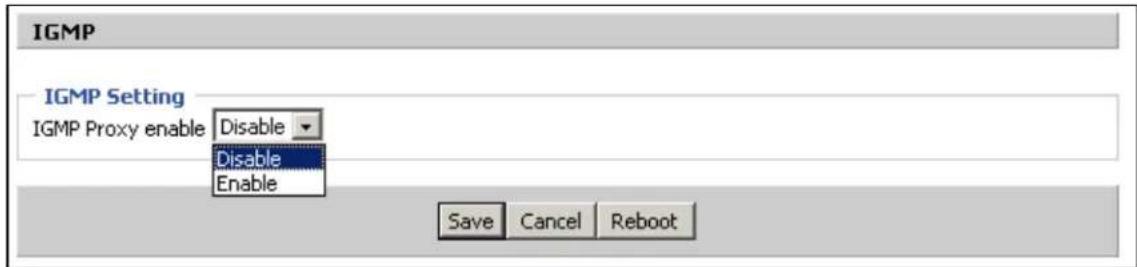
Table 58: IGMP
| Field Name Description | |
| IGMP Proxy enable | Enable/Disable IGMP function. |
Storage
Disk Management
The Disk Management page is used to manage the USB storage devices.
Chapter 3: Advanced Configuration 102

Table 59: Disk Management
| Field Name Description |
| Add Adding files to the USB storage device |
| Delete Remove the USB storage device file |
| Remove Disk Transfer files within a USB storage device |
| Format Format the USB storage device |
| Re-allocate Reset the USB storage device |

Note
Only FAT/FAT32 USB drive formats are supported. Other file systems like NTFS/EXT2/EXT3 will not be detected.
FTP Setting

Table 60: FTP Setting
| Field Name Description | |
| FTP Server Enable/Disable FTP server | |
| FTP Server Name Set | the FTP server name |
| Anonymous Login If or not support anonymous login | |
| FTP Port Set FTP server port number | |
| Max. Sessions Maximum number of connections | |
| Create Directory Enable/Disable create directory | |
| Rename File/Directory | Enable/Disable rename file/directory |
| Remove File/Directory | Enable/Disable transfer of files/directories |
| Read File Enable/Disable read files | |
| Write File Enable/Disable write files | |
| Download Capability | Enable/Disable download capability function. |
| Upload Capability | Enable/Disable upload capability function |
Smb Setting
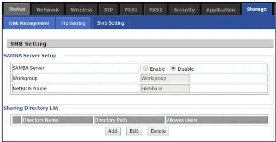
Table 61: Smb setting
| Field Name Description | |
| SAMBA Server | Enable/Disable SAMBA server |
| Workgroup Enter the working group | |
| NetBIOS Name | Network basic input/output system nan |
| Add Add a shared file | |
| Edit Edit a shared file | |
| Del Delete a shared file | |
| Add Add a shared file | |
| Edit Edit a shared file | |
| Del Delete a shared file | |
Administration
The Administration page is used to manage the device. You can configure the Time/Date, password, web access, system log, and associated configuration TR069.
Management
Save Config File

Table 62: Save Config File
| Field Name Description | |
| Config file upload and download | Upload: Click browse and select file in the local. Press the Upload button to begin uploading files. |
| Download: Click Download and select the path to download the configuration file. |
Administrator settings
Table 63: Administrator settings
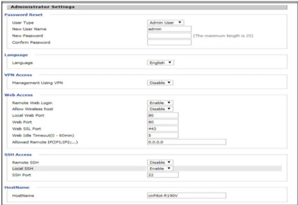

| Field Name Description | |
| User type Choose the user type from admin user and normal user and basic user. | |
| New User Name You can modify the user name, set up a new user name. | |
| New Password Input the new password. | |
| Confirm Password Input the new password again. | |
| Language Select the language for the web, the device supports the languages such as Chinese, English, and Spanish. | |
| Management using VPN | |
| Remote Web Login Enable/Disable remote Web login. | |
| Allow wireless host To allow all the wireless clients connected to the cnPilot Home Router to the management interface. | |
access
| Field Name Description | |
| Local Web Port Set | the port value which is used to login from Internet port and PC port, default is 80. |
| Web Idle timeout Set | the Web Idle timeout time. The webpage can be logged out after Web Idle Timeout without any operation. |
| Allowed Remote IP (IP1, IP2,...) | Set the IP from which a user can login the device remotely. |
| SSH Enable/Disable telnet. | |
Enabling Mangement access for wireless clients
To allow all the wireless clients connected to the cnPilot Home Router to access the management interface:
- Navigate to Administrator tab.
- Enable Allow Wireless Host option under Web Access.
The user must have administrator permissions to make this change.
Enabling SNMP access over WAN
To enable SNMP access over WAN:
- Navigate to Administrator > SNMP tab.
- Enable Remote SNMP Login option.
The user must have administrator permissions to make this change.
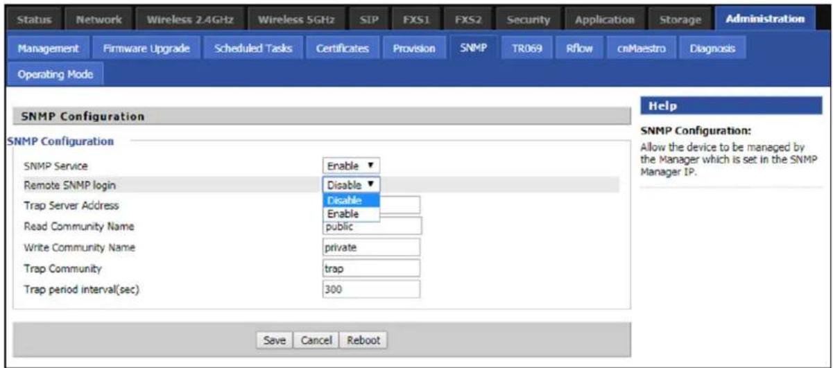
NTP settings

Table 64: NTP settings
| Field Name Description | |
| NTP Enable Enable/Dis | sable NTP |
| Option 42 Enable/Dis | able DHCP option 42. This option specifies a list of the NTP servers available to the client by IP address |
| Current Time Display | current time |
| NTP Settings Setting | the Time Zone |
| Primary NTP Server | Primary NTP server's IP address or domain name |
| Secondary NTP Server | Options for NTP server's IP address or domain name |
| NTP synchronization | NTP synchronization cycle, cycle time can be 1 to 1440 minutes in anyone default setting is 60 minutes |
Daylight Saving Time

Table 65: Daylight Saving Time
| Steps | Procedure |
| 1 Enable | Daylight Savings Time. |
| 2 Set value of offset for Daylight Savings Time | |
| 3 Set starting Month/Week/Day/Hour in Start Month/Start Day of Week Last in Month/Start Day of Week/Start Hour of Day, analogously set stopping Month/Week/Day/Hour in St Month/Stop Day of Week Last in Month/Stop Day of Week/Stop Hour of Day. | |
| 4 Press | Saving button to save and press Reboot button to active changes. |
System Log Setting
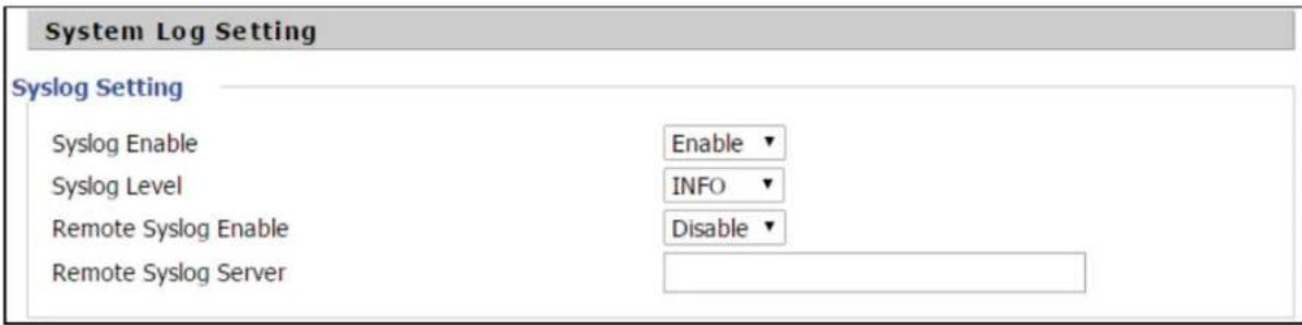
Table 66: System log Setting
| Field Name Description | |
| Syslog Enable Enable/Disable syslog function | |
| Syslog Level Select | the system log, there is INFO and Debug two grades, the Debug INFO ca provide more information. |
| Remote Syslog Enable | Enable/Disable remote syslog function. |
| Remote Syslog server | Add a remote server IP address. |
| Syslog Enable Enable/Disable syslog function | |
| Syslog Level Select | the system log, there is INFO and Debug two grades, the Debug INFO can provide more information. |
Factory Defaults Setting

Table 67: Factory Defaults Setting
| Description |
| With this lock enabled, user cannot factory reset the box using the hardware switch. |
Factory Defaults

Table 68: Factory Defaults
| Description |
| Click Factory Default to restore the cnPilot Home Router to factory settings. |
Firmware upgrade
This page is used to upgrade the device Firmware.
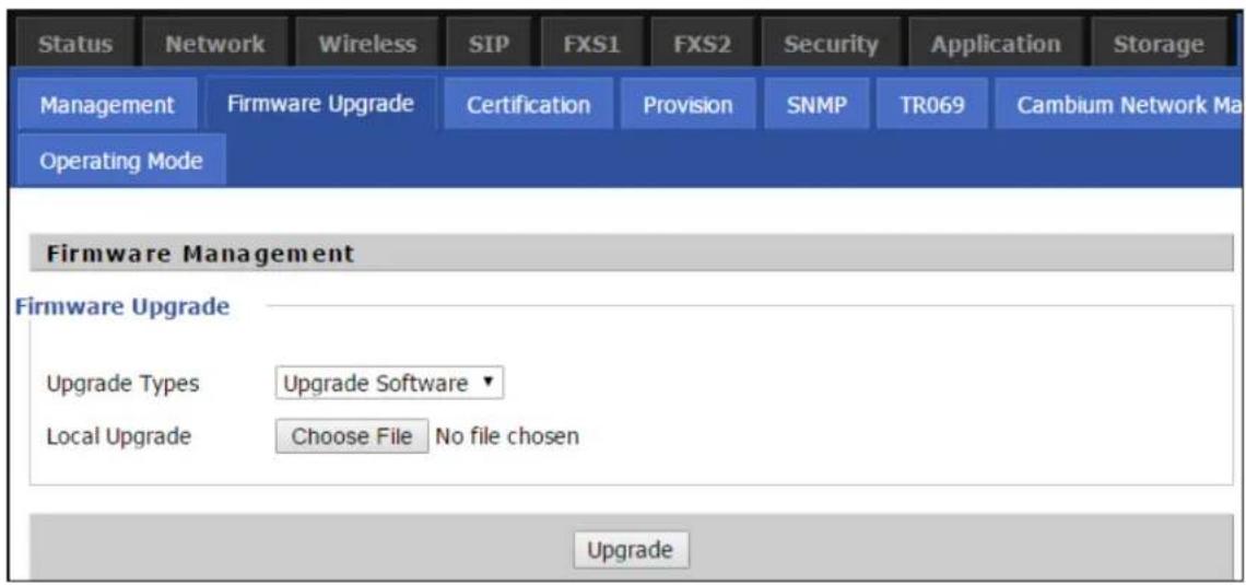
Table 69: Firmware upgrade
| Description |
| Select upgrade file type from Image File and Dial |
| Click Browse to browse the file. |
| Click to start upgrading |
Rule.

Note
Firmware cannot be downgraded to below 4.7.2, for the devices with OUI BC:A9:93 and later MAC address.
Provision
Provisioning allows cnPilot Home Router to auto-upgrade and auto-configure devices which support TFTP, HTTP and HTTPS.
- Before testing or using TFTP, user should have tftp server and upgrading file and configuring file.
- Before testing or using HTTP, user should have http server and upgrading file and configuring file.
- Before testing or using HTTPS, user should have https server and upgrading file and configuring file and CA Certificate file (should same as https server's) and Client Certificate file and Private key file
User can upload a CA Certificate file and Client Certificate file and Private Key file in the Security page.

Table 70: Provision
| Field Name Description | |
| Provision Enable Enable provision or not | |
| Resync on Reset Enable re-sync after restart or not | |
| Resync Random Delay(sec) Set the | maximum delay for the request of synchronization file. The default is 40 |
| Resync Periodic(sec) If the last res | sync was failure, cnPilot r190V/r190W/r200/r200P Routers will retry resync after the “Resync Error Retry Dela time, default is 3600s |
| Resync Error Retry Delay(rec) Set | the periodic time for resync, default is 3600s |
| Forced Resync Delay(sec) If it's time to resync, but cnPilot r190V/r190W/r200/r200P Router is busy now, in this case, cnPilot r190V/r190W/r200/r200P Router will wait for a period time the longest is “Forced Resync Delay”, default is 14400s, with the time over, cnPilot r190V/r190W/r200/r200P Router will forced to re-sync | |
| Resync After Upgrade Enable firmware upgrade after re-sync or not. The default is Enabled | |
| Resync From SIP Enable/Disable re | -sync from SIP |
| Option 66 It is used for In-house | provision mode only. When use TFTP with option 66 to realize provisioning, user must input right configuration file name in the web page. When disable Option 66, this parameter has no effect |
| Config File Name It is used for In-house | house provision mode only. When use TFTP with option 66 to realize provisioning, user must input right configuration file name in the web page. When disable Option 66, this parameter has no effect |
| Profile Rule URL of profile provision file | Note that the specified file path is relative to the TFTP server's virtual root directory. |
Firmware Upgrade
Upgrade Enable
Upgrade Error Retry Delay(sec)
Upgrade Rule
Enable ▼
3600
Table 71: Firmware Upgrade
| Field Name Description | |
| Upgrade Enable | Enable firmware upgrade via provision or not |
| Upgrade ErrorRetry Delay(sec) | If the last upgrade fails, cnPilot r190V/r190W/r200/r200P Routers will try upgrading again after “Upgrade Error Retry Delay” period, default is 3600s |
| Upgrade Rule URL of upgrade file | |
SNMP
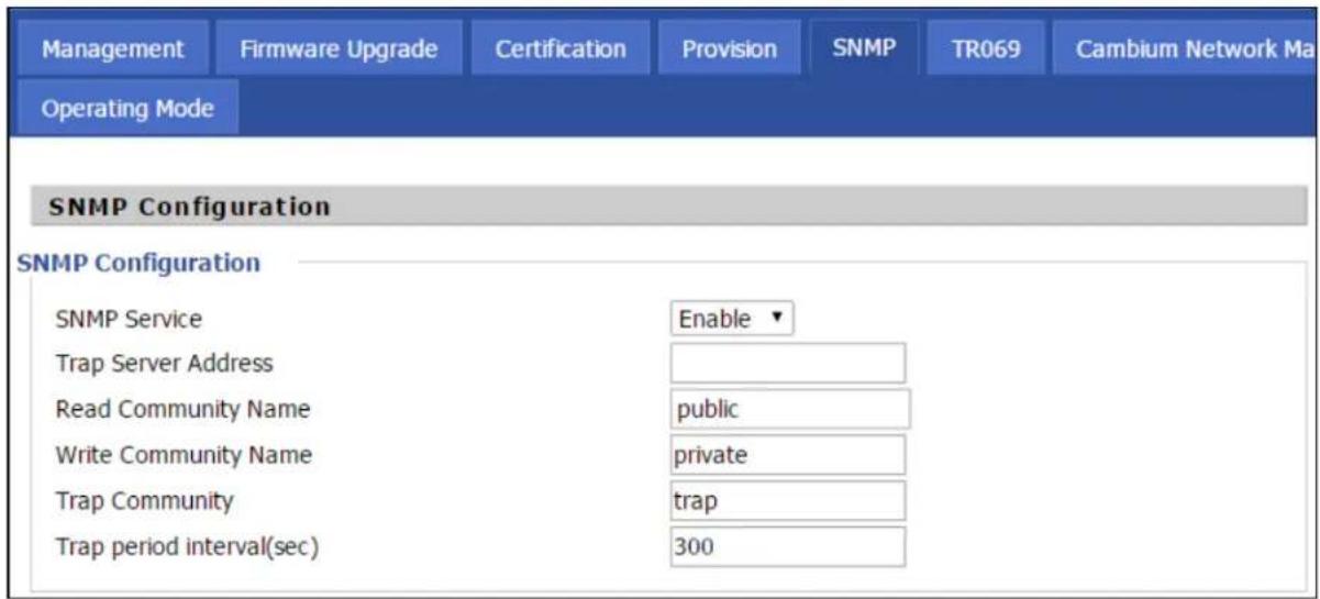
Table 72: SNMP
| Field Name Description | |
| SNMP Service Enable | or Disable the SNMP service |
| Trap Server Address | Enter the trap server address for sending SNMP traps |
| Read Community Name | String value that is used as a password to request information via SNMP from the device |
| Write Community Name | String value that is used as a password to write configuration values to the device via SNMP |
| Trap Community String value used as a password for retrieving traps from the device | |
| Trap period interval (sec) | The interval for which traps are sent from the device |
TR-069
TR-069 provides the possibility of auto configuration of internet access devices and reduces the cost of management. TR-069 (short for Technical Report 069) is a DSL Forum technical specification entitled CPE WAN Management Protocol (CWMP). It defines an application layer protocol for remote management of end-user devices. Using TR-069, the terminals establish connection with the Auto Configuration Servers (ACS) and get configured automatically.
Device Configuration using TR-069
The TR-069 configuration page is available under Administration menu.

Table 73: TR069
| Field Name Description | |
| ACS parameters | |
| TR069 Enable Enable | or Disable TR069 |
| CWMP Enable or Disable | CWMP |
| ACS URL ACS URL address | |
| User Name ACS username | |
| Password ACS password | |
| Periodic Inform Enable | Enable the function of periodic inform or not. By default, it is Enabled. |
| Periodic Inform Interval | Periodic notification interval with the unit in seconds. The default value 43200s. |
| Connect Request parameters | |
| User Name The username | name used to connect the TR069 server to the DUT. |
| Password The password | used to connect the TR069 server to the DUT. |
TR-069 Profile
Under nodes base on TR098, TR104 and TR111.
{"InternetGatewayDevice", }, {"DeviceSummary", }, {"LANDeviceNumberOfEntries", }, {"WANDeviceNumberOfEntries", }, {"DeviceInfo", }, {"Manufacturer", }, {"ManufacturerOUI", }, {"ModelName", }, {"Description", }, {"ProductClass", }, {"SerialNumber", }, {"HardwareVersion", }, {"SoftwareVersion", }, {"SpecVersion", }, {"ProvisioningCode", }, {"UpTime", }, {"DeviceLog", },{{{ "", },}
{"ManagementServer", }, {"URL", }, {"Username", }, {"Password", }, {"PeriodicInformEnable", }, {"PeriodicInformInterval", }, {"PeriodicInformTime", }, {"ParameterKey", }, {"ConnectionRequestURL", }, {"ConnectionRequestUsername", }, {"ConnectionRequestPassword", }, {"UpgradesManaged", }, {"UDPConnectionRequestAddress", },
{"UDPConnectionRequestAddressNotificationLimit", },
{"STUNEnable", },
{"STUNServerAddress", },
{"STUNServerPort", },
{"STUNUsername", },
{"STUNPassword", },
{"STUNMaximumKeepAlivePeriod", },
{"STUNMinimumKeepAlivePeriod", },
{"NATDetected", },
{{{",}},
{"UPnP", },
{"Device", },
{"UPnPIGD", },
{{{",}},
{{{",}},
{"IPPingDiagnostics", },
{"DiagnosticsState", },
{"Interface", },
{"Host", },
{"NumberOfRepetitions", },
{"Timeout", },
{"DataBlockSize", },
{"DSCP", },
{"SuccessCount", },
{"FailureCount", },
{"AverageResponseTime", },
{"MinimumResponseTime", },
{"MaximumResponseTime", },
{{{",}},
{"DownloadDiagnostics", },
{"DiagnosticsState", }, {"Interface", }, {"DownloadURL", }, {"DSCP", }, {"EthernetPriority", }, {"ROMTime", }, {"BOMTime", }, {"EOMTime", }, {"TestBytesReceived", }, // {"TotalBytesReceived", }, {"TCPOpenRequestTime", }, {"TCPOpenResponseTime", },{{{ "", },}
{"UploadDiagnostics", },
{"DiagnosticsState", },
{"Interface", },
{"UploadURL", },
{"DSCP", },
{"EthernetPriority", },
{"TestFileLength", },
{"ROMTime", },
{"BOMTime", },
{"EOMTime", },
// {"TotalBytesSent", },
{"TCPOpenRequestTime", },
{"TCPOpenResponseTime", },
{{{ "",}},
Under is firmware upgrading operation on FreeACS.
Equipment connection configure

Scheduled Tasks
In this page, the user can set time to automatically turned ON or OFF the Wi-Fi, Reboot, or restart PPPoE at a moment.
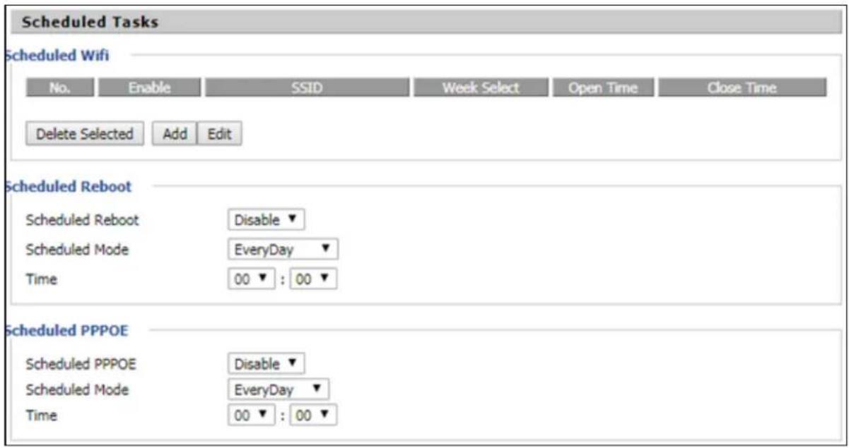
Chapter 3: Advanced Configuration 132
Table 74: Scheduled Tasks
| Field Name | Description |
| Scheduled Wi-Fi | Select the Wi-Fi and click Edit to set the timings |
| Scheduled Reboot | Set values for Scheduled Reboot, Scheduled Mode, and Time |
| Scheduled PPPoE | Set values for Scheduled PPPoE, Scheduled Mode, and Time |
Diagnosis
In this page, user can do packet trace, ping test and traceroute test to diagnose the device's connection status.

Table 75: Diagnosis
| Description |
| Packet TraceUsers can use the packet trace feature to intercept packets which traverse the device. Click t button to start home gateway tracking and keep refreshing the page until the message trace stop, click the Save button to save captured packets. |
| Ping Test |
Description
Enter the destination IP or host name, and then click Apply, device will perform ping test.
Ping Test
Traceroute Test
Ping Test
Ping Test
Dest IP/Host Name
WAN Interface

1_TR069_VOICE_INTERNET_R_VID_
PING www.baidu.com (115.239.210.26): 56 data bytes
64 bytes from 115.239.210.26: seq=0 ttl=54 time=43.979 ms
64 bytes from 115.239.210.26: seq=1 ttl=54 time=53.875 ms
64 bytes from 115.239.210.26: seq=2 ttl=54 time=45.226 ms
64 bytes from 115.239.210.26: seq=3 ttl=54 time=49.534 ms
64 bytes from 115.239.210.26: seq=4 ttl=54 time=49.045 ms
--- www.baidu.com ping statistics ---
5 packets transmitted, 5 packets received, 0% packet loss
round-trip min/avg/max = 43.979/48.331/53.875 ms
Apply
Cancel

Traceroute Test
Enter the destination IP or host name, and then click Apply, device will perform traceroute test.
Traceroute Test
Traceroute Test
Dest IP/Host Name
www.google.com
WAN Interface
1_MANAGEMENT_VOICE_INTERNET_R_VID_
traceroute to www.google.com (216.58.208.68), 30 hops max, 38 byte packets
1 10.110.134.254 (10.110.134.254) 1.017 ms 9.507 ms 1.419 ms

Apply
Cancel

Operating Mode

Table 76: Operating mode
| Description |
| Choose the Operation Mode as Basic Mode or Advanced Mode (Default).In Basic mode, multi WAN configuration is not allowed and the device can be configured either simple NAT or Bridge device. |
System Log
| Status | Network | Wireless | SIP | FXS1 | FXS2 | Security | Application | Storage | Administration |
| Basic | LAN Host | Syslog | |||||||
| Refresh | Clear | Save | |||||||
| Manufacturer:CAMBIUM NETWORKSProductClass:C3VoIP-200PSerialNumber:400FQU001GLXBuildTime:201506180103IP:192.168.11.1HWVer:V1.3SWVer:3.10-b1 | |||||||||
Table 77: System log
| Description |
| If you enable the system log in Status/syslog webpage, you can view the system log in this webpage. |
Logout
![Cambium Networks Status Network Wireless SIP FXS1 FXS2 Security Application Storage Administration Management Firmware Upgrade Certification Provision SNMP/TR069 Cambium Network Manager Diagnosis Firmware Version 3.10 Current Time 2015-06-15 17:32:00 Admin Mode [Logout] [Reboot]](/content/2026/05/1044932/images/4ebadaab5dea7182a8b50200fc21d12c3e250e11fda4eec18dc4abcfc7132770.jpg)
Table 78: Logout
| Description |
| Press the logout button to logout, and then the login window will appear. |
Reboot
Press the button to reboot cnPilot Home Routers.
Chapter 4: Troubleshooting
This chapter contains the following topics:
- Configuring PC to get IP Address automatically
- Cannot connect to the Web GUI
• Forgotten Password
• cnMaestro On-boarding troubleshooting
Configuring PC to get IP Address automatically
Refer the Quick Start Guide to configure your PC to get IP Address automatically.
Cannot connect to the Web GUI
If Web GUI is not getting connected, then perform the following steps:
- Check if the Ethernet cable is properly connected.
- Connect to LAN port and access https://192.168.11.1 or http://192.168.11.1. Check on any other browser other than Internet Explorer, such as Firefox or Mozilla.
- Contact your administrator, supplier or ISP for more information or assistance.
Forgotten Password
The default password is admin/admin user/user. If it is changed to non-default, then factory reset may be required.

Note
On factory reset, all the device configurations are reset to the default.
Solution:
To factory default reset, press and hold reset button for 10 seconds.
If device is onboarded in cnMaestro then password can be set through config push.
cnMaestro On-boarding troubleshooting
The On-boarding troubleshooting procedure is described below:
- During the Cambium ID on boarding, if the device dashboard or home page displays the cnMaestro connection status as the following:
| Error Status Cause | Resolution | |
| Failed to Resolve URL | The cloud URL is not being resolved by the device. | Ensure that the correct cnMaestro URL is configured.If the URL is correct, check the DNS settings and Internet connectivity.If the Internet connectivity and DNS works then check the firewall configuration for device IP Address and the protocols http/https/SSL are allowed as part of ACL. |
| Invalid Cambium ID/Password | Wrong configuration of cambium ID or On Boarding key | Ensure that the correct credentials are entered. |
| Invalid Cookie or Cambium ID not configured | Device is unclaimed Claim | In the device either by serial number or Cambium ID |
| Device Not Claimed | Device is not claimed Claim | In the device either by serial number or Cambium ID |
| Connecting Device | Is trying to connect to the cnMaestro server | Device is in connecting state |
- During the serial number on boarding, following are the error messages:
| Error Status Cause | Resolution | |
| Unknown Device | Device serial number is not known to cnMaestr server | Send a mail to solutions@cambiumnetworks.com for the serial numbers to be added to the server database. |
| Invalid Serial Number | Device serial number is less than 12 characters and given for claiming | Enter the correct serial number of the device or try on boarding using Cambium ID. |
| Already Managed by this account | Device is already managed by the current user account | Do not try both the serial number and cambium ID on boarding methods at the same time. |
| Already Managed by other Account | Device is already claimed in another user account | Ensure that the entered serial number of device belongs to current user account. |
After the error messages occurs, click OK on the error dialog and then verify the serial numbers by entering correct values and initiate the claiming procedure.
Else, you can clear the wrong serial numbers if it need not to be claimed. This allows you not to re-enter serial number again and remove the invalid characters from entered serial number.
- cnMaestro Account ID is the Cambium ID or Account Name chosen while creating the company account which indicates that the device belongs to that account. cnMaestro Account ID is blank
when the device is not claimed and populated when the device is claimed in the cnMaestro server. The Account ID is available in the device dashboard or home page.
Appendix: Third Party Software
The software may contain one or more items of Third-Party Software supplied by other third-party suppliers. The terms of this Agreement govern your use of any Third-Party Software license is included, in which case your use of the unless a separate third-party software license is included, in which case your use of the third-party software will then be governed by the separate third-party license.
Zap
copyright (c) 2004-2009, Ruckus Wireless, Inc.
All rights reserved.
Redistribution and use in source and binary forms, with or without modification are permitted provided that the following conditions are met:
* Redistributions of source code must retain the above copyright notice, this list of conditions and the following disclaimer.
* Redistributions in binary form must reproduce the above copyright notice, this list of conditions and the following disclaimer in the documentation and/or other materials provided with the distribution.
* Neither the name of Ruckus Wireless nor the names of its contributors may be used to endorse or promote products derived from this software without specific prior written permission.
THIS SOFTWARE IS PROVIDED BY THE COPYRIGHT HOLDERS AND CONTRIBUTORS "AS IS" AND ANY EXPRESS OR IMPLIED WARRANTIES, INCLUDING, BUT NOT LIMITED TO, THE IMPLIED WARRANTIES OF MERCHANTABILITY AND FITNESS FOR A PARTICULAR PURPOSE ARE DISCLAIMED. IN NO EVENT, SHALL COPYRIGHT HOLDER OR CONTRIBUTORS BE LIABLE FOR ANY DIRECT, INDIRECT, INCIDENTAL, SPECIAL, EXEMPLARY, OR CONSEQUENTIAL DAMAGES (INCLUDING, BUT NOT LIMITED TO, PROCUREMENT OF SUBSTITUTE GOODS OR SERVICES; LOSS OF USE, DATA, OR PROFITS; OR BUSINESS INTERRUPTION) HOWEVER CAUSED AND ON ANY THEORY OF LIABILITY, WHETHER IN CONTRACT, STRICT LIABILITY, OR TORT (INCLUDING NEGLIGENCE OR OTHERWISE) ARISING IN ANY WAY OUT OF THE USE OF THIS SOFTWARE, EVEN IF ADVISED OF THE POSSIBILITY OF SUCH DAMAGE.
Appendix: Part Numbers
Manufacturer: Cambium Networks Inc.
Address: 3800 Golf Road #360, Rolling Meadows, IL 60008 USA.
Importers:
Address:
Adapter Caution: Adapter shall be installed near the equipment and shall be easily accessible.
The following tables provides accessories details for cnPilot Home Routers:
Appendix: Part Numbers
The software may contain one or more items of Third-Party Software supplied by other third-party suppliers. The terms of this Agreement govern your use of any Third-Party Software license is included, in which case your use of the unless a separate third-party software license is included, in which case your use of the third-party software will then be governed by the separate third-party license.
Part Numbers for cnPilot r195P Home Router
| Part Number Description | AC Power Cord Part | Number |
| PL-r195PUSA-US Home | and Small Business Wi-Fi Router and Voice Gateway, 802.11AC with Cambium power out, US | N000900L040A |
| PL-r195PEUA-EU Home | and Small Business Wi-Fi Router and Voice Gateway, 802.11AC with Cambium power out, EU | N000900L041A |
| PL-r195PEUA-RW Home | and Small Business Wi-Fi Router and Voice Gateway, 802.11AC with Cambium power out, RW | N000900L041A |
| PL-r195PNPA-RW Home | and Small Business Wi-Fi Router and Voice Gateway, 802.11AC with Cambium power out, RW | - |
| PL-r195PUKA-EU Home | and Small Business Wi-Fi Router and Voice Gateway, 802.11AC with Cambium power out, EU | N000900L045A |
| PL-r195PINA-RW Home | and Small Business Wi-Fi Router and Voice Gateway, 802.11AC with Cambium power out, RW | N000900L043A |
| PL-r195PANA-RW Home | and Small Business Wi-Fi Router and Voice Gateway, 802.11AC with Cambium power out, RW | N000900L042A |
| PL-r195PNTA-RW Home | and Small Business Wi-Fi Router and Voice Gateway, 802.11AC with Cambium power out, RW | N000900L044A |
| PL-r195PARA-RW Home | and Small Business Wi-Fi Router and Voice Gateway, 802.11AC with Cambium power out, RW | N000900L047A |
Part Numbers for cnPilot r195W Home Router
| Part Number Description | 12V 1A Wall Adaptor | |
| PL-R195WUSA-US r195W US type A P/S, 802.11n/AC Dual Band 2x2 WLAN access point | XA-PS12V1XA-US | |
| PL-R195WEUA-EU | r195W EU type C P/S, 802.11n/AC Dual Band 2x2 WLAN access point | WLA-PS12V1XA-EU |
| PL-R195WNPA-RW | r195W No line cord, 802.11n/AC Dual Band 2x2 WLAN access point | AN |
| PL-R195WUKA-EU | r195W UK type G P/S, 802.11n/AC Dual Band 2x2 WLAN access point | XA-PS12V1XA-UK |
| PL-R195WINA-RW r19 | 5W India type D P/S, 802.11n/AC Dual Band 2x2 WLAN access point | XA-PS12V1XA-IN |
| PL-R195WANA-RW r19 | 95W AUS/NZ type I P/S, 802.11n/AC Dual Band 2x2 WLAN access point | XA-PS12V1XA-AN |
| PL-R195WNTA-RW r19 | 95W Brazil type N P/S, 802.11n/AC Dual Band 2x2 WLAN access point | XA-PS12V1XA-NT |
| PL-R195WARA-RW r19 | 95W Argentina type I P/S 802.11n/AC Dual Band 2x2TBD WLAN access point | |
Part Numbers for cnPilot r200, r200P Home Routers
| Part Number Description 12V 2A Wall Mount | or 12V 3A Desktop Adaptor | |
| C000000L024A cnPilot r200 US, 802.11n single band 300Mbps WLAN Router with ATA | XA-PS2AWPGA-US | |
| C000000L025A cnPilot r200 EU, 802.11n single band 300Mbps WLAN Router with ATA | XA-PS2AWPGA-EU | |
| C000000L037A cnPilot r200 AUS, 802.11n single band 300Mbps WLAN Router with ATA | XA-PS3ADTA-WW | |
| C000000L038A cnPilot r200 India, 802.11n single band 300Mbps WLAN Router with ATA | XA-PS3ADTA-WW | |
| C000000L039A cnPilot r200 Brazil, 802.11n single band 300Mbps WLAN Router with ATA | XA-PS3ADTA-WW | |
| PL-R200XUKA-WW | cnPilot r200 (UK cord) 802.11n single band WLAN Rout with ATA | XA-PS3ADTA-WW |
| PL-R200XCNA-WW | cnPilot r200 (China cord) 802.11n single band WLAN Router with ATA | XA-PS3ADTA-WW |
| PL-R200XARA-WW | cnPilot r200 (Argentina cord) 802.11n single band WLAN Router with ATA | XA-PS3ADTA-WW |
Part Numbers for cnPilot R201, R201P Home Routers
| Part Number Description 12V 2A wall mount | or 12V 3A Desktop Adaptor | |
| C000000L029A | cnPilot r201 EU, 802.11ac dual band Gigabit WLAN Router with ATA | XA-PS2AWPGA-US |
| C000000L040A | cnPilot r201 AUS, 802.11ac dual band Gigabit WLAN Router with ATA | XA-PS2AWPGA-EU |
| C000000L041A cn | Pilot r201 India, 802.11ac dual band Gigabit WLAN Router with ATA | XA-PS3ADTA-WW |
| C000000L042A cn | Pilot r201 Brazil, 802.11ac dual band Gigabit WLAN Router with ATA | XA-PS3ADTA-WW |
| PL-R201XUKA-WW | cnPilot r201 (UK cord) 802.11ac dual band WLAN Router with ATA | XA-PS3ADTA-WW |
| PL-R201XCNA-WW | cnPilot r201 (China cord) 802.11ac Dual band WLAN Router with ATA | XA-PS3ADTA-WW |
| PL-R201XARA-WW | cnPilot r201 (Argentina cord) 802.11ac Dual band WLAN Router with ATA | XA-PS3ADTA-WW |
Part Numbers for r201W Home Router
| Part Number Description 12V 3A | ||
| C000000L032A onPilot r201W, India, 802.11ac dual band Gigabit WLAN Router with PoE | rXA-PS3ADTA-WW | |
Part Numbers for cnPilot r190W Home Router
| Part Number Description 5V/1A Wall Mount | ||
| PL-r190WUSA-WW | r190W US Cord, 802.11n 2.4 GHz WLAN router | XA-PS5V1XXA-US |
| PL-r190WEUA-WW | r190W EU Cord, 802.11n 2.4 GHz WLAN router | XA-PS5V1XXA-EU |
| PL-r190WUKA-WW | r190W UK Cord, 802.11n 2.4 GHz WLAN router | XA-PS5V1XXA-UK |
| PL-r190WINA-WW | r190W India Cord, 802.11n 2.4 GHz WLAN router | XA-PS5V1XXA-IN |
Part Numbers for cnPilot r190V Home Router
| Part Number | Description | 12V/ 1A Wall Mount |
| PL-r190VUSA-WW | r190V US Cord, 802.11n 2.4 GHZ WLAN router with built-in HW | AXA- PS12V1XA - US |
| PL-r190VEUA-WW | r190V EU Cord, 802.11n 2.4 GHZ WLAN router with built-in HW | AXA- PS12V1XA - EU |
| PL-r190VUKA-WW | r190V UK Cord, 802.11n 2.4 GHZ WLAN router with built-in HW | AXA- PS12V1XA - UK |
| PL-r190VINA-WW | r190V India Cord, 802.11n WLAN router with built-in ATA HW | XA- PS12V IN |
| Part Number Description 12V/ 1A Wall | Mount | |
| PL-r190VANA-AN | r190V AUS/NZ Cord, 802.11n 2.4 GHZ WLAN router with buI XIA- PS12V1XA - ATA HW | IXA- PS12V1XA - AN |
Hereby, Cambium Networks Inc. agrees that this device is in compliance with the essential requirements and other relevant provisions of Directive 2014/53/EU. A copy of the declaration of conformity can be obtained with this user manual.
This product is not restricted in the EU.
Operation Temperature Range: -5°C \~ +45°C
Frequency Range:
This equipment should be installed and operated with minimum distance 20 cm between the radiator.
Glossary
| Term Definition | |
| ATA Advanced | Technology Attachment |
| Address Resolution Protocol | Protocol defined in RFC 826 to allow a network element to correlate a host IP address to the Ethernet address of the host. See http://www.faqs.org/rfcs/rfc826.html. |
| Bridge Network | element that uses the physical address (not the logical address) of another to pass data. The bridge passes the data to either the destination address, if the simple routing table, or to all network segments other than the one that transmitted the data. Modules are Layer 2 bridges except that, where NAT is enabled for an SM, the SM is a Layer 3 switch. Compare to Switch and Router, and see also NAT. |
| DES Data Encryption | Option Standard. An over-the-air link option that uses secret 56-bit keys and 8 parity bits. DES performs a series of bit permutations, substitutions, and recombination operations on blocks of data. |
| DHCP Dynamic | Host Configuration Protocol defined in RFC 2131. Protocol that enables a device to be assigned a new IP address and TCP/IP parameters, including a default gateway, whenever the device reboots. Thus DHCP reduces configuration time, conserves IP addresses, and allows modules to be moved to a different network within the system. See http://www.faqs.org/rfcs/rfc2131.html. See also Static IP Address Assignment. |
| DNS Domain Name | System, a system for naming computers and network services that is organized into a hierarchy of domains |
| File Transfer Protocol | Utility that transfers of files through TCP (Transport Control Protocol) between computing devices that do not operate on the same platform. Defined in RFC 959.See http://www.faqs.org/rfcs/rfc959.html. |
| FTP File Transfer | Protocol defined in RFC 959. Utility that transfers of files through TCP (Transport Control Protocol) between computing devices that do not operate on the same platform. See http://www.faqs.org/rfc/rfc959.html. |
| FXS Foreign Exchange | Exchange Station means the wall jack or the interface to the telephone system which FXO devices can be connected to |
| Gateway A network point that acts as an entrance to another network. | |
| GUI Graphical user interface. | |
| HTTP Hypertext | Transfer Protocol used to make the Internet resources available on the World Wide Web. Defined in RFC 2068. See http://www.faqs.org/rfc/rfc2068.html. |
| HTTPS Hypertext | Transfer Protocol Secure (HTTPS) |
| ICMP Internet Control | Control Message Protocols defined in RFC 792, used to identify Internet Protocol (IP)-level problems and to allow IP links to be tested. See http://www.faqs.org/rfc/rfc792.html. |
| IGPM The Internet | Group Management Protocol (IGMP) is a communications protocol used by hosts and adjacent routers on IPv4/IPv6 networks to establish multicast group memberships. |
| IP Internet Protocol | defined in RFC 791. The Network Layer in the TCP/IP protocol stack. This protocol is applied to addressing, routing, and delivering, and re-assembling data packets into the Data Link layer of the protocol stack. See http://www.faqs.org/rfc/rfc791.html. |
| IP Address 32-bit binary number that identifies a network element by both network and host. See also Subnet Mask. | |
| IPv4 Traditional | version of Internet Protocol, which defines 32-bit fields for data transmission. |
| ISM Industrial, Scientific, and Medical Equipment radio frequency band, in the 900-MHz, 2.4-GHz, and 5.8-GHz ranges. | |
| L2TP over IPSec | Level 2 Tunneling Protocol over IP Security. One of several virtual private network (VPN) implementation schemes. Regardless of whether Subscriber Modules have the Network Address Translation feature (NAT) enabled, they support VPNs that are based on this protocol. |
| LED | Light-Emitting Diode |
| MAC Address | Media Access Control address. The hardware address that the factory assigns to the module for identification in the Data Link layer interface of the Open Systems Interconnection system. This address serves as an electronic serial number. |
| NAT Network Address | Translation defined in RFC 1631. A scheme that isolates Subscriber Modules from the Internet. See http://www.faqs.org/rfc/rfc1631.html. |
| NEC National E | ectrical Code. The set of national wiring standards that are enforced in the U.S.A. |
| NetBIOS Protocol | defined in RFC 1001 and RFC 1002 to support an applications programming interface in TCP/IP. This interface allows a computer to transmit and receive data with another host computer on the network. RFC 1001 defines the concepts and methods. RFC 1002 defines the detailed specifications. See http://www.faqs.org/rfcs/rfc1001.html and http://www.faqs.org/rfc/rfc1002.html. |
| Network Address Translation | Scheme that defines the Access Point Module as a proxy server to isolate registered Subscriber Modules from the Internet. Defined in RFC 1631. See http://www.faqs.org/rfc/rfc1631.html. |
| Network Management Station | See NMS. |
| NMS Network M | Management Station. A monitor device that uses Simple Network Management Protocol (SNMP) to control, gather, and report information about predefined network variables (objects). See also Simple Network Management Protocol. |
| NTP Network T | me Protocol (NTP) is a protocol that is used to synchronize computer clock times in a network of computers |
| PPPoE Point to | Point Protocol over Ethernet. Supported on SMs for operators who use PPPoE in other parts of their network operators who want to deploy PPPoE to realize per-subscriber authentication, metrics, and usage control. |
| QoS Quality of | Service (QoS) refers to the capability of a network to provide better service to selected network traffic over various technologies |
| RJ-45 Standard | cable that is typically used for Ethernet connection. This cable may be wired as straight-through or as crossover. Later modules auto-sense whether the cable is straight-through or crossover. |
| Router Network | element that uses the logical (IP) address of another to pass data to only the intended recipient. Compare to Switch and Bridge. |
| SIP Session Initiation Protocol | |
| Simple Network Management Protocol | Standard that is used for communications between a program (agent) in the network and a network management station (monitor). Defined in RFC 1157. See http://www.faqs.org/rfc/rfc1157.html. |
| SNMP See Simple Network Management Protocol, defined in RFC 1157. | |
| SNMPv3 SNMP version 3 | |
| Static IP Address Assignment | Assignment of Internet Protocol address that can be changed only manually. Thus static IP address assignment requires more configuration time and consumes more of the available IP addresses than DHCP address assignment does. RFC 2050 provides guidelines for the static allocation of IP addresses. See http://www.faqs.org/rfc/rfc2050.html. See also DHCP. |
| SSID Service Set Identifier | |
| Subnet Mask 32 | -bit binary number that filters an IP address to reveal what part identifies the network and what part identifies the host. The number of subnet mask bits that are set to 1 indicates how many leading bits of the IP address identify the network. The number of subnet mask bits that are set 0 indicate how many trailing bits of the IP address identify the host. |
| Switch Network | element that uses the port that is associated with the physical address of another to pass data to only the intended recipient. Compare to Bridge and Router. |
| TCP Alternatively | known as Transmission Control Protocol or Transport Control Protocol. The Transport Layer in the TCP/IP protocol stack. This protocol is applied to assure that data packets arrive at the target network element and to control the flow of data through the Internet. Defined in RFC 793. See http://www.faqs.org/rfcs/rfc793.html. |
| TFTP Trivial File | Transfer Protocol is a simple high-level protocol for transferring data servers. |
| TKIP Temporal | Key Integrity Protocol |
| TR 069 TR-069 | (Technical Report 069) is a technical specification that defines an application layer protocol for remote management of end-user devices. |
| VLAN Virtual local area network. An association of devices through software that contains broadcast traffic, as routers would, but in the switch-level protocol. | |
| UPnP Universal | Plug and Play |
| USB Universal Serial Bus | |
| WDS Wireless Distribution System | |
| WLAN Wireless | Local Area Network |
| WMM Wi-Fi Multimedia | |
| WPA2-PSK | Wi-Fi Protected Access 2 - Pre-Shared Key, and also called WPA or WPA2 Personal, it is a method of securing your network using WPA2 with the use of the optional Pre-Shared Key (PSK) authentication, which was designed for home users without an enterprise authentication server. |
| WPS | Wi-Fi Protected Setup |
Cambium Networks
Cambium Networks delivers wireless communications that work for businesses, communities, and cities worldwide. Millions of our radios are deployed to connect people, places and things with a unified wireless fabric that spans multiple standards and frequencies of fixed wireless and Wi-Fi, all managed centrally via the cloud. Our multi-gigabit wireless fabric offers a compelling value proposition over traditional fiber and alternative wireless solutions. We work with our Cambium certified ConnectedPartners to deliver purpose-built networks for service provider, enterprise, industrial, and government connectivity solutions in urban, suburban, and rural environments, with wireless that just works.
| User Guides http://www.cambiumnetworks.com/guides | |
| Technical training https://learning.cambiumnetworks.com/learn | |
| Support website (enquiries) https://support.cambiumnetworks.com | |
| Main website http://www.cambiumnetworks.com | |
| Sales enquiries solutions@cambiumnetworks.com | |
| Warranty https://www.cambiumnetworks.com/support/standard-warranty/ | |
| Telephone number list http://www.cambiumnetworks.com/contact-us/ | |
| Address Cambium Networks Limited,Unit B2, Linhay Business Park,Eastern Road,Ashburton,Devon, TQ13 7UPUnited Kingdom |

Cambium Networks™
www.cambiumnetworks.com
Cambium Networks and the stylized circular logo are trademarks of Cambium Networks, Ltd. All other trademarks are the property of their respective owners.
© Copyright 2022 Cambium Networks, Ltd. All rights reserved.
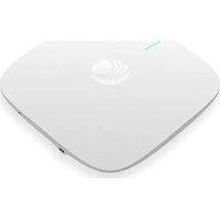
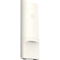

- Cambium Networks™
- Reservation of Rights
- Copyrights
- Restrictions
- License Agreements
- High Risk Materials
- Contents
- Contents 3.
- About This User Guide 7
- Chapter 1: Product Description..10.
- Chapter 2: Basic Settings
- Chapter 3: Advanced Configuration 24
- Chapter 4: Troubleshooting 138
- Appendix: Third Party Software 141
- Cambium Networks 149
- About This User Guide
- Declaration of Conformity
- Part 15 FCC Rules
- Class B Digital Device or Peripheral
- Note
- GNU GPL Information
- Conventions, warnings, Attention, and notes
- Conventions
- Warnings
- Attention
- Notes
- Chapter 1: Product Description
- LED Indicators and interfaces (r190V/r190W/r200/r200P/r195W/r195P)
- LED Indicators and interfaces (r190V/r190W/r200/r200P)
- LED indicators and interfaces (r201/r201P/r201W)
- Hardware installation
- Configuring the router
- Warning
- New in this release
- Web management interface
- EZ UI
- EZ UI Co-branding
- Logging in from the LAN port
- Logging in from the WAN port
- Parental Control
- Accessing and Configuring cnPilot Home Router via cnMaestro
- Managing device via cnMaestro
- Preparing the device
- Performing speed test
- Chapter 3: Advanced Configuration
- Two-Level Management
- Setting the time zone
- Status
- FXS Port Status
- Network Status
- Wireless Info
- System Status
- Configuring the Internet connection
- Custom factory default configuration
- Configuring as Range Extender / Wi-Fi Repeater
- Repeater configuration
- Base AP configuration for repeater mode
- Repeater AP configuration
- Repeater AP LAN IP/WAN IP changes
- Repeater mode best practices
- Network
- WAN
- WAN settings
- Overview
- Change in Port Binding behaviour
- Static IP
- DHCP
- PPPoE
- Bridge mode
- Q-in-Q
- Route mode
- MAC clone
- Fast Bridge setting
- IPv6 address configuration
- Introduction to lpv6
- Enabling IPv6
- Configuring IPv6
- Configuring Statefull IPv6
- Configuring Stateless lpv6
- Viewing WAN port status
- Ipv6 DHCP configuration for LAN/WLAN clients
- LAN DHCPv6
- LAN
- DHCP server
- VPN
- DMZ
- QoS setting
- Routing
- Wireless
- Basic
- Wireless security
- WPS
- Station Info
- Advanced
- WDS
- Bark
- SIP
- SIP Settings
- Parameters and Settings
- Adding one Dial Plan
- Dial Plan Syntactic
- Blacklist
- Call Log
- VoIP QoS
- FXS1
- SIP Account
- Audio Configuration
- Supplementary Service Subscription
- Preferences
- Volume Settings
- Regional
- Features and Call Forward
- Miscellaneous
- FXS2
- Voice calls
- Making a call
- Calling phone or extension numbers
- Direct IP calls
- Call hold
- Blind transfer
- Attended transfer
- Conference
- Security
- Filtering Setting
- Content Filtering
- Application
- UPnP
- IGMP
- Storage
- Disk Management
- Smb Setting
- Administration
- Management
- Administrator settings
- Enabling Mangement access for wireless clients
- Enabling SNMP access over WAN
- Daylight Saving Time
- System Log Setting
- Factory Defaults Setting
- Factory Defaults
- Firmware upgrade
- Provision
- TR-069
- Device Configuration using TR-069
- TR-069 Profile
- Scheduled Tasks
- Diagnosis
- Description
- Ping Test
- Traceroute Test
- Operating Mode
- System Log
- Logout
- Reboot
- Chapter 4: Troubleshooting
- Configuring PC to get IP Address automatically
- Cannot connect to the Web GUI
- Forgotten Password
- cnMaestro On-boarding troubleshooting
- Appendix: Third Party Software
- Appendix: Part Numbers
- Cambium Networks
Brand : Cambium Networks
Model : cnPilot r190
Category : Access Point