PVG-2 - Système d'installation NEP - Free user manual and instructions
Find the device manual for free PVG-2 NEP in PDF.

| Product Type | Installation System / Mounting Bracket |
| Brand | NEP |
| Model | PVG-2 |
| Weight | Approx. 1.5 kg (3.3 lbs) |
| Dimensions (W x H x D) | 300 x 150 x 50 mm (11.8 x 5.9 x 2.0 in) |
| Material | Steel with anti-corrosion coating |
| Maximum Load Capacity | 30 kg (66 lbs) |
| Compatible Screen Sizes | 32" - 65" |
| VESA Compatibility | 75x75, 100x100, 200x200, 300x300, 400x400 mm |
| Mounting Type | Wall-mounted, fixed/ tilt |
| Main Functions | Secure mounting of flat-screen TV or monitor; adjustable tilt angle (0-15°); easy cable management |
| Installation Requirements | Solid concrete or brick wall; M8 expansion bolts included |
| Maintenance | Periodically check screws for tightness; clean with dry cloth |
| Safety Features | Safety lock mechanism to prevent accidental detachment; anti-tip design |
| Spare Parts Availability | Replacement bolts and washers available from NEP service centers |
| Repairability | Modular design allows quick replacement of damaged parts; standard tools required |
| Warranty | 2 years against manufacturing defects |
| Certifications | CE, RoHS, TÜV |
Frequently Asked Questions - PVG-2 NEP
User questions about PVG-2 NEP
0 question about this device. Answer the ones you know or ask your own.
Ask a new question about this device
Download the instructions for your Système d'installation in PDF format for free! Find your manual PVG-2 - NEP and take your electronic device back in hand. On this page are published all the documents necessary for the use of your device. PVG-2 by NEP.
USER MANUAL PVG-2 NEP

NEP RSD System Installation Procedures
Release: March 20, 2022


NORTHERN ELECTRIC

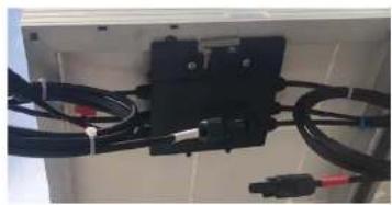
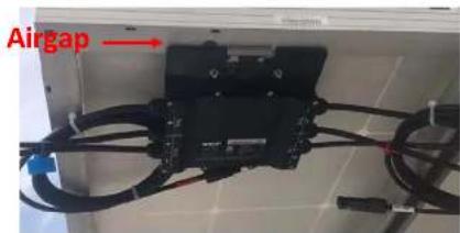
Step-1: Mount PVG
- PVG can be mounted on PV panel frame or on a rail
- Follow module manufacturer's instructions if mounted on frame [Ref: MOUNTING GUIDE PVG]
- A minimum 0.5 inch MUST be kept between any portion of PVG to the backside of a PV panel
- Violation may result in overheat on both PVG and PV panels
- PV cable between PV panels and PVG including extension cable should not be more than 2.0 meters
natural_image
Close-up of black electrical connectors with red and black wires, mounted on a white panel (no visible text or symbols)

natural_image
3D rendering of a black electronic component with four pins, mounted on a blue surface (no text or symbols visible)


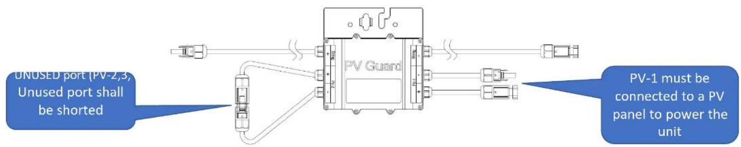
Step-2: Connect PVG to modules
- PVGs must be connected to PV modules before connecting homeruns
- While plugging or unplugging PVGs in a system, DC switch on the inverter must be turned off


Step-3: Test String Output Voltage of PVG
- PVG default state from factory is OFF
- Safety voltages (OFF) when PV-1 port is powered by a PV module
√ PVG_1 and PVG_4: 0.65 Vdc
√PVG_2: 1.4 Vdc
√ PVG_3: 1.8 Vdc

Step-4: Connect Homeruns

- PVGs must be connected to PV modules before connecting homeruns
-
Following steps are recommended* to reduce cross interference between PLC signals from different PVG controllers
-
Separate raceway of homeruns for different PVG controllers as far as possible
- Keep positive and negative conductors of homeruns of the same PV string as close as possible to a twisted pair in a cable tray
- Avoid conductors of homeruns for different PVG controllers in the same raceway
- Separate conductors for different PVG controllers as far as possible


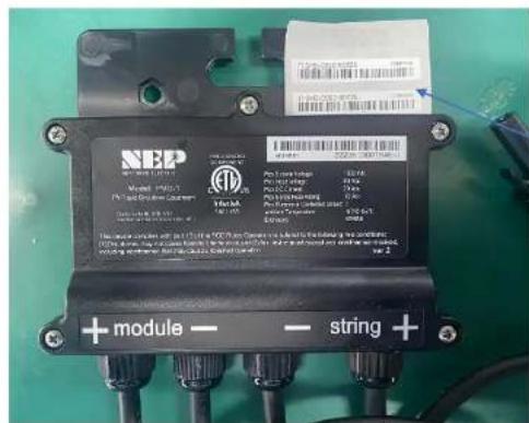
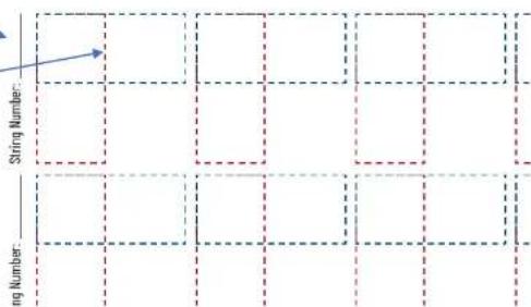
Step-5: Build PVG map
• This step is required for panel level monitoring
• This step is recommended for post installation services

NEP Microinverter/PVG Array Installation I
1 Fill in string number
2 Take one barcode sticker from PVG and put on the map
Job Name:
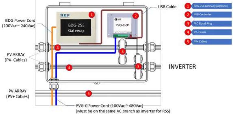
Step-6 and Step-7 are only for external PVG controllers


Step-6\*: Wire PVG Controller Power Supply
• Power conductor to PVG controller shall be 18AWG or 20AWG
- PVG controller shall never loose power supply while inverter is running and taking PV power
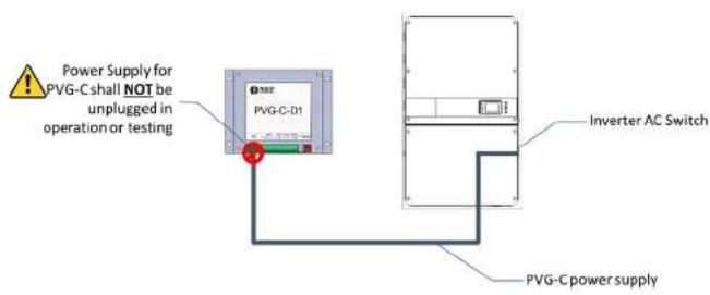
Option 1
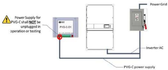
Option 2

Step-6 and Step-7 are only for external PVG controllers


Step-7\*: Connect PVG Controller Signal Ring
- Only positive OR negative PV cables should pass through the signal ring
- PLC signal may cancel each other if both "positive" and "negative" cables pass through the signal rings

NORTHERN ELECTRIC
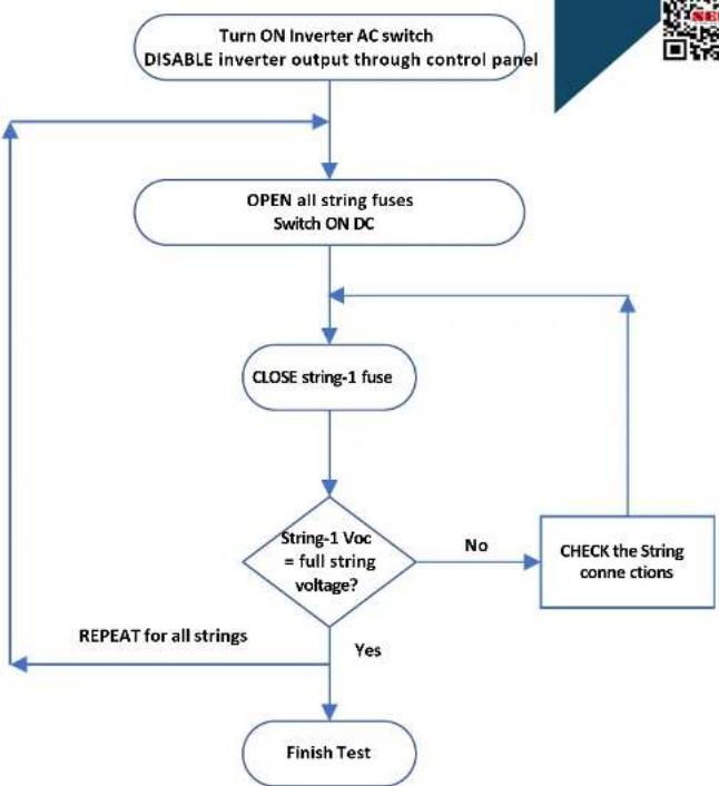
Step-8: Check String Voltage
(Inverter w/ built-in PVG transmitter)
flowchart
graph TD
    A["Turn ON Inverter AC switch\nDISABLE inverter output through control panel"] --> B["OPEN all string fuses\nSwitch ON DC"]
    B --> C["CLOSE string-1 fuse"]
    C --> D{String-1 Voc\n= full string\nvoltage?}
    D -->|No| E["CHECK the String\nconn c tions"]
    D -->|Yes| F["Finish Test"]
    F --> G["REPEAT for all strings"]
    G --> B
northernep.com


natural_image
Abstract geometric logo with red and blue diagonal stripes and a stylized 'N' symbol (no text or symbols present)
Step-9: Commissioning

• After all strings of the site have been tested, inverters can be turned on.
- String current should be checked to confirm on correct operation.

natural_image
Abstract geometric logo with red and blue diagonal stripes and a stylized 'N' symbol (no text or symbols present)
NORTHERN ELECTRIC
Trigger Rapid Shutdown
northernep.com

- Rapid Shutdown should be triggered by pulling the site AC switch that disconnects BOTH inverters AC and PVG power supply
- String voltage should drop to safety voltage within 30 seconds
- NEP RSD System Installation Procedures
- Step-1: Mount PVG
- Step-2: Connect PVG to modules
- Step-3: Test String Output Voltage of PVG
- Step-4: Connect Homeruns
- Step-5: Build PVG map
- Step-6\*: Wire PVG Controller Power Supply
- Step-7\*: Connect PVG Controller Signal Ring
- Step-9: Commissioning
- Trigger Rapid Shutdown
Brand : NEP
Model : PVG-2
Category : Système d'installation