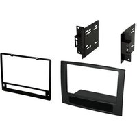
CDK651 - Car Audio Installation Kit PAC - Free user manual and instructions
Find the device manual for free CDK651 PAC in PDF.


| Product Type | Remote Control |
| Brand | PAC |
| Model | CDK651 |
| Dimensions (approx.) | 15.0 x 5.0 x 2.0 cm |
| Weight (approx.) | 100 g (with batteries) |
| Power Source | 2 x AAA batteries (not included) |
| Operating Range | Up to 8 meters |
| Compatible Devices | Various PAC audio/video components |
| Key Functions | Power, volume, channel, input selection, navigation |
| Programming | Pre-programmed for most PAC devices; learn function available |
| Maintenance | Wipe with a soft, dry cloth; avoid liquids |
| Safety | Keep away from water, heat sources, and children under 3 years |
| Spare Parts Available | Batteries, battery compartment cover |
| Repairability | Non-repairable; replace if defective |
| Certifications | CE, RoHS |
| Color | Black |
Frequently Asked Questions - CDK651 PAC
User questions about CDK651 PAC
0 question about this device. Answer the ones you know or ask your own.
Ask a new question about this device
Download the instructions for your Car Audio Installation Kit in PDF format for free! Find your manual CDK651 - PAC and take your electronic device back in hand. On this page are published all the documents necessary for the use of your device. CDK651 by PAC.
USER MANUAL CDK651 PAC
American International
WWW.AIUS.NET
2500 East Francis Street Ontario, CA 91761, U.S.A.
USA Sales (800) 336-6500
CUSTOMER HELP LINE
USA 800-323-4329
iCDK651

American International
Car Stereo Installation Kits & Accessories

natural_image
Technical line drawings of a device casing with cutouts and mounting brackets (no text or symbols)NOTE: Cutting Template
not part of mounting kit.
To be used as a cutting Template ONLY.
VEHICLE APPLICATIONS
Dodge
2006-08 RAM 1500
2006-09 RAM 2500/3500
2010 RAM 2500/3500 Classic Dash
NOTE: THIS INSTALLATION KIT REQUIRES PROFESSIONAL INSTALLATION. THE OEM PANEL WILL NEED TO BE CUT TO MOUNT KIT.
©2015 AMERICAN INTERNATIONAL INDUSTRIES, INC.
TECH Ver. 9/15 PRINT Ver. 9/15
DASH DISASSEMBLY INSTRUCTIONS
AUTOMATIC TRANSMISSION
- Open the lower center console drink holder compartment.
- Remove the (1) 9/32 screw from under each 12 volt power receptacle.
- Carefully starting from the bottom edge, pry the entire Radio/Climate control trim bezel forward to release and lay out of the way.
- Remove the (4) 9/32 screws securing the radio to the sub-dash, pull radio disconnect all harnesses and antenna lead and remove radio.
MANUAL TRANSMISSION
- Carefully lift up and remove the rubber cup holder insert from the lower console bezel.
- Remove the (2) 5/16 screws securing the bottom portion of the cup holder and remove cup holder.
- Remove the (2) 5/16 screws securing the shifter trim and shifter boot, pull towards you and back (sliding rubber boot upward slowly) to allow access to the screws at the of the lower center dash trim panel.
- Remove the (2) 9/32 screws from the lower edge of the bottom center dash trim, depress the trim panel inward and pull down to remove.
- Remove the (1) 9/32 screw from under each 12 volt power receptacle.
- Carefully starting from the bottom edge, pry the entire Radio/Climate control trim bezel forward to release and lay out of the way.
- Remove the (4) 9/32 screws securing the radio to the sub-dash, pull radio forward, disconnect all harnesses and antenna lead and remove radio.
KIT PREPARATION
- Snap the cutting template supplied with the CDK651 to the radio opening of the OEM panel.
- Using the template as a guide cut both the left and right side inside of the template opening, clearing out the OEM panel that would prevent the CDK651 from snapping in.
NOTE: THIS INSTALLATION KIT REQUIRES PROFESSIONAL INSTALLATION. THE OEM PANEL WILL NEED TO BE CUT TO MOUNT KIT.
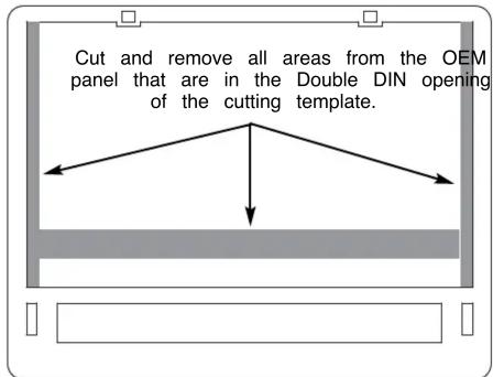
DOUBLE DIN INSTALLATION INSTRUCTIONS
Double DIN Mount Applications
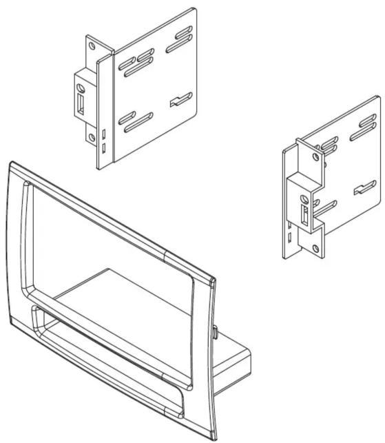
- Insert ISO mountable radio between ISO mount brackets and loosely attach to sides of radio using screws provided with radio when possible, or screws supp with kit. Using the main frame of the CDK651 as a guide, slide radio forward or backward for desired look and then tighten screws to the radio.
NOTE: Attach a rear support bracket to the rear of the new radio and adjust as necessary to support the weight of the radio. Suggested.
natural_image
Technical line drawings of a mechanical housing assembly, showing front, side, and top views (no text or symbols)Brand : PAC
Model : CDK651
Category : Car Audio Installation Kit