GZ 550 DV II - Wood stove JOTUL - Free user manual and instructions
Find the device manual for free GZ 550 DV II JOTUL in PDF.

| Product Type | Wood Stove |
| Brand | Jøtul |
| Model | GZ 550 DV II |
| Fuel Type | Wood logs |
| Heating Capacity | Up to 2,000 sq ft (185 m²) |
| Efficiency | Approx. 80% |
| Height | 32.5 in (826 mm) |
| Width | 22.5 in (572 mm) |
| Depth | 24.5 in (622 mm) |
| Weight | 385 lbs (175 kg) |
| Flue Outlet Diameter | 6 in (152 mm) top or rear |
| Combustion System | Secondary combustion with preheated air |
| Air Controls | Primary and secondary air controls |
| Door Type | Cast iron with ceramic glass |
| Ash Drawer | Removable ash pan |
| Cleaning | Easy-clean glass system; annual chimney cleaning recommended |
| Safety Clearances | Combustible: 36 in (914 mm) from sides, 48 in (1219 mm) from front |
| Emissions | EPA certified, low particulate emissions |
| Warranty | Limited lifetime warranty on cast iron, 5 years on other parts |
| Repairability | Spare parts available; user replaceable door gasket and glass |
Frequently Asked Questions - GZ 550 DV II JOTUL
User questions about GZ 550 DV II JOTUL
0 question about this device. Answer the ones you know or ask your own.
Ask a new question about this device
Download the instructions for your Wood stove in PDF format for free! Find your manual GZ 550 DV II - JOTUL and take your electronic device back in hand. On this page are published all the documents necessary for the use of your device. GZ 550 DV II by JOTUL.
USER MANUAL GZ 550 DV II JOTUL
natural_image
Line drawing of a cabinet with a framed picture on the front panel (no text or symbols)Installation and Operation Instructions
WARNING: If the information in these instructions is not followed exactly, a fire or explosion may result causing property damage, personal injury or death.
- Do not store or use gasoline or other flammable vapors and liquids in the vicinity of this or any other appliance.
-
WHAT TO DO IF YOU SMELL GAS
-
Do not try to light any appliance.
- Do not touch any electrical switch; do not use any phone in your building.
-
Immediately call you gas supplier from a neighbor's phone. Follow the gas supplier's instruction.
• If you cannot reach your gas supplier, call the fire department. -
Installation and service must be performed by a qualified installer, service agency or the gas supplier.
- A carbon monoxide (CO) detector shall be installed in the same rome as the appliance.
Congratulations on the purchase of your new Jotul GZ 550 DV II Acadia Gas Fireplace.
We at Jotul are glad you've made the decision to warm your hearth with a Jotul product. Your new fireplace exemplifies our experience gained over 150 years as the world's largest manufacturer of solid fuel burning appliances. We've been making fine quality cast iron wood and coal stoves and fireplaces continuously since 1853.
The Jøtul GZ550 DV II Acadia fireplace combines advanced gas technology with the warm, traditional elements of cast iron. With proper care and use, your fireplace will provide you with many years of safe, dependable and satisfying service.
The Jøtul GZ550 DV II Acadia is a direct vented gas heater designed and approved for installation into a variety of configurations where close clearance to combustible material is required. Please take a few minutes to familiarize yourself with this manual and the features of your new Jøtul fireplace.
Table of Contents
Specifications 4
Installation / Service Tools...... 5
General Information....5
Safety Information 6
Installation Requirements
Framing 6
Mantel Clearances 8
Hearth Protection 8
Vent Requirements 9
Vertical Termination .... 10
Horizontal Termination ..... 11
Terminal Clearances ..... 11
Vent Restrictor 12
Fireplace Assembly
Blower Installation 12
Gas Connection....14
Gas Pressure 14
High Altitude Adjustment ..... 15
Fuel Conversion....16
Wall Thermostat ....19
Remote Control 19
Antique Brick Kit....20
Log Set Installation 21
Surround Assembly 22
Double Door Installation ..... 22
System Check 23
Operation 25
Maintenance 26
Glass Replacement....26
Service Log 27
Illustrated Parts Breakdown ..... 28
Replacement Parts List 29
Accessories 30
Lighting Instructions .... Back Cover
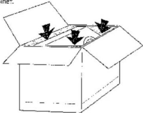
Unpacking the Fireplace
- Before you remove the carton, remove the cast iron parts that are packed around the fireplace cabinet.
natural_image
Simple line drawing of an open box with two arrows pointing downward (no text or symbols)-
Lift the shipping carton off of the fireplace cabinet.
-
Unpack the Firebox. The Logset is packaged inside the firebox. Remove the Glass Panel Frame to unpack the firebox:
- Locate the right and left spring latches on the underside of the firebox floor. Release each latch by pulling them forward to disengage the frame body.
- Pull the Glass Frame away from the firebox and lift to disengage it from the three steel tabs located at the top of the firebox. Set the glass out of the way.
Do not unpack the logs until you are ready to install them.
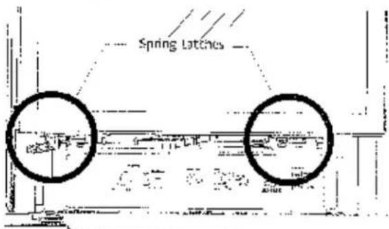
Pull each Spring Latch to disengage them from the Glass Frame.
PLEASE READ THESE INSTRUCTIONS IN THEIR ENTIRETY AND MAKE THEM AVAILABLE TO ANYONE USING OR SERVICING THIS APPLIANCE.
Jøtul GZ 550 DV II Acadia Direct Vent Gas Fireplace
Manufactured and Distributed by:
jøtuf A.S.A.
Fredrikstad, Norway
Jotui North America
Gorham, Maine
M.E.A. No. 369-00-C
Test Standards
This appliance complies with National Safety standards and is tested and listed by Intertek Testing Services of Middleton, Wisconsin Lo ANSI Z21.B8-2002·CSA 2.33-M02 and CAN/CGA 2.17--M91.CSA P.4-01.2 for Canada.

DO NOT ATTEMPT TO ALTER OR MODIFY THE CONSTRUCTION OF THE APPLIANCE OR ITS COMPONENTS. ANY MODIFICATION OR ALTERATION WILL VOID THE WARRANTY, CERTIFICATION AND LISTING OF THIS APPLIANCE.
Specifications
Input Rates
Natural Gas
28,000 OTU/sir. maximum input
16,000 BTU/hr. minimum input
Propane
28,000 BTU/hr. maximum 'rput
15.500 BTU/h, minimum input
Inlet Pressure:
MIN
Natural Gas: 5.0WC (1.24 kPa)
Propane: 12.0 WC (2.98 kPa)
MAX
13.0 W/C (2.74 kPa)
14.9.0 WC (3.72 kPa)
Manifold Pressure: MIN
Nature: Gas: 1.2 WC (29 xPa)
Propane: 2.9 WC (.72 kPa)
MAX
3.8 W/C (94 kPa)
11.0WC (2.74 kPa)
THIS FIREPLACE IS SHIPPED AS A NATURAL GAS FIREPLACE ONLY. IF USE WITH PROPANE IS DESIRED, THE FIREPLACE MUST BE CONVERTED TO USE WITH PROPANE. FOR YOUR CONVENIENCE THIS FIREPLACE IS SHIPPED WITH A PROPANE CONVERSION KIT.
THIS HEATER MUST BE INSTALLED AND MAINTAINED BY A QUALIFIED SERVICE AGENCY.
IN THE COMMENWEALTH OF MASSACHUSETTS, THIS PRODUCT MUST BE INSTALLED BY A LICENSED PLUMBER OR GAS-FITTER.
DO NOT ATTEMPT TO ALTER OR MODIFY THE CONSTRUCTION OF THIS APPLIANCE OR ITS COMPONENTS. ANY MODIFICATION OR ALTERATION WILL VOID THE WARRANTY, CERTIFICATION AND LISTING OF THIS APPLIANCE.
NATIONAL
FIREPLACE
INSTITUTE

CERTIFIED
www.nficertified.org
We recommend that cur gas hearth products be installed and serviced by professionals who are certified in the U.S. by the National Fireplace Institute® (NFi) as NFI Gas Specialists.
General Information
IMPORTANT: SAVE THESE INSTRUCTIONS.
THIS HEATER MUST BE INSTALLED AND MAINTAINED BY A QUALIFIED SERVICE AGENCY.
DO NOT ATTEMPT TO ALTER OR MODIFY THE CONSTRUCTION OF THIS APPLIANCE OR ITS COMPONENTS. ANY MODIFICATION OR ALTERATION WILL VOID THE WARRANTY, CERTIFICATION AND LISTING OF THIS APPLIANCE.
-
The installation and repair of this appliance must be gone by a qualified service person. Failure to properly install and maintain this heater could result in an unsafe or hazardous installation, which may result in a fire, explosion, property damage, personal injury or loss of life.
-
This appliance should be inspected before use and at least annually. More frequent cleaning may be required due to excessive lint from carpeting, bedding material, etc. It is imperative that control compartments, burners and circulating air passageways of the appliance be kept clean.
- The installation must conform to local codes. Your local lotful authorized dealer can assist you in determining what is required in your area for a safe and legal installation. Some areas require a permit to install a gas burning appliance. Always consult your local building inspector or authority having jurisdiction to determine what regulations apply in your area.
In the absence of local codes, the installation requirements must comply with the current National codes. In the U.S., these requirements are established in the National Fuel Code, ANSI Z223.1 (NFPA 54). In Canada, the codes have been established in CAN/CGA B149 Fuel Installation Code.
- DO NOT OPERATE THIS FIREPLACE IF ANY PART
HAS BEEN UNDER WATER.
Immediately call a qualified service technician to inspect the heater and to replace any part of the control system and any gas control which has been under water.
- Do not operate the fireplace with the glass front removed, cracked or broken. Replacement of the glass should be done by a licensed or qualified service person. Only remove glass for routine service. Always handle glass carefully.
-
Notify your insurance company before proceeding with installation of this fireplace.
-
This appliance may be installed in an aftermarket permanently located, manufactured (mobile) home, where not prohibited by local codes. This appliance is only for use with the type(s) of gas indicated on the rating plate. This appliance is not convertible for use with other gases, unless a certified kit is used.
Suggested Tools for Installation and Service
• External regulator (for Propane only)
- Piping which complies with local code
- Manual shuttle valve - T-Handle in MA
- Sediment trap - if required by code
• Commoper end wrench
• 1/2", //16" open end wrench
• Phillips head screwdriver
- Flat head screwdriver - Tee joint
- Pipe wrench - Pipe scalant
- 1/4" nut driver - forx T2C screwdriver
• Gloves • Safety glasses
- Leak test solution - Power Drill
• Reiprocating Saw
Safety Information
Due to the high operating temperatures this appliance should be located out of traffic and away from furniture, draperies, etc. Maintain proper clearance to combustible mantels and fireplace trim.
Children and adults should be alerted to the hazards of high surface temperatures and should stay away to avoid burns or clothing ignition.
■ Young children should be supervised while they are in the same room as the Acadia gas fireplace. Surveiller les enfants. Garder les vetements, les meubles, l'essence ou autres liquides a vapeur inflammables loin de l'appareil.
■ Clothing or other flammable materials should not be placed ON or NEAR the Acadia gas fireplace.
■ Never allow any to use the fireplace if they are unfamiliar with its operation,
■ NEVER store or use gasoline or any other flammable vapors or liquids in the vicinity of the Acadia gas fireplace.
■ Never burn any solid materials (wood, cardboard, paper, coal, etc.) in this gas fireplace. Use with natural gas or propane fuel ONLY.
■ Any safety screen, glass or guard removed for servicing the appliance must be replaced prior to operating the appliance.
■ Do not slam or strike the glass panel.
■ Wear gloves and safety glasses while performing maintenance procedures.
Electrical Hazard
■ Be aware of electrical wiring locations when cutting holes in walls and ceilings for termination.
The optional Acadia Blower (155630) must be electrically grounded in accordance with local codes or, in the absence of local codes, with the current ANSI/NFPA 70, National Electrical Code or CSA C22.1-Canadian Electrical Code.
The Acadia Blower is supplied with a three-prong (grounding) plug for protection against shock hazard and should be plugged directly into a properly grounded three-prong receptacle. DO NOT CUT OR REMOVE THE GROUNDING PRONG FROM THE PLUG.
■ Always disconnect the power supply when performing routine service on the fireplace.
Installation Requirements
The GZ 530 DV Acadia Gas Fireplace and its vent system must be installed within a totally enclosed structure. The fireplace must be connected to the specified vent and termination cap outside the building. Do not vent into another room or inside any part of a building. Under no circumstances may the flow of combustion or ventilation air be obstructed.
The approved vent configurations described herein are derived from extensive testing under controlled laboratory conditions. Gas appliance performance can be negatively affected by variables present in the installation environment, i.e: strong prevailing winds, steep roofs, nearby trees, snow accumulation, etc. These conditions should be taken into consideration by the installer and home owner. In such instances, system performance can often be improved by an increase in the vent height or installation of a high wind termination cap.
Placement and Framing
The combustible framing members of the fireplace enclosure may be placed in direct contact with the fireplace cabinet as specified in the illustrations on the following pages. Use the standof's integrated into the sides and top of the front opening to locate a combustible header and side framing members as shown in the illustrations. See fig. 1.
Electrical Power: If the optional Blower (#155630) will be used, be sure to include provision for a properly grounded, 120 volt house current outlet at the fireplace structure.
Parallel Installation
Although it is possible to place combustible framing members in direct contact with the rear surface of the cabinet, the fireplace must be located forward of the back wall with adequate clearance to accommodate the vent adaptor and subsequent lengths of vent pipe. Consideration must also be given to maintaining a minimum 1 inch (25 mm) clearance between a vertical vent pipe and any combustible materials to the rear of the unit. See Figs. 2, 3, and 4.
Corner Installation
A corner installation will require that the Vent Adaptor be installed in a top exit position. Horizontal terminations will then require use of a 90° elbow. Figs. S and 5a show rear termination with 5/8 Simpson Dura-Vent Wall Thimble #1247.
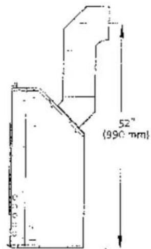
Figure 3. Cabinet Dimensions.
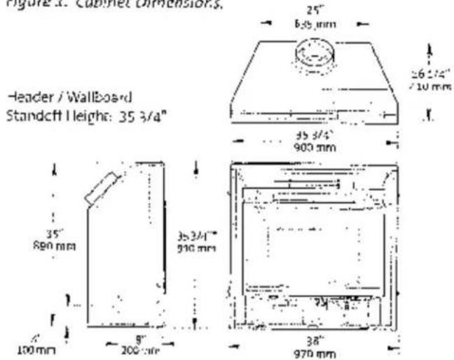
NOTE: DO NOT INSTALL CABINET ON FLOOR SURFACE LOWER THAN THE FRONTAL HEARTH SURFACE.
Horizontal Vent: Minimum depth accommodates the length of Vent Adaptor and one 6' ver-1 section through wall construction.
$$ \begin{array}{c c} \text {Vent Adaptor:} & 5 / 8 \ A = & 2 1 3 / 4 ^ {\prime \prime} \end{array} $$
Vertical Vent: Minimum depth includes 1 inch clearance between Vent Adaptor and combustible wall construction.
$$ \begin{array}{c c c} \text {Vont Adaptor:} & 5 / 8 & 4 / 6 \ A = & 2 1 1 / 2 ^ {\circ} & 2 0 ^ {\circ} \end{array} $$
Figure 3. Depth requirement to rear wall.
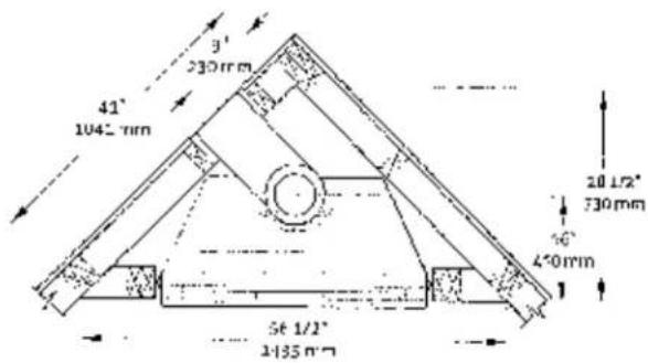
Figure 5. Corner framing dimensions.
Figure 2. Minimum horizontal vent allowance through wall.
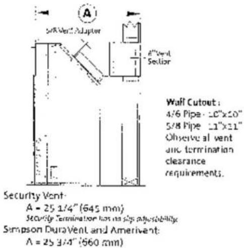
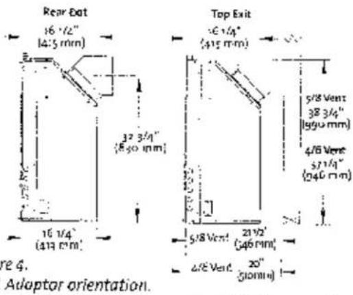
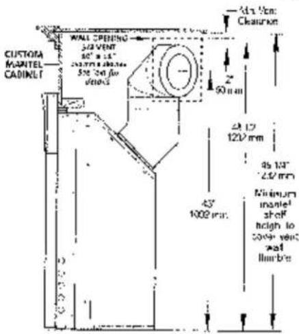
Figure 5a. Corner Installation - 5/8 vent, rear termination.
Hearth Protection
The G2550 DV-II Acadia is approved for installation without hearth protection. Combustible materials may be used on the floor directly under and in front of the fireplace. NOTE: The floor surface under the unit must be level with, or higher than, the surface in front of the unit to allow the fireplace Controls Door to fully open.
Facing and Clearance Requirements
The following clearance and hearth specifications are the minimum requirements for the G7550 DV II Acadia gas fireplace. Measure clearances from the steel fireplace cabinet - not the cast iron surround panels. See Figures 6 - 8.
A combustible surface is anything that can burn (i.e. sheet rock, wallpaper, wood, fabrics etc.). These surfaces are not limited to those that are visible and also include materials that are behind non-rombustibles.
If you are not sure of the combustible nature of a material, consult your local fire officials. "Fire Resistant" materials are considered combustible - they are difficult to ignite, but will burn. "Fire-rated" sheet rock is also considered combustible.
Maintain the proper clearances to the appliance to allow adequate flow of ventilation air around the fireplace.
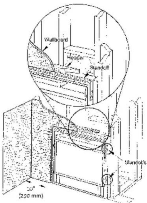
Figure 6. Header and Side Standoffs
Mantel and Trim Clearance
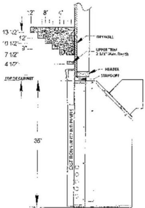
Figure 7. Minimum Mantel Clearances. Measure clearances from the top of the fireplace cabinet before installation of the cast iron surround panels.
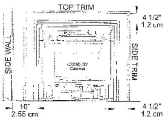
Figure 8. Minimum Wall and Trim Clearance. Measured from the cabinet, not standoffs or cast iron panels. Maximum Top & Side Trim depth: 2 1/2" (64 mm)
Vent Requirements
The GZ550 DV II Acadia Gas Fireplace is approved for use with direct vent components produced by the following manufacturers:
• Simpson Dura-Vent Corporation, 5/8 and 4/6 pipe
• Security Vent Ltd. International, 5/8 and 4/6 pipe
• Amerivenl Corporation, 4/5 pipe
• Selkirk Metalbestos Corp. MDV Direct Vent Systems
Use vent components from a single vent manufacturer. Do not combine parts from different manufacturers in a single installation.
The vent termination must fall within the shaded area designated in the diagrams in Figures 12 - 14.
Venting Guidelines
The minimum height for a vertical termination cap must be no less than 7' from the top of the unit. The maximum height must not exceed 35'.
The minimum vent height above the roof or adjacent walls is specified by major building codes. Use the Gas Vent Rule as a general guide. See fig 10. requirements of the approval listing and the manufacturer's instructions.
Clearance (airspace) between Vent and Combustibles: Top - 2" (51 mm) Sides/Bottom - 1" (25 mm)
■ Wall Cutout Dimensions: 4/6 Pipe - 10" x 10" 5/8 Pipe - 11" x 11"
■ Any horizontal run must rise 1/4" per foot.
■ Install venting in accordance with the vent manufacturers' instructions. Never modify any venting component, or use any damaged venting product.
■ THE GAS APPLIANCE AND VENT SYSTEM MUST BE VENTED DIRECTLY TO THE OUTSIDE OF THE BUILDING. DO NOT CONNECT VENT TO A CHIMNEY SERVING A SOLID FUEL OR ANOTHER GAS APPLIANCE.
Joint Sealing Requirement: Apply a 1/8" bead of high-temperature (750°F) sealant to the male section of the inner vent pipe. See fig. 9. The cement should seal the inner pipe from the outer pipe.
Figure 9. Seal each inner joint before joining pipe.
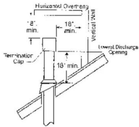
Figure 10. Gas Vent Height Rule: Vertical vent termination height above roof.
■ Do not recess the vent terminal into a wall or siding.
■ Inspect the vent system annually for blockage and deterioration. If the vent-air intake system is disassembled for any reason, reinstall according to the instructions provided for initial installation.
■ Installation of any components not manufactured or approved by Jputul or failure to meet all clearance requirements will void all warranties and may result in property damage, bodily injury, or loss of life.
IN DESIGNING THE VENT SYSTEM, DO NOT COUNT THE 45° ELBOW CONNECTED TO THE VENT COLLAR AS AN ELBOW.
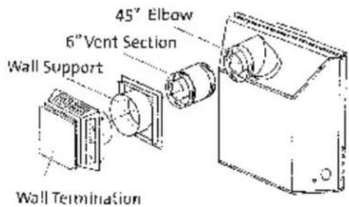
Figure 2.1. Typical minimum horizontal vent configuration - 5/8 Simpson DuraVent. Do not use 4/6 pipe in this configuration.
line
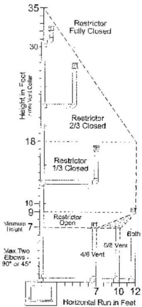
| Horizontal Run in Feet | Height in Feet | | ---------------------- | -------------- | | 7 | 35 | | 10 | 30 | | 12 | 18 | | 7 | 10 | | 10 | 9 | | 12 | 7 | | 7 | 4/6 Vent | | 10 | 5/8 Vent | | 12 | Both |Figure 12. Vent Window for vertical termination using 5/8 or 4/6 pipe.
Vertical Termination
The vent must terminate within the shaded area designated on the graphs in figs. 12 and 13.
• Maximum Elbows - Two 90" or Two 45" (Do not count the first elbow off the vent collar.)
- Use the restrictor settings indicated in the graph as general guide. The specific characteristics of your installation may require different settings.
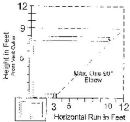
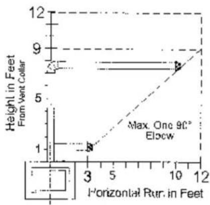
Horizontal Termination
The vent must terminate within the shaded area designated in Figs. 15 and 16. (Do not count the first elbow off the vent collar.)
• Max Elbows - One 90" or one 45".
• Use of 4/6 pipe requires a minimum 1 foot rise. Fig. 16.
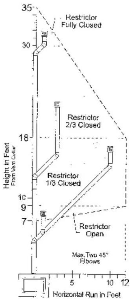
Figure 23. Vent Window for offset vertical termination using 5/8 or 4/6 pipe.
Figure 14. Minimum centerline for horizontal termination cf 4/6 pipe
line
| Horizontal Run in Feet | Height in Feet From Vent Cubes | | ---------------------- | ------------------------------- | | 3 | 1 | | 5 | 5 | | 10 | 9 | | 12 | 12 |Figure 15. Horizontal termination -5/8 pipe.
line
| Horizontal Run. in Feet | Height in Feet From Vent Collar | | ----------------------- | -------------------------------- | | 3 | 1 | | 10 | 9 |Figure 16. Horizontal Termination - 4/6 Pipe. Minimum 1 ft rise required.
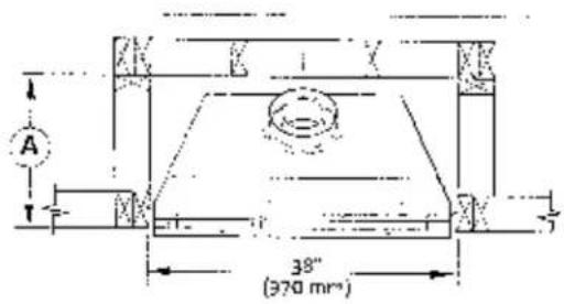
Horizontal Termination Clearance

Figure 17. Vent Terminal Clearances.
A - Clearance above grade, veranda, porch, deck, or balcony: 12 inches (30 cm) minimum.
B = Clearance to window or door that may be opened.
*Min. 9 inches, U.S. / *12 inches (30 cm) CAN.
We recommend 12in, minimum to prevent condensation or the window.
C - Clearance to permanently closed window:
**Min. 9 inches, U.S. / *12 inches (30 cm) CAN
We recommend 12 in. minimum to prevent condensation on the window.
D = Vertical clearance to ventilated soffit located above the terminal within a horizontal distance of 2 feet (60 cm) from the centerline of the terminal; 18 inches (46 cm) minimum.
E = Clearance to unventilated soffit: 12 inches (30 cm) minimum.
F. Clearance to outside corner: **Min. 9 inches, U.S. / *12 inches (30 cm) CAN. We strongly recommended 12 inches, particularly where windy conditions prevail.
* In accordance with CSA B149 Installation Codes.
** In accordance with the current ANSI Z223.1/NEPPA 54, National Fuel Gas Code. Note: Local Codes and Regulations may require different clearances.
G = Clearance to inside corner; ** Min. 6 inches, U.S. / *12
inches (30 cm) CAN. We strongly recommend 12 inches, particularly where windy conditions prevail.
H = "Not to be installed within 15 feet (4.5 m) above a meter/regulator assembly within 3 feet (90 cm) horizontally from the center-line of the regulator.
I = Clearance to service regulator vent outlet: 3 feet (91 cm) minimum.
J = Clearance to nonmechanical air supply inlet to building or the combustion air inlet to any other appliance: 12 inches (30 cm) minimum.
K = Clearance to a mechanical air supply inlet:
**Min. 3 feet (91 cm) above if within 10 feet horizontally, U.S. / *6 feet (1.83 m) minimum / CAN
L = 3 Clearance above paved sidewalk or a paved driveway located on public property: 7 feet (2.1 m) min.
M - Clearance under veranda, porch, deck, or balcony: 12 inches (30 cm) minimum. ^2
A vent shall not terminate directly above a sidewalk or driveway which is located between two single family dwellings and serves both dwellings.
2. Only permitted if veranda, porch, deck, or balcony, is fully open on a minimum of two sides beneath the floor.*
Variable Vent Restriction
Vent restriction is accomplished by sliding a restrictor panel over the combustion air intake parts. Located at the back of the firebox. See Fig 19. The panel is set in a fully open position at the factory. Use the Vent Window diagrams in Figs. 12-13 as a starting point to determine the best restriction setting. Follow these steps to adjust the restriction as necessary:
- Remove the Controls Panel to access the adjustment lever at the rear of the valve compartment. Simply loosen the two wings but that secure the panel to the cabinet floor and pull the panel forward. You do not need to disconnect any wires.
- Locale the vent restriction wingnut protruding from the firebox floor at the rear of the valve compartment. Loosen the wingnut and push the lever to the left to increase restriction in one inch increments, e.g: 1 inch travel . 1/3 closed position.
The ideal restrictor setting for a particular vent system will vary depending on the specific installation characteristics. Once the fireplace is operating, further restrictor adjustment may be necessary to obtain the best performance. See the Operation chapter of this manual for more information.
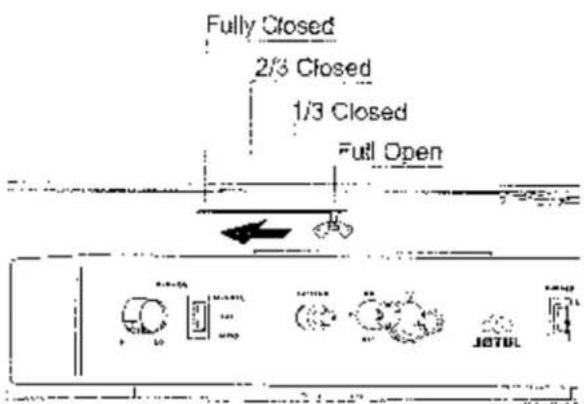
Figure 19. Vent restrictor adjustment.
Fireplace Installation
Optional Blower
Install the optional Blower (155630) before installing the gas supply line.
Power Requirement
The blower must be electrical y grounded in accordance with local codes or, in the absence of local codes, with the current NFPA 70- National Electrical Code or CSA C22.1-Canadian Code.
A three-prong (grounding) power supply plug is included for protection against shock hazard and should be plugged directly into a properly grounded three-prong receptacle. DO NOT CUT OR REMOVE THE GROUNDING PRONG FROM THE PLUG.
Blower Function
In the Auto mode, the blower is controlled by a heat activated switch (snapstat) that will turn the fan on and off as the firebox heats and cools. Use the Manual mode to over-ride the snapstat. If the blower is not needed, place the blower control switch in the OFF position and the snapstat will not function.
CAUTION: Always unplug the Blower when performing any routine service to the Acadia gas fireplace.
Installation
- Loosen the two wingnuts that secure the Control Panel to the fireplace floor. Pull the panel forward and swing it to the right to access the rear of the cabinet. Do not disconnect any wires.
- Insert a rubber grommet at each corner of the Base Plate as shown in Fig. 20.
- Engage the Blower unit base with the four studs at the rear of the fireplace cabinet floor. See Fig. 21.
- Insert the Snapstat into the slot in the Snapslat Bracket and, using the M6 nuts and 10 mm socket, attach the Control Switch / Snapslat Bracket to the two studs procuding from the firebox floor. See fig. 22.
- Connect the Blower Wire harness to the switch connector at the back of the Control Panel. Connect the two other leads to either terminal on the snapstar. Attach the green ground wire to the left Control Panel mounting stud. Replace the Control Panel and tighten the wingnuts.
- Run the power cord to the duplex receptacle in the side of the cabinet. Gather slack cord into the side cavity, away from the plumbing and other wiring.
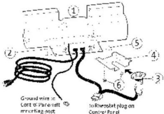
-
129374 Fan/Motor Unit 5 #20055 Crummets, 4
-
220012 Base P ale
-
9930 Mb Hex Nuts, 2
-
22063; Snapshot (140°F - 120°F)
-
220989 Snapstat Bracket
Figure 20. Blower Kit 155630 contents.
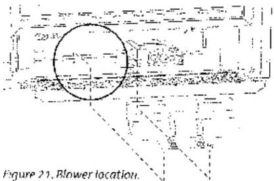
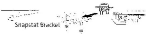
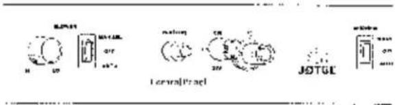
Figure 22. Install snapstat bracket and switch box.
natural_image
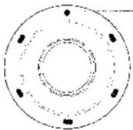
Pure concentric circular diagram with no text, numbers, or symbolsFor correct vent pipe alignment, be sure the round hole is oriented to the 12 o'clock posit or
Figure 23. 4/6 Vent Lollar orientation.
Final Cabinet Positioning
- If appropriate, attach the 4/6 Vent Adaptor Collar:
- Remove the 5/8 Collar supplied with the unit.
- Align the 4/6 Collar as shown in fig. 23 and secure to the unit using the original screws. Be sure the single round fastener hole is oriented to the 12 o-clock position for proper vent alignment.
- Side Standoffs: Remove the retainer screws. Using vise grips or pliers, fold each standoff at the perforations. Secure each standoff using the screws previously removed. See fig. 24.
- Wall Stud Brace: Loosen, bend, and position each cabinet Retainer Strap for attachment to the fireplace enclosure. See fig. 24.
- Locate the fireplace cabinet in its final position within the enclosure. Confirm that the first 45° Elbow is correctly aligned for final vent assembly and secure it to the Vent Collar using 3. #10 sheet metal screws.
- Confirm that the cabinet is positioned to align its forward edge with the finished surface of the wall facing. The stud braces allow approximately 2 inches of forward adjustment to accommodate most any facing thickness. Secure the braces to the enclosure frame.
- Complete the gas line and electrical power routing as appropriate for blower and thermostat functions.
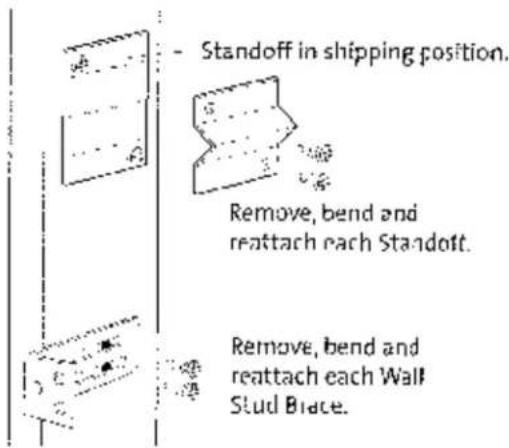
Figure 24. Standoff and Stud Brace orientation.
Connect the Gas Supply
Gas Supply Requirements
ALL INSTALLATIONS MUST COMPLY WITH LOCAL CODE OR IN THE ASSENCE OF LOCAL CODE, MUST COMPLY WITH THE MOST RECENT EDITION OF THE NATIONAL FUEL GAS CODE ANSI: Z223.1/NFPA 54 OR CAN-B149.
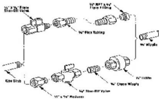
Shutoff Valve
All codes require a gas shutoff valve (gas cock) and union to be installed in the supply line and in the same room as the appliance. This allows for the disconnection of the fireplace for servicing and maintenance. See fig. 25.
A T-handle gas shutoff valve is required in Massachusetts in compliance with Code 248CMR.
The fireplace and gas control valve must be disconnected from the gas supply piping during any pressure testing of the system at test pressures in excess of 1/2 psig. For pressures lower than 1/2 psig, isolate the gas supply by closing the manual shuloff valve.
Control Valve Connection
The gas supply line connection is made to the left side of the valve. The gas supply line should be a minimum 3/8" diameter, or the appropriate size to provide sufficient gas pressure to the valve regardless of the input setting.
The use of flexible gas appliance connectors is acceptable in many areas in the U.S. In Canada, methods vary depending on local code. If local codes permit, use flexible gas line for ease of installation and service. For those locales where flexible gas lines are not permitted, use the 3/8" iron fitting to make the connection at the left side of the Control Valve. See Figures 25 and 26.
Secure all joints tightly using appropriate tools and sealing compounds (for propane units, be sure to use compounds that are propane resistant). Turn on gas supply and test for gas leaks using a soapy water solution. Never use an open flame to check for leaks.
Leak test:
• Mix a 50-50 solution of water and dish soap.
- Light appliance- see lighting instructions on page 23 of this manual or on the fireplace's rating plate.
- Brush or spray all joints and connections with the soapy water solution.
- If bubbles appear at any connection or seam or a gas odor is detected, immediately turn gas control knob to the OFF position.
Tighter or reconnect the leaking joint and retest for any gas leaks.
flowchart
graph TD
    A["34° Flex Tube"] --> B["95° MIPole"]
    A --> C["95° A 75° Reducer"]
    D["Gas Sub"] --> A
    E["34° MIPole"] --> F["95° MIPole"]
    G["95° A 75° Reducer"] --> H["95° MIPole"]
    I["Shown-Bill System"] --> J["95° MIPole"]
    K["Chassis Mipole"] --> L["95° MIPole"]
Figure 25. Gas supply line fittings.
Gas Pressure
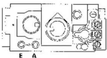
Proper gas pressure provides a consistent flow of gas to the appliance and is instrumental in checking for gas leaks. The gas control valve on the fireplace is equipped with pressure test points for gauge connections. The gauge connections are located on the front of the valve under the On/Off/Pilot knob. Gauge connections are identified by:
- IN/E for inlet or supply pressure (the amount of gas coming to the valve.)
- OUT/A for manifold pressure (the amount of gas that is coming out of the valve to the burner.)
natural_image
Pure electrical circuit lines without any symbolsFigure 26. Pressure test point as located on the front of the valve.
The appliance must be isolated from the gas supply line by closing its individual manual gas shutoff valve (gas cock) during any pressure testing of the gas supply piping system that is equal to or less than pressures of 1/2 psig (3.5 kPa).
Inlet Pressure
| MIN | MAX | |
| Natural Gas: 5.0 WC (1.24 kPa) | 11.0 WC (2.74 kPa) | |
| Propane: 12.0 WC (2.98 kPa) | 14.9 WC (3.71kPa) | |
Manifold Pressure
| MIN | MAX | |
| Natural Gas: 1.2 WC (.29 kPa) | 3.8 WC (.94 kPa) | |
| Propane: 2.9 WC (.72 kPa) | 11.0 WC (2.74 kPa) | |
ALWAYS TEST PRESSURE WITH VALVE CONTROL KNOB SET ON HIGH. Symptoms of incorrect gas pressure include:
Insufficient gas pressure:
- Small pilor: flame which can result in insufficient millivolts.
- Little variation in flame picture between HI and IO settings.
- Insufficient gas to support more than one appliance causing nuisance outages or gas surges.
Excessive gas pressure:
• Permanent damage to valve causing complete appliance shut down.
- Too large a pilot flame resulting in overheating of the power generator and consequent shut down.
- Sooting due to impingement and/or incorrect fuel to air mix.
High Altitude Adjustment
Installations located at altitudes from 2000 - 4500 L (610 M - 1370 M), require compensation for the thinner air (less volume of air per cubic foot). Higher altitudes affect the atmospheric pressure and heat value of gaseous fuels. The lower oxygen content in the air and the lower gas viscosity require the use of a different orifice to achieve efficient, clean combustion at the burner tube.
For high altitude installations consult the local gas distributor or the authority having jurisdiction for proper rating methods. If the installer must convert the unit to adjust for varying altitudes, use f#tul High Altitude Kit (#155610-NG / #155611-LP).
In the U.S: THE DERATING KIT MUST BE INSTALLED BY AN AUTHORIZED SERVICE TECHNICIAN IN ACCOR-
DANCE WITH THE MANUFACTURER'S INSTRUCTIONS AND ALL CODES AND REQUIREMENTS OF THE AUTHORITY HAVING JURISDICTION. THE INFORMATION STICKER MUST BE COMPLETED BY THE INSTALLER AND APPLIED TO THE APPLIANCE AT THE TIME OF THE CONVERSION. THE QUALIFIED SERVICE AGENCY PERFORMING THIS WORK ASSUMES RESPONSIBILITY FOR THIS DERATING.
In Canada: this unit has been tested for installation at high altitudes in accordance with Canadian test standard CAN/CGA 2.17. THE DERATING SHALL BE CARRIED OUT IN ACCORDANCE WITH THE REQUIREMENTS OF THE PROVINCIAL AUTHORITIES HAVING IURISDICTION AND IN ACCORDANCE WITH THE REQUIREMENTS OF THE CAN1-B-149.1 AND .2 INSTALLATION CODE.
Derating Procedure
- Follow Steps 1-4 of the Fuel Conversion procedure outlined on page 14.
- Remove the original orifice. Consult Table 1 to determine the correct orifice size for your elevation and fuel type. Install the appropriate orifice included in the high altitude kit.
- Fill out the high altitude conversion label and attach to the rating plate or fireplace cabinet floor See Figure 27.
4 Reassemble the firebox components. - It may be necessary to adjust the air shutter on the burner tube. See the AIR SHUTTER/FLAME APPEARANCE section of this manual for more details.
| High Altitude Orifice Chart | |||
| Elevation | Fuel | Orifice Size | Part No. |
| 0 - 2000 ft.(0 - 610 m) | Natural GasPropane | 4381.55 mm | 129130120048 |
| 2001 - 4500 ft.(611 - 1370 m) | Natural GasPropane | 3391.50 mm | 129367129146 |
Table 1. High Altitude Orifice Chart.
| THIS STOVE HAS BEEN CONVERTED FOR USE AT AN ALTITUDE OF: _ | |
| Orifice Size: _ Manifold Press. _ | |
| Input Btu/Hr. _ Fuel Type _ | |
| Date of Conversion _ |
Figure 27. High Altitude Conversion Label.
Fuel Conversion
The G7550 DV Acadia Fireplace is designed to for use with either Natural gas or Propane. It is shipped from the factory configured to use Natural gas. A conversion kit is included for conversion to Propane use it desired. Check the identification label on the Control Valve to confirm that the correct fuel is used.
WARNING:
THE CONVERSION KIT IS TO BE INSTALLED BY AN AUTHORIZED J∅TUL SERVICE TECHNICIAN IN ACCORDANCE WITH THE MANUFACTURER'S INSTRUCTION AND ALL CODES AND REQUIREMENTS OF THE AUTHORITY HAVING JURISDICTION. FAILURE TO FOLLOW THESE INSTRUCTIONS COULD RESULT IN SERIOUS INJURY OR PROPERTY DAMAGE. THE QUALIFIED AGENCY PERFORMING THIS WORK ASSUMES RESPONSIBILITY FOR THIS CONVERSION.
IN CANADA:
THE CONVERSION SHALL BE CARRIED OUT IN ACCORDANCE WITH THE REQUIREMENTS OF THE PROVINCIAL AUTHORITIES HAVING JURISDICTION AND IN ACCORDANCE WITH THE REQUIREMENTS OF THE CAN1-B149.1 AND .2 INSTALLATION CODE.
1/4" Nut driver, 7/16" and 1/2" open end wrench or deep well socket, 4 mm alien wrench, Torx 120 or slotted screwdriver.
Conversion Kit Contents:
• 1. Regulator Tower labeled for Propane
• 3 Regulator Tower Screws
• 1 Burner Office (#38 NG, 1.55 mm. LP)
• 1 Pilot Orifice (#30 for LP, #51 for NC)
- Label A - to be completed and applied to the back of the fireplace.
- Label B - apply to the fireplace Rating Plate as designated on the plate.
WARNING: If appropriate, be sure to unplug the blower before proceeding with this conversion.
Fuel Conversion Procedure
1. Remove the Glass Frame:
• Follow the removal procedure detailed on page 1.
2. Empty the firebox:
- Lift and remove the Fettle and Logset package. CAUTION: THE LOGS ARE FRAGILE. Handle them with care and set aside out of the way.
- Remove the Burner Skirt. Lift and tilt it to clear the firebox opening. See fig. 28.
3. Change the Burner Orifice:
- Loosen the locknut on the Air Shutter Stem, located under the firebox floor to the right of the Control Valve. Pull the stem forward as far as it will go. This will allow you to disengage the Burner Assembly. See fig. 29.
- Lift the rear of the Burner Tube and rotate slightly forward. Slide the tube back enough to disengage it from the Air Shutter and Burrer Orifice, then lift out. See fig. 30.
- Slide the Air Shutter back out of the way to expose the orifice. See fig. 31. Using a 12 " open end wrench or deep well socket: remove the burner orifice and replace with the appropriate orifice, supplied in the kit.
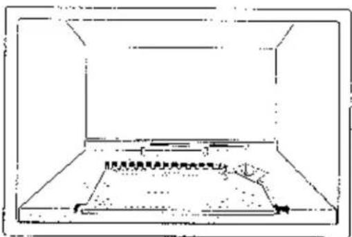
Figure 28. Lift the Burner Skirt up and out of the firebox.
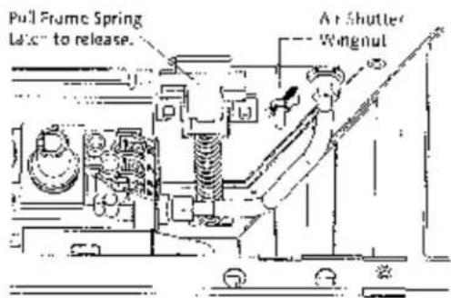
Figure 29. Frame latch and air shutter stem location.
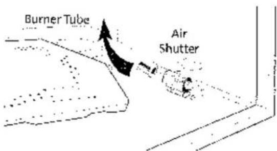
Figure 30. Move shutter forward to disengage the burner tube assembly.
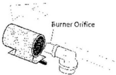
Figure 31. Move air shutter back to access the burner orifice.
4. Change the Pilot Orifice:
- FROM WITHIN THE FIREBOX disengage the Pilot Hood by releasing the retainer clip as shown in fig. 32. Using the 4 min hex key supplied, unscrew the pilot orifice (counter-clockwise). Replace with the appropriate orifice;
51 for Natural gas
30 for Propane
Tighten new orifice into the base of the pilot assembly.
- Replace Pilot Hood by pushing it into the base.
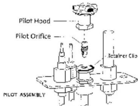
Figure 32. Pilot Orifice replacement.
- Replace the Burner Tube: Slip the end of the tube into the Air Shutter and SLIDE TUBE FORWARD TO COMPLETELY COVER THE BURNER ORIFICE.
-
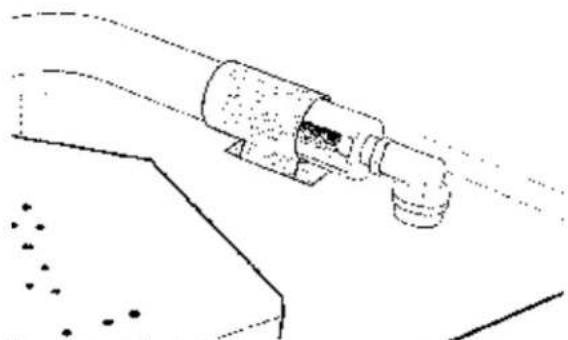
Adjust the Air Shutter: See fig. 33.
-
Slide the shutter BACK to open the inlet, slide FORWARD to close. The standard settings are: Natural gas - 1/4" open Propane - 1/2" open
• Tighten the wing nut on the Air Shutter Stem. -
Replace the Burner Skirt.
-
Change the Regulator: See fig. 34.
-
Using a Torx T-20 screwdriver or small flat head screwdriver, remove the three specialty screws from the front of the valve regulator.
-
Remove the regulator tower and gasket. BE SURE TO REMOVE THE BLACK RUBBER GASKET FROM THE VALVE.
• Install the new variable regulator lower with the new rubber gasket. Thoroughly tighten new regulator to valve body. -
Apply the Conversion Labels:
-
Apply LABEL A to the cabinet floor so that is may be seen by anyone servicing the fireplace.
-
Apply LABEL B to the Rating Plate in the space provided.
-
Reassemble the fireplace, apply gas to the system and check for gas leaks including all gas lines before and after the valve. NEVER USE AN OPEN FLAME TO CHECK FOR GAS LEAKS.
IMPORTANT: Correct gas pressure is essential for efficient and safe operation. It is important that the correct gas pressure be established at the time of the installation. For more details, see the Gas Pressure section of this manual on page 12.
WHEN LIGHTING THIS APPLIANCE, ALWAYS REFER TO THE LIGHTING INSTRUCTIONS ON THE BACK COVER OF THIS MANUAL.
natural_image
Technical line drawing of a mechanical component with no visible text or symbolsFigure 33. Adjust Air Shutter as appropriate. Fully open position is shown here. Slide shutter forward to close.

Figure 34. Valve Regulator replacement.
Wall Thermostat Installation
Use Jøtul Thermostat #129706 or a 750 millivolt DC two-wire circuit thermostat to automatically control your fireplace operation. The thermostat should be placed in the same room as the heater, typically 5' off the floor. Avoid drafty areas or any area that may affect the accuracy of the thermostat.
The thermostat should be connected to the Acadia using a minimum of 16 gauge wire with a maximum length of 35 feet of wire.
Connect the two thermostat wire leads to the two lower terminals on the terminal block located to the right of the ON/OFF/T'STAT switch. Do not overtighten the connections. IT IS NOT NECESSARY TO DISCONNECT ANY OTHER WIRES. See Figure 34.
At the thermostat, the two wires should be connected to the two connections screw on the thermostat base plate per the manufacturer's instructions.
For thermostatic function, place the ON/OFF/T STAT switch in the T-STAT position and the pilot flame must be lit.
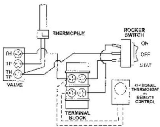
flowchart
graph TD
    A["Valve"] --> B["TH TIP"]
    B --> C["THERMOPILE"]
    C --> D["TERMINAL BLOCK"]
    D --> E["ROCKER SWITCH ON OFF STAT"]
    E --> F["OPTIONAL THERMOSTAT REMOTE CONTROL"]
Figure 36. ZG550 Acadia Wiring Diagram
Remote Control
The optional Iotul Remote Control can be installed on the Acadia gas fireplace. Using the wire supplied with the remote, connect the remote directly to the gas control valve. See fig. 36
Connect one receiver lead to the terminal labeled TH. Connect the other receiver lead to the terminal labeled TH/TP. DO NOT DISCONNECT ANY OTHER WIRES FROM THE VALVE, AND DO NOT OVER TIGHTEN THE TERMINAL SCREWS.
Place the receiver unit under the control valve on the floor of the fireplace cabinet.
CAUTION:
LABEL ALL WIRES PRIOR TO DISCONNECTION WHEN SERVICING THE CONTROLS. WIRING ERRORS CAN CAUSE IMPROPER AND DANGEROUS OPERATION. ALWAYS VERIFY PROPER OPERATION AFTER SERVICING THE APPLIANCE.
ATTENTION:
AU MOMENT DE L'ENTRETIENDES COMMANDES, ETIQUETEZ TOUS LES FILS AVANT LE DEBRANCHEMENT. DES ERREURS DE CABLAGE PEUVENT ENTRAIUN FONCTIONNEMENT INADEQUAT ET DAGEREUX.
Brick Panel Assembly
Instal the optional 155805 Brick Panels before placing the Logset. Place the panels in position in the order as numbered in fig. 37. No fasteners or tools are required.
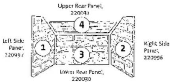
Figure 37. Panel installation: order.
- Remove the Glass Frame, if you have not already done so. Open the lower control panel and locate the two frame latches under the firebox floor. See fig. 38. Pull the latch handle forward to disengage it from the bottom of the glass frame. You can then pull the frame out and up off of the three retainer tabs at the top of the firebox opening. Set the Glass Frame out of the way.
- Remove the Fettle and Logset. These parts are not fastened. Simply lift them out of the firebox.
- Install the Side Panels. Set the bottom edge of each side panel on the Burner Skirt and against the firebox wall. Push the panel forward against the front line of the firebox opening. See fig. 39.
- Install the Lower Rear Panel. Orient the panel so that the beveled edge is on top and the mortar joints align with those on the side panels. Set the bottom edge on the shelf above the restrictor adjustment slots at the back of the firebox. The panel should fit snugly between the two side panels. See fig. 40.
- Install the Upper Rear Panel. This will also be a snug fit. Set the panel up high and then carefully lower it to seat its lower edge against the top of the other rear panel. The side panels will hold it in place.
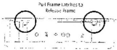
Figure 38. Glass Frame latch locations.
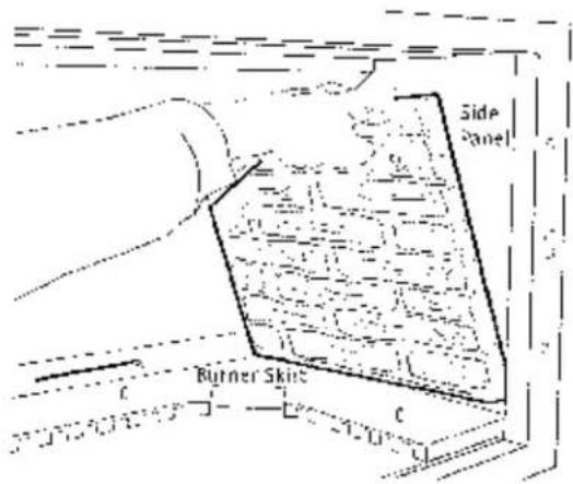
Figure 39. Install the Side Panels.
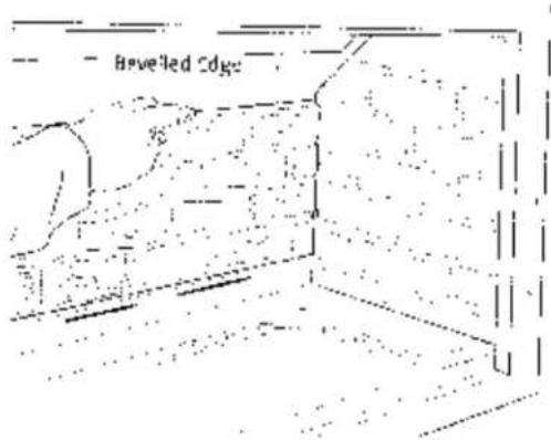
Figure 40. Install Lower Rear Panel.
Logset Assembly
Unpack and arrange the five logs as outlined below. CAUTION: The logs are fragile. Handle with care.
-
Seat Right Log (1) on the pan on the right side of the Burner Skirt. Fig. 41.
-
Set Rear Log (2) on the pins at the rear of the Burner Skirt. This log should overlap the back of the Right Log.
-
Set the Left Lug (3) on the pins at the left side of the Burner Skirt.
-
Set the end of Front Log (4) into the pocket at the rear of Left Log (3). Engage the other end with the pin in the middle of the Burner Plate. Fig. 42.
-
Engage the upper end of the Cross-over Log (5) with the pin in the Rear Log. Fig. 42. Set the Cross-over Log across the top of the lower end of the Front Log (4) as illustrated.
-
Spread a layer of ember stones evenly over the surface of the Burner Plate. Allow for 1/4" clearance between the stones and the inner edge of the Burner Skirt. Avoid blocking the pilot flame area with ember stones. See Fig. 43.
-
Replace the Glass Panel Frame: Engage the top of the frame with the three tabs at the top of the firebox. Push the bottom of the frame against the firebox face and pull the Frame Latches out to engage them with the slots in the bottom of the frame.
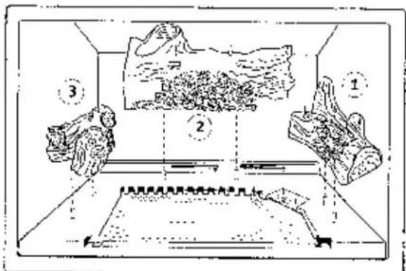
Figure 41. Install Right Log, Rear Log and Left Log in that order.
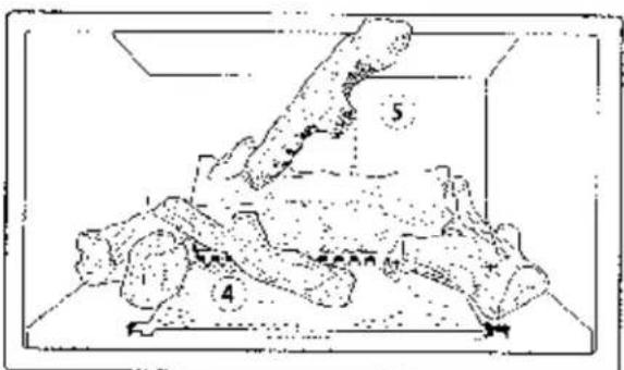
Figure 42. Install Front and Cross over logs as shown.
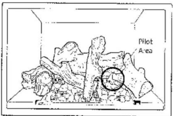
Figure 43. Install ember stones, keeping clearance around the pilot crossover area.
Surround Assembly
- Cut and remove the plastic wire tie from the Lower Grille / Control Door and open the door.
- Install each of the Side castings onto the cabinet by engaging the hanger tabs with the holes in the cabinet frame. See fig. 52 for orientation. You may wish to secure each side panel to the bottom of the fireplace cabinet using the MG flat head screw already installed at those locations. It will be necessary to remove the Control Door first.
- Install the Right and Left Upper Grill plates.
- Attach the Inner Panel to the Center Plate. The Inner Panel may be reversed to show the winter scene. (Note: Blue Black Panel is a nameiled on one side only).
- Hang the Center Plate in position.
Optional Double Door
The Double Door set is fully assembled and requires no tools for installation. Use the 4 mm hex key supplied with the doors to adjust the door alignment at the eight socket head hinge screws.
Door Installation
Unpack the door set and inspect the parts for damage. Notify your dealer if any damage is found.
You may wish to remove the doors from the frame to lighten the assembly and case installation. They simply lift off of the hinges.
The door assembly attaches to the fireplace by engaging the three slots in the upper frame with the corresponding steel tabs at the top of the firebox. See fig. 45.
A dl r ple located on the inside of the frame at each lower corner engages with corresponding holes in the glass frame to hold the bottom of the door assembly securely to the firebox. See A, fig. 46.
- Open the Control Access Door. Hang the door frame onto the firebox by engaging the tabs with the holes in the frames. See fig. 45.
- Push the frame over to one side and engage the dimple on that lower corner with the hole in the side of the glass frame. You will feel it lock into place.
- Push the frame assembly over to the opposite side and push that lower corner down to engage with the firebox.
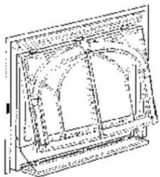
natural_image
Technical line drawing of a framed architectural structure with arched windows (no text or symbols)Figure 45. Hang the frame on the cabinet.
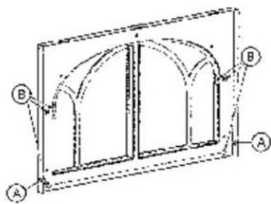
Figure 46. Rear view of door frame.
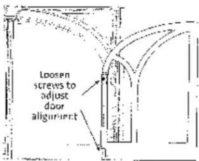
Figure 47. Door adjustment points.
Door Alignment Adjustment
You can adjust the door alignment if necessary by loosening the hinge screws (See 3, fig. 46 and fig. 47). Realign the door and then tighten the screws.
System Check
-
PURGING THE GAS LINE: When lighting the appliance for the first time it will take a few moments to clear the gas line of air. Once this purge is complete, the appliance will operate as described in the lighting instructions located on the fireplace's racing plate and back cover of this manual.
-
PILOT FLAME: The pilot flame should be steady, not lifting or floating. The flame should be blue in color around the pilot hood, with traces of yellow toward the outer edges. It is imperative that the pilot flame engulf the top 3/8" of the thermopile (power generator) and the top 1/8" of the quick drop out thermocouple. The pilot flame should project out of the pilot hood 1" at all three parts. See Figure 48.
-
BURNER ADJUSTMENT: Your Jøtul G2550 Acadia gas fireplace is equipped with a variable gas control valve. This valve provides easy adjustment of the flame height appearance and heat output. To adjust the flame between the HI and LO setting, rotate the HI/LO knob, located in the center of the valve face. Flame height will adjust approximately 1.0" to 1.5" between the HI and LO settings.
NO SMOKE OR SCOT SHOULD BE PRESENT. CHECK LOG PLACEMENT IF ANY SOOT OR SMOKE IS DETECTED. IF SOOT OR SMOKE PERSISTS, THE AIR SHUTTER MAY NEED TO BE ADJUSTED.
CAUTION: DO NOT ATTEMPT TO ALTER THE FLAME APPEARANCE BY POSITIONING THE GAS VALVE IN ANY OTHER POSITION OTHER THAN THE FULL "ON" POSITION.
Flame Appearance / Air Shutter Adjustment
THE ACADIA GAS FIREPLACE IS SHIPPED FROM THE FACTORY EQUIPPED TO USE NATURAL GAS. IF THE BURNER HAS BEEN CONVERTED FOR USE WITH PROPANE, IT WILL BE NECESSARY TO ADJUST THE AIR SHUTTER ON THE BURNER TUBE TO ACH EVE THE PROPER GAS TO AIR MIX. See Figure 26.
WARNING: AIR SHUTTER ADJUSTMENTS SHOULD ONLY BE PERFORMED BY A QUALIFIED PROFES- SIONAL SERVICE TECHNICIAN.
The air shutter adjustment can also help achieve the desired flame appearance. Generally, flame appearance is a matter of individual preference, however a warm yellowish flame is most common. See fig. 49.
Closing the air shutter - will generate very long yellow flames resulting in soot. Sooting produces black deposits on the logs, on the inside walls of the appliance, and potentially on the exterior termination cap.
Socting is caused by incomplete combustion in the flames and lack of combustion air entering the air shutter opening.
Opening the air shutter - will generate a flame that is blue and transparent, or an "anemic" flame. This flame is generally more efficient but not as pretty.
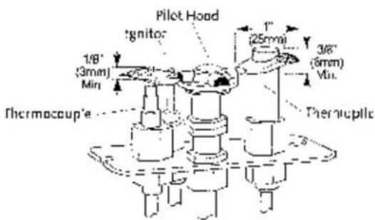
Figure 48 Correct Pilot Flame Pattern
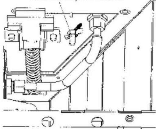
Air Shutter Adjustment
- Open the Lower Grill panel and locate the Air Shuttle: adjustment stem extending down from the right side of the firebox floor. See figs. 49.
- Loosen the locknut and push the stem BACK (to the rear of the firebox) to open the air inlet increasing airflow into the burrer. Push the stem FORWARD to decrease the air inlet. Make adjustments in 1/8" (3 mm) increments and allow time for flame pattern to respond to the new setting. Retighten the locknut when the desired flame pattern is established.
- Reassemble the fireplace including glass assembly. Allow the fireplace to burn 15 -20 minutes on the H'GH setting, observing the flame continuously.
- If the flame appears weak, slow, or sooty, repeat the process described above until the flame is as desired.
Air Inlet Settings
Natural Gas · 1/4" open
Propane - 1/2" open
IMPORTANT: Run the fireplace for a minimum of 15 to 20 minutes to produce an accurate representation of the flame appearance. This warm-up should be done before and between any air shutter adjustment.
Air Shutter Adjustment Stem
natural_image
Technical line drawing of a mechanical assembly with pipes and components (no text or symbols)Figure 49. Air Shutter adjustment location.
natural_image
Black-and-white illustration of a stylized animal or mythical creature with multiple wings and a human figure, surrounded by dense foliage (no text or symbols)Figure 50. Proper flame pattern.
Operation
- Your Acadia gas fireplace can be operated manually using the On/Off/T-stat rocker switch or it can be automatically controlled using an optional wall-mounted thermosLal and/or remote control device. A separate switch is provided for the optional forced air blower kit.
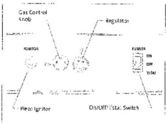
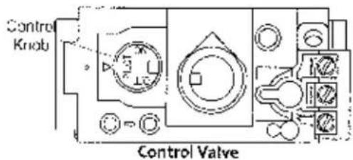
Familiarize yourself with the location and function of the controls. See Figs. 51 and 52.
Gas Control - Used to control the Pilot Light and gas flow from the supply line.
Regulator - Allows you to adjust heat output and flare intensity.
Piezo Ignitor - Push button pilot light ignition.
ON/OFF/T*STAT Switch. Allows for manual or thermostatic control of the burner.
Always follow the Lighting Instructions located on the inside Back Cover of this manual.
-
For the first: several hours of operation, it is common that you will detect some odor as the metal and manufacturing materials cure under heat. This condition is temporary and can be alleviated by allowing plenty of fresh air to circulate through the area.
-
Condensation may develop on the glass upon each lighting of the appliance. This "fog" will disappear as the glass heats.
-
Keep the controls and the area under the appliance free of debris; vacuum this area frequently. Always keep the appliance area clear and free from combustible materials, gasoline and other flammable liquids.
When a vacuum is used on any service for the fireplace, ALWAYS be sure the fireplace is completely cold.
-
Remember, your fireplace utilizes a continuously burning pilot flame. Exercise caution when using household products containing combustible vapors.
-
CAUTION: DO NOT OPERATE THIS APPLIANCE WITH THE GLASS REMOVED, CRACKED OR BROKEN. REPLACEMENT OF THE GLASS SHOULD BE DONE BY A LICENSED OR QUALIFIED SERVICE PERSON. USE ONLY REPLACEMENT GLASS PROVIDED BY YOUR AUTHORIZED J∅TUL DEALER. NEVER USE ANY SUBSTITUTE MATERIALS.
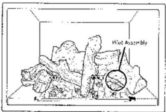
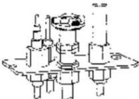
Figure 51. The pilot assembly is located at the right rear corner of the burner plate under the right log.
flowchart
graph TD
    A["Ignitor"] --> B["Regulator"]
    B --> C["FANER"]
    C --> D["ON"]
    C --> E["OFF"]
    C --> F["IS/FAT"]
    G["Pieze Ignitor"] --> A
    H["Gas Control Knob"] --> A
    I["O:1/Off: 'I':sta: Switch"] --> C
Figure 52. Burner Controls.
WARNING: OBSERVE CAUTION NEAR THE GLASS PANEL. THE GLASS MAY SHATTER WHEN STRUCK BY AN OBJECT. ALWAYS HANDLE THE GLASS PANEL WITH CARE.
Maintenance
The Acacia gas fireplace and its venting system should be inspected before use and at least annually by a qualified service technician.
IMPORTANT:
ALWAYS TURN OFF THE GAS SUPPLY TO THE FIREPLACE AND UNPLUG THE FORCED AIR BLOWER BEFORE ANY SERVICE WORK IS PERFORMED ON THE FIREPLACE.
General Cleaning
The firebox should be vacuumed annually to remove any surface build up. Use a soft brush attachment and handle the logs carefully as they are fragile. Be sure to vacuum or wipe off the pilot assembly and burner orifice and burner tube.
Glass Care
Clean the glass only when necessary. Wipe the surface with a clean, dampened, soft cloth. Follow with a dry, soft towel. Take care not to scratch the glass surface.
WARNING:
DO NOT USE ABRASIVE CLEANERS ON THE GLASS. NEVER CLEAN THE GLASS WHEN IT IS HOT.
Gasket Inspection
It is important that the glass gasket be inspected at least annually. Examine the ribbon gasket for signs of deterioration and make sure the gasket has a positive seal. Replace the gasket if necessary. Refer to the replacement parts list on page 28.
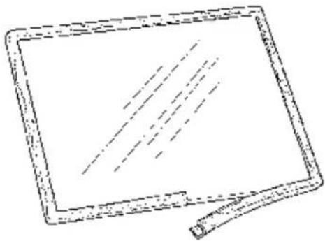
Glass Panel or Gasket Removal
- Open the Lower Grill Panel.
- Release the glass clips at either side of the bottom of the fire box.
- Swing the bottom of the glass frame out and lift to disengage it from the three retainer tabs at the top of the firebox.
- Lay the assembly on a flat surface and carefully lift the metal labs that secure the glass panel to the frame. Remove the old gasket material.
5 Install the new glass panel and gasket in the glass frame and secure with metal tabs. Do not over tighten tabs as that may damage the glass.
ONLY USE J∅TUL AUTHORIZED PARTS. NEVER SUBSTITUTE NON-J∅TUL PARTS ON THIS FIREPLACE.
natural_image
Simple line drawing of a rectangular board with dashed lines and a pen tip (no text or symbols)Figure 53. Replacing the glass gasket.
RETNIN THIS MANUAL FOR REFERENCE AND MAKE IT AVAILABLE TO ANYONE USING OR SERVICING THE FIREPLACE.
MODEL NAME: GZ 550 DV Acadia Gas Fireplace
SERIAL NUMBER:____ ____
DATE OF PURCHASE:
AUTHORIZED DEALER:
NAME OF INSTALLER:____
TYPE OF FUEL:
WAS FIREPLACE CON- VERTED?____
NOTES:
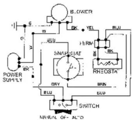
Figure 54. ZG550 DV Acadia Blower Wiring Diagram
SERVICE LOG: First Year
Name of Technician.
Company Name: ____
Date of service____.
Work Performed____
SERVICE LOG: Second Year
Name of Technician____ ____
Company Name____ ____
Date of service____
Work Performed
SERVICE LOG: Third Year
Name of Technician____
Company Name____.
Date of service____
Work Performed ____
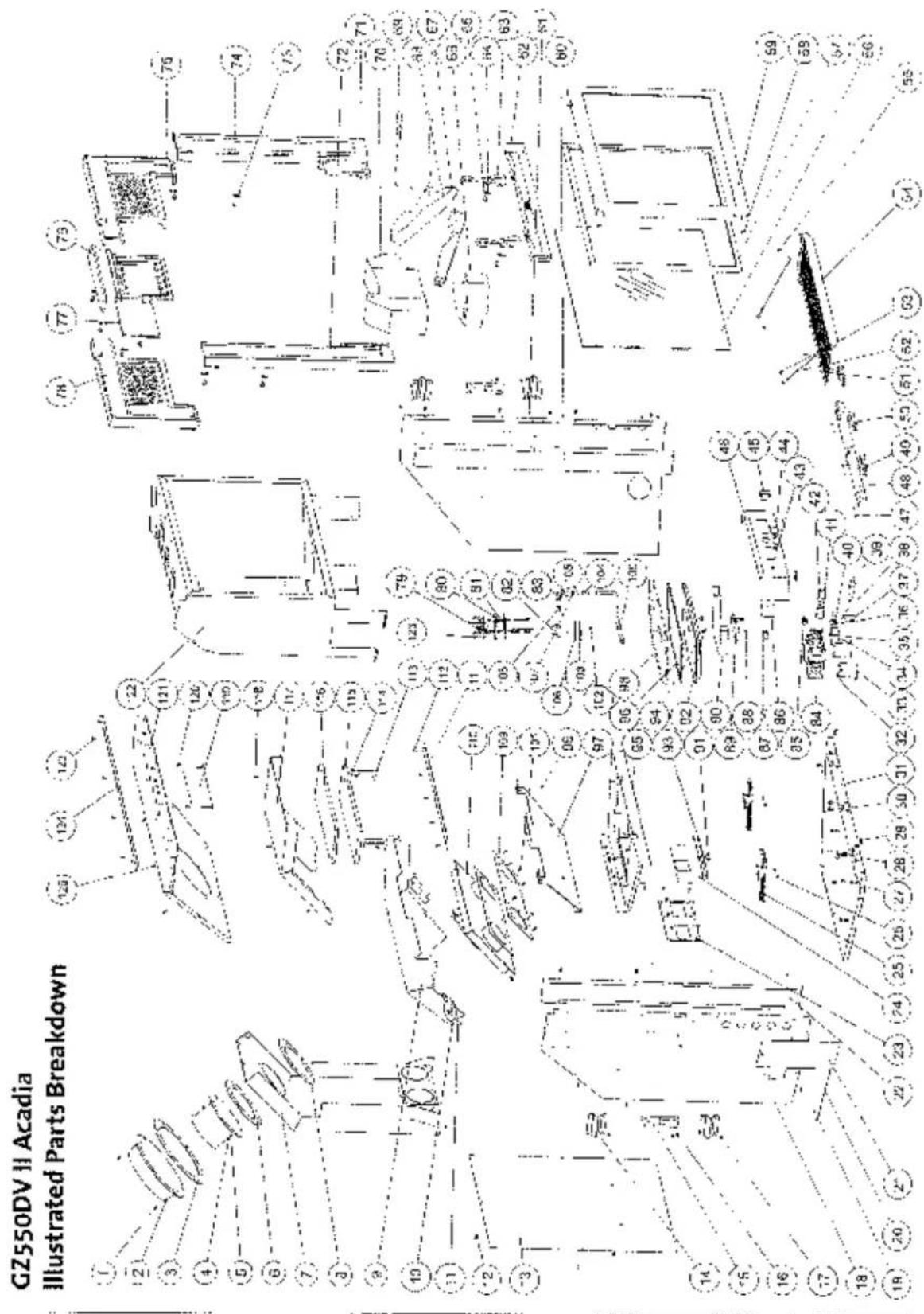
GZ 550 DVII Acadia Parts
| No. | Description | Port Number |
| 1. | Screw, 98 x 1/2 5" sheet metal | 117917 |
| 2. | Acaptor, 8" | 129784 |
| 3. | Casket, 8" Adaptor | 129775 |
| 4. | M5 Hex Nut | 9930 |
| 5. | Acceptor, 5" | 129787 |
| 6. | Casket, 5" Adaptor | 129776 |
| 7. | Air intake Macfoid | 220952 |
| 8. | Gasket, 5" Adaptor | 129774 |
| 9. | Top Shroue, Level 1 | 220953 |
| 10. | Screw, 98 x 1/2" Sheet metal | 129717 |
| 11. | Support Rearset | 220964 |
| 12. | Screw, 98 x 1/2" Sheet metal | 129757 |
| 13. | Cabinet Wall, Rear | 220961 |
| 14. | Stand-2tt, 2" Flaming | 220969 |
| 15. | Walls, 1d Brace | 220915 |
| 16. | Screw, 98 x 1/2" Sheet metal | 117917 |
| 17. | Screw, 98 x 1/2" Sheet metal | 117917 |
| 18. | Cohinct Wall, Left | 220959 |
| 19. | Rivel, 125 x 730 | 117946 |
| 20. | Lanyard, 06 L Wire (Rating Plate) | 129159 |
| 21. | Rolling Plate | 220913 |
| 22. | Coul Air Channel | 220957 |
| 23. | A-I Intake Gasket | 129773 |
| 24. | Air intake Restrictor Plate | 220963 |
| 25. | Latch Assembly | 220049 |
| 26. | M6 Hex Nut | 9910 |
| 27. | M6 Hex Nut | 9930 |
| 28. | M6 Wingnut | 129735 |
| 29. | M6 x 12 Flat Head Phillips Screw | 129767 |
| 30. | M6 x 12 Flex Bolt | 117130 |
| 31. | Cannel Base | 220958 |
| 32. | 10-32 x 3/8" Phillips Screw | 117911 |
| 33. | Valve Bracket | 220945 |
| 34. | Termira Block Bracket | 220930 |
| 35. | M6 Hex Nut | 117922 |
| 36. | Terminal Block, Z Pole | 129154 |
| 37. | Ignitor Bracket | 129679 |
| 38. | M1 x A Phillips Screw | 129720 |
| 39. | Ignitor | 3902573 |
| 40. | M4 x 12 Phillips Screw | 129754 |
| 41. | Knob Extension On/Off | 129729 |
| 42. | Knob Extension Pilto | 129750 |
| 43. | Kheostat Nut | 220777 |
| 44. | Knob #costat Control | 220769 |
| 45. | On / Off Switch | 220763 |
| 46. | Controls Board | 220344 |
| 47. | M4 Hex Nut | 117927 |
| 48. | Ligge Adaptor | 1297934 |
| 49. | M4 x 12 Hex Bell | 117921 |
| 50. | Control Door Hinge | 220543 |
| 51. | M5 x 1C Screw | 129770 |
| 52. | Lanyard, 05/ Wire Control Door | 220574 |
| 53. | Screw, 98 x 1/2" Sheet metal | 129757 |
| 54. | Control Door - Matte Black | 1095894 |
| Control Door - Blue Black | 1035527 | |
| Control Door - Jetul on Gray | 1035585 | |
| 55. | M5 x 10 Screw | 117970 |
| 56. | Ceramix Class Replacement (inc. gasket) | 154987 |
| 57. | Basket, Glass Tadpole | 129175 |
| 58. | Class Lip Innerman | 220047 |
| 59. | Class Frame | 129757 |
| 60. | Cac Air Channel | 220957 |
| 61. | Cabinet Well Right | 220960 |
| 62. | Fettle, Blue Black Enamel | 2205062 |
| 63. | Amilimn, Blue Black Enamel | 1019672 |
| 64. | Hang, Sab | 129783 |
| 65. | M6 x 12 Hex Bull | 12730 |
| 66. | Leg, Left | 220993 |
| 67. | Leg, Front | 220995 |
| 68. | Log Cross-over | 120701 |
| 69. | Log 8 ght | 120994 |
| 70. | Log Rear | 220994 |
| 71. | Surround Log Right / Matte Black | 10395792 |
| Surround Leg Right / Blue Black | 10395727 | |
| Surround Leg Right / Left Iron | 10395785 | |
| 72. | Surround Log Left / Matte Black | 10395797 |
| Surround Log Left / Blue Black | 10395797 | |
| Surround Log Left / Left Iron | 10395785 | |
| 73. | Hang 1st | 123680 |
| 74. | MG x 1/2 Hex Folk | 123680 |
| 75. | Surround Broastplate, Right / Matte Black | 10395851 |
| Surround Broastplate, Right / Blue Black | 10395827 | |
| Surround Broastplate, Right / Left Iron | 10395885 | |
| 76. | Surround Keystone / Matte Black | 10395301 |
| Surround Keystone / Blue Black | 10395327 | |
| Surround Keystone / Jatull Iron | 10395385 | |
| 77. | Tablet / Matte Black | 10396697 |
| Tablet / Blue Black | 10396627 | |
| Tablet / Jatull Iron | 10396635 | |
| 78. | Surround Breastplate, Left / Matte Black | 10395492 |
| Surround Breastplate, Left / Blue Black | 10395477 | |
| Surround Breastplate, Left / Jatull Iron | 10395485 | |
| 79. | Plot Assembly - NL | 123475 |
| 80. | Space Pilot Assembly | 227545 |
| 81. | Basket, Plot Assembly | 129670 |
| 82. | Piloty Air Shutter Assembly | 227530 |
| 83. | Oil le nu dei | 179568 |
| 84. | Cas Valve - NG (50% TD) | 220340 |
| 85. | Compression Nipple, 3/8 NTP - 5/16 | 220044 |
| 86. | Rheastat Assembly | 155831 |
| 87. | Wire Harness Assembly | 155830 |
| 88. | MS x 20 Hex Boil | 117-17 |
| 89. | Tube Holder, Cast Iron | 1550-2 |
| 90. | Venture Tube | 1556-2 |
| 91. | MS Wingnut | 217975 |
| 92. | MS AS Series Taliener | 2156-2 |
| 93. | Casket, Air Intake Restrictor | 220987 |
| 94. | Burner Rose, Cast Iron | 1556-2 |
| 95. | Subfloor - Burner Skirt | 320783 |
| 96. | Casket, Burner | 1556-2 |
| 97. | Exhaust Baffle | 220954 |
| 98. | Burrer Plate Assembly | 255012 |
| 99. | MB Flex Nut | 9930 |
| 100. | Hex Tube, 3/16" x 14" | 129390 |
| 101. | 49 x 1/2" Sheet metal Screw | 117917 |
| 102. | M6 Wingnut | 117975 |
| 103. | Cover Plate, Primary Air Restrictor | 220488 |
| 104. | Compression Nut - 5/15 | 129164 |
| 105. | Compressor Slockc - 5/16 | 129463 |
| 106. | Gasket, Cover Flate | 220395 |
| 107. | Arm Nut | 220157 |
| 108. | Officer, 4/18 - NC | 129130 |
| Officer, 1.55 - LP | 220048 | |
| 109. | Casket, Heat Exchange | 129673 |
| 110. | Heat Exchanger | 220950 |
| 111. | Class Frame Hangers | 129760 |
| 117. | 48 x 1/2" Sleet metal Screw | 117517 |
| 115. | Relief Door Guide | 120204 |
| 114. | PS x 1/2" Sheet Metal Screw | 117917 |
| 115. | Gasket, Relay Door | 129777 |
| 116. | Relief Door | 129729 |
| 117. | Top Shroud, Leser | 220955 |
| 118. | 48 x 1/2" Sheet Metal Screw | 127917 |
| 115. | Keystone Heat Shield | 220009 |
| 120. | 88 x 1/2" Sheet Metal Screw | 117917 |
| 121. | Salineal Top | 220962 |
| 122. | Firebox | 220947 |
| 123. | 48 x 1/2" Sheet Metal Screw | 117927 |
| 124. | Slucklrone Standoff | 220789 |
| 125. | 48 x 1/2" Sheet Metal Screw | 117927 |
| 126. | 48 x 1/4" Sheet Metal Screw | 117926 |
| 127. | Air Defector Burner Skirt | 222102 |
| 128. | Embe "Storrs, 4 oz." | 220702 |
| 129. | Therm occuple | 129760 |
| 130. | Flex Irode | 229765 |
| 131. | Thermopile | 1044527 |
'not illustrated
GZ 550 DV II Optional Accessories
• Antique Brick kit 155809
• Variable Speed Blower, 125 / 60 c.f.m. .... 135630
• 4" x 6 5/8" Adapter Kit 154974
• High Altitude Conversion Kit - NG 155640
• High Altitude Conversion Kit - LP 1556:11
• Fuel Conversion Kit - L ^2 155594
• Fuel Conversion Kit - NG 255595
• Wall Thermostat 750003
• Remote Control 129706
- QuickFace Fronts w/ Screen
Steel Rectangular, Matte Black .... 154964
Steel Arch, Matte Black 154965
Brushec Stainless Steel, Rectangular ..... 154968
Brushed Stainless Steel Arch....154969
- Arched Double Doors, Matte Black.... 350560
- Arched Double Doors, Blue Black .... 350561
• Double Door Basket Screen 154973
LIGHTING INSTRUCTIONS
FOR YOUR SAFETY, READ BEFORE LIGHTING.
WARNING:
IF YOU DO NOT FOLLOW THESE INSTRUCTIONS EXACTLY, A FIRE OR EXPLOSION MAY RESULT CAUSING PROPERTY DAMAGE, PERSONAL INJURY, OR LOSS OF LIFE.
A. This appliance has a pilot which must be lit by basic. When fighting the pilot, follow these instructions exactly.
B. BEFORE LIGHTING, smell all around the appliance area for gas. Be sure to smell next to the floor because some gas is heavier than air and will settle to the floor.
WHAT TO DO IF YOU SMELL GAS:
• Extinguish any open flame.
- Open windows.
• Do not light any appliance.
- Do not touch any electrical switches.
• Do not use any phone in your building.
- Immediately call your gas supplier from a neighbor's phone.
- if your gas supplier cannot be reached, call the fire department.
C. Use only your hand to push in or turn the gas control knob. Never use tools. If the knob will not push in or turn by hand, do not try to repair it. Call a qualified technician. Force or attempted repair may result in a fire or explosion.
D. Do not use this appliance if any part has been under water. Immediately call a qualified service technician to inspect the appliance and to replace any part of the control system and any gas control which has been under water.
LIGHTING INSTRUCTIONS
- STOP! Read the safety information above.
- Access the lower controls.
- Turn the stove ON/OFF switch to "OFF", or set the thermostat to lowest setting (if usec).
- Confirm that the gas supply line shut-off valve is open.
- Push in gas control knob slightly and turn clockwise to "OFF".
NOTE: Knob cannot be turned from "PILOT" to "OFF" unless the knob is pushed in slightly. Do not force. -
Wait five (5) minutes to clear out any gas. If you then smell gas, STOP! Follow "It" in the safety information above on this page. If you do not smell gas, go to the next step.
-
Push in gas control knob slightly and turn counterclockwise to "PILOT".
- Push in control knob all the way and hold in. Immediately light the pilot by triggering the spark ignitor (push the red button repeatedly) until pilot lights. Continue to hold the control knob in for
about one minute after the pilot lights. Release knob and it should spring back. The pilot should remain it. If it goes out, repeat Steps 5 through 8. - If knob does not return when released, stop and immediately call your service technician or gas supplier. Pilot Assembly
-
If pilot will not stay lit after several tries, turn the control knows to OFF and call your service technician or gas supplier.
-
Turn gas control knob counterclockwise to "ON".
-
Turn the stove ON/OFF switch to "ON", or se: thermostat (if used) to desired temperature.
natural_image
Technical line drawing of a mechanical assembly with no visible text or symbolsPilot Assembly
TO TURN OFF GAS TO THE APPLIANCE:
- Turn ON/OFF switch to "OFF". The pilot will remain lit for normal service.
-
For complete shutdown, turn ON/OFF switch to "OFF".
-
Access the lower controls.
- Depress gas control knob slightly and turn clockwise → to "OFF". Do not force.
8-05675T 137950-B 900€ KyH
This appliance must be installed in conformance with local and national building regulations. Before beginning the installation, it is important that the these instructions be carefully read and understood. Iptal maintains a policy of continual product development. Consequently, products may differ in specification, color or type of accessories from those illustrated or described in various publications.