GZ 450 DV - Wood stove JOTUL - Free user manual and instructions
Find the device manual for free GZ 450 DV JOTUL in PDF.

User questions about GZ 450 DV JOTUL
0 question about this device. Answer the ones you know or ask your own.
Ask a new question about this device
Download the instructions for your Wood stove in PDF format for free! Find your manual GZ 450 DV - JOTUL and take your electronic device back in hand. On this page are published all the documents necessary for the use of your device. GZ 450 DV by JOTUL.
USER MANUAL GZ 450 DV JOTUL
Atra GZ 450 DV Direct Vent Gas Fireplace
natural_image
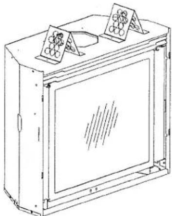
Line drawing of a rectangular device with two hanging triangular components on top (no text or symbols)
Intertek
Installation Manual
for the
Atra Adirondack
GZ 450 DV Fireplaces
WARNING: If the information in these instructions is not followed exactly, a fire or explosion may result causing property damage, personal injury or loss of life.
- Do not store or use gasoline or other flammable vapors and liquids in the vicinity of this or any other appliance.
-
WHAT TO DO IF YOU SMELL GAS
-
Do not try to light any appliance.
- Do not touch any electrical switch; do not use any phone in your building.
- Immediately call your gas supplier from a neighbor's phone. Follow the gas supplier's instructions.
-
If you cannot reach your gas supplier, call the fire department.
-
Installation and service must be performed by a qualified installer, service agency or the gas supplier.
- In the Commonwealth of Massachusetts, a carbon monoxide (CO) detector shall be installed in the same room as the appliance.
This appliance may be installed in an aftermarket, permanently located, manufactured home or mobile home, where not prohibited by local codes.
This appliance is only for use with the types of gas indicated on the rating plate.
ATTENTION : CES INSTRUCTIONS DOIVENT DEMUERER AVEC LE PROPRIÉTERE D'UNE MAISON.
INSTALLER: Leave this manual with the appliance.
CONSUMER: Retain this manual for future reference.
WARNING
natural_image
Abstract grayscale illustration of a globe with continents, no text or symbols presentHOT GLASS WILL CAUSE BURNS.
DO NOT TOUCH GLASS UNTIL COOLED.
natural_image
Abstract grayscale graphic with overlapping circular shapes and a diagonal line (no text or symbols)THIS OWNER'S MANUAL PROVIDES INFORMATION TO ENSURE SAFE INSTALLATION AND EFFICIENT, DEPENDABLE OPERATION OF YOUR FIREPLACE INSERT. PLEASE READ THESE INSTRUCTIONS IN THEIR ENTIRETY AND MAKE THEM AVAILABLE TO ANYONE USING OR SERVICING THIS GAS INSERT.
DO NOT ATTEMPT TO ALTER OR MODIFY THE CONSTRUCTION OF THIS APPLIANCE OR ITS COMPONENTS. ANY MODIFICATION OR ALTERATION WILL VOID THE WARRANTY, CERTIFICATION AND LISTING OF THIS APPLIANCE.
THIS HEATER MUST BE INSTALLED AND MAINTAINED BY A QUALIFIED SERVICE AGENCY.
Suggested Tools for Installation and Service
• External regulator (for Propane only)
- Piping which complies with local code
- Manual shut-off valve - T-Handle required in Massachusetts
- Sediment trap - if required by code
- Tee joint
- Flat head screwdriver
- Pipe wrench
- 1/4" nut driver
- Pipe sealant
- Gloves
• 10 mm open end wrench • Safety glasses - 1/2",7/16" open end wrench
- Torx T-20 screwdriver
• Phillips head screwdriver • Tin snips
Installation Requirements for the Commonwealth of Massachusetts
THIS PRODUCT MUST BE INSTALLED BY A LICENSED MASTER OR JOURNEYMAN PLUMBER OR GAS-FITTER WHEN INSTALLED IN THE COMMONWEALTH OF MASSACHUSETTS.
-
If there is not one already present, on each floor level where there are bedroom(s), a carbon monoxide detector and alarm shall be placed in the living area outside the bedroom(s). The carbon monoxide detector shall comply with NFPA 720 (2005 Edition).
-
A carbon monoxide detector shall:
a) Be located in the room that houses the appliance or equipment;
b) Be either hard-wired or battery powered or both; and
c) Shall comply with NFPA 720 (2002 Edition).
- A Product-approved vent terminal must be used, and if applicable, a Product-approved air intake must be used. Installation shall be in strict compliance with the manufacturer's instructions. A copy of the installation instructions must remain with the appliance or equipment at the completion of the installation.
Massachusetts Product Approval Code G3-0810-37
NATIONAL FIREPLACE INSTITUTE
CERTIFIED
We recommend that our gas products be installed and serviced by professionals who are certified in the U.S. by the National Fireplace Institute® (NFI) as NFI Gas Specialists.
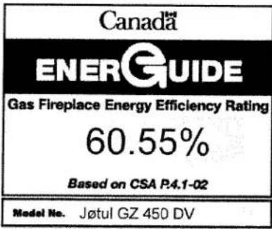

Table of Contents
1.0 Specifications....4
2.0 General Information....5
3.0 Safety Information 6
4.0 Installation Requirements 4.1 Electrical Requirements .... 7
4.2 Fireplace Location 7
4.3 Framing Requirements....8
4.4 Vent Framing Requirements ..... 10
4.5 Hearth Requirements 11
4.6 Fireplace Clearances 11
5.0 Venting Requirements 5.1 Horizontal Termination ....12
5.2 Vertical Termination....14
5.3 Exhaust Restriction .....14
6.0 Fireplace Assembly 6.1 Glass Frame Removal .... 16
6.2 Routing the Power Supply 16
6.3 Gas Connection....17
6.4 Gas Pressure....18
6.5 High Altitude Adjustment....19
6.6 Firebox Panel Installation .....20
6.7 Burner Treatments 21
6.8 Door Assembly 23
6.9 Surround Assembly 23
6.10 System Check 24
6.11 Initial Operation Notes 25
7.0 Operation 7.1 SIT Proflame System Features .... 25
7.2 Control Functions.... 25
8.0 Maintenance 8.1 Annual Cleaning....31
8.2 Glass Care 31
8.3 Gasket Inspection 31
8.4 Glass & Gasket Replacement .....31
8.5 Battery Replacement 32
8.6 Accent Lamp Replacement 32
9.0 Illustrated Replacement Parts.... 33 - 35
10.0 Appendix 10.1 Approved Vent Manufacturers......36
10.2 Mobile Home Installation....36
10.3 Correct Flame Pictures 37
10.4 Wiring Diagram 37
11.0 Warranty Statement 38
12.0 Lighting Instructions ..... Inside Back Cover
Unpacking the Fireplace
-
Inspect the contents. Immediately report any damage to your dealer.
-
Confirm contents.
The Atra GZ 450 DV Fireplace includes the following items shipped inside the firebox and Miscellaneous Hardware bag:
• Simpson Dura-Vent 8 x 6 5/8 Vent Reducer (4/6 Adaptor)
- Latch Tool - used to remove the glass panel to access the firebox and to adjust the exhaust restrictor. See page 16, fig. 25.
- #8 x 1/2" sheet metal screws, 8
• Remote Control Transmitter
• Non-metallic sheath cable clamp
• Ausable Arch Door Shade - attached to the shipping pallet
• Balsam Hanger Bracket - attached to the shipping pallet
- Confirm Firebox Components.
The firebox accessories have been packed in separate boxes, and will include one of each of the following items:
Fireplace Facings
• Ausable Doors: 156867 - Black 156868 - Bronze 156869 - Natural Iron
• Saranac Doors: 156887 - Black 156888 - Bronze
- Placid Surrounds: Arch Style: 157000 - Black 157001 - Bronze Standard Style: 156870 - Black 156871 - Bronze
• Loj Doors: 156889 - Black
• Balsam Surrounds: 156890 - Black Penny Vein - 156891 Gold Vein - 156892
Burner Treatments
• Atra Log Set 156840
- Beach Fire Sculpture 156854
• Forest Floor Sculpture 156860
Firebox Panel Kits
• Fieldstone Panels 156851
• Brick Panels, Buff Beige 156852
• Brick Panels, Chimney Red 156853
- Confirm Fuel Type.
This fireplace has been factory-configured to burn either Natural Gas or Propane. The fuel type is indicated on the shipping label, and on labels applied to the valve compartment and Rating Plate. Be sure that the correct fuel source is available for this appliance.
- Remove Pallet Brackets - one on each side, two at the rear. See fig. 1 below.
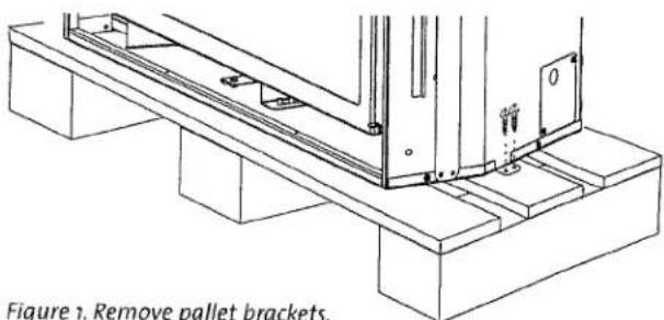
Figure 1. Remove pallet brackets.
GZ 450 DV 138978_Rev_K 6.6.13
1.0 Specifications
1.1 Test Standards
This appliance complies with National Safety standards and is tested and listed by Intertek Testing Services of Middleton, Wisconsin.
In addition, the Atra GZ 450 DV has been tested and listed as a direct vent gas fireplace heater and listed to ANSI Z21.88-2009, CSA 2.33-2009, and CAN/CGA 2.17-M91.

1.2 Rating Specifications
Input Rates
Natural Gas
28,000 BTU/hr. maximum input
19,371 BTU/hr. minimum input
Propane
28,000 BTU/hr. maximum input
19,339 BTU/hr. minimum input
| Inlet Pressure: | MIN | MAX |
| Natural Gas: 4.5 WC (1.12 kPa) | 6.5 WC (1.62 kPa) | |
| Propane: 11.0 WC (2.74 kPa) | 13.0 WC (3.24 kPa) | |
| Manifold Pressure: MIN | MAX | |
| Natural Gas: 1.6 WC (0.40 kPa) | 3.5 WC (0.87 kPa) | |
| Propane: 6.4 WC (1.59 kPa) | 10.0 WC (2.48 kPa) | |
• Steady State Efficiency: 70.0% NG / 69.7% LP
• AFUE Efficiency: 64.0% NG / 70.5% LP
• CSA P4.1-02 Fireplace Efficiency: 60.55%
• Factory Air Shutter Settings: 1/16" NG / 3/16" LP
• Intermittent Pilot Ignition (IPI)
- Continuous Pilot Ignition Mode (CPI or "standing pilot") may also be used
• Power Requirement: 120 VAC, 4 amps for Fan, Lamp, and Burner Control Module
- Remote Control Transmitter batteries preinstalled, 3, AAA - 1.5 v
• Remote Control Receiver batteries supplied: 4, AA
• Fan Control Module: 120V / 60 Hz
1.3 Accessories
High Altitude Adjustment Kit, NG #156879
High Altitude Adjustment Kit, LP #156880
1.4 Finished Facing Dimensions
| Ausable Doors: | 37 3/4" x 31 3/4" | (959 x 806 mm) |
| Saranac Doors: | 37 3/4" x 31 1/2" | (959 x 800 mm) |
| Loj Doors: | 37 3/4" x 31 1/2" | (959 x 800 mm) |
| Placid Fronts: | 37 3/8" x 30 1/4" | (948 x 768 mm) |
| Balsam Surrounds: | 39" x 34 3/4" | (990 x 883 mm) |
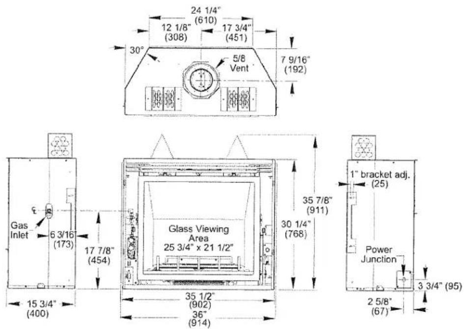
Figure 2. Overall dimensions
2.0 General Information
THIS APPLIANCE MUST BE INSTALLED AND MAINTAINED BY A QUALIFIED SERVICE AGENCY. DO NOT ATTEMPT TO ALTER OR MODIFY THE CONSTRUCTION OF THIS APPLIANCE OR ITS COMPONENTS. ANY MODIFICATION OR ALTERATION WILL VOID THE WARRANTY, CERTIFICATION AND LISTING OF THIS APPLIANCE. WARNING: FAILURE TO POSITION THE PARTS IN ACCORDANCE WITH THE DIAGRAMS HEREIN OR FAILURE TO USE ONLY PARTS SPECIFICALLY APPROVED WITH THIS APPLIANCE MAY RESULT IN PROPERTY DAMAGE OR PERSONAL INJURY.
IMPORTANT: SAVE THESE INSTRUCTIONS.
The installation and repair of this appliance must be done by a qualified service person. Failure to properly install and maintain this heater could result in an unsafe or hazardous installation, which may result in a fire, explosion, property damage, personal injury or loss of life.
This appliance should be inspected before use and at least annually. More frequent cleaning may be required due to excessive lint from carpeting, bedding material, etc. It is imperative that control compartments, burners and circulating air passageways of the appliance be kept clean.
This appliance may be installed in an aftermarket permanently located, manufactured (mobile) home, where not prohibited by local codes. This appliance is only for use with the type(s) of gas indicated on the rating plate. This appliance is not convertible for use with other gases, unless a certified kit is used.
The installation must conform to local codes. Your local Atra authorized dealer can assist you in determining what is required in your area for a safe and legal installation. Some areas require a permit to install a gas burning appliance. Always consult your local building inspector or authority having jurisdiction to determine what regulations apply in your area.
In the absence of local codes, the installation requirements must comply with the current National codes. In the U.S., these requirements are established in the National Fuel Code, ANSI Z223.1.(NFPA 54). In Canada, the codes have been established in CAN/CGA B149 Fuel Installation Code.
■ Do not operate this fireplace if any part of it has been under water..
Immediately call a qualified service technician to inspect the heater and to replace any part of the control system and any gas control which has been under water.
Do not operate the fireplace with the glass front removed, cracked or broken. Replacement of the glass should be done by a licensed or qualified service person. Only remove glass for routine service. Always handle glass carefully.
■ Notify your insurance company before proceeding with installation of this fireplace.
3.0 Safety Information
■ Be aware of electrical wiring locations when cutting holes in walls and ceilings for termination.
The blower must be electrically grounded in accordance with local codes or, in the absence of local codes, with the current ANSI/NFPA 70, National Electrical Code or CSA C22.1-Canadian Electrical Code.
The Blower is supplied with a three-prong (grounding) plug for protection against shock hazard and should be plugged directly into a properly grounded three-prong receptacle. DO NOT CUT OR REMOVE THE GROUNDING PRONG FROM THE PLUG.
■ Always disconnect the power supply when performing routine service on the fireplace.
WARNING!
Shock Hazard. Can cause severe injury or death. This appliance is powered by line voltage. Do not try to repair the components in this appliance. In no way are the component enclosures to be tampered with or opened. Turn off the main power supply at the FCM during installation or when performing any maintenance.
WARNING!
Always shut off the main gas supply to the appliance during inspection, maintenance, or cleaning.
4.0 Installation
4.1 Electrical Requirements
This appliance requires 120 VAC, 4 amps for operation of the Blower, Accent Lamp, and Remote Control functionality.
This appliance power supply must be electrically grounded in accordance with local codes or, in the absence of local codes, with the current ANSI/NFPA 70, National Electrical Code or CSA C22.1-Canadian Electrical Code.
Do not disconnect the lamp and fan power cords from the appliance power supply (Fan Control Module). Use the rocker switch to control power to these parts.
■ Always turn off the main power supply at the Fan Control Module when performing routine service on this appliance.
NOTE: Fireplace control components may be adversely affected by other electrical controls that share the same circuit. If it is not practical to install a dedicated service line to the fireplace, we recommend use of a circuit that is free of dimmers and/or fan speed controls.
4.2 Fireplace Location
In selecting a location for the fireplace, consider the following points:
1) Heat distribution
2) Vent termination requirements
3) Gas supply routing
4) Traffic areas, furniture, draperies, etc.
5) 120V electrical service availability.
This fireplace may be located on or near conventional construction materials, however, proper clearance to combustibles must be maintained in order to provide adequate air circulation around the appliance. Follow the framing and clearance specifications exactly.
The clearances specified in this manual are the minimum requirements established as a result of safety testing. A combustible material is anything that can burn; i.e. sheet rock, wall paper, wood, fabrics, etc. These surfaces are not limited to those that are visible and also include materials that may be located behind non-combustible materials.
If you are not sure of the combustible nature of a material, consult your local fire officials. "Fire-resistant" materials are considered to be combustible. They may be difficult to ignite, but will burn. "Fire-rated" sheet rock is also considered combustible.
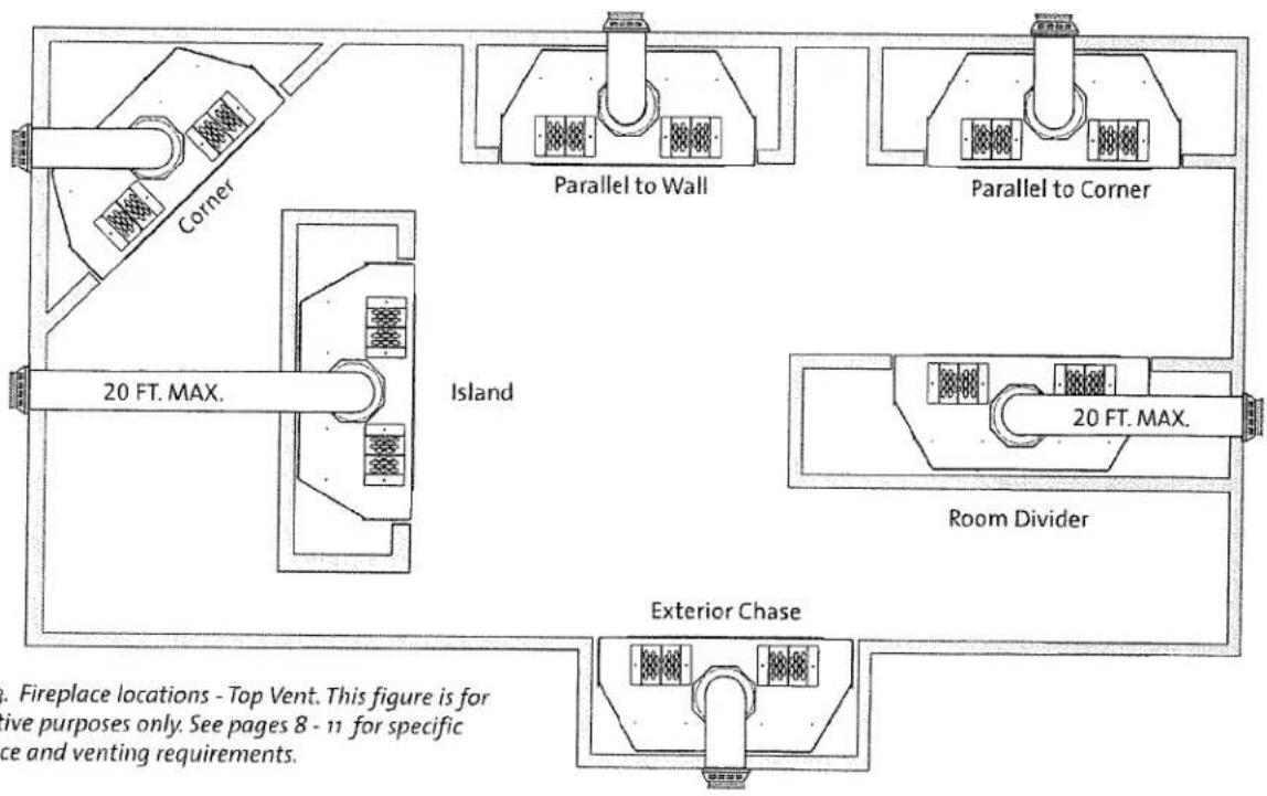
Figure 3. Fireplace locations - Top Vent. This figure is for illustrative purposes only. See pages 8 - 11 for specific clearance and venting requirements.
4.3 Framing Requirements
■ Bend the two header standoffs upright and secure each to the cabinet top with four sheet metal screws provided in the Miscellaneous Hardware Kit. Also, use these screws to install the Ausable Shade or Balsam Hanger Bracket if those front treatments will be used. See figs. 9 - 9a.
The front wall framing will differ depending upon which front treatment will be used. See figs. 4, 5, & 10 regarding framing requirements specific to the Placid fronts, Balsam surrounds, and steel door styles.
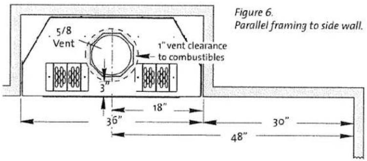
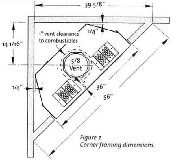
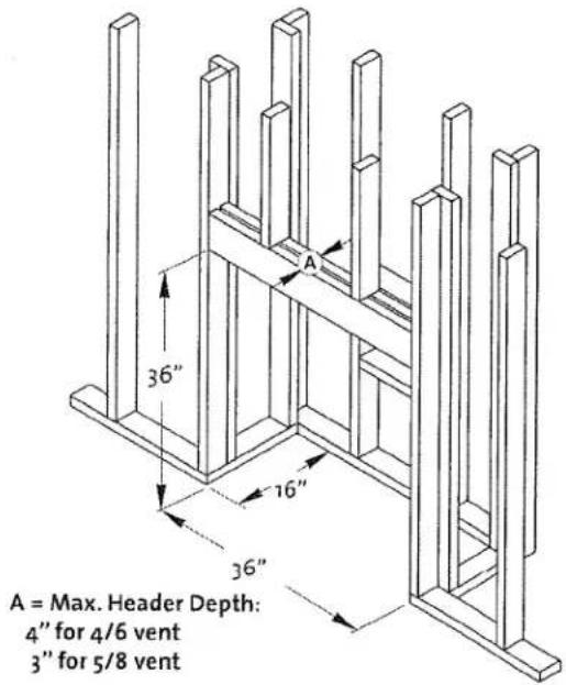
NOTE: Vertical vent runs require that 1 inch clearance to combustible framing members be maintained all around the vent. Therefore, if 5/8 pipe is used, combustible header material must not exceed 3 inch thickness in front of the vent pipe. See figs. 6-8.
Use the included Simpson Duravent 8x6 5/8 Vent Decreaser to transition to 4/6 vent pipe which enables 1" clearance to be maintained with a maximum header thickness of 4 inches. See fig. 12.
The decreaser may not be used on a rear exit vent run.
■ Insulated chase walls should be finished to ensure proper clearance is maintained between vent pipe and construction materials.
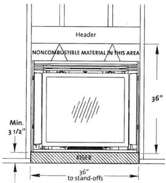
Figure 4. Balsam Surrounds - raised platform requirement.
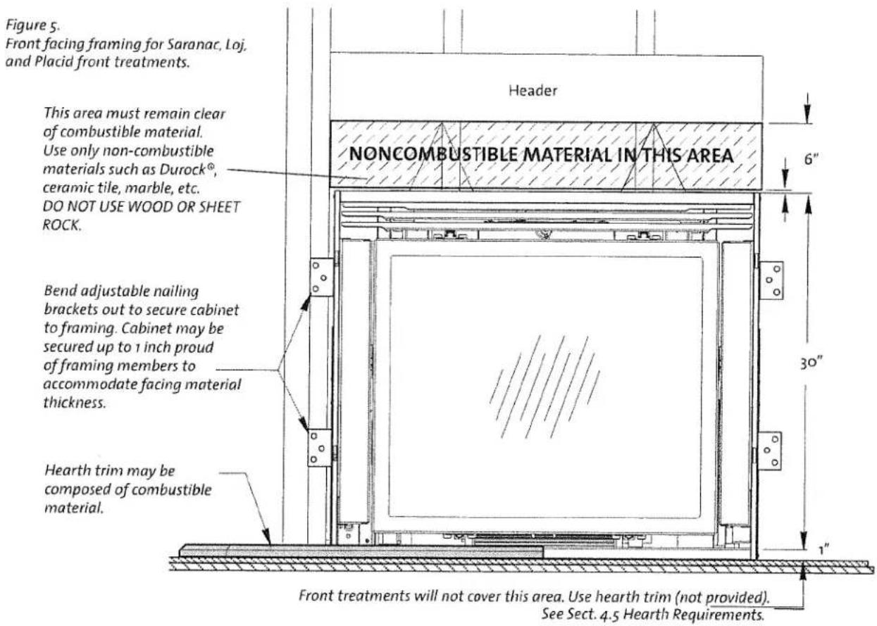
IMPORTANT NOTE: PROPER FIT OF THE PLACID FRONT ASSEMBLY REQUIRES THAT THE FIREPLACE CABINET BE RECESSED AT LEAST 1/4" FROM THE FINISHED WALL FACING.
THIS WILL ACCOMMODATE THE PROTRUSION OF THE SCREEN FASTENERS ON PLACID FRONTS. USE THE ADJUSTABLE NAILING BRACKETS TO ENSURE PROPER ALIGNMENT WITH THE WALL FACE.
See fig. 18, note F, for required terminal clearances to outside corner.
Before installing the fireplace cabinet within the wall ...
Figure 9. Ausable Arched Doors require installation of Arch Shade which is shipped attached to the shipping pallet. Use four #8 sheet metal screws provided in the Miscellaneous Hardware Kit.
Figure 8. Basic chase area framing.
Figure 9a. Use of the Balsam Surround will require installation of the hanger bracket which is shipped attached to the shipping pallet. Use four #8 sheet metal screws provided in the Miscellaneous Hardware Kit.
Figure 10. Noncombustible area when Arched Shade is installed.
4.4 Vent Framing Clearances
Figure 11. 5/8 Horizontal termination with minimum vertical rise. Note pipe clearance from combustible header framing.
Figure 12. 4/6 Horizontal termination with 2 ft. minimum vertical rise. Note pipe clearance from combustible header framing.
Minimum Clearances from the Vent Pipe to Combustible Materials:
Horizontal Run:
Off the top of the vent pipe - 2" (51 mm)
Off the sides and bottom - 1" (25 mm)
Vertical Run:
All sides - 1" (25 mm
Figure 13.
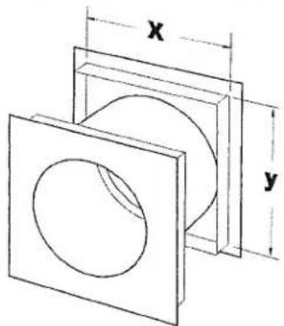
Local codes may require a listed wall thimble be installed according to manufacturer's instructions. Dimensions may vary by manufacturer.
natural_image
Technical drawing of a mechanical component with labeled dimensions x and y (no text or symbols beyond labels)4.5 Hearth Requirements
The Atra GZ 450 DV has been approved for installation directly on combustible floor materials. No additional floor protection is required, however, we recommend that the fireplace be installed on a solid surface and securely fastened to the floor using the base brackets provided at the sides and rear.
NOTE: Door treatments do not cover the front lip of the fireplace base. Any hearth trim used to cover this 1" area can be composed of combustible or non-combustible materials.
4.6 Fireplace Clearance Requirements
Minimum Clearances: See figs. 15-16.
Back: Zero-clearance to standoff
Sides: Zero-clearance to standoff
Top: Zero-clearance to standoff
Ceiling: 72" (1829 mm) - from floor
Ceiling - Chase Enclosure: 45" (1143 mm) from cabinet floor
Corner: 1/4" (7 mm) - from rear corner of unit
Minimum Clearances to Combustible Mantel and Trim Construction*:
Mantel, 3 1/2" depth: 42" (1067 mm) from floor Side Trim, up to 6" depth: 1" (25 mm) from Surround, results in minimum side trim internal width of 39 3/4".
*NOTE: FIREPLACE MANTEL AND TRIM MAY NOT BE USED WITH THE BALSAM SURROUND TREATMENT.
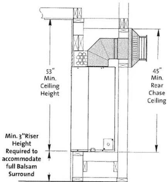
Figure 16. Balsam Surround Only- Ceiling & Framing Clearances.
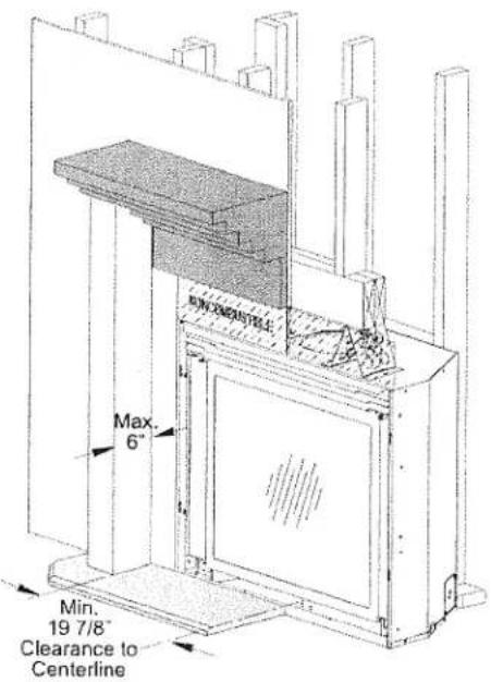
Figure 15. Mantel and Trim construction.
Figure 16a. Mantel and Trim clearance requirements.
5.0 Venting Requirements
There are two types of venting configurations approved for use with this fireplace.
• Vertical Venting / Vertical Termination
• Vertical Venting / Horizontal Termination
■ A 4/6 Vent Adaptor is included with the appliance.
This appliance is approved for use with the 4/6 and 5/8 direct vent systems manufactured by the companies listed in the Appendix on page 36.
■ Use parts of one manufacturer only - DO NOT MIX VENT COMPONENTS FROM DIFFERENT MANUFACTURERS WITHIN THE SAME SYSTEM.
■ Installation of any components not manufactured or approved by Atra or failure to meet all clearance requirements will void all warranties and could result in property damage or bodily injury.
The approved vent configurations described in this manual are derived from extensive testing under controlled laboratory conditions. Gas appliance performance can be negatively affected by variables present in the installation environment, i.e.; atmospheric pressure, strong prevailing winds, adjacent structures and trees, snow accumulation, etc. These conditions should be taken into consideration by the installer and fireplace owner when planning the vent system design.
IMPORTANT
Joint Sealing Requirement Simpson Dura-Vent:
- Apply 1/8" bead of high-temperature, non-silicone sealant or Mil-Pak® to the male section of the inner pipe. The cement should form a seal between the two inner pipe sections. See fig. 17 and the vent manufacturer's instructions.
- Never modify any venting component, or use any damaged venting product.
- The gas appliance and vent system must be vented directly to the outside of the building and never attached to a chimney serving a solid fuel or gas burning appliance. Each direct vent gas appliance must have its own separate vent system. Common vent systems are prohibited.
- If venting system is disassembled for any reason, reinstall per the manufacturer's instructions provided for the initial installation.
5.1 Horizontal Termination
■ Any horizontally terminated vent system that includes a vertical run must terminate with the shaded areas in the diagram in fig. 21. See page 14 for important information regarding exhaust restriction adjustments.
■ 4/6 vent requires a 2 foot minimum vertical rise from the top vent collar. See fig. 12.
5/8 vent may be directed to a horizontal termination with an 90° elbow straight off the top vent collar. See fig 11. The maximum horizontal run directly off the top collar is 2 feet. One 90° or two 45° elbows may be used.
A maximum of three 90° or six 45° elbows may be used in a horizontally terminated, top exit vent system. Whenever possible, use 45° elbows instead a 90° elbow as they offer less restriction to the flow of flue gases and intake air.
■ Reduce the overall horizontal run by 4 feet for each 90° elbow, and 2 feet for each 45° elbow.
■ When two or more elbows are used in a horizontal run, a less restricted setting may be more effective than that indicated by the termination zone diagram.
The termination cap must not be recessed into the wall or siding. Do not fill air space in wall around termination cap with any type of insulation.
■ Wall Cut-out: 4/6 vent requires a 10" x 10" minimum square hole. 5/8 vent requires a minimum 11" X 11" square hole. These cut-outs are adequate for proper pipe clearance through a wall provided the vent is positioned to maintain 2" minimum clearance at the top. A 1" minimum clearance must be maintained to combustible material around the other sides. The wall cut-out must be fully framed in.
■ Any horizontal vent run must be level or have a 1/4" rise for every foot of run toward the termination cap. Vent may not direct downward at any point.
All horizontal terminations must comply with the clearance specifications to adjacent structures as indicated in fig. 18.
Installation of a Vinyl Siding Standoff is required to prevent damage to vinyl siding between the vent cap and the exterior wall.
A horizontal termination cap must maintain a 3 inch clearance to any overhead combustible materials that project 2 1/2 inches or less. Projections exceeding 2 1/2 inches require a minimum 12 inch clearance to the edge of the vent termination. See fig. 19.
Vinyl siding projections require a default clearance of 18 inches to the top of the vent terminal.
Figure 18. Horizontal termination clearances.

Vent Terminal

Air Supply

Terminals Prohibited in this Area
A = Clearance above grade, veranda, porch, deck, or balcony : 12 inches (30 cm) minimum.
B = Clearance to window or door that may be opened:
**Min. 9 inches, U.S. / *12 inches (30 cm) CAN.
We recommend 12 in. minimum to prevent condensation on the window.
C = Clearance to permanently closed window:
**Min. 9 inches, U.S. / *12 inches (30 cm) CAN
We recommend 12 in. minimum to prevent condensation on the window.
D = Vertical clearance from the top of the termination to a ventilated soffit located above the terminal within a horizontal distance of 2 feet (60 cm) from the center line of the terminal; 18 inches (46 cm) minimum.
E = Clearance to unventilated soffit: 12 inches (30 cm) minimum.
F = Clearance to outside corner: **Min. 9 inches, U.S. / *12 inches (30 cm) CAN. We strongly recommend 12 inches, particularly where windy conditions prevail.
G = Clearance to inside corner: ** Min. 6 inches, U.S. /
*12 inches (30 cm) CAN. We strongly recommend 12 inches, particularly where windy conditions prevail.
* In accordance with CSA B149 Installation Codes.
** In accordance with the current ANSI Z223.1/NFPA 54, National Fuel Gas Code. Note: Local Codes and Regulations may require different clearances.
NOTE: Clearances must be in accordance with local installation codes and the requirements of the gas supplier.
H = *Not to be installed within 15 feet (4.5 m) above a meter/regulator assembly within 3 feet (90 cm) horizontally from the center line of the regulator.
I = Clearance to service regulator vent outlet: 3 feet (91 cm) minimum.
J = Clearance to non-mechanical air supply inlet to building or the combustion air inlet to any other appliance:
12 inches (30 cm) minimum.
K = Clearance to a mechanical air supply inlet:
**Min. 3 feet (91 cm) above if within 10 feet horizontally, U.S. /
*6 feet (1.83 m) minimum / CAN
L = ' Clearance above paved sidewalk or a paved driveway located on public property: 7 feet (2.1 m) min.
M = Clearance under veranda, porch, deck, or balcony: 12 inches (30 cm) minimum. ^2
N = Clearance to propane tank relief valve and filler connection***:
5 feet (1.52 m) minimum to tanks not filled on site
10 feet (3.05 m) minimum to tanks filled on site from bulk truck.
A vent shall not terminate directly above a sidewalk or driveway which is located between two single family dwellings and serves both dwellings.
* Only permitted if veranda, porch, deck, or balcony, is fully open on a minimum of two sides beneath the floor.*
Figure 19.
Termination clearance to overhangs.
5.2 Vertical Termination
This appliance can be vertically vented through a roof or ceiling following these guidelines:
■ The termination must fall within any of the shaded areas in the termination diagram, fig. 21 on page 15.
■ Steep roofs, nearby trees, or predominantly windy conditions, can promote poor draft or down draft conditions. In such cases, an increase to the height of the vent may improve performance.
A maximum of three 90° or six 45° elbows may be used in a vertical termination. Whenever possible, use 45° elbows instead of 90° elbows as they offer less restriction to the flow of flue gases and intake air.
If an offset or elbow is necessary in the vertical rise, the vent pipe must be supported every three feet to avoid excessive stress on the offsets. Use listed Wall Straps from any of the approved vent suppliers.
■ Reduce the overall horizontal run by 4 feet for each 90° elbow, and 2 feet for each 45° elbow.
■ When two or more elbows are used in a horizontal run, a less restricted setting may be more effective than that indicated by the termination zone diagram.
A listed firestop is required at any floor penetration. The opening should be framed in according to the manufacturer's instructions.
■ Always maintain a minimum 1" clearance from all sides of the vertical vent system to any combustible material.
■ Any horizontal vent run must incorporate a 1/4" rise per foot. In no case may vent runs be oriented downward.
GAS VENT HEIGHT: In no case shall any discharge opening on the cap be less than 18" (457 mm) horizontally from the roof surface. See fig. 20.
Maximum Vent Height: 50 ft. above the appliance.
Minimum Vent Height: 6 ft. above the appliance.
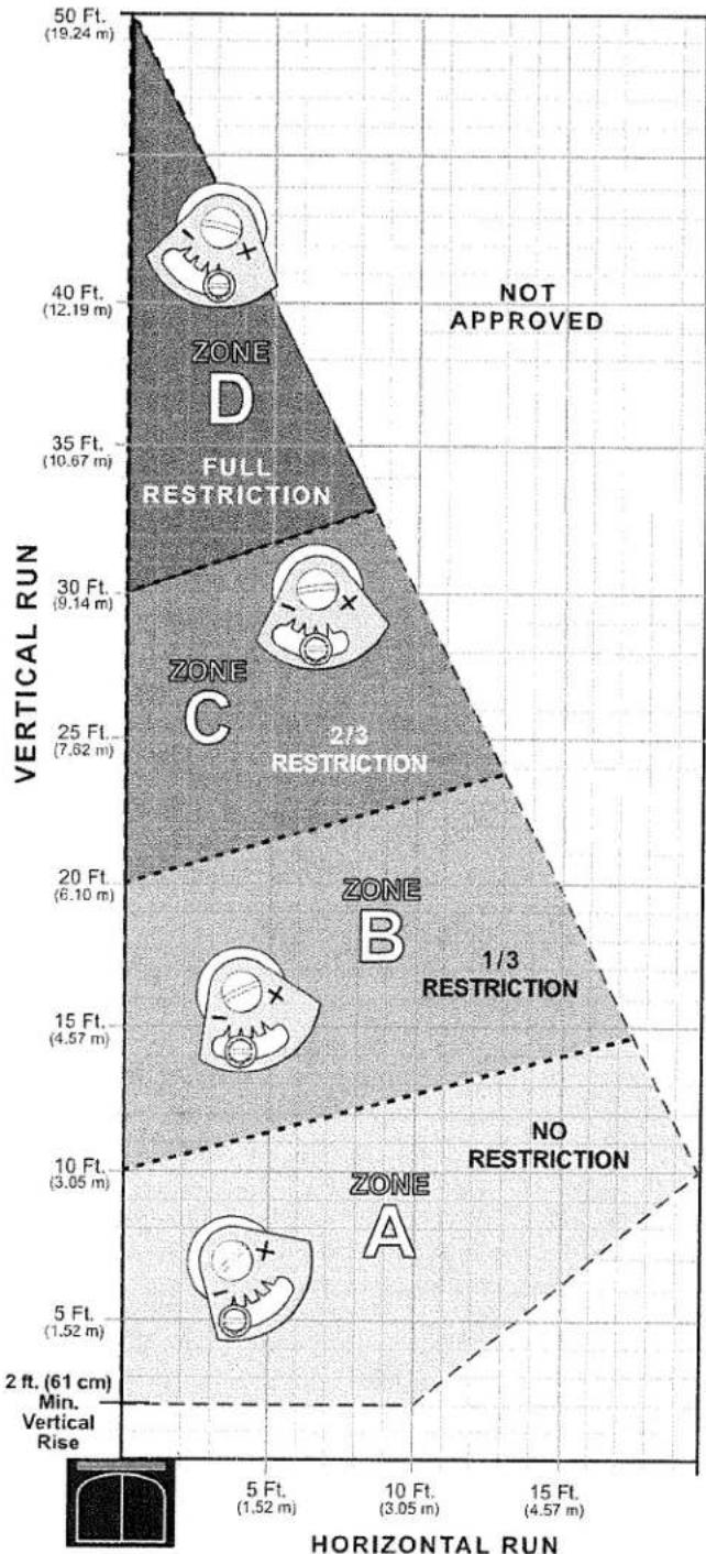
5.3 Exhaust Restriction Adjustments
The Atra GZ 450 DV features an exhaust adjustment control to accommodate a variety of conditions that result from variables inherent in the vent configuration and environment. The control mechanism is a butterfly valve located in the outlet at the top of the firebox. The restriction setting can be accessed from outside the firebox to allow the burner and pilot flame characteristics to be "dialed-in" under operation. See fig. 22.
Exhaust restriction prevents overly strong draft that can interfere with pilot function, cause poor combustion or a weak flame picture.
NOTE: The restrictor valve is set FULLY OPEN at the factory. Use the Vent Termination Diagram, fig. 21, to determine which zone your vent termination falls within and make the appropriate exhaust setting adjustment. Consider this setting to be a starting point, from which further adjustments may be required depending upon the individual characteristics of your particular installation. There are no hard and fast rules.
For example, if the vent vertical rise is 22 feet and includes two 45° elbows in a horizontal run of 10 feet, the termination falls within Zone C after deducting 2 ft. for each elbow from the horizontal run. As this represents a borderline situation, the less restrictive setting in Zone B may offer better performance.
Use of elbows may adversely affect IPI (intermittent pilot ignition) functionality. In such cases, CPI (continuous pilot ignition) mode should be used.
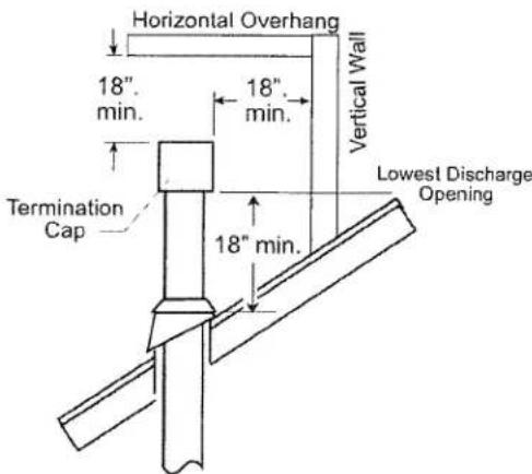
Figure 20. Minimum roof penetration height and clearance from adjacent surfaces - vertical termination.
area
| Vertical Run | Horizontal Run Range (m) | | ------------ | ------------------------ | | 50 Ft. | 19.24 | | 40 Ft. | 12.19 | | 35 Ft. | 10.67 | | 30 Ft. | 9.14 | | 25 Ft. | 7.62 | | 20 Ft. | 6.10 | | 15 Ft. | 4.57 | | 10 Ft. | 3.05 | | 5 Ft. | 1.52 | | 2 ft. | 61 |Figure 21. Top Exit, Vertical or Horizontal Vent Termination Diagram.
5.3.1 Exhaust Restrictor Adjustment
- Use the spade end of the Latch Tool to loosen the locking screw and turn the adjustment screw on the restrictor pivot plate to the appropriate indicator point, as specified in the vent window diagram, figure 21.
The restriction can also be adjusted while the burner is operating if necessary. After the burner has been operating for 15 minutes, make any further adjustment in 1/8" increments until the desired flame picture is achieved. Operate the burner for 10-15 minutes between additional adjustments.
- Retighten the locking screw.
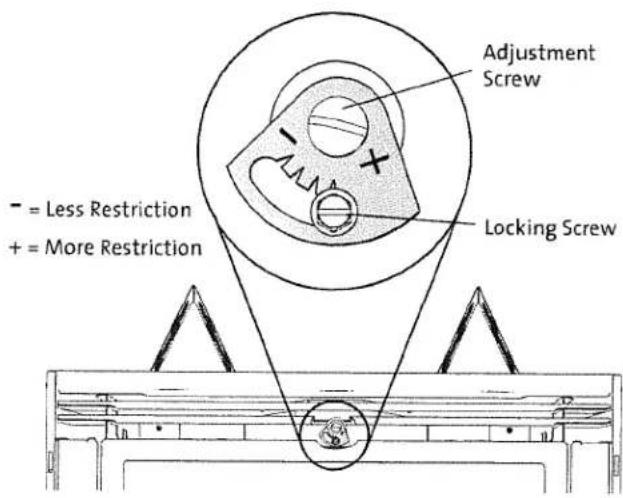
Figure 22. Exhaust restrictor location.
6.0 Fireplace Assembly
6.1 Glass Frame Removal
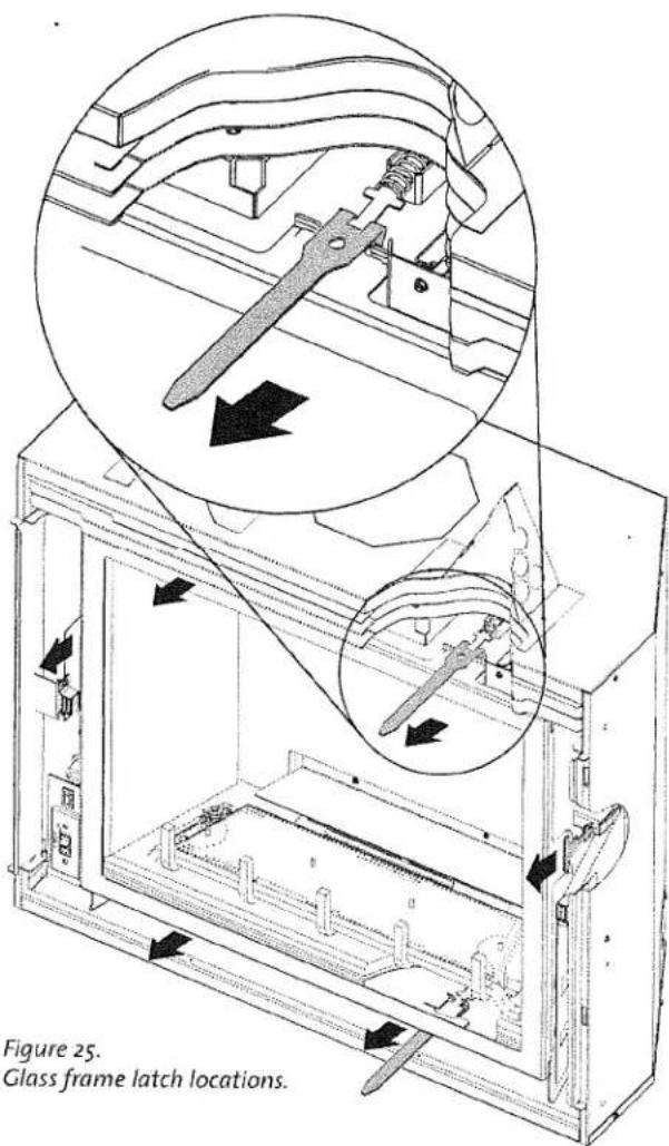
To access the firebox, use the Latch Tool to release the spring loaded glass frame latches. There are two upper, two lower, and one at each side. See fig. 25.
Engage the forked end of the tool with the latch arm and pull back and up to disengage the arm from the frame.
6.2 Routing the Power Supply
HARD WIRING REQUIREMENT
As this appliance is permanently framed into an enclosure, it must be hard wired to 120 VAC house current at the fireplace junction box located at the right rear corner of the cabinet.
This fireplace must be electrically connected and grounded in accordance with local codes. In the absence of local codes, use the current ANSI/NFPA 70-1996 NATIONAL ELECTRICAL CODE IN THE U.S. OR CSA C22.1 CANADIAN ELECTRICAL CODE for Canada.
The leads inside the junction box are connected to the Fan Control Module (FCM) which controls power to the burner ignition system, blower, and accent lamps.
CAUTION!
CONFIRM THAT THE FCM POWER SWITCH IS IN THE OFF POSITION BEFORE TURNING POWER ON TO THE FIREPLACE AT THE SERVICE BOX. See fig. 50, pg 24. DO NOT TURN THE FCM ON UNTIL UNTIL THE INSTALLATION IS COMPLETE AND YOU ARE READY TO INITIATE THE FIRST BURN.
- Remove the cover plate from the junction box and attach the cable clamp from the Hardware bag.
- Use wire nuts to connect the house current wires to the black and white leads as indicated in fig. 26.
- Connect the cable ground wire to the grounding terminal in the fireplace base.
- Replace the junction box cover plate and secure the cable clamp to the cable.
Figure 26. Hard wiring at the junction box. See also electrical wiring diagram, Appendix 10.4, page 37.
6.3 Connecting the Gas Supply
Gas Supply Requirements
ALL INSTALLATIONS MUST COMPLY WITH LOCAL CODE OR IN THE ABSENCE OF LOCAL CODE, MUST COMPLY WITH THE MOST RECENT EDITION OF THE NATIONAL FUEL GAS CODE ANSI Z223.1/NFPA 54 OR CAN-B149.
Shut-off Valve
This appliance is equipped with a shut-off valve just ahead of the gas control valve. This allows for the disconnection of the fireplace for servicing and maintenance. See Fig. 27.
THIS APPLIANCE IS EQUIPPED WITH A T-HANDLE GAS SHUT-OFF VALVE WHICH IS REQUIRED IN MASSACHUSETTS IN COMPLIANCE WITH CODE 248CMR.
THIS PRODUCT MUST BE INSTALLED BY A LICENSED MASTER OR JOURNEYMAN PLUMBER OR GAS-FITTER WHEN INSTALLED IN THE COMMONWEALTH OF MASSACHUSETTS.
The fireplace and gas control valve must be disconnected from the gas supply piping during any pressure testing of the system at test pressures in excess of 1/2 psig. For pressures lower than 1/2 psig, isolate the gas supply by closing the manual shut-off valve.
Control Valve Connection
The gas supply line connection to the elbow above the shut-off valve is made through the inlet in the left side of the fireplace. The gas supply line should be a minimum 3/8" inside diameter, or the appropriate size to provide sufficient gas pressure to the valve regardless of the input setting.
The use of flexible gas appliance connectors is acceptable in many areas in the U.S. In Canada, methods vary depending on local code. If local codes permit, use flexible gas line for ease of installation and service. For those locales where flexible gas lines are not permitted, use a 3/8" iron fitting.
Secure all joints tightly using appropriate tools and sealing compounds (for propane units, be sure to use compounds that are propane resistant). Turn on gas supply and test for gas leaks using a leak test solution.
NEVER USE AN OPEN FLAME TO CHECK FOR GAS LEAKS.
ALWAYS REFER TO THE LIGHTING INSTRUCTIONS ON THE INSIDE BACK COVER OF THIS MANUAL WHEN LIGHTING THE FIREPLACE.
Leak Test
- Use a leak test solution available from any HVAC supplier. Do not use soap solutions as they may contain caustic chemicals which themselves can cause leaks.
• Light appliance - see lighting instructions on the back cover of this manual or on the rating plate. - Brush or spray all joints and connections with the test solution.
- If bubbles appear at any connection or seam or a gas odor is detected, immediately turn gas control knob to the OFF position.
- Tighten or reconnect the leaking joint and retest for any gas leaks.
Figure 27.
Gas supply controls.
6.4 Testing Gas Pressure
Proper gas pressure provides a consistent flow of gas to the appliance and is instrumental in checking for gas leaks. There are two pressure test points on the front of the fireplace control valve where test gauge connections are made. See Fig. 28. Gauge connections are identified by:
- E for inlet or supply pressure (the amount of gas coming to the valve.)
• A for manifold pressure (the amount of gas that is coming out of the valve to the burner.)
The line must be disconnected from the gas supply line by closing the main supply manual gas shut-off valve (gas cock) during any pressure testing of the gas supply piping system that is equal to or exceeds pressures of 1/2 psig (3.5 kPa).
Figure 28. Pressure test points located on the front of the valve.
Inlet Pressure
| MIN | MAX | |
| Natural Gas: | 4.5 WC (1.12 kPa) | 6.5 WC (1.62 kPa) |
| Propane: | 11.0 WC (2.74 kPa) | 13.0 WC (3.24 kPa) |
Manifold Pressure
| MIN | MAX | |
| Natural Gas: 1.6 WC (0.40 kPa) | 3.5 WC (.87 kPa) | |
| Propane: 6.4 WC (1.59 kPa) | 10.0 WC (2.48 kPa) | |
ALWAYS TEST INLET PRESSURE WITH THE VALVE REGULATOR CONTROL AT THE HIGHEST SETTING.
Symptoms of incorrect gas pressure include: Insufficient gas pressure:
- Small pilot flame which can result in insufficient millivolts.
- Little variation in flame picture between HI and LO regulator settings.
• Insufficient gas to support more than one appliance causing nuisance outages or gas surges.
Excessive gas pressure:
• Permanent damage to valve causing complete appliance shut down.
- Too large a pilot flame excessive fuel consumption in standing pilot mode (CPI).
- Sooting due to impingement and/or incorrect fuel to air mix.
WARNING
DO NOT ALLOW THE INLET GAS PRESSURE TO EXCEED 14.0" WC (OR 1/2 PSIG) AS SERIOUS DAMAGE TO THE VALVE MAY RESULT.
6.5 High Altitude Adjustment
The decreased atmospheric pressure of higher altitudes affects the heat value of gaseous fuels. Most gas suppliers derate the gas intended for use at elevations above 2000 feet. Check with your gas supplier before performing derate adjustment to the burner.
This appliance may be adjusted for altitude over 2000 ft. (610 - 1371 m) for natural gas or propane.
If the gas supplier does not derate fuels, install High Altitude Adjustment Kit 156879 for Natural gas and Kit 156880 for Propane.
U.S & Canada per
ANSI Z21.88-2005•CSA 2.33-2005, CAN/CGA 2.17
For installations from 610-1370 meters (2000-4500 ft.) the orifice sizes (DMS) for natural and propane gas are #39 and #53 respectively. See data plate for additional information. For high altitude installations consult the local gas distributor or the authority having jurisdiction for proper rating methods. If the installer must convert the unit to adjust for varying altitudes, the information sticker must be filled out and applied to the appliance at the time of the conversion.
6.5.1 Derating Procedure
- Atra Logset Burner: Pull the burner from the firebox to access the orifice holder. Remove the two screws that secure the Grate burner to the firebox floor.
Silhouette Burner: The Burner Skirt will first need to be removed before the burner itself can be removed. See fig. 29.
- Use a 1/2" or 13 mm deep socket to remove the original orifice and replace it with the one provided in the kit appropriate for gas type. See fig. 30.
- Replace the burner and tray as appropriate.
- Conduct gas leak and gas pressure tests as detailed on pages 17-18 of this manual.
- Conduct system check and flame picture adjustments as specified pages 24-25.
INSTALLER: Fill out the appropriate information and apply the high altitude conversion label provided to the rating plate on the appliance. See fig. 31.
Figure 29. Silhouette Burner Skirt removal.
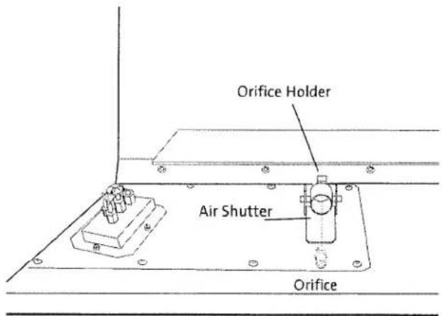
Figure 30. Burner orifice location.
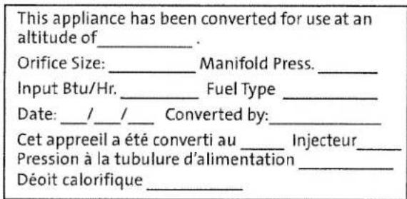
Figure 31. High Altitude Conversion Label.
6.6 Firebox Panel Installation
Brick Kits 156852 / 156853
Fieldstone Kit 156851
THE FIREBOX PANELS MUST BE INSTALLED IN THIS APPLIANCE BEFORE USE. DO NOT OPERATE THIS FIREPLACE WITHOUT FIREBOX PANELS IN PLACE.
6.6.1 With ATRA Pan Burner Log Set:
The Ceramic Burner Base (may be one-piece or three-people) must be installed before installing the firebox panels.
If you have a three-piece base (fig. 32, Sections A, B, C):
Set the two corner sections in position followed by the front section. Go to Step 5.
If you have a one-piece base:
- Remove the Burner Assembly by removing the two 10 mm hex nuts that secure it to the firebox floor. Lift the assembly up and out.
- Remove the Pilot Tray with removal of two screws.
- Locate the Burner Base that is included with the ATRA Pan Burner Log Set 156840 and set it in place on the firebox floor.
- Reinstall the Pilot Tray and Burner Assembly using the original screws and nuts. See fig. 32.
- Install the Lower Rear Panel. Push the panel all the way back, centered against the firebox wall.
- Hold the Upper Rear Panel in place with one hand while positioning one of the side panels against the firebox wall.
- Place the remaining Side Panel in position.
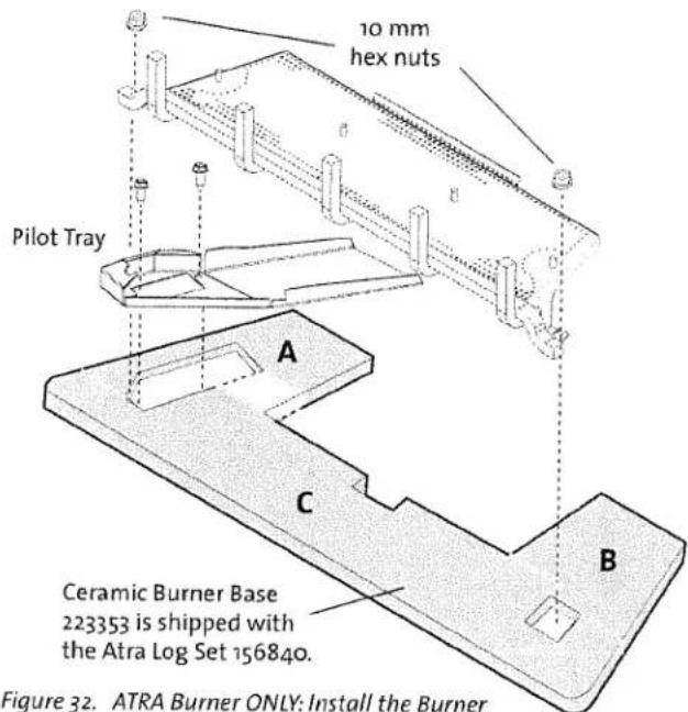
Figure 32. ATRA Burner ONLY: Install the Burner Base before installing the firebox panels.
6.6.2 With Silhouette Burner:
- Two Riser Straps are included in the Miscellaneous Hardware Kit. Break each strap into two parts at the point indicated in fig. 33.
- Form the Side and Rear Risers by bending the ends of each part at the perforations as shown in fig. 34.
- Remove the Burner Skirt by removing the two sheet metal screws at the back wall. See fig. 29, page 19. The skirt simply lifts out.
- Place the risers at the sides and rear corners of the firebox. The canted side of the Rear Riser in the left corner should face toward the front of the fireplace.
- Install the Lower Rear Panel. Push the panel all the way back and centered against the firebox wall.
- Hold the Upper Rear Panel in place with one hand while positioning one of the Left Side Panel against the firebox wall. The Side Panel will then support the Upper panel.
- Place the remaining Side Panel in position.
- Balsam Fronts - Penny Vein and Gold Vein only: Replace the black Burner Skirt Valance with the matching valance included with the front assembly. Remove three, 10 mm nuts. See #9, fig. 78, page 34.
- Replace the Burner Skirt and secure with screws.
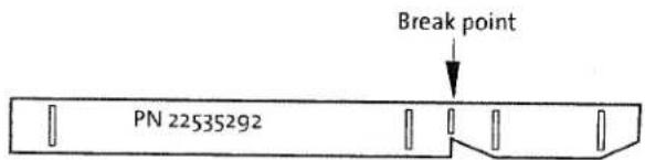
Figure 33. Panel Riser formation.
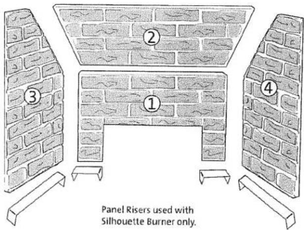
Figure 34. Install panels in the order as numbered.
6.7 Install Burner Media
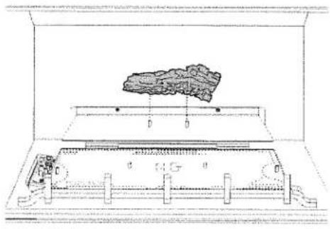
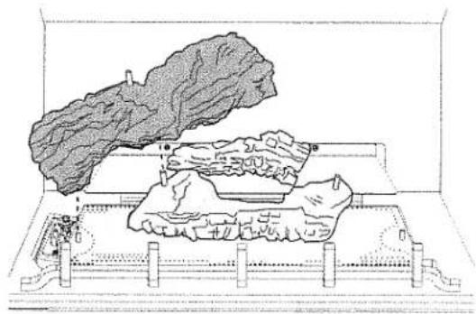
6.7.1 ATRA Log Set
For use with ATRA Pan Burner
Contents:
-
Ceramic Base
• Rear Log - 223738
• Left Front Log - 223733
• Burner Log - 223734
• Right Front Log - 223736
• Crossover Log - 223732
• Left Log - 223737
• Right Log - 223735
• Ember Stones, 6 oz. bag - 220702 -
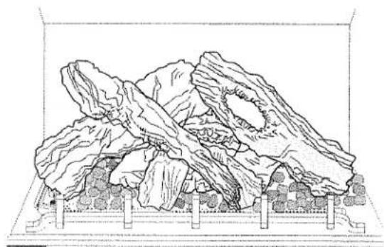
Use work gloves and handle the individual logs carefully. Install the log set as shown in figures 34-39.
- Lightly scatter the Ember Stones in a single layer over the burner plate. DO NOT USE ALL THE EMBERS. KEEP STONES AWAY FROM THE PILOT ASSEMBLY AREA. The carry-over ports directly in front of the pilot must remain clear for proper pilot ignition.
natural_image
Technical line drawing of a mechanical assembly with no visible text or symbols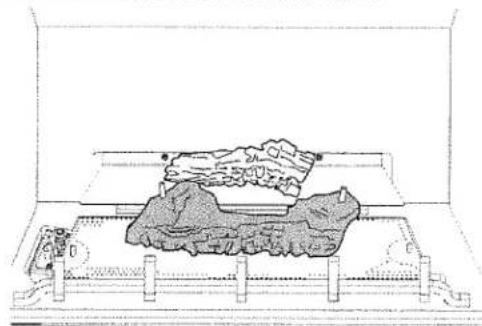
natural_image
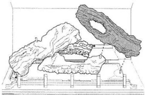
Line drawing of a geological or material sample embedded in a rectangular opening, showing layered rock formation (no text or symbols)Figure 34. Engage the Rear and Burner Logs with the pins in the rear shelf and burner plate.
natural_image
Diagram of a biological specimen with a large irregular structure inside a container, showing internal tissue and structural components (no text or labels)Figure 35. Engage the Left Log with the pins in the burner pan and Burner Log.
natural_image
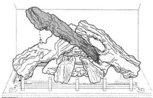
Architectural line drawing of a building facade with mountainous terrain and a large circular structure (no text or symbols)Figure 36. Engage the Right Log with the pin in the burner pan and the other pin in the Burner Log.
natural_image
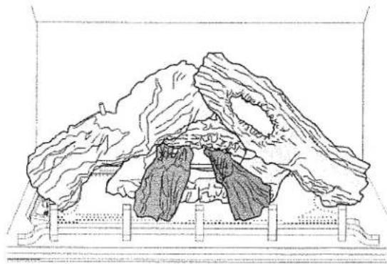
Line drawing of a mountainous landscape with layered rock formations and a central tree (no text or symbols)Figure 37. Lean the two short Front Log pieces against the Base Log.
natural_image
Line drawing of a mountainous landscape with layered rock formations and a central tree (no text or symbols)Figure 38. Engage the Crossover Log with the pin the the Left Log and rest the lower end against the short log.
natural_image
Line drawing of a cage with lettuce and leafy greens inside a container (no text or symbols)Figure 39. Evenly scatter Ember Stones in a single layer over the burner plate.
6.7.2 Beach Fire Log Set 156854
For use with Silhouette Burner
Contents:
- Base Board - 223757 - Logs, 8 - Rocks, 12
NOTE: If you are using a Penny or Gold Vein Balsam surround, do not install this burner treatment until after you have installed the matching color Burner Valance from the surround kit. The burner skirt must be removed from the fireplace to install the valance. See instructions in the surround kit.
CAUTION: THE LOGS ARE FRAGILE! HANDLE EACH PIECE CAREFULLY.
- Place the base board on the burner skirt.
- The the underside of each Rock is numbered 1-10. Set the rocks in the pockets of the Base Board in the sequence shown in fig. 40.
- Each log is also numbered, 1-8. Arrange them in the positions shown in figs. 41-a, b, and c.
- If desired, lightly scatter the Ember Stones in a single layer over the burner plate. DO NOT USE ALL THE EMBERS. KEEP STONES AWAY FROM THE PILOT ASSEMBLY AREA. The carry-over ports directly in front of the pilot must remain clear for proper pilot ignition.
Figure 40. Beach Fire Rock layout.
Figure 41-a. Beach Fire Log placement.
Figure 41-b. Beach Fire Log placement.
Figure 41-c. Beach Fire Log placement.
6.7.3 Forest Floor Sculpture 156860
For use with Silhouette Burner
Contents:
• Ceramic Base - 223758 • Left Antler - 223759
• Small Pine Cones, 8 - 223762 • Right Antler - 223760
• Large Pine Cones, 5 - 223761
NOTE: If you are using a Penny or Gold Vein Balsam surround, do not install this burner treatment until after you have installed the matching color Burner Valance from the surround kit. The burner skirt must be removed from the fireplace to install the valance. See instructions in the surround kit.
CAUTION:
THE ANTLERS ARE FRAGILE! SUPPORT THE EACH PIECE WITH BOTH HANDS AND HANDLE CAREFULLY!
- Place the base board on the burner skirt.
- Arrange the large and small pine cones on the base board as shown in fig. 42.
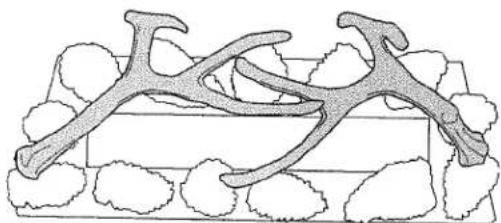
- Place the right and left antlers over the pine cones as indicated in fig. 43.
- If desired, lightly scatter the Ember Stones in a single layer over the burner plate. DO NOT USE ALL THE EMBERS. KEEP STONES AWAY FROM THE PILOT ASSEMBLY AREA. The carry-over ports directly in front of the pilot must remain clear for proper pilot ignition.
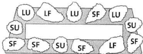
SF - Small, lay flat on side
SU - Small, stand upright
LF - Large, lay flat on side
LU - Large, stand upright
Figure 42. Recommended pine cone layout.
natural_image
Illustration of a biological structure with branching structures and surrounding cloud-like elements (no text or symbols)Figure 43. Recommended antler arrangement.
6.8 Door Assembly Ausable / Saranac / Loj Doors Placid Fronts
The steel door frame attaches to the fireplace cabinet at five points: Four frame clevises (A) engage with screws at the cabinet sides and one lower clevis (B) engages with a center bracket screw at the bottom of the cabinet.
The Placid Fronts attach only to the four (A) clevises. Use the instructions packed with those fronts.
- Using the 4 mm hex key provided, loosen the cabinet screws enough to enable the door frame clevises to engage behind them. See figs. 44-46.
- Open the doors and engage the frame with the screws on the cabinet.
- Tighten all screws.
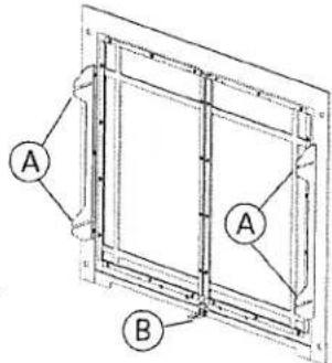
Figure 44. Door frame attachment points.
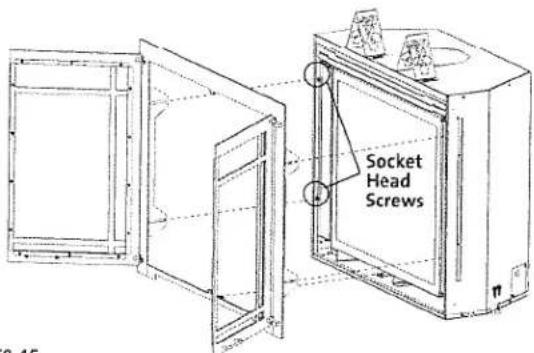
Figure 45. Door frame attachment points.
natural_image
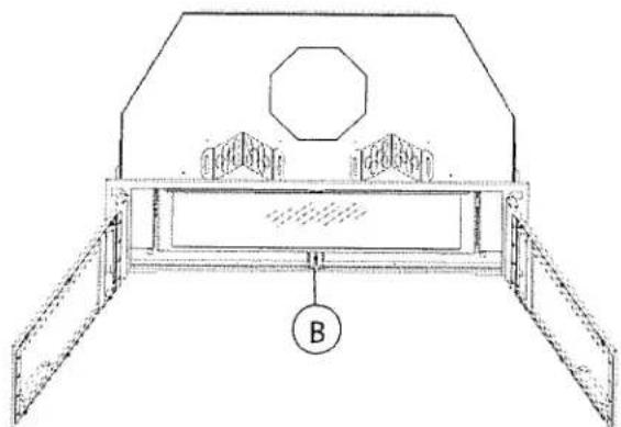
Technical line drawing of a mechanical component with a labeled part B (no text or symbols present)Figure 46. Secure panel to lower cabinet bracket, B.
6.9 Balsam Surround Assembly
The Balsam surround assembly consists of the surround panel, a clevis bracket, a hanger bracket, and either a Penny Vein or Gold Vein burner valance as appropriate.
Be sure to replace the burner valance with the color valance before assembling the Surround. See fig. 78, page 34.
Be sure that the Hanger Bracket has been installed on the cabinet as described on page 9, Fig. 9a.
- Attach the Clevis Bracket to the lower panel using the remaining two sheet metal screws. See fig. 48. Hang the surround panel on the cabinet by engaging the tabs at the upper corners over the bracket.
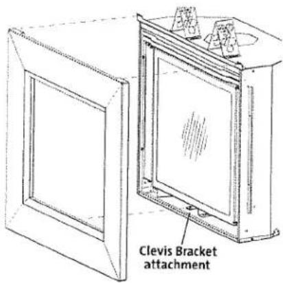
- Secure the surround panel to the bottom of the fireplace cabinet by engaging the panel clevis with the attachment bracket screw and tighten with the 4 mm hex key provided with the fireplace. See fig. 49.
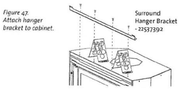
Figure 48.
Clevis bracket
assembly.
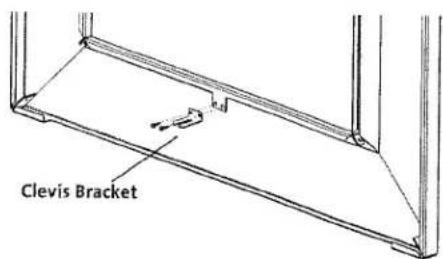
Figure 49.
Engage panel to the hanger bracket and secure to the fireplace with the button head screw at the lower clevis bracket.
6.10 Initial System Check
The burner and fan control system consists of the following built-in or supplied components:
1) Remote Transmitter - 3, AAA batteries preinstalled
2) Remote Receiver - 4, AA backup batteries preinstalled
3) Fan Control Module - switched
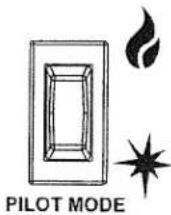
4) Pilot Mode Switch
All internal connections have been made at the factory. The remote controls are preprogrammed and the entire system tested.
NOTE: Check the build date on the shipping crate label. If it has been more than 6 months since the build date, be prepared to replace the Receiver and Transmitter batteries.
Follow this procedure for the initial system check following installation:
- Turn the Fan Control Module rocker switch to the ON position, fig. 50. It is located in the right side compartment, under the Accent Lamp control.
- Slide the Remote Receiver switch to the ON position. The ignitor will generate spark in either IPI or CPI pilot modes. See fig. 51.
- PURGING THE GAS LINE: Open the gas supply valve. When lighting the appliance for the first time it will take a few moments to clear the gas line of air. Once the purge is complete, the pilot light will ignite. Opening the inlet pressure test point will help bleed the gas line.
When purging the line, the system may go into lock-down mode. To continue purging, move the Receiver switch to OFF for 15 seconds, then switch back to REMOTE or ON and try to light the pilot again.
- PILOT FLAME: The pilot flame should be steady - not lifting or floating. The flame should be blue in color around the pilot hood, with traces of yellow toward the outer edges. It is important that the pilot flame engulf the top 1/8" of the flame sensor. The pilot flame should project out of the pilot hood 1" from both ports extending to reach the burner plate ports. See fig. 52 . The pilot flame can be tuned by turning the adjustment screw located on the front of the valve. See fig. 28.
5. INSTALLER PLEASE NOTE:
CHECK FUNCTIONALITY. The burner, remote control and fan functions have each been tested at the factory. However, it is important to run through each function and be sure to familiarize the homeowner with the operation procedures. See the Operation section on pages 26-32. for details regarding Remote Control functions and settings.
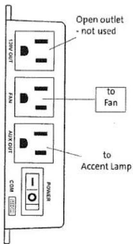
Figure 50. Fan Control Module power switch.
CPI / Continuous Pilot Ignition (Standing Pilot)
OR
IPI / Intermittent Pilot Ignition
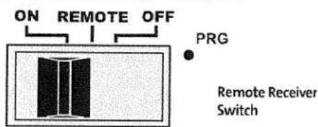
Figure 51. Initial system settings.
Figure 52. Correct Pilot flame pattern.
6.10.1 Flame Appearance / Air Shutter Adjustment
WARNING: AIR SHUTTER ADJUSTMENTS SHOULD ONLY BE PERFORMED BY A QUALIFIED, PROFESSIONAL SERVICE TECHNICIAN.
Locate the Primary Air Shutter control under the fire-box floor The shutter is set at the at the factory for the type of gas. This will give good results in the majority of installation configurations, however, you may find it necessary to adjust it to get the best flame picture depending upon the your specific installation.
To change the setting, use the Latch Tool to engage the shutter. See fig. 53. Push the shutter back toward the rear of the fireplace to decrease combustion air. Pull it forward to increase air.
Figure 53. Air Shutter adjustment.
GZ 450 DV 138978_Rev_K 6.6.13
Generally, flame appearance is a matter of individual preference, however a warm yellowish flame is most common.
■ Closing the air shutter - in extreme cases may generate very long yellow flames resulting in soot. Sooting produces black deposits on the logs, on the inside walls of the appliance, and potentially on the exterior termination cap.
Sooting is caused by incomplete combustion in the flames and lack of combustion air entering the air shutter opening.
■ Opening the air shutter - will generate a flame that is blue and transparent, or "anemic". This flame is generally more efficient, but not as attractive.
- Allow the burner to operate at the highest setting for 20-30 minutes before making any adjustments. Always make adjustments in 1/8" increments and allow the burner to settle-in for 10-15 minutes between additional adjustments.
See the Appendix section of this manual for pictorial representations of proper flame patterns for each burner type.
6.11 Operation Notes
- For the first several hours of operation, it is common to detect some odor as the metal and manufacturing materials cure under heat. This condition is temporary and can be alleviated by allowing plenty of fresh air to circulate through the area.
- Condensation may develop on the glass upon each lighting of the appliance. This "fog" will disappear as the glass heats.
- IMPORTANT: It will be necessary to clean the glass after the first few fires. A white powdery residue will be evident which results from the burner media curing. Use a non-abrasive household glass cleaner and warm water. IF THE GLASS IS NOT CLEANED, THIS RESIDUE CAN CAUSE THE GLASS TO BECOME PERMANENTLY ETCHED. DO NOT USE AMMONIA-BASED CLEANERS.
- Keep the control compartments and area under the appliance free of dust. Always keep the appliance area clear and free from combustible materials, gasoline and other flammable liquids.
- This appliance can be operated with a continuously burning pilot flame. Exercise caution when using household products containing combustible vapors.
- CAUTION: DO NOT OPERATE THIS APPLIANCE WITH THE GLASS REMOVED, CRACKED OR BROKEN. REPLACEMENT OF THE GLASS SHOULD BE DONE BY A LICENSED OR QUALIFIED SERVICE PERSON. USE ONLY REPLACEMENT GLASS PROVIDED BY YOUR AUTHORIZED ATRA DEALER. NEVER USE ANY SUBSTITUTE MATERIALS.
7.0 Operation
7.1 Features Overview
The Proflame GTMFS system is a modular remote control system that directs the functions of the Atra GZ 450 gas freestanding unit. It is configured to control the on/off operation both manually and thermostatically, with standard and "Smart" thermostat features. It will also control flame modulation, manual flame control, fan on/off and speed and on/off of accent lighting features.
The system is an IPI system (Intermittent Pilot Ignition) and also has a built in switch which allows you to keep the pilot lit continuously if desired (CPI - Constant Pilot Ignition). The power is provided to the FCM (Fan Control Module) using 120V electricity and has a 6volt DC battery back-up for operation during a power failure.
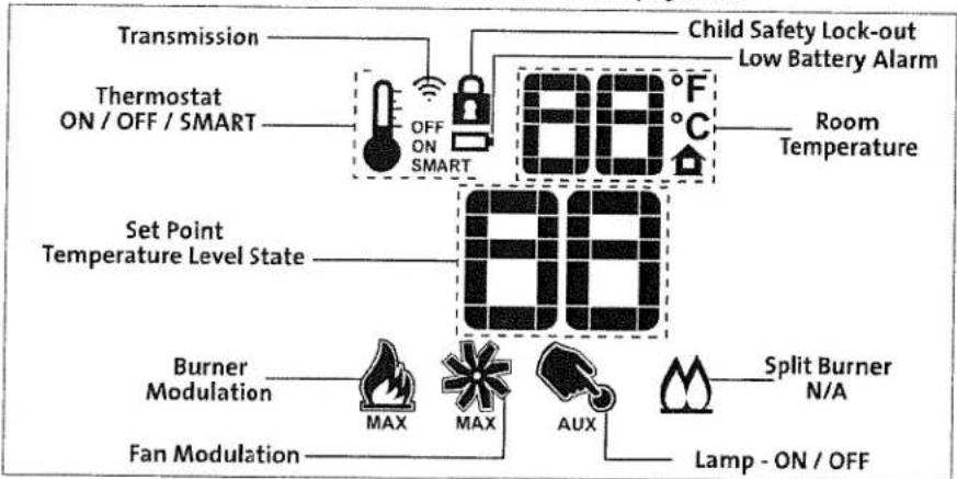
7.1.1 Remote Control Transmitter
This new remote system has all controls available on its face for reliable, ease of use. It gives room temperature readout, set temperature readout, all function abilities as well as childproof lockout and low battery indicator. Icons appear on the screen indicating which mode of operation you are controlling. The four button controls are easy to learn and simple to operate. The remote transmitter is powered by 3-1.5v AAA batteries.
7.1.2 Remote Control Receiver
The receiver is powered by 4-1.5v AA batteries. This unit has a manual on/off switch to light the burner if the remote should become inoperative.
7.1.3 Fan Control Module (FCM)
The Fan Control Module (FCM) is the electrical heart of the system. It provides power to all components, 120v ac when available, and converts to 6v DC when it is not. This powers the receiver, making the batteries in the receiver a backup power source, thus prolonging the life of the batteries. The FCM sends power to the fan system and the accent light. When no line power is available these features will not operate.
7.1.4 Digital Fireplace Control (DFC)
This is the brain of the system. The DFC allows the pilot to be set as an IPI or CPI unit. It tells the burner to light or turn off, and provides the ignitor with the electricity needed for sparking. All functional commands are routed through this part of the system and distribute the signal to the appropriate component.
7.1.5 Sit 885 Modulating Valve
This valve has the ability to be stepped down in six increments between high and low. It can be done manually or by setting the remote control to the Smart thermostat modulation mode. Automatic modulation means that as the room temperature approaches the limit set for shut down, the valve gradually decreases or "steps-down" the fire intensity. Conversely, as room temperature cools, the valve gradually increases flame intensity. The overall result is more comfortable even heating, minimizing temperature peaks and valleys.
7.1.6 Pilot Assembly
The pilot contains a pilot hood, igniter, and a sensor rod. The igniter sends a spark to the pilot hood which lights the gas. The sensor rod is then engulfed by the pilot flame, flame rectification occurs and the unit remains lit. If rectification does not occur the main burner will not light and the pilot will shut down.
WARNING:
READ AND UNDERSTAND ALL OPERATING INSTRUCTIONS BEFORE ATTEMPTING TO OPERATE THIS APPLIANCE. DO NOT ALLOW ANYONE TO OPERATE THIS APPLIANCE WHO HAS NOT READ AND UNDERSTOOD THESE INSTRUCTIONS. KEEP THE REMOTE CONTROL TRANSMITTER WHERE CHILDREN CANNOT REACH IT.
WARNING:
SEVERE INJURY. THIS APPLIANCE CAN BE SET TO OPERATE THERMOSTATICALLY. BE AWARE THAT THE FIREPLACE MAY BE VERY HOT EVEN WHEN THE BURNER IS NOT APPARENTLY OPERATING. KEEP CHILDREN AWAY FROM THE APPLIANCE.
WARNING:
OBSERVE CAUTION NEAR THE GLASS PANEL. THE GLASS MAY SHATTER IF STRUCK BY AN OBJECT. ALWAYS HANDLE THE GLASS PANEL WITH CARE.
7.2 Control Functions
7.2.1 Pilot Mode
In most cases you will want to operate the fireplace in IPI mode. This allows the most efficient use of gas, burning the pilot light only when the thermostat calls for the burner to ignite.
The CPI mode permits functional flexibility within a wide range of installation characteristics. The pilot flame remains lit when the burner is off. This is an advantage in those instances when a cold system maybe difficult to start in IPI mode. The pilot can be run until the system has warmed sufficiently for IPI operation. NOTE: THE IGNITOR WILL ALWAYS SPARK WHENEVER THE PILOT MODE IS SWITCHED TO CPI, REGARDLESS OF THE POSITION OF THE RECEIVER SWITCH.
7.2.2 Remote Receiver
The Remote Receiver, located in the left compartment, is powered through the Fan Control Module and AA back-up batteries. The Receiver can be set to one of three different positions. See fig. 54.
ON - this is a manual override allowing the burner to function without remote control. The ignitor will spark within 3 seconds.
REMOTE - Permits full function of all components by remote control Transmitter activity.
OFF - Disconnects communication between the transmitter and receiver. Turns off IPI functionality. Turn the Receiver to "OFF" whenever the fireplace will not be used and whenever service is performed.
7.2.3 Remote Transmitter
The Transmitter features a simple button layout and informative display screen. See figs. 55-56.
ON / OFF Key - controls Burner, Fan, and Lamp functions.
THERMOSTAT Key - Used to set either Manual or Thermostatic Control and index through thermostatic functions.
UP / DOWN Arrow Key - Selects thermostat temperature range, fan speed, and flame height.
MODE Key - used to select the component to be controlled: Burner, Fan, or Lamp.
DISPLAY - graphically indicates temperature settings and status of Thermostat, Burner, Fan, and Lamp.
Figure 54. Control Panels.
Figure 55. Remote transmitter function keys.
Figure 56. Remote transmitter display data.
flowchart
graph TD
    A["Transmission"] --> B["Thermostat ON/OFF/SMART"]
    B --> C["Set Point Temperature Level State"]
    C --> D["Burner Modulation"]
    D --> E["Fan Modulation"]
    D --> F["AUX"]
    F --> G["Lamp - ON / OFF"]
    D --> H["MAX"]
    H --> I["MAX"]
    I --> J["AUX"]
    J --> K["Split Burner N/A"]
    K --> L["Lamp - ON / OFF"]
    C --> M["88°F"]
    M --> N["Room Temperature"]
    C --> O["88°F"]
    O --> P["Child Safety Lock-out Low Battery Alarm"]
Remote Transmitter Controls, cont'd.
Temperature Indication Display
■ With the transmitter in the OFF position, press the Thermostat Key and the Mode Key at the same time. The display screen will show the current room temperature cycling between Fahrenheit and Celsius indicators each time the keys are pressed simultaneously. See fig. 57.
Turn on the Burner
■ Press the ON/OFF Key on the Transmitter.
The display will show all the active icons. At the same time, the Receiver will activate the Pilot Ignitor. First the pilot will ignite, followed shortly by the burner. A single "beep" from the Receiver will confirm reception of the command.
Turn off the Burner
■ Press the ON/OFF Key. The display will show only the room temperature and icon. At the same time, the Receiver will deactivate the call for heat and the burner will shut down. Fig. 59. A single "beep" from the Receiver will confirm reception of the command.
Remote Burner Control
There are six flame levels available.
■ With the system ON, and the burner flame level at maximum, press the Down Arrow Key once to reduce the flame height by one step. Each time the Down Key is pressed, the flame will step down until the burner is finally turned off. Fig. 60.
The Up Arrow Key will increase the flame height each time it is pressed. If the U Arrow Key is pressed while the system is on but the flame is off, the flame will come on in the High position. Figs. 61-62. A single "beep" will confirm reception of the command.
Room Thermostat (Transmitter Operation)
The Remote Control can operate as a room thermostat. The thermostat can be set to a desired temperature to control the comfort level in a room.
To activate this function, press the Thermostat Key, (Fig. 40.) The display will indicate that the room thermostat is "ON" and the current Set Temperature is now displayed. Fig. 63.
To adjust the Set Temperature, press the Up or Down Arrow Keys until the desired Set Temperature is displayed. Fig. 64.
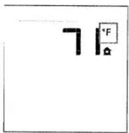
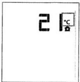
Figure 57. Room temperature readings
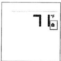
Figure 58. Burner shut-down
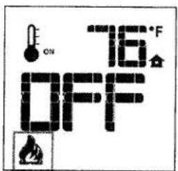
Figure 59. Burner OFF.
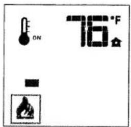
Figure 60. Flame Level 1.
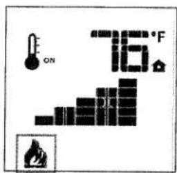
Figure 61. Flame Level 5.
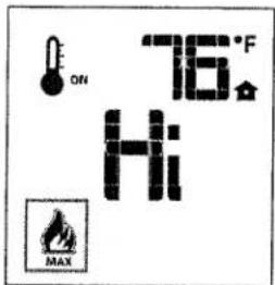
Figure 62. Flame Level 6.
Figure 63. Thermostat ON
Room Temperature
Figure 64. Change Set Temperature
SMART Thermostat Function
This function adjusts the flame intensity according to the difference in the Set Point temperature and the actual room temperature. As the room temperature gets closer to the Set Point, the Smart Function will modulate flame intensity down.
To activate this function, press the Thermostat Key until the word "SMART" appears to the right of the thermometer bulb icon. Fig. 65.
■ To adjust the temperature, press the Up or Down Arrow Keys until the desired Set Temperature is displayed. Fig. 66.
Fan Control
The fan speed can be adjusted through six settings. To activate this function, press the Mode Key (Fig. 40) to index to the Fan Control icon. See fig. 62. The fan will not function at all if it is not first set to ON.
Use the Up/Down Arrow Keys to turn ON, OFF, or adjust the fan speed. Fig. 63. A single "beep" will confirm reception of the command. After a 5 minute interval, the fan will power up to its highest speed and then modulate down to the established fan speed setting. The fan will continue to operate for 12 minutes after the burner is turned off. Manual speed control is not available when the SMART Thermostat is ON.
Accent Lamp Control (Auxiliary 120V Outlet)
The auxiliary function controls the Accent Lamp power. Press the Mode Key to index to the AUX icon. Figs. 64-65.
■ Pressing the Up Arrow Key will turn the Lamp ON. Lamp brightness can be adjusted by turning the dimmer control knob located in the right side compartment.
■ Pressing the Down Arrow Key will turn the Lamp OFF.
Child Safety Lock
This function will lockout the Transmitter to prevent unsupervised operation.
■ To activate the Lock, press the Mode key and UP Key at the same time. Fig. 66.
■ To de-activate the Lock, press the Mode Key and UP Key at the same time.
Low Battery Detection
The life-span of the batteries depends on various factors; battery quality, the frequency of ignition calls, the frequency of changes to Set Points, etc.
When Transmitter batteries are low, the Battery icon will be displayed before all battery power is lost. The icon will disappear when new batteries are installed. Fig. 67.
When Receiver batteries are low, no "beep" will be emitted from the Receiver when it receives an On/Off command from the Transmitter. This is an alert for a low battery condition in the Receiver. When the batteries are replaced, the "beep" will be emitted from the Receiver when the ON/OFF Key is pressed. See Battery
Figure 65. Smart Mode
Figure 66. Smart Set Temp.
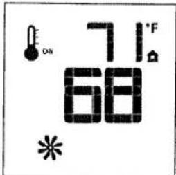
Figure 62. Fan Mode
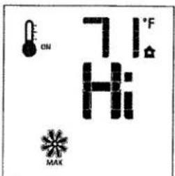
Figure 63. Fan Speed
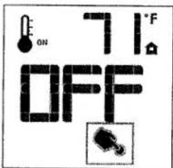
Figure 64. Lamp Control
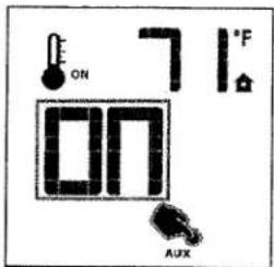
Figure 65. Lamp ON
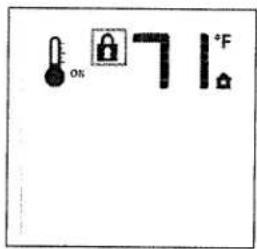
Figure 66. Lock ON
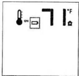
Figure 67. Low Battery
Replacement under the Maintenance section of this manual.
Manual By-Pass of the Remote System
When battery power is low or depleted, the burner can still be operated manually by sliding the Receiver switch to the ON position. It will immediately ignite in the High position. In manual mode, the unit has a 24 hour operating cycle. It will automatically shut down after 24 hours of operation and then require a manual restart.
In the event of a power failure, fan and lamp functions will be unavailable. Battery back-up will allow flame modulation and thermostatic control. It is therefore advisable to keep a supply of good quality batteries on hand.
flowchart
graph TD
    A["CPI / IPI SWITCH"] --> B["FAN CONTROL MODULE"]
    B --> C["POWER"]
    C --> D["PROFLAME VALVE ELECTRONIC MODULATION"]
    D --> E["PROFLAME DIGITAL FIREPLACE BURNER CONTROL"]
    E --> F["E1 PILOT ASSEMBLY"]
    F --> G["PILOT GROUND WIRE"]
    G --> H["SPARK GROUND"]
    H --> I["PILOT SENSOR"]
    I --> J["PILOT GROUND WIRE"]
    J --> K["PILOT GROUND WIRE"]
    K --> L["PILOT GROUND WIRE"]
    L --> M["PILOT GROUND WIRE"]
    M --> N["PILOT GROUND WIRE"]
    N --> O["PILOT GROUND WIRE"]
    O --> P["PILOT GROUND WIRE"]
    P --> Q["PILOT GROUND WIRE"]
    Q --> R["PILOT GROUND WIRE"]
    R --> S["PILOT GROUND WIRE"]
    S --> T["PILOT GROUND WIRE"]
    T --> U["PILOT GROUND WIRE"]
    U --> V["PILOT GROUND WIRE"]
    V --> W["PILOT GROUND WIRE"]
    W --> X["PILOT GROUND WIRE"]
    X --> Y["PILOT GROUND WIRE"]
    Y --> Z["PILOT GROUND WIRE"]
    Z --> AA["PILOT GROUND WIRE"]
    AA --> AB["PILOT GROUND WIRE"]
    AB --> AC["PILOT GROUND WIRE"]
    AC --> AD["PILOT GROUND WIRE"]
    AD --> AE["PILOT GROUND WIRE"]
    AE --> AF["PILOT GROUND WIRE"]
    AF --> AG["PILOT GROUND WIRE"]
    AG --> AH["PILOT GROUND WIRE"]
    AH --> AI["PILOT GROUND WIRE"]
    AI --> AJ["PILOT GROUND WIRE"]
    AJ --> AK["PILOT GROUND WIRE"]
    AK --> AL["PILOT GROUND WIRE"]
    AL --> AM["PILOT GROUND WIRE"]
    AM --> AN["PILOT GROUND WIRE"]
    AN --> AO["PILOT GROUND WIRE"]
    AO --> AP["PILOT GROUND WIRE"]
    AP --> AQ["PILOT GROUND WIRE"]
    AQ --> AR["PILOT GROUND WIRE"]
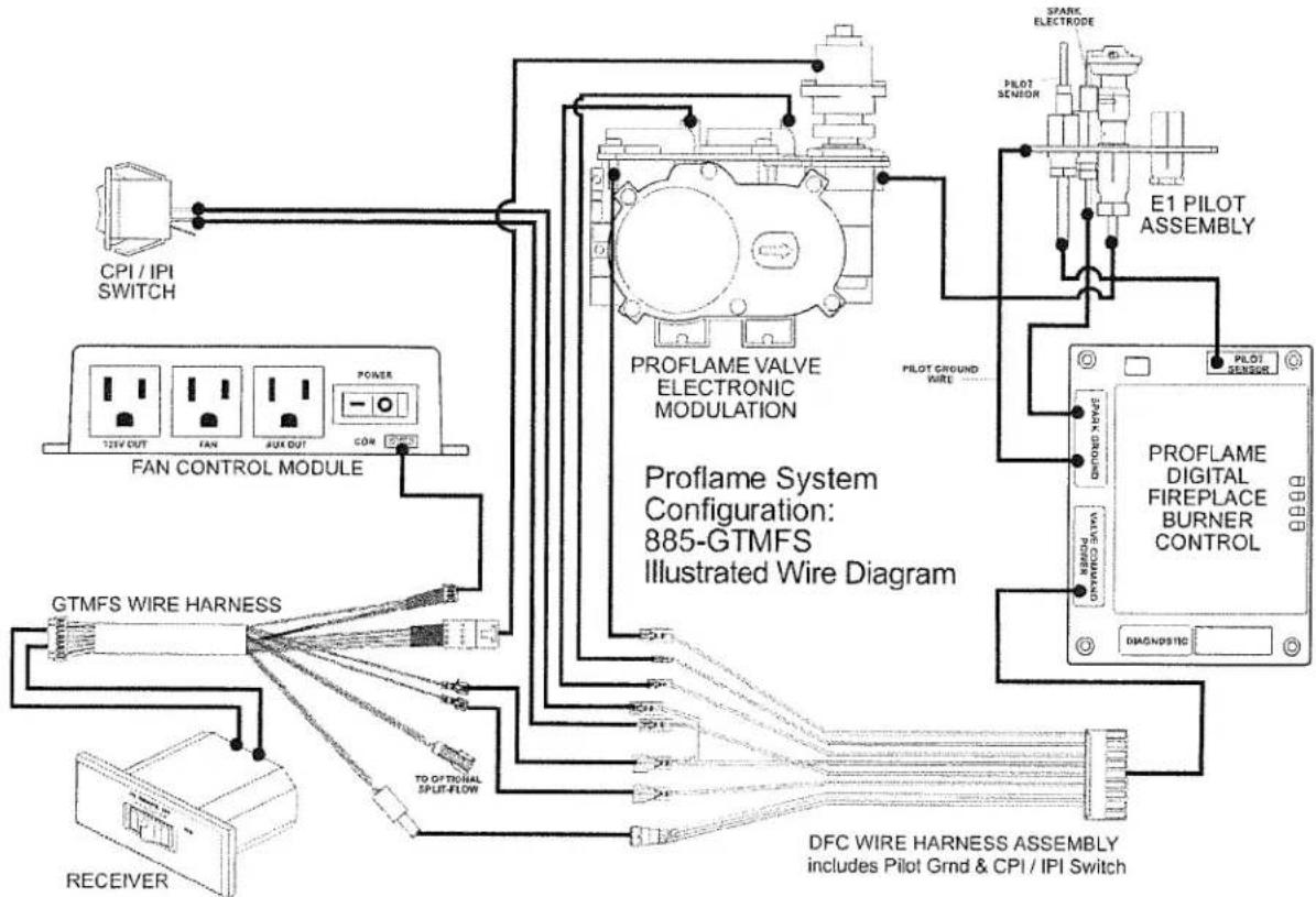
Figure 68. Wiring schematic, SIT Proflame 885 Burner Control System
Technical Data
Fan Control Module
Supply voltage/frequency: 120V, 60 Hz
Ambient temp. ratings: 32 to 140° F
Three wire bus: -Two wires provide DC voltage to the Receiver
- One wire gives uni-directional signal from the Receiver
Output voltage/frequency/current: 120V / 60 Hz / 5 A
Auxiliary switched output: 120V / 60 Hz / 2 A
Fan speed output: 120V / 60 Hz / 1A
Remote Control Transmitter
Supply voltage: 4.5 V (three 1.5V AAA batteries)
Ambient temp. rating: 32 to 122° F
Radio frequency: 315 MHz
Receiver:
Supply voltage 6.0 V (four 1.5 AA batteries)
Ambient temp. rating: 32 to 140° F
Radio frequency: 315 MHz
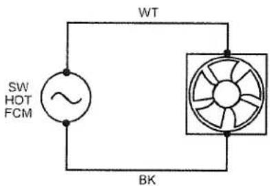
Figure 69. Wiring Diagram - GZ 450 DV Blower
CAUTION: LABEL ALL WIRES PRIOR TO DISCONNECTION WHEN SERVICING THE CONTROLS. WIRING ERRORS CAN CAUSE IMPROPER AND DANGEROUS OPERATION. ALWAYS VERIFY PROPER OPERATION AFTER SERVICING THE APPLIANCE.
ATTENTION: AU MOMENT DE L'ENTRETIENDES COMMANDES, ÉTIQUETEZ TOUS LES FILS AVANT LE DÉBRANCHEMENT. DES ERREURS DE CÂBLAGE PEUVENT ENTRAÎUN FONCTIONNEMENT INADÉ- QUAT ET DANGEREUX.
8.0 Maintenance
This appliance and its venting system should be inspected before use and at least annually by a qualified service technician.
WARNING!
THE IGNITION SYSTEM OF THIS APPLIANCE CARRIES LIVE VOLTAGE. ALWAYS TURN "OFF" THE MAIN GAS SUPPLY AND DISCONNECT THE POWER SOURCE BEFORE PERFORMING ANY MAINTENANCE PROCEDURE.
TURN "OFF" THE MAIN GAS SUPPLY AND DISCONNECT THE POWER SUPPLY TO THE APPLIANCE BEFORE REPLACING BATTERIES.
8.1 Annual Cleaning
8.1.1 Vent System
The entire vent system should be inspected and cleaned every year. If the intake and exhaust venting is disassembled for any reason, it should be reassembled and sealed according to the vent manufacturer's instructions provided at the initial installation.
8.1.2 Burner and Log Set
Periodically inspect the firebox and valve compartment to BE CERTAIN THAT THE FLOW OF COMBUSTION AND VENTILATION AIR IS UNOBSTRUCTED.
The firebox should be vacuumed at least annually to remove any surface build up. Use a soft brush attachment and handle the logs carefully as they are fragile.
8.2 Glass Care
Clean the glass as necessary. Wipe the surface with a clean, dampened, soft cloth. Follow with a dry, soft towel. Take care not to scratch the glass surface.
WARNING: DO NOT USE ABRASIVE OR AMMONIA-BASED CLEANERS AS THESE WILL ETCH THE GLASS. NEVER CLEAN THE GLASS WHEN IT IS HOT.
8.3 Gasket Inspection
It is important that the glass gasket be inspected at least annually. Examine the ribbon gasket for signs of deterioration and make sure the gasket has a positive seal. Replace the gasket if necessary.
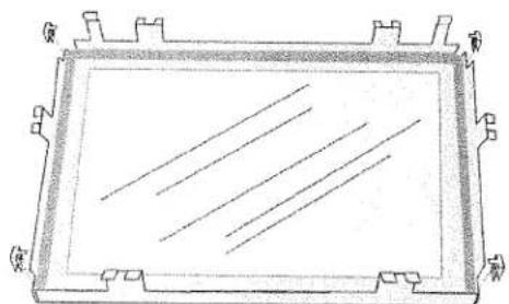
FOR REPLACEMENT, USE ONLY CERAMIC GLASS PANEL KIT 156817. DO NOT USE ANY OTHER TYPE OF GLASS WITH THIS APPLIANCE.
8.4 Glass & Gasket Replacement
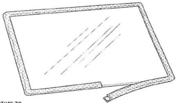
- Using the Latch Tool, disengage the 6 latches from the glass frame and lift the frame up and off of the firebox.
- Lay the assembly upside down on a flat surface, protecting the frame from scratches using a blanket or towel.
- The glass panel is held in place by four retainer tabs, one at each corner. Use a screwdriver or needle nose pliers to carefully pry these up to release the glass. If the tabs break off, use the Tinnerman clips supplied with the replacement glass kit to secure the glass panel within the frame.
- Remove the old gasket material.
- Beginning at the midpoint of the lower edge, apply the new gasket around the glass panel, with the adhesive side inside and the thicker portion on the outside. DO NOT STRETCH THE GASKET MATERIAL. Trim off any excess, leaving a 1/2" overlap as shown in fig. 70.
- Lay the glass panel within the glass frame and press the tabs back down or press the clips in place as shown in fig. 71.
natural_image
Line drawing of a rectangular electronic device with a handle and screen (no text or symbols)Figure 70. Gasket application, PN 129124
natural_image
Technical line drawing of a rectangular frame with internal diagonal lines and corner brackets (no text or symbols)Figure 71. 156817 Glass Replacement Kit includes gasket and spare retainer clips.
8.5 Battery Replacement
Battery life depends on many variables; the quality of the batteries, frequency of remote use, and mode of pilot operation. Keep a supply of good quality batteries on hand to be assured of functional continuity in the event of a power failure.
The Remote Transmitter batteries are easily accessed through the tabbed cover plate. Be sure to orient the batteries for correct polarity as indicated in the battery compartment.
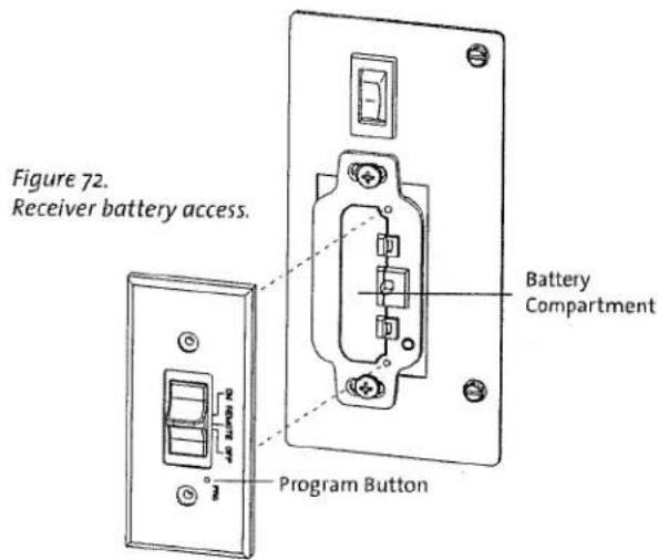
8.5.1 Receiver Battery Replacement
It will be necessary to remove the left side compartment door to access the battery cover plate.
- Remove the lower door hinge bracket (one, 10 mm nut). The door will drop out of the upper hinge bracket.
- Push the slider switch into the OFF position. Remove the Receiver cover plate screws and pry the cover plate with slider switch off of the battery box. See fig. 72.
- Install 4 AA batteries into the receiver bay. Note the polarity of the batteries and insert into the battery bay as indicated on the bay cover (+/-).
- With the switch still in the OFF position, align the slider switch with the switch stem and snap the cover plate back onto the battery box.
- Replace the Receiver cover plate screws.
- Replace the Compartment Door and lower hinge bracket.
8.5.2 Initializing the Remote Control
Each time you replace the batteries, you may need to initialize communication between the Receiver and the Transmitter.
- Place the slider switch in the REMOTE position.
- Insert the end of a paper clip into the hole marked PRG on the Receiver cover. The Receiver will "beep" three (3) times to indicate that it is ready to synchronize with the Transmitter.
- Install 3, AAA batteries in the Transmitter bay and push the ON button. The Receiver will "beep" four times to indicate the Transmitter's command is accepted and sets to the particular code of that Transmitter. The system is now initialized.
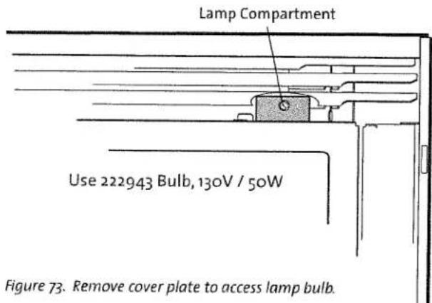
8.6 Accent Lamp Replacement
Handle the replacement bulb with gloves. Skin oils will cause the bulb to fail prematurely. If you touch the bulb with your bare fingers, wipe it clean with a soft cloth.
- Remove lamp compartment cover plate. See fig. 73.
- Remove the two phillips screws from the bulb socket to access the bulb. Pull the bulb out of the housing.
- Plug the new bulb into the socket and re-install the cover plate into the lamp housing.
9.0 Atra GZ 450 DV Replacement Parts
Use only genuine Atra Replacement Parts available from your local Authorized Jøtul Dealer or by contacting:
Jøtul North America
55 Hutcherson Dr.
Gorham, ME 04038
207 591-6601
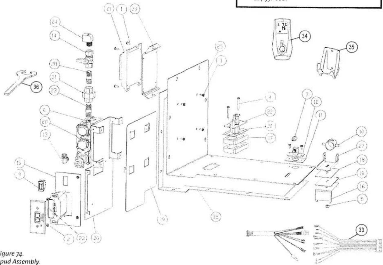
Figure 74. Spud Assembly.
| No. | Part Number | Description |
| 1 | 117917 | Screw, HWH SMA 8 x 1/2 SL Blk Oxide |
| 2 | 117967 | Screw, Pan Head #7 x 3/8 PH SMA Zinc |
| 4 | 118218 | Screw, #8 X 3/4 SL HWH SMA ZINC |
| 5 | 118016 | Nut, Lock M6 DIN 98ov Stover Zinc |
| 6 | 118214 | Screw, #8 X 3/8", Taptite, SLHWH, SZPL |
| 7 | 129130 | Orifice, Burner - #38 / NG |
| 045025 | Orifice, Burner - #52 / LP | |
| 9 | 120517 | Switch, Rocker, SPST, Black, Plain |
| 10 | 221390 | Primary Air Shutter Assembly |
| 11 | 222280 | Gasket, Drop In Orifice Holder |
| 12 | 222291 | Orifice Holder, Drop In Assembly |
| 13 | 222292 | Elbow, 90°, Brass 3/8 NTP X 3/8" Dia. Tube |
| 14 | 222407 | Valve, Straight 3/8 FIP X 3/8 FIP |
| 15 | 223329 | Burner Control Face Plate, Silkscreened |
| 16 | 222714 | Handle Outer, Primary Air |
| 17 | 225345 | Spacer, Pilot |
| 18 | 222911 | Gasket, Pilot Spacer |
| 19 | 222913 | Heat Shield, Valve |
| 20 | 157410 | Proflame Valve w/Stepper Motor, NG |
| 157411 | Proflame Valve w/Stepper Motor, LP | |
| 21 | 222924 | Proflame IPI Ignition Board |
| No. | Part Number | Description |
| 22 | 224785 | Pilot Assembly, PSE Integrated Dual-fuel |
| 23 | 222928 | Proflame S Receiver |
| 24 | 222941 | Elbow, Brass, Street, 90°, 3/8 NTP |
| 25 | 222971 | Spud Plate |
| 26 | 222972 | Bracket, Valve |
| 27 | 222973 | Inner Handle, Primary Air |
| 28 | 223214 | 3/8" x 1 1/2" Black Iron Nipple |
| 29 | 223244 | Bracket, IPI Ignition Board |
| 30 | 129670 | Gasket, Pilot Assembly |
| 31 | 223321 | 3/8" Black Iron Union |
| 32 | 225344 | Gasket, Spud Plate |
| 33 | 157024 | Proflame Wire Harness |
| 34 | 222926 | Proflame GTMFS Transmitter |
| 35 | 223951 | Remote Transmitter Wall Bracket |
| 36 | 223808 | Union Wrench |
| 37 | 222943 | Light Bulb, 130V / 50W* |
| 38 | 222942 | Light Bulb Fixture, High Temp* |
| 39 | 222974 | Glass Panel, Light Bulb Compartment* |
* not illustrated
GZ 450 DV 138978_Rev_K 6.6.13
| No. | Part Number | Description |
| 1 | 117917 | Screw, HWH SMA 8 x 1/2 SL Blk Oxide |
| 2 | 220709 | Knob, Rheostat Control |
| 3 | 220700 | Rheostat, Short Lead |
| 4 | 222916 | Bracket, Lower FCM Mount |
| 5 | 222917 | Bracket, Upper FCM Mount |
| 6 | 222918 | Heat Shield, FCM |
| 7 | 157026 | Proflame Fan Control Module |
| 8 | 223328 | Dimmer Control Face Plate, Silkscreened, GZ 450/650 |
Figure 76.
Glass Frame Assembly
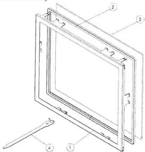
| No. | Part Number | Description |
| 1 | 22270392 | Glass Frame, GZ450 (Painted Black) |
| 2 | 129124 | 9' Gasket, Fiber Glass w/ Graphite, .25 X 138 Nominal |
| 3 & 2 | 157025 | Replacement Glass Kit, inc. gasket |
| 4 | 223307 | Latch Release Tool |
| Front Components not illustrated | ||
| 5 | 22533292 | Bottom Surround Support Bracket |
| 6 | 222745 | Control Door Bracket, Upper & Lower |
| 7 | 22275992 | Control Door |
| 8 | 157027 | Door Latch Assembly |
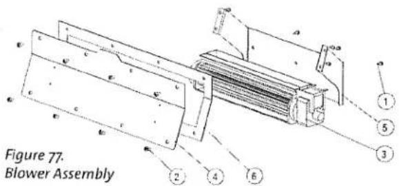
| No. | Part Number | Description |
| 1 | 117917 | Screw, HWH SMA 8 x 1/2 SL Blk Oxide |
| 2 | 117978 | Screw, Button Head Socket M6X10 Blk |
| 3 | 222072 | Blower, TransFlow, 12" Cage, 120 CFM |
| 4 | 222708 | Blower Access Panel, GZ 450 DV |
| 5 | 222970 | Bracket, Blower Mount, GZ 450 DV |
| 6 | 225334 | Gasket, Blower Access Panel |
| No. | Part Number | Description |
| 1 | 156863 | Burner Assembly, Atra Logset Grate, NG |
| 2 | 156864 | Burner Assembly, Atra Logset Grate, LP |
| 3 | 225399 | Air Deflector |
| 4 | 22296692 | Burner Skirt, Rear, Atra Logset |
| 5 | 223353 | Ceramic Base, Atra Logset |
| 6 | 156865 | Burner Assembly, Silhouette |
| 7 | 22535192 | Burner Skirt, Silhouette Burner |
| 8 | 22535292 | Firebox Panel Riser, assembled to 4 pieces |
| 9 | 22333992 | Valence, Burner Skirt / Black |
| 157006 | Valence, Burner Skirt / Penny Vein - Balsam only | |
| 157007 | Valence, Burner Skirt / Gold Vein - Balsam only | |
| 10 | 22412692 | Pilot Tray |
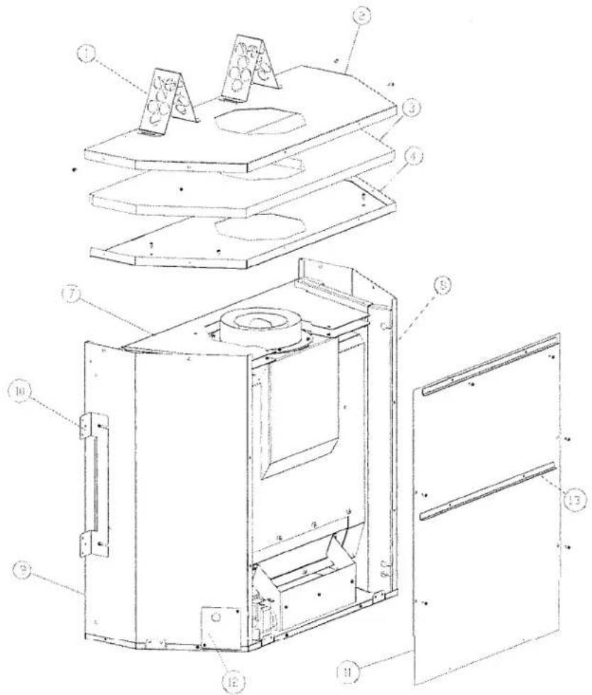
Figure 79. Fireplace Cabinet Parts
| No. | Part Number | Description |
| 1 | 221360 | Top Stand-off |
| 2 | 22272092 | Outer Top Panel |
| 3 | 222967 | Top Insulation Blanket |
| 4 | 22271992 | Inner Top Panel |
| 7 | 22271292 | Inner Top Heat Shield, 2 |
| 8 | 22271692 | Left Side Cabinet Panel |
| 9 | 22271792 | Right Side Cabinet Panel |
| 10 | 223811 | Nail Bracket / Side Stand-off, 3 |
| 11 | 222718 | Rear Cabinet Panel |
| 12 | 223305 | Junction Box Cover |
| 13 | 225358 | Rear Stand-off, (2) |
10.0 Appendix
10.1 Approved Vent Manufacturers
The Atra GZ 450 DV fireplace is approved for installation with direct vent chimney components supplied by the following manufacturers:
Simpson Dura-Vent, Inc.
P.O. Box 1510
Vacaville, CA 95696-1510
800-835-4429
Selkirk Corporation
1301 W. President George Bush Hwy, Suite 330
Richardson, TX 75080-1139
800-992-8368
American Metal Products (Amerivent)
8601 Hacks Cross Rd.
Olive Branch, MS 38654
800-423-4270
Security Chimneys International Limited
2125 Monterey, Laval, Québec
Canada,H7L3T6
450-973-9999
Metal-Fab, Inc.
P.O. Box 1138
Wichita, KS 67201
316-943-2351
ICC, Inc.
400 J-F Kennedy St. Jerome, Quebec
Canada, J7Y 4B7
450-565 6336
Bernard Dalsin Manufacturing (Proform)
5205 208th St W
Farmington, MN 55024
651-460-1080
10.2 Mobile Home Installation
The Atra GZ 450 DV can be installed for use in a mobile home in the U.S. and Canada provided:
- The fireplace must be secured to the floor of the mobile home. A bracket is located on each side of the fireplace through which wood screws or other appropriate fasteners should be secured to the floor.
- The fireplace is installed in accordance with Title 24 CFR, Part 3280- Manufactured Home Construction and Safety Standard, in the U.S. Comply with CSA Z240.4, Gas Equipped Recreational Vehicles and Mobile Housing, in Canada.
- Always contact your local officials about installation restrictions and requirements in your area.
THIS APPLIANCE MAY BE INSTALLED AS AN OEM INSTALLATION IN A MANUFACTURED (MOBILE) HOME AND MUST BE INSTALLED IN ACCORDANCE WITH THE MANUFACTURER'S INSTRUCTIONS AND THE MANUFACTURED HOME CONSTRUCTION AND SAFETY STANDARD, TITLE 24 CFR, PART 3280, STANDARD FOR MANUFACTURED HOME INSTALLATION, ANSI/NCBCS A255.1 OR STANDARD FOR CANADA, CSA Z240.4. THIS APPLIANCE IS ONLY FOR USE WITH THE TYPE OF GAS THAT IS INDICATED ON THE Fireplace'S RATING PLATE. THIS APPLIANCE MAY BE INSTALLED IN AN AFTERMARKET PERMANENTLY LOCATED, MANUFACTURED (MOBILE) HOME, WHERE NOT PROHIBITED BY LOCAL CODE.
CET APPAREIL PEUT ETRE INSTALLE DANS UN MAISON PREFABRIQUEE (MOBILE) DEJA INSTALLEE A DEMEURE SI LES REGLEMENTS LOCAUX LE PERMETTENT.
CET APPAREIL DOIT ETRE UTILISE UNIQUEMENT AVEC LES TYPES DE GAS INDIQUES SUR LA PLAQUE SIGNALETIQUE. NE PAS L'UTILISER AVEC D'AUTRES GAS SAUF SI UN KITDE CONVERSION CERTIFIE EST INSTALLE.
10.3 Proper Flame Pictures
natural_image
Line drawing of a fire pit with smokestacks and firecrackers (no text or symbols)Figure 79. Traditional Logs flame picture.
10.4 Wiring Diagram
Figure 82. Electrical wiring diagram. See fig. 26, hard wiring instructions on Page 17.
natural_image
Illustration of a fire pit with multiple firewood structures and wooden planks (no text or symbols)Figure 80. Beach Fire flame picture.
natural_image
Illustration of a biological or geological formation with layered structures and organic textures (no text or symbols)Figure 81. Antlers & Pine Cones flame picture.
11.0 Jøtul Group Gas Product Limited Lifetime Warranty
This warranty policy applies to gas products identified by Jøtul, Scan, and Atra trade names, as set forth below.
A. LIMITED FIVE YEAR WARRANTY - Cast Iron, Steel Doors, Surround Components, Firebox:
Jøtul North America Inc. (J∅TUL) warrants, to the original retail purchaser, that those components of the Jøtul, Scan, or Atra Gas Stove or Fireplace specified above will be free of defects in material and workmanship for a period of five (5) years from the date of purchase. This warranty is subject to the terms, exclusions and limitations set forth in the following text.
B. LIMITED TWO YEAR WARRANTY - Burner, Burner Treatments, Firebox Panels:
J∅TUL warrants, to the original retail purchaser, that those components of the Jøtul, Scan, or Atra Gas Stove or Fireplace specified above will be free of defects in material and workmanship for a period of two (2) years from the date of purchase. This warranty is subject to the terms, exclusions, and limitations set forth in the following text.
C. LIMITED TWO YEAR WARRANTY - Enamel Finish:
J∅TUL warrants, to the original retail purchaser, the enamel finish on cast iron components of the Jøtul Stove or Fireplace Insert specified above against peeling or fading for a period of two (2) years from the date of purchase. This warranty is subject to the terms, exclusions and limitations set forth below.
D. LIMITED ONE YEAR WARRANTY - Gas & Electrical Components (controls, plumbing, valve, blower):
J∅TUL warrants, to the original retail purchaser, that those components of the Jøtul, Scan, or Atra Gas Stove or Fireplace specified above will be free of defects in material and workmanship for a period of one (1) year from the date of purchase. This warranty is subject to the terms, exclusions, and limitations set forth in the following text.
J∅TUL will repair or replace (including parts & labor), at its option, any of the above components determined by J∅TUL to be covered by this warranty. You must, at your own expense, arrange to deliver or ship the component to an authorized Jøtul, Scan, or Atra dealer and arrange for pickup or delivery of the component after repairs have been made. If, upon inspection, J∅TUL determines that the component is covered by this warranty, the repair or replacement will be made as set forth above. This warranty is not transferable and is extended only to, and is solely for the benefit of, the original retail purchaser of the Jøtul, Scan, or Atra Gas Stove or Fireplace. This paragraph sets forth the sole remedy available under this warranty in the event of any defect in the Jøtul, Scan, or Atra Gas Stove or Fireplace.
The warranty period for any replaced component will be the remaining unexpired portion of the warranty period for the original component.
Please retain your dated sales receipt in your records as proof of purchase.
EXCLUSIONS AND LIMITATIONS
NOTICE: This warranty is void if installation or service is performed by someone other than an authorized installer, service agency or gas supplier, or if installation is not in conformance with the installation and operating instructions contained in this owner's manual or local and/or national fire and building regulations. A listing of local authorized installers, service agencies and gas suppliers can be obtained from the National Fireplace Institute at http://www.nficertified.org/.
This warranty does not cover the following:
1) Repair or replacement of parts that are subject to normal wear and tear during the warranty period or to parts that may require replacement in connection with normal maintenance. These parts include gaskets and glass (except to the extent such parts suffer damage from thermal stress).
2) Damage due to incorrect installations not in conformance with the installation instructions contained in this owner's manual or local and/or national fire and building regulations.
3) Damage due to service performed by an installer, service agency or gas supplier, unless otherwise agreed to in writing by J∅TUL.
4) Labor or other costs associated with the repair of gas controls, Plumbing, burners, log set, or sheet metal firebox beyond the warranty period.
5) Damage caused by unauthorized modification, use or repair.
6) Damage to enameled surfaces caused by improper operation or misuse, including use that is not in conformance with the operating instructions contained in this owner's manual. Such damage can typically be identified by bubbling, cracking, or discoloration of the enamel finish.
7) Costs incurred by travel time and/or loss of service.
8) Damage incurred while the Jøtul, Scan, or Atra Gas Stove or Fireplace is in transit.
IN NO EVENT SHALL J∅TUL, ITS PARENT COMPANY, SHAREHOLDERS, AFFILIATES, OFFICERS, EMPLOYEES, AGENTS OR REPRESENTATIVES BE LIABLE OR RESPONSIBLE TO YOU FOR ANY SPECIAL, INDIRECT, INCIDENTAL, CONSEQUENTIAL, PUNITIVE OR OTHER SIMILAR DAMAGES, INCLUDING, BUT NOT LIMITED TO, LOST PROFITS, LOST SALES, INJURY TO PERSON OR PROPERTY, OR DAMAGES TO A STRUCTURE OR ITS CONTENTS, ARISING UNDER ANY THEORY OF LAW WHATSOEVER. ALL IMPLIED WARRANTIES, INCLUDING THE IMPLIED WARRANTIES OF MERCHANTABILITY AND FITNESS FOR A PARTICULAR PURPOSE, OR OTHERWISE, ARE LIMITED IN DURATION TO THE LENGTH OF THIS WRITTEN WARRANTY. EXCEPT AS EXPRESSLY SET FORTH HEREIN, J∅TUL MAKES NO ORAL, WRITTEN OR OTHER WARRANTY WITH RESPECT TO J∅TUL, SCAN OR ATRA GAS STOVES OR FIREPLACES.
Some states do not allow the exclusion or limitation of incidental or consequential damages, or limitations on the length of implied warranties. Therefore, the above exclusions or limitations may not apply to you. This warranty gives you specific legal rights, and you may have other rights, which vary from state to state.
J∅TUL reserves the right to discontinue, modify or change the materials used to produce the Jøtul, Scan, or Atra Gas Stove or Fireplace. J∅TUL shall have the right to replace any defective component with substitute components determined by J∅TUL to be of substantially equal quality and price.
The dollar value of J∅TUL's liability for breach of this warranty shall be limited exclusively to the cost of furnishing a replacement component. J∅TUL shall not in any event be liable for the cost of labor expended by others in connection with any defective component. Any costs or expenses beyond those expressly assumed by J∅TUL under the terms of this warranty shall be the sole responsibility of the owner(s) of the Jøtul, Scan, or Atra Gas Stove or Fireplace.
No dealer, distributor, or other person is authorized to modify, augment, or extend this limited warranty on behalf of J∅TUL. NO MODIFICATION OR CHANGE TO THIS WARRANTY WILL BE EFFECTIVE UNLESS IT IS MADE IN A WRITTEN DOCUMENT MANUALLY SIGNED BY AN AUTHORIZED OFFICER OF J∅TUL.
An authorized installer may have been provided with certain information related particularly to the Jøtul, Scan, or Atra Gas Stove or Fireplace; however, no authorized installer or other person who may service the appliance is an agent of J∅TUL. No inference should be made that J∅TUL has tested, certified, or otherwise pronounced any person as qualified to install or service the appliance. J∅TUL shall not be liable or otherwise responsible for any error or omission by a person installing or servicing a Jøtul, Scan, or Atra Gas Stove or Fireplace.
If you believe your Jøtul, Scan, or Atra Gas Stove or Fireplace is defective, you should contact your nearest authorized Jøtul, Scan, or Atra dealer, who will process a warranty claim. IN ORDER TO QUALIFY FOR WARRANTY COVERAGE, J∅TUL MUST RECEIVE NOTICE OF A POSSIBLE DEFECT WITHIN SIXTY (60) DAYS OF THE DATE THE DEFECT IS FIRST DISCOVERED, OR REASONABLY COULD HAVE BEEN DISCOVERED.
This warranty is given by Jøtul North America, Inc., 55 Hutcherson Drive, Gorham, Maine 04038 USA
LIGHTING INSTRUCTIONS
FOR YOUR SAFETY, READ BEFORE LIGHTING.
WARNING:
IF YOU DO NOT FOLLOW THESE INSTRUCTIONS EXACTLY, A FIRE OR EXPLOSION MAY RESULT CAUSING PROPERTY DAMAGE, PERSONAL INJURY, OR LOSS OF LIFE.
A. This appliance is equipped with an ignition device which automatically lights the pilot. Do not try to light the pilot by hand.
B. BEFORE LIGHTING, smell all around the appliance area for gas. Be sure to smell next to the floor because some gas is heavier than air and will settle to the floor.
WHAT TO DO IF YOU SMELL GAS:
• Extinguish any open flame.
- Open windows.
• Do not light any appliance.
• Do not touch any electrical switches.
• Do not use any phone in your building.
- Immediately call your gas supplier from a neighbor's phone.
- If your gas supplier cannot be reached, call the fire department.
C. Use only your hand to push in or turn the gas control knob. Never use tools. If the knob will not push in or turn by hand, do not try to repair it. Call a qualified technician. Force or attempted repair may result in a fire or explosion.
D. Do not use this appliance if any part has been under water. Immediately call a qualified service technician to inspect the appliance and to replace any part of the control system and any gas control which has been under water.
LIGHTING INSTRUCTIONS
- STOP! Read the safety information above.
- Set the thermostat to the lowest setting.
- Set the Mode Control Switch to the "OFF" position.
- This appliance is equipped with an ignition device which automatically lights the pilot. Do not try to light the pilot by hand.
REMOTE RECEIVER MODE CONTROL SWITCH
- Wait five (5) minutes to clear out any gas. Then, smell for gas, including near the floor. If you smell gas, STOP! Follow "B" in the safety information above on this label. If you do not smell gas, go to the next step.
-
Set the Mode Control Switch to the "ON" position. The pilot will light.
-
Set the Mode Control Switch to the "RFMOTE" position.
natural_image
Simple line drawing of a person sitting at a desk with papers and papers, no text or symbols presentPILOT LIGHT ASSEMBLY
- Set the thermostat to the desired setting to light the burner. If the appliance will not operate, follow the instructions" To Turn Off Gas To Appliance", and call your service technician or gas supplier.
TO TURN OFF GAS TO THE APPLIANCE:
- Set the thermostat to the lowest setting.
-
Turn off all electrical power to the appliance if service is to be performed.
-
Set the Mode Control Switch to the "OFF" position.
- Close control access door.
| 138978_Rev_KJune 2013 | This appliance must be installed in conformance with local and national building regulations. Before beginning the installation, it is important that these instructions be carefully read and understood. Atra maintains a policy of continual product development. Consequently, products may differ in specification, color or type of accessories from those illustrated or described in various publications.Atra vise sans cesse a ameliorer ses produits. C'est pourquoi, il se reserve le droit de modifier les specifications, couleurs etequipement sans avis prelable. |
| Jøtul ASP.O. Box 1411N-1602 FredrikstadNorwayJøtul North America55 Hutcherson Dr.Gorham, ME 04038-2634 |