Dual Lat/Row - Fitness Equipment INSPIRE - Free user manual and instructions
Find the device manual for free Dual Lat/Row INSPIRE in PDF.

| Product Type | Dual Lat Pulldown and Row Machine |
| Brand | Inspire |
| Model | Dual Lat/Row |
| Dimensions (L x W x H) | Approx. 72 x 48 x 82 inches (183 x 122 x 208 cm) |
| Weight | Approx. 250 lbs (113 kg) |
| Weight Stack | Dual weight stacks, 150 lbs each (68 kg) |
| Power Source | Manual (no electricity required) |
| Main Functions | Lat pulldown, low row, seated row, tricep pressdown, bicep curl, and more via pulley system |
| Adjustable Features | Seat height, thigh pad, back pad, pulley positions |
| Frame Material | Heavy-duty steel tubing with powder coat finish |
| Upholstery | High-density foam with commercial-grade vinyl |
| Cable System | Dual high-strength cables with nylon pulleys |
| Maintenance | Regularly lubricate guide rods, check cable tension, tighten bolts |
| Cleaning | Wipe pads and frame with a damp cloth; avoid harsh chemicals |
| Safety Features | Safety spotters, weight stack pins, non-slip foot plates |
| Maximum User Weight | 300 lbs (136 kg) |
| Warranty | Lifetime on frame, 2 years on parts |
| Assembly Required | Yes, two persons recommended |
| Spare Parts Availability | Contact Inspire customer service for parts |
| Intended Use | Commercial and home gym |
Frequently Asked Questions - Dual Lat/Row INSPIRE
User questions about Dual Lat/Row INSPIRE
0 question about this device. Answer the ones you know or ask your own.
Ask a new question about this device
Download the instructions for your Fitness Equipment in PDF format for free! Find your manual Dual Lat/Row - INSPIRE and take your electronic device back in hand. On this page are published all the documents necessary for the use of your device. Dual Lat/Row by INSPIRE.
USER MANUAL Dual Lat/Row INSPIRE
natural_image
3D rendering of a fitness machine with levers and arm (no visible text or symbols)RECORD SERIAL NUMBER HERE

natural_image
Blank gray rectangle with no visible text, symbols, or featuresCONGRATULATIONS... You've just taken the first step to a healthier and stronger body. This Dual Lat/Row machine by Inspire offers the key to unlocking your body's potential. Regular strength training on a multi-gym has been shown to deliver a host of benefits including: increased muscle tone, decreased body fat, improved energy levels, a reduction in stress, and improved cardiac output. Once again, congratulations, you are on your way to improving your self image, overall health, and quality of life.
BEFORE ASSEMBLING YOUR DUAL LAT/ROW
IMPORTANT: Read this entire manual before attempting to build or use this Dual Lat/Row machine. This manual contains step by step instructions for proper assembly.
Use the parts list included in this manual to verify that all parts are accounted for before assembly. If any parts are missing, contact the dealer of this Dual Lat/Row machine for replacement parts or call Inspire at 877-738-1729.
Make sure that adequate room has been cleared before attempting to build your Dual Lat/Row machine. A rubber mat is recommended for use under your Dual Lat/Row machine to protect wood flooring or carpeting from damage during assembly and usage. In a multi-use setting or commercial setting, it is recommended that the machine be bolted to the floor through the holes in the base plates.
This Dual Lat/Row machine is intended for indoor use only. Rust can form on certain parts in a humid environment resulting in impaired function.
Service of your Dual Lat/Row machine should only be preformed by an authorized Inspire dealer. Service preformed by anyone else can result in loss of warranty. If you need help finding an authorized dealer, please contact us directly:
Inspire Fitness
255 Airport Circle
Suite 101
Corona, CA 92880
Ph: 877-738-1729
Fx: 714-738-1728
www.inspirefitness.com
TABLE OF CONTENTS
Section Description Page
Important Safety Instructions.... 1
Tools Required.... 1
Parts & Hardware List.... 2
Cable Charts.... 3
Assembly Instructions.... 5
Decal Reference.... 22
Decal Placement.... 24
Options, Training Tips.... 25
Maintenance Schedule.... 26
Limited Warranty 28
IMPORTANT SAFETY INSTRUCTIONS
Please read this entire manual and familiarize yourself with all decals and warnings before using this Dual Lat/Row machine.
- WARNING! It is necessary to inspect this Dual Lat/Row machine regularly to maintain safety and proper function. Please use the maintenance schedule included towards the back of this manual. Immediately replace any and all defective or worn parts. Pay special attention to moving parts such as the cables and pulleys and connections to accessories. See General Maintenance section for complete details.
- Use this Dual Lat/Row machine for its intended purpose as described in this Operation Manual or the Exercise Book. Do not use attachments not recommended by the manufacturer.
- Make sure bystanders are at least 5 feet away from the Dual Lat/Row machine while it is in use.
- Keep children off the Dual Lat/Row machine at all times.
- Keep the Dual Lat/Row machine away from walls and clear of any obstructions.
- Stop immediately if you experience shortness of breath, pain, or dizziness during your workout. Inspire strongly recommends consulting your doctor before starting an exercise program.
TOOLS REQUIRED FOR ASSEMBLY
- Metric socket set (including 16mm, 17mm, and 19mm sockets)
• Metric wrenches (16mm, 17mm, and 19mm) - 4mm, 5mm, and 6mm Allen wrenches (supplied in hardware pack)
- Adjustable wrench
• Philips screwdriver
DUAL LAT/ROW PARTS & HARDWARE LIST
| Item | Parts Description Qty | Qty Rec'd | |
| 1 | Main Frame 1 1 M10 x 25 Hex Bolt 12 | ||
| 2 | Guide Cable Support 1 2 M10 x 95 Hex Bolt 4 | ||
| 3 | Upright 1 1 3 M10 x 75 Hex Bolt 6 | ||
| 4 | Foot Rest 1 4 M10 x 125 Hex Bolt 4 | ||
| 5 | Rear Shroud Plate 1 5 M10 x 70 Hex Bolt 8 | ||
| 6 | Base Frame | 1 6 M10 x 20 Fla | |
| 7 | Upper Pulley Mount, Left | 1 7 M8 x 20 Hex | |
| 8 | Upper Pulley Mount, Right | 1 8 M10 x 90 He | |
| 9 | Top Weight Stop Assembly 2 9 M8 x 100 Hex Bolt 1 | ||
| 10 | Guide Rods | 4 | |
| 11 | Top Weight/Selector Stem | 2 | |
| 12 | Rubber Donut | 4 | |
| 13 | Seat Stem | 1 | |
| 14 | Floating Pulley Assembly Bracket | 1 | |
| 15 | Upright 2 | 1 | |
| 16 | Thighpad Bracket | 1 | |
| 17 | Thighpad | 1 | |
| 18 | Top Beam | 1 | |
| 19 | Springs | 4 | |
| 20 | Left Metal Shroud Plate | 1 | |
| 21 | Right Metal Shroud Plate | 1 | |
| 22 | Seat Pad | 1 | |
| 23 | Upper Metal Shroud | 1 | |
| 24 | Lower Metal Shroud | 1 | |
| 25 | Fabric Shroud | 1 | |
| 26 | Metal Shroud Placard, Left | 1 | |
| 27 | Metal Shroud Placard, Right | 1 | |
| 28 | Rubber Cup | 2 | |
| 29 | Rubber Tablet Holder | 1 | |
| 30 | Molded Top Cap | 1 | |
| 31 | "D" Handle Assembly | 4 | |
| 32 | Support Tube | 1 | |
| 33 | Pulley, 3 1/2" Diameter | 2 | |
| 34 | Guide Rod Lube | 1 | |
| 35 | Touch-up Paint | 1 |
| Item H | Hardware Description Qty | Qty Rec'd | |
| ad Bolt | 4 | ||
| 2 | |||
| lt 5 | |||
| 10 | M6 x 12 Button Head Bolt | 10 | |
| 11 | M10 x 50 Fully Threaded Hex Bolt | 3 | |
| 12 | M10 x 25 Button Head Bolt | 1 | |
| 13 | M8 x 12 Button Head Bolt | 7 |
| 14 | M10 Flat Washer | 64 | |
| 15 | M8 Flat Washer | 9 | |
| 16 | M10 Large OD Flat Washer | 2 | |
| 17 | M6 Flat Washer | 10 |
| 18 | M10 Locknut | 31 | |
| 19 | M8 Locknut | 1 |
| 20 | Spacer, 11ID x 19 OD x 17L | 1 |
| 21 | "U" Bracket Cable End | 4 | |
| 22 | Cable Ball | 4 | |
| 23 | Spring Clip | 4 | |
| 24 | Weight Pin | 2 | |
| 25 | 4 mm Allen Wrench | 1 | |
| 26 | 5 mm Allen Wrench | 2 | |
| 27 | 6 mm Allen Wrench | 1 |
DUAL LINE LAT/ROW CABLE CHART
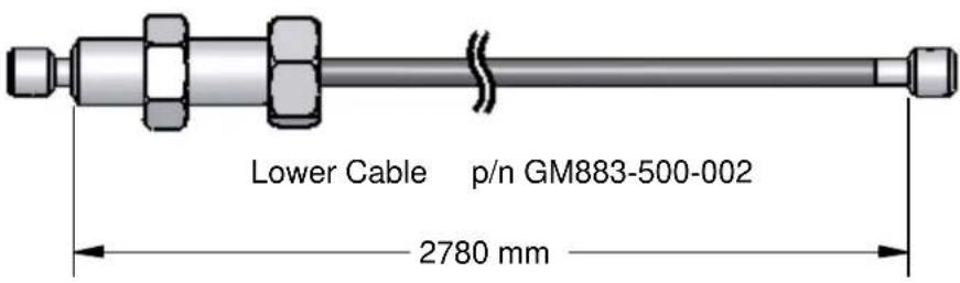
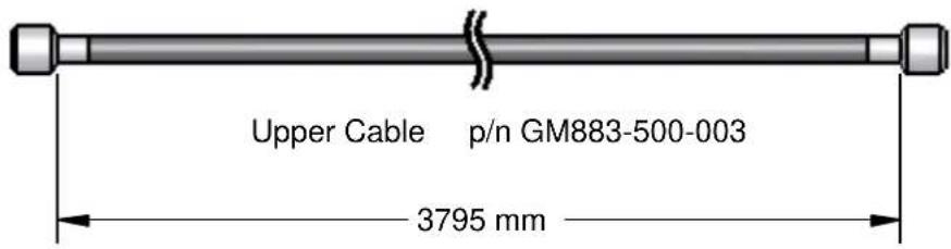
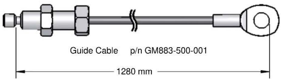
Cable lengths are in millimeters and for reference only.
Cable lengths could change at any time without notice.
ASSEMBLY INSTRUCTIONS
natural_image
3D technical illustration of a fitness machine with levers and arm components (no text or symbols)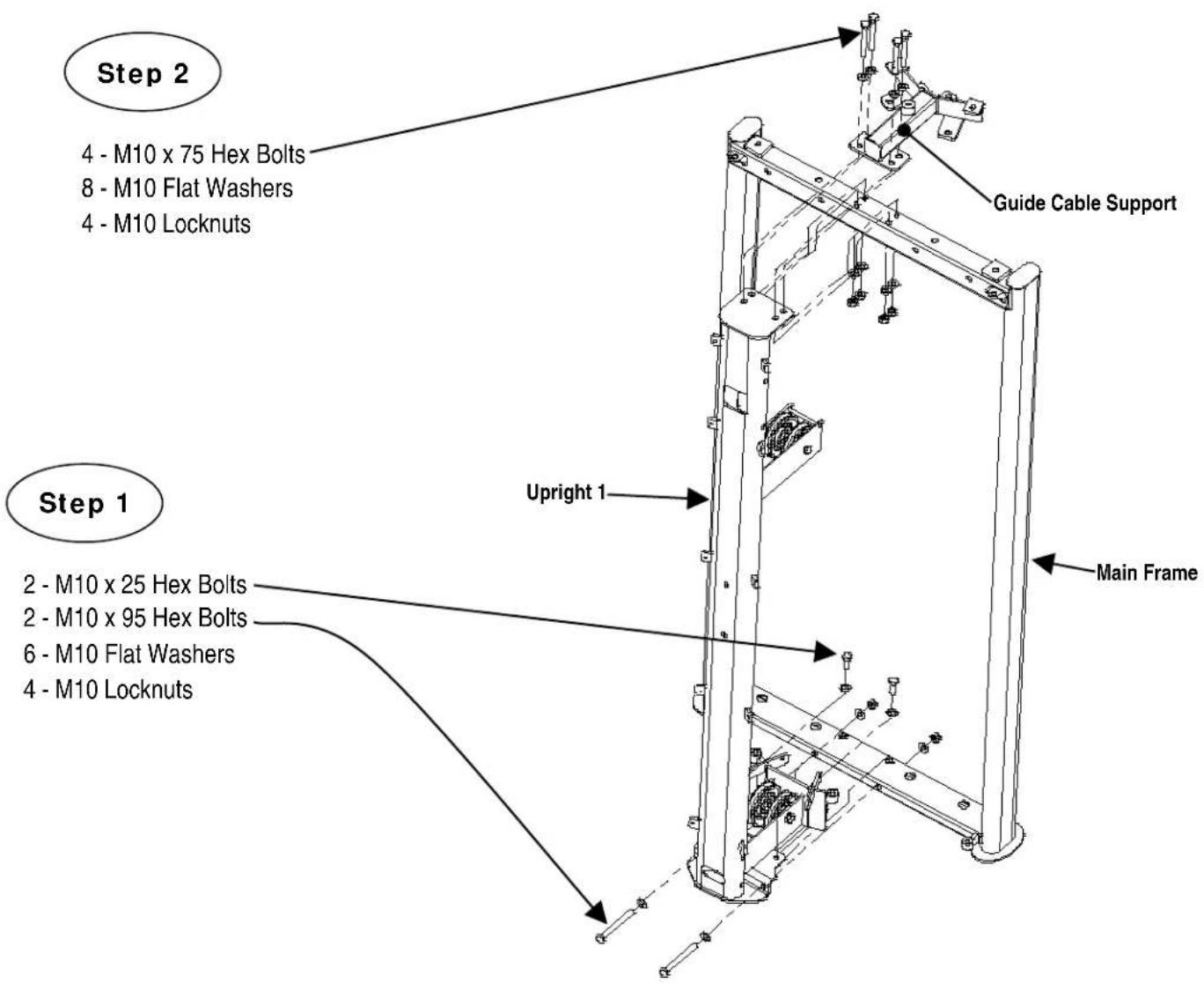
Step 1: Attach Upright 1 to the Main Frame using:
2 - M10 x 95 Hex Bolts
6 - M10 Flat Washers
2 - M10 Locknuts
Step 2: Attach Guide Cable Support to Main Frame and Upright 1 using:
8 - M10 Flat Washers
4 - M10 Locknuts
2 - M10 x 25 Hex Bolts
4 - M10 x 75 Hex Bolts
NOTE: Finger Tighten Only.
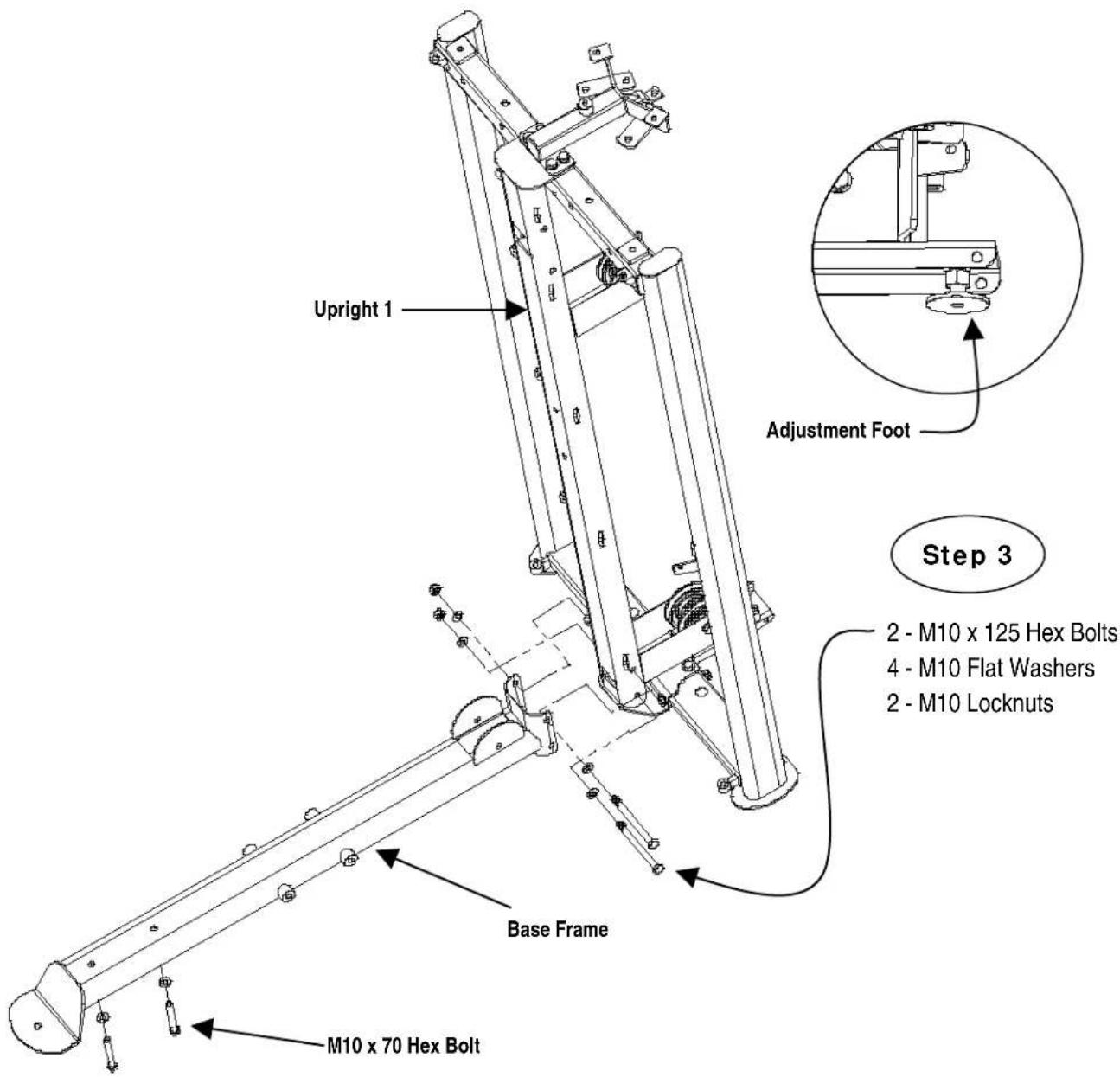
Step 3: Attach the Base Frame to the Upright 1 using:
2 - M10 x 125 Hex Bolts
4 - M10 Flat Washers
2 - M10 Locknuts
Adjust the height of the adjustment foot in the back of the machine so that the adjustment foot is resting on the floor.
NOTE: Finger Tighten Only.
For easier installation of Upright 2 in future step, insert 2- M10 x 70 Hex Bolts and 2- Flat Washers onto the Base Frame from underneath.
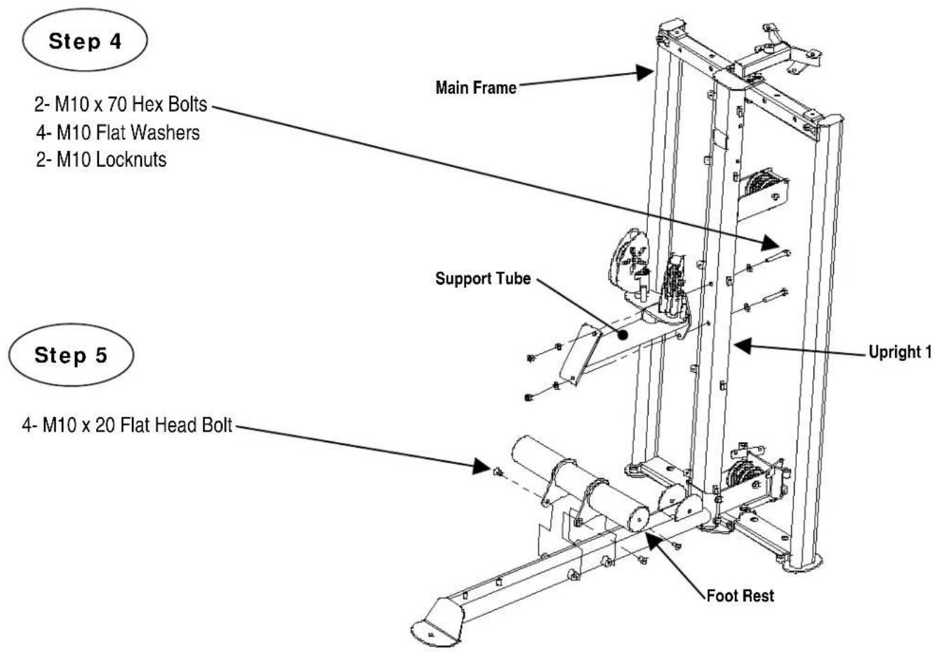
Step 4: Attach the Support Tube to the Upright 1 using:
2 - M10 x 70 Hex Bolts
4 - M10 Flat Washers
2 - M10 Locknuts
NOTE: Finger Tighten Only.
Step 5: Attach the Foot Rest to the Base Frame using:
4 - M10 x 20 Flat Head Bolts
NOTE: Wrench Tighten Now.
Step 6
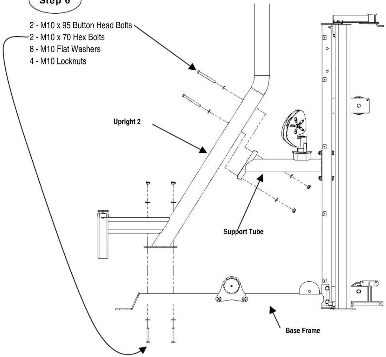
Step 6: Attach the Upright 2 to the Base Frame and Support Tube using:
2 - M10 x 70 Hex Bolts
2 - M10 x 95 Hex Bolts
8 - M10 Flat Washers
4 - M10 Locknuts
NOTE: Finger Tighten Only.
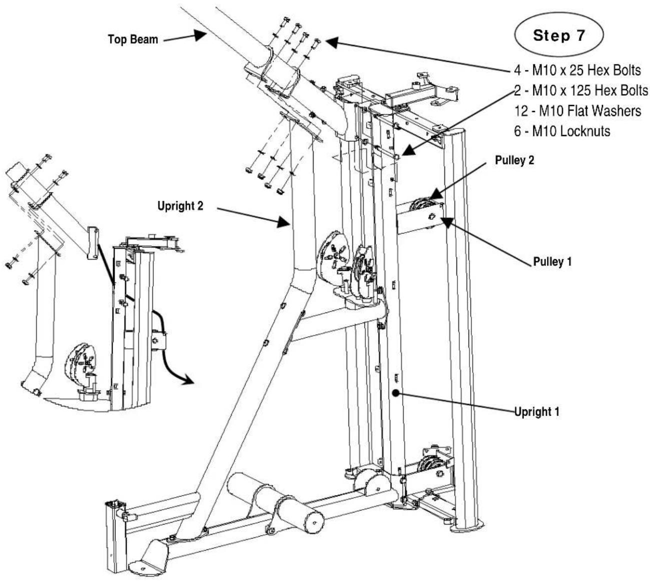
Step 7: Pull the preinstalled cables through the Upright 1 and down and around Pulley 1 and Pulley 2. Make sure that the cables come down straight. Afterwards, connect the Top Beam to the Upright 2 and the Upright 1 using:
4 - M10 x 25 Hex Bolts
2 - M10 x 125 Hex Bolts
12 - M10 Flat Washers
6 - M10 Locknuts
NOTE: Wrench tighten all hardware from Steps 1-7 excluding Step 2 now.
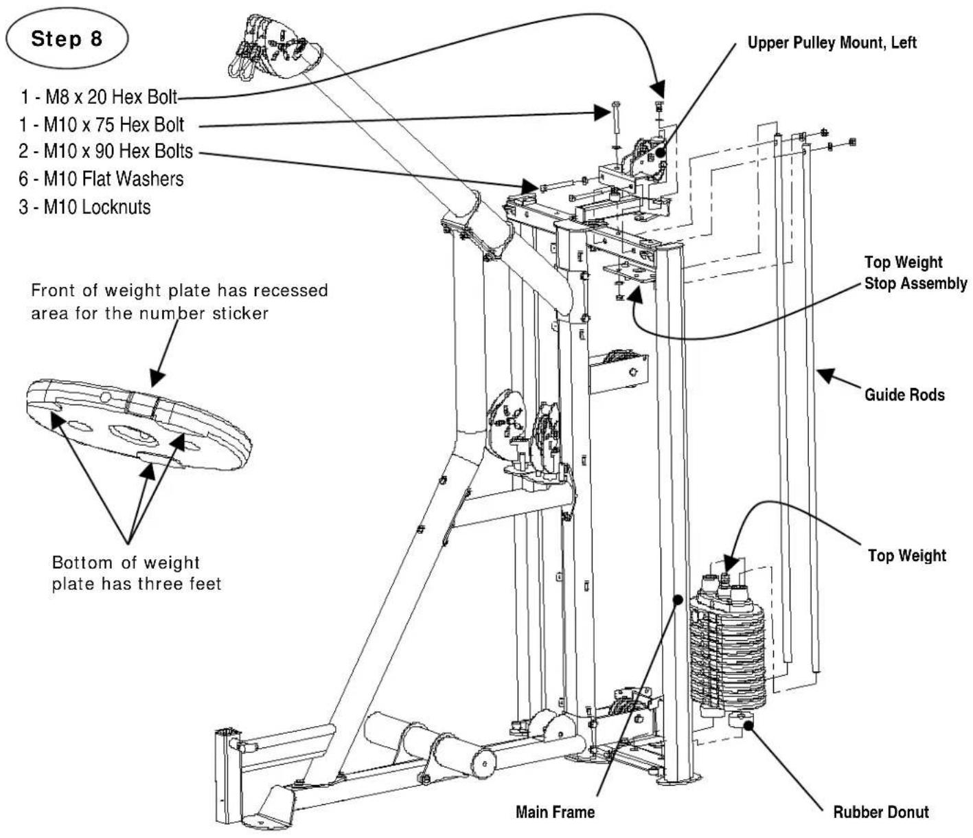
Step 8: Insert two Guide Rods into the holes in the bottom tube of the Main Frame. Carefully tilt the Guide Rods back away from the machine. Slide one Rubber Donut into each Guide Rod. Slide ten Weight Plates onto the Guide Rods. Make sure the recessed area on the front of the weight plate is facing towards the front of the machine. Slide Top Weight assembly onto the Guide Rods. Slide the Top Weight Stop Assembly onto the Guide Rods making sure the rubber pad is facing down. Attach the Upper Pulley Mount, Top Weight Stop Assembly, and Guide Rods to the Main Frame Using:
1 - M10 x 75 Hex Bolt
2 - M10 x 90 Hex Bolts
6 - M10 Flat Washers
3 - M10 Locknuts
1 - M8 Flat Washer
1 - M8 x 20 Hex Bolt
NOTE: Finger Tighten Only.
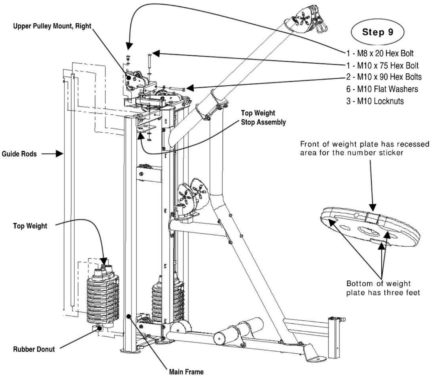
Step 9: Insert two Guide Rods into the holes in the bottom tube of the Main Frame. Carefully tilt the Guide Rods back away from the machine. Slide one Rubber Donut into each Guide Rod. Slide ten Weight Plates onto the Guide Rods. Make sure the recessed area on the front of the weight plate is facing towards the front of the machine. Slide Top Weight assembly onto the Guide Rods. Slide the Top Weight Stop Assembly onto the Guide Rods making sure the rubber pad is facing down. Attach the Upper Pulley Mount, Top Weight Stop Assembly, and Guide Rods to the Main Frame Using:
1 - M10 x 75 Hex Bolt
2 - M10 x 90 Hex Bolts
6 - M10 Flat Washers
3 - M10 Locknuts
1 - M8 Flat Washer
1 - M8 x 20 Hex Bolt
NOTE: Finger Tighten Only.

natural_image
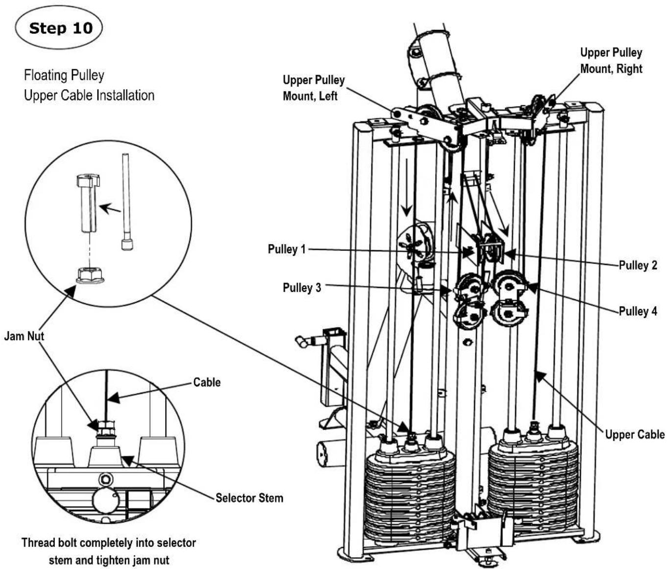
Simple line drawing of a cylindrical rod with two end caps and a central double-headed wire (no text or symbols)Upper Cable p/n GM883-500-003
Step 10: Begin to route the Upper Cables by starting with the left preassembled Upper Cable and pulling it through Pulley 1 and around Pulley 3 of the left floating pulley. Continue through the Upper Pulley Mount, Left and then back down to the Top Weight Stack.
Repeat for the other side with Pulley 2, Pulley 4 and the Upper Pulley Mount, Right.
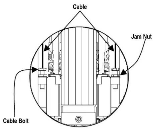
NOTE: Insert Lower Cable into Hex Bolt and Jam Nut as shown above.
Lower Cable p/n GM883-500-002
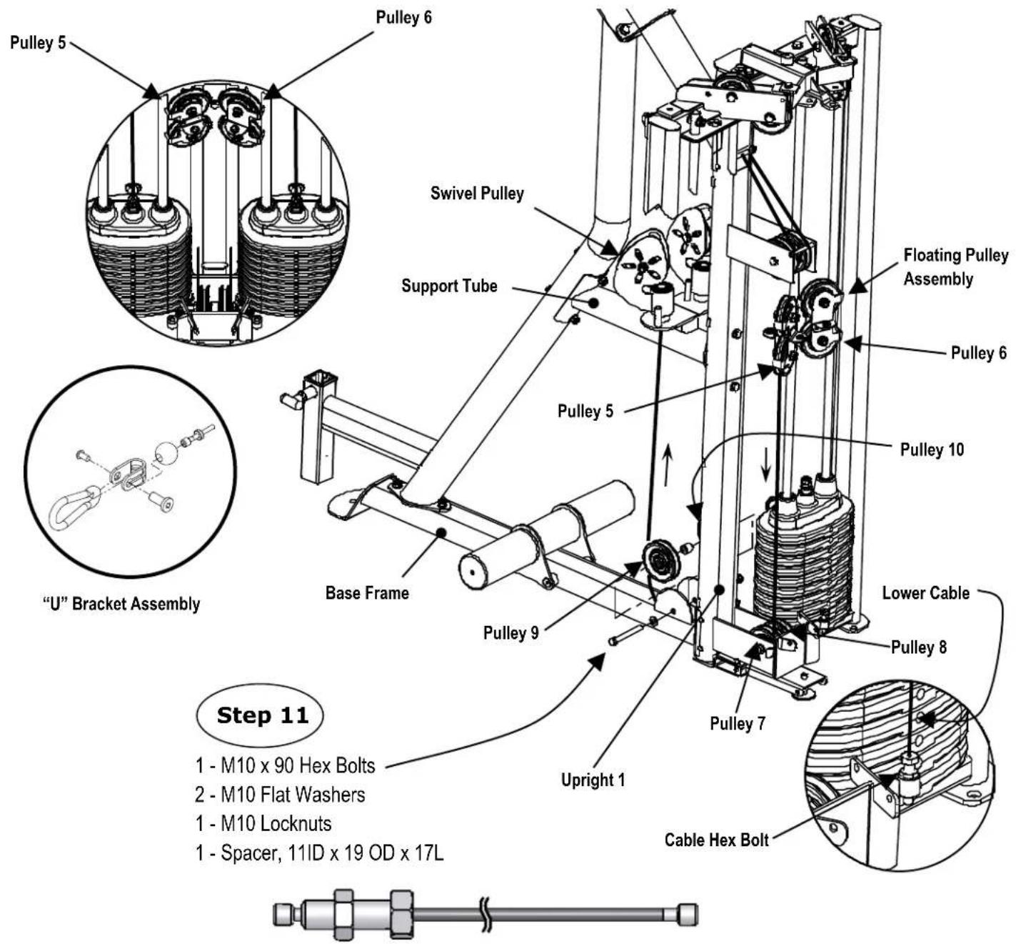
Step 11: Start routing the left Lower Cable by screwing in the Cable Hex Bolt. Then loop the cable around Pulley 5 of the left Floating Pulley Assembly and down through Pulley 7 on the Upright 1. Pass through the Base Frame, up around Pulley 9 and finish routing the cable through the swivel pulley and install the "U" Bracket Assembly.
Repeat for Lower Cable on other side with Pulley 6, Pulley 8, and Pulley 10.
Attach the Pulleys to the Base Frame using:
2 - M10 Flat Washers
1 - M10 Locknuts
1 - M10 x 90 Hex Bolts
1 - Spacer, 11 ID x 19 OD x 17 L
NOTES: Wrench Tighten Now.
Guide Cable p/n GM883-500-001
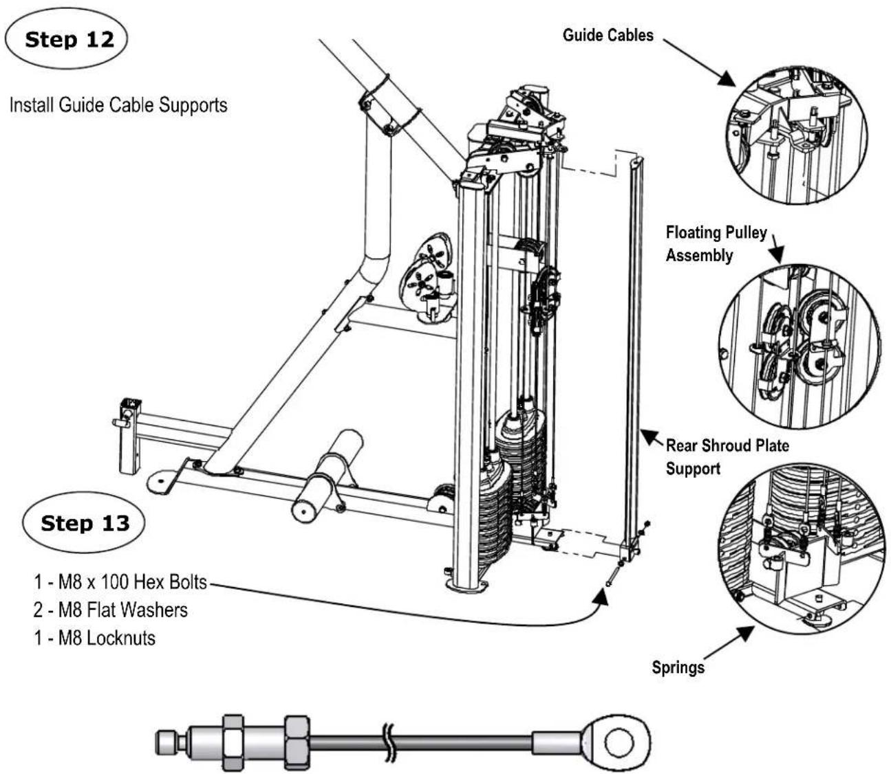
Step 12: Attach one end of a spring to the eyelet and the other end to the hole in the plate at the bottom of Upright 1. Insert the bolt end into the hole in plate on the Guide Cable Support. Make sure there is one jam nut on the bottom side the plate and the other jam nut is on the top side of the plate. Tighten the top jam nut just enough to make the Guide Cable tight. Tighten the bottom jam nut against the bottom of the plate so the bolt will not come loose during use. Remove the black Plastic Bushings from the Floating Pulleys, place Plastic Bushings around Guide Cables and reinstall the Plastic Bushings into the Floating Pulleys.
Step 13: Attach Rear Shroud Plate Support to Main Frame and Upright 1 using:
1 - M8 x 100 Hex Bolts
2 - M8 Flat Washers
1 - M8 Locknuts
Optional: Insert M10 x 50 Fully Threaded Bolt from Step 20 to hold Rear Shroud Plate Support in place.
NOTE: Wrench Tighten Steps 2, 8, 9 and 13 Now.
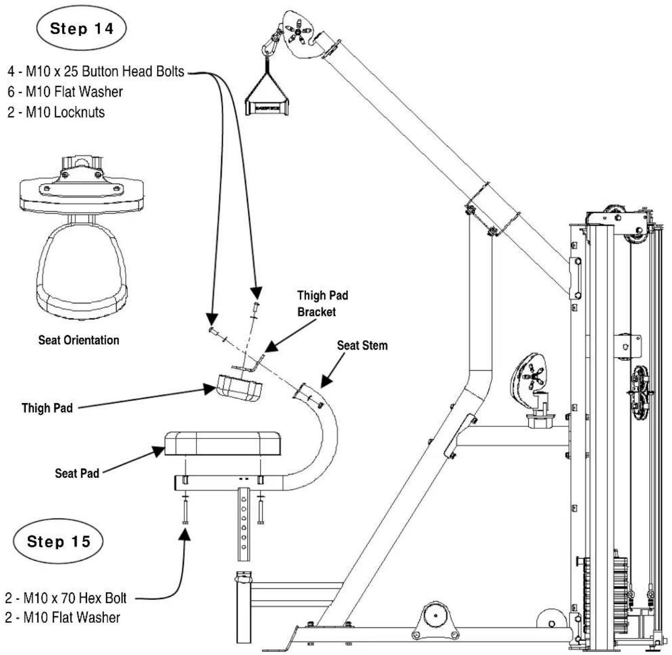
Step 14: Attach the Thigh Pad to the Thigh Pad Bracket and then to the Seat Stem using:
6 - M10 Flat Washers
2 - M10 Locknuts
2 - M10 Flat Washers
4 - M10 x 25 Hex Bolts
2 - M10 x 70 Hex Bolts
Step 15: Attach the Seat Pad to the Seat Stem using:
NOTE: Tighten the hardware Steps 15 and 16 now, but do not over tighten the hardware for the Seat or damage could occur.
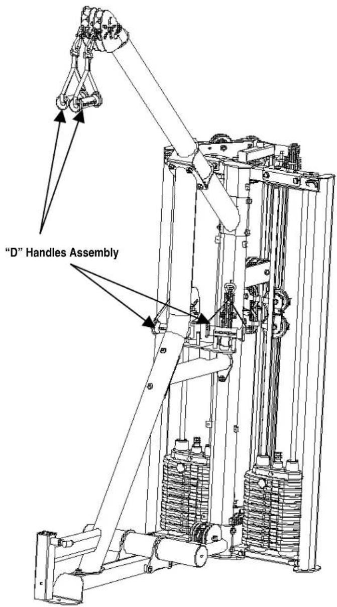
Step 16: Attach the "D" Handle Assembly to the "U" Bracket Assembly in the Upper and Lower Swivel Pulleys.
NOTE: At this point it is necessary to seat the cables. Start by verifying that cables are centered in the grooves of all pulleys. Next, select a weight you can comfortably handle on the Lat/Row. Pull the upper handles and lightly bounce the weight up and down for about 5 seconds and then repeat for the lower handles. This will seat the cables into the pulleys and prepare the Lat/Row for Step 17.
Step 17: Eliminate cable slack by changing the height of the Cable Bolt on Upright 1. Make sure at least 12 of the cable bolt is in Upright 1. Wrench Tighten Jam Nut.

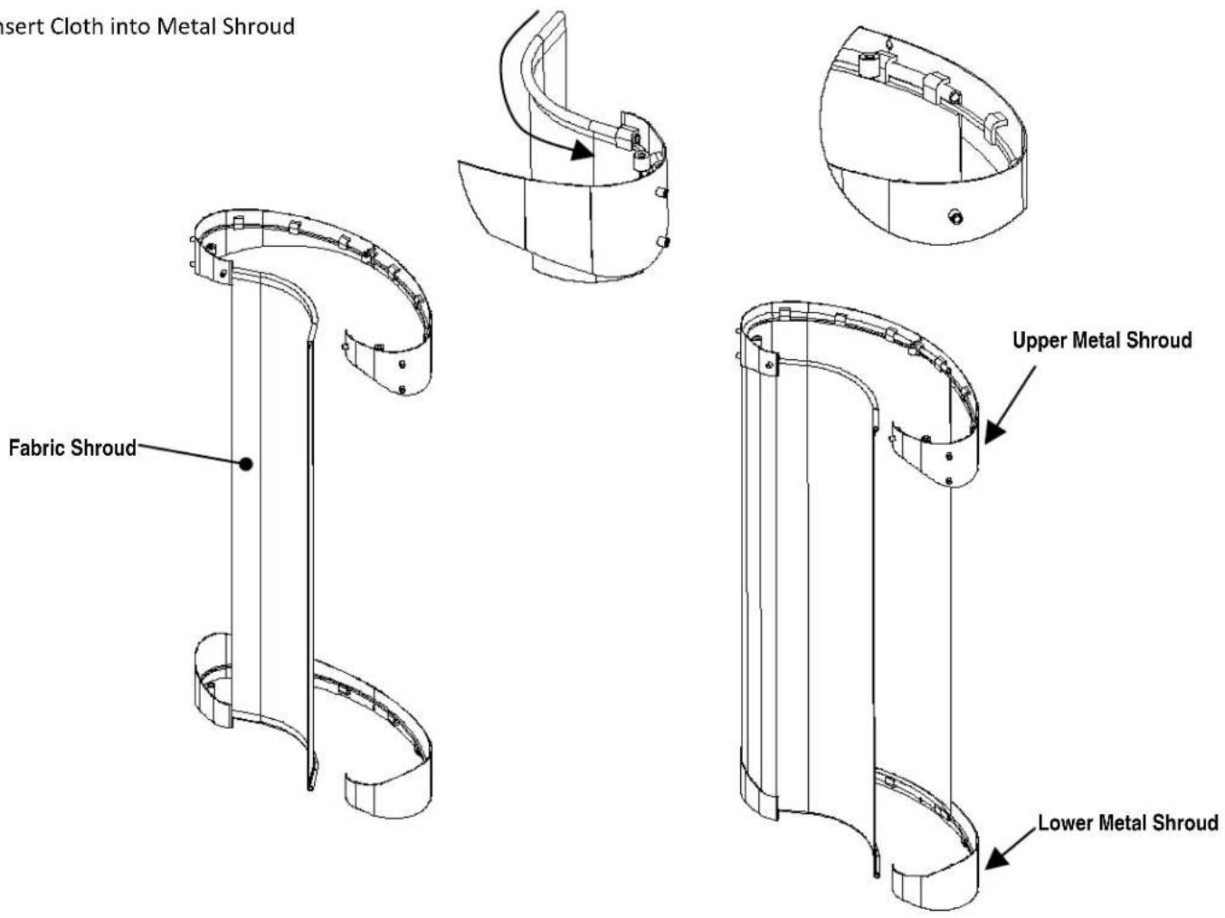
Step 16: To install Fabric Shroud, start from one end of the Lower Metal Shroud and insert the Fabric Shroud inwards as shown. Make sure to have the same orientation as shown or else the fabric shroud will be installed backwards. Continue to pull the Fabric Shroud along the inside of the Lower Metal Shroud until it approaches the other end.
Repeat above for the Upper Metal Shroud. Be sure to pull tight as fabric shroud is wrapped.
If ripples appear on the fabric shroud, stretch and smooth out the fabric shroud to give a nice smooth consistency to the shroud.
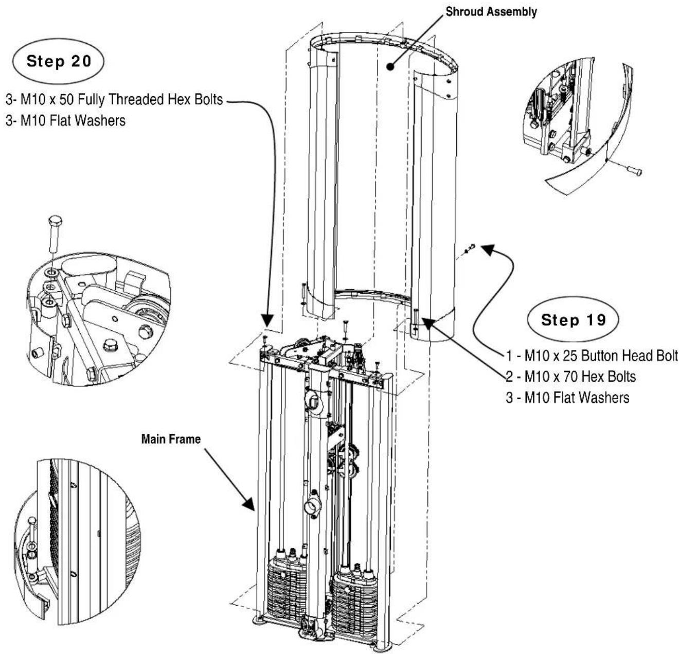
Step 19: Attach the Lower Metal Shroud to the Upright 1 and Main Frame using:
1 - M10 x 25 Button Head Bolt
2 - M10 x 70 Hex Bolts
3 - M10 Flat Washers
NOTE: Wrench Tighten Now.
3 - M10 x 50 Fully Threaded Bolts
3 - M10 Flat Washers
NOTE: Tighten bolts until fabric shroud is tight.
Step 20: Attach the Upper Metal Shroud to the Guide Cable Support and Main Frame using:
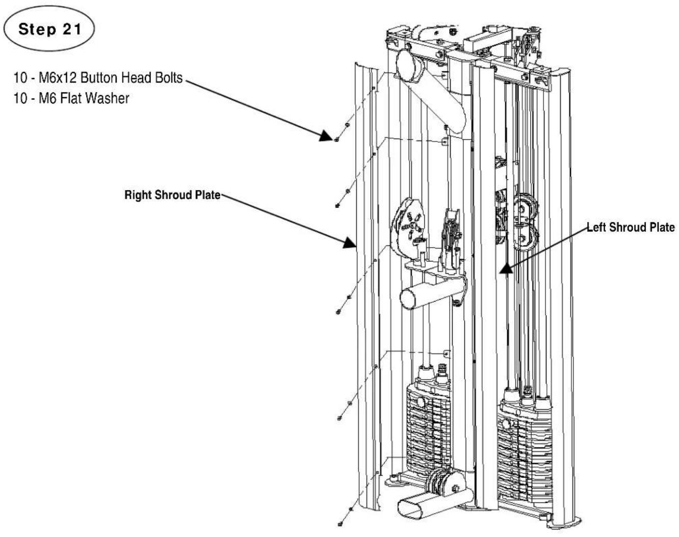
Step 21: Attach Right and Left Metal Shroud Plates to Upright 1 using:
10 - M6 x 12 Button Head Bolts
10 - M6 Flat Washers
NOTE: Wrench Tighten Now.
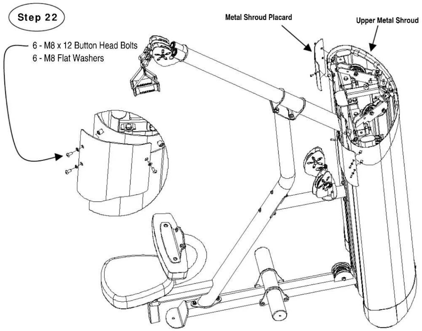
Step 22: Attach the Metal Shroud Placard to the Upper Metal Shroud using:
6 - M8 x 12 Button Head Bolts
6 - M8 Flat Washers
NOTE: Wrench Tighten Now.
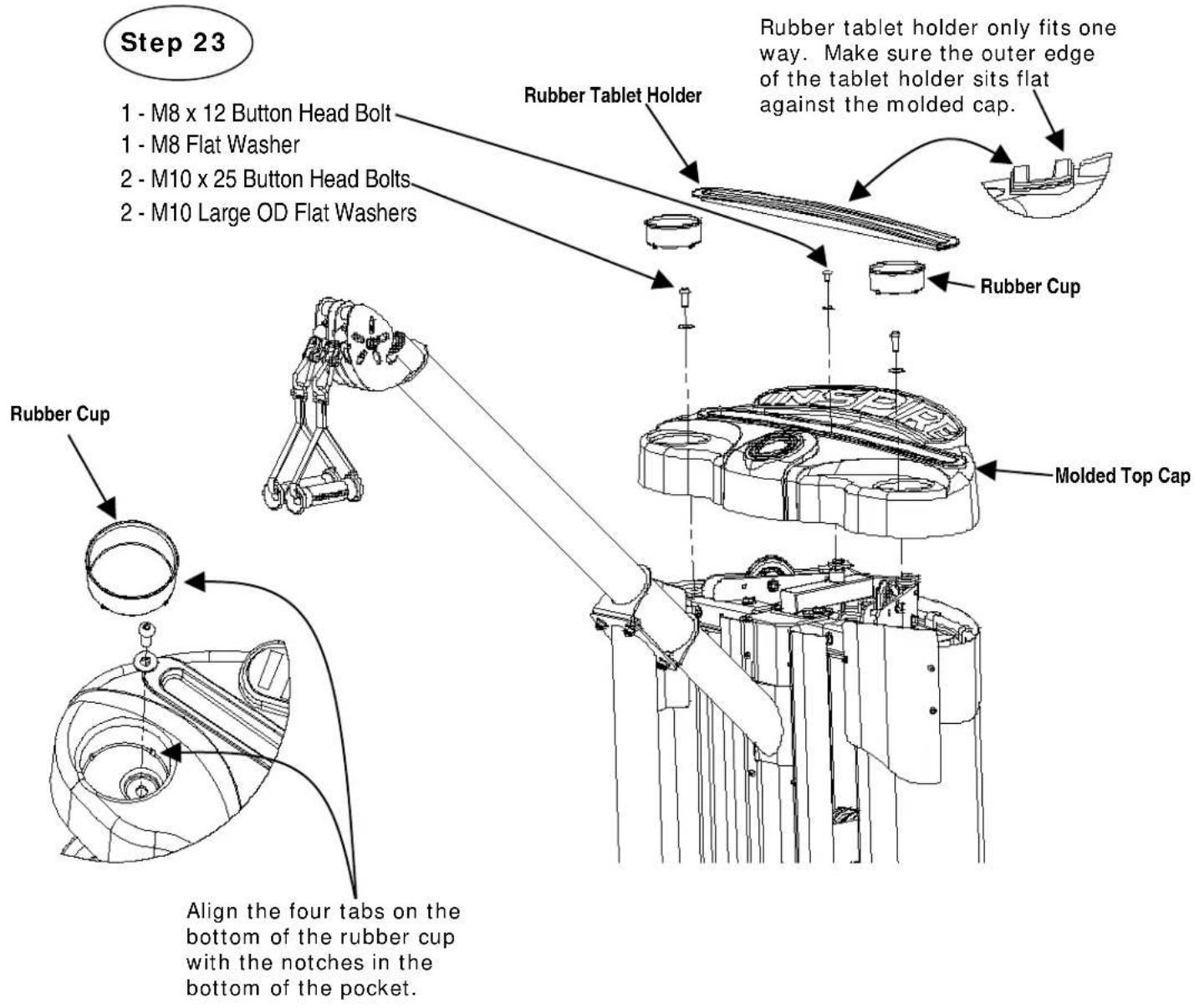
Step 23: Attach the Molded Top Cap to the Main Frame using:
2 - M10 x 25 Button Head Bolts
1 - M8 x 12 Button head Bolts
2 - M10 Large OD Flat Washers
Note : Tighten bolts, but do not over tighten.
1 - M8 Flat washer
Align the four tabs on the bottom of the Rubber Cups with the four notches in the bottom of the pockets in the Molded Top Cap and insert the Rubber Cups into the pockets.
Insert the Rubber Tablet Holder into the Pocket in the Molded Top Cap. The Rubber Tablet Holder only fits one way. Make sure the outer edge of the Rubber Tablet Holder sits flat against the Molded Top Cap.
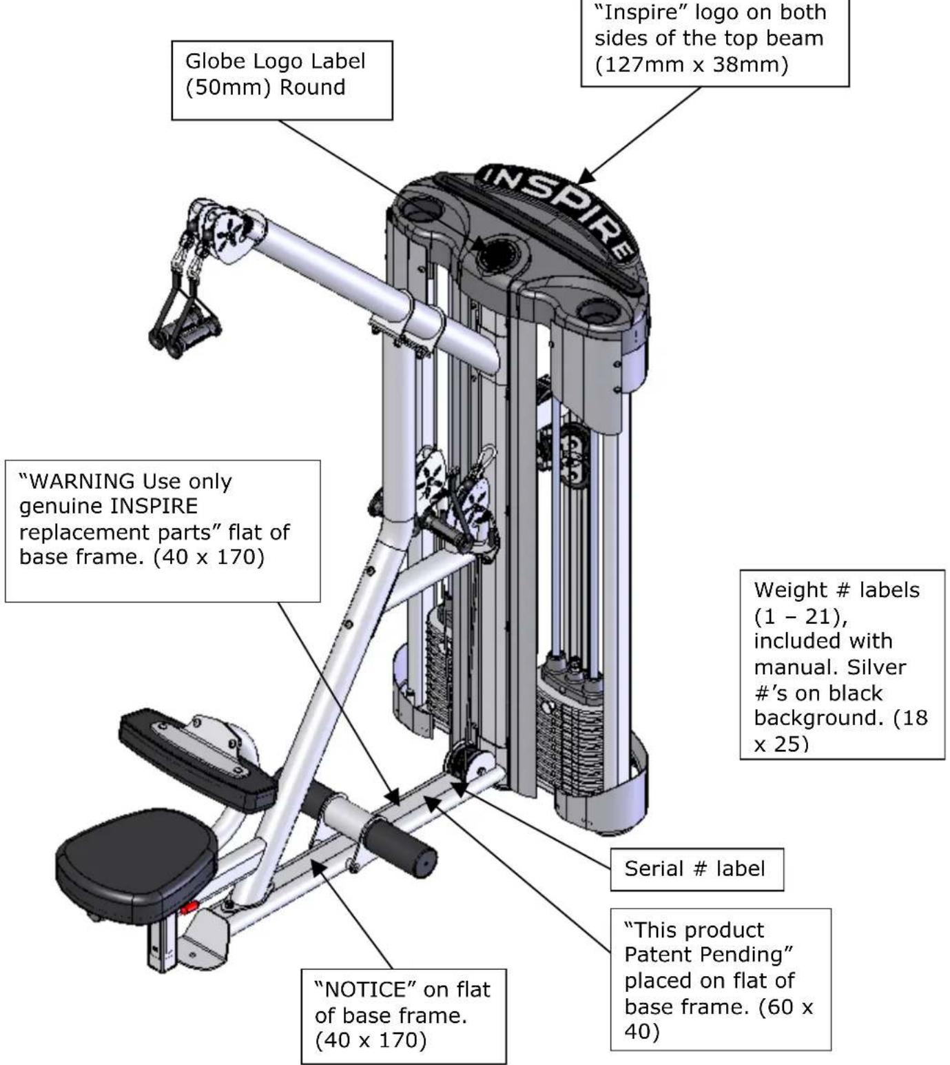
DECAL REFERENCE
NOTICE
| This INSPIRE product is notintended for commercial use. | ||||
| IN HOME MAINTENANCE | Weekly | 3Months | Yearly | 2Years |
| Inspect; Links,Pull Pins, SnapLocks, Swivels,Weight StackPins | ✕ | |||
| Clean;Upholstery | ✕ | |||
| Inspect; Cablesand theirfittings | ✕ | |||
| Inspecttaughtness of allshrouds | ✕ | |||
| Inspect;Accessory Barsand Handles | ✕ | |||
| Inspect;All Decals | ✕ | |||
| Inspect; All nutsand BoltsTighten ifNeeded. | ✕ | |||
| Inspect;Anti-SkidSurfaces | ✕ | |||
| Clean &Lubricate;Guide Rods witha Teflon(PTFE)based lubricant(Superlube) | ✕ | |||
| Lubricate; SeatSleeves andall plastic slides | ✕ | |||
| Clean & Wax; AllGlossy Finishes | ✕ | |||
| Replace; Cables,Belts andConnectinParts. | ✕ | |||
INSPIRE™
BY HEALTH IN MOTION LLC
877-738-1729
www.inspirefitness.net
Serial #4-05-05-00001
This product covered by one or more of the following US Patents and others pending: 5,330,405; 5,944,641; 5,961,427; 7,645,217; 7,722,513; 7,837,600; 7,905,818; 8,096,929.; 8,870,718.
WARNING
USE ONLY GENUINE INSPIRE REPLACEMENT PARTS. FAILURE TO DO SO WILL VOID WARRANTY AND COULD RESULT IN SERIOUS INJURY. THERE IS A RISK ASSUMED BY INDIVIDUALS WHO USE THIS TYPE OF EQUIPMENT. TO MINIMIZE THE RISK, ALWAYS FOLLOW THESE RULES.
-
READ & UNDERSTAND ALL ENCLOSED INSTRUCTIONS BEFORE USING THIS EQUIPMENT.
-
INSPECT EQUIPMENT BEFORE EACH USE. Replace parts that show any wear or damage. If in doubt about a certain part, DO NOT use the equipment until the part is replaced. Failure to replace worn or damaged parts may result in injury.
-
FOLLOW MAINTENANCE SCHEDULE on the "NOTICE" sticker
-
CONSULT YOUR PHYSICIAN BEFORE STARTING ANY EXERCISE PROGRAM. Warm up properly before exercising. Stop exercising if you feel faint or dizzy.
-
TO PREVENT THE POSSIBILITY OF SERIOUS INJURY, KEEP CLEAR OF ALL MOVING PARTS. DO NOT ATTEMPTO FREE ANY JAMMED PART BY YOURSELF. Obtain assistance in order to avoid possible injury.
-
Take your lime and do not rush exercise. Practice proper breathing, NEVER hold your breath.
-
CHILDREN SHOULD NOT BE ALLOWED TO USE THIS EQUIPMENT. To avoid possible injury, children should be kept at a sale distance when this equipment is in use. Teenagers should not use this equipment without adult supervision.
-
CALL YOUR AUTHORIZED INSPIRE DISTRIBUTOR if you have any questions on the proper use or maintenance of this equipment.

PAGE 22
DECAL REFERENCE
INSPIRE
| LATROW | ||
| No. | lb. | kg. |
| 1 | 10 | 5 |
| 2 | 20 | 9 |
| 3 | 30 | 14 |
| 4 | 40 | 18 |
| 5 | 50 | 23 |
| 6 | 60 | 27 |
| 7 | 70 | 32 |
| 8 | 80 | 36 |
| 9 | 90 | 41 |
| 10 | 100 | 45 |
| 11 | 110 | 50 |

natural_image
Abstract circular logo with interlocking white rings on black background (no text or symbols)DECAL PLACEMENT
ACCESSORIES
- 4 – “D” Handle Assembly
Training Tips
CONSULT A PHYSICIAN BEFORE STARTING ANY EXERCISE PROGRAM
- Always warm up before you start weight training. This helps get your muscles warm and prevents injury. You can warm up with light cardio or by doing a light set of each exercise before going to heavier weights.
- Control the weight. Always work with a weight that you can handle through a full range of motion. Slow and steady movements are recommended.
- Breathe. Don't hold your breath during your set. Holding your breath builds internal pressure which increases your change for broken blood vessels, as well as a hernia.
- Sit up straight. Pay attention to your posture and keep everything straight. Engage your abs in every movement to keep balanced and protect your spine.
GENERAL MAINTENANCE INFORMATION
- Periodically inspect the cables for splitting, cracking or fraying. Also, watch for bulging or flat areas in the cable.
- Immediately replace cables at the first signs of damage or wear. Never use equipment with damaged or worn cables.
- Cables naturally stretch over time, so check cable slack periodically and adjust cable tension as needed.
- Regularly inspect product for loose hardware.
- Do not use or store equipment outdoors.
- Inspect snap links, swivels, handles and weight stack pin for wear or damage. If wear or damage exists, replace immediately.
- Locate and familiarize yourself with all warning decals on the machine.
- Replace damaged or worn upholstery immediately.
- Periodically wipe down guide rods with a dry cloth and re-apply a thin coat of a teflon-based lubricant.
MAINTENANCE SCHEDULE
| ROUTINE | COMMERCIAL/ LIGHT COMMERCIAL MAINTENANCE | HOME MAINTENANCE | ENTRY DATE | ||||||
| Inspect: Links, Pull Pins, Spring Clips, Swivels, Weight Stack Pins. | DAILY WEEKLY | ||||||||
| Clean: Upholstery. | DAILY WEEKLY | ||||||||
| Inspect: Cables and their Fittings for wear or looseness. | DAILY WEEKLY | ||||||||
| Inspect: Tautness of all Shrouds. | DAILY WEEKLY | ||||||||
| Inspect: Accessory Bars and Handles. | WEEKLY 3 MONTHS | ||||||||
| Inspect: All Decals. | WEEKLY 3 MONTHS | ||||||||
| Inspect: All Nuts and Bolts. Tighten if Needed. | WEEKLY 3 MONTHS | ||||||||
| Inspect: Anti-Skid surfaces. | WEEKLY 3 MONTHS | ||||||||
| Clean and Lubricate: Guide Rods with a Teflon based lubricant. | WEEKLY 3 MONTHS | ||||||||
| Lubricate: Seat Sleeves, all Plastic Slides, and Linear Bearings. | WEEKLY 3 MONTHS | ||||||||
| Clean and Wax: All Glossy Finishes. | 6 MONTHS YEARLY | ||||||||
| Replace: Cables, Belts, and Connecting Parts. | YEARLY 2 YEARS | ||||||||
INSPIRE
Warranty.
This Warranty applies to Inspire Strength products manufactured or distributed by Health In Motion LLC.
CONSUMER USE:
LIMITED LIFETIME FRAME:
Includes Frame and Welds
LIMITED LIFETIME PARTS:
Includes Upholstery, Hardware, etc.
LIMITED LIFETIME MOVING PARTS:
Includes Pulleys, Cables, etc.
LIGHT-COMMERCI AL USE:
LIMITED LIFETIME FRAME:
Includes Frame and Welds
10 YEAR PARTS:
Includes Upholstery, Hardware, etc.
10 YEAR MOVING PARTS:
Includes Pulleys, Cables, etc.
COMMERCIAL USE:
LIMITED LIFETIME FRAME:
Includes Frame and Welds
1 YEAR PARTS:
Includes Upholstery, Cables, Hardware etc.
5 YEAR MOVING PARTS:
Includes Pulleys, Bearings, etc.
PLEASE NOTE THAT NOT ALL INSPIRE PRODUCTS ARE MADE FOR LIGHT-COMMERIAL OR COMMERCIAL USE
Refer to your Owner's Manual or consult with your fitness product dealer to establish if a Product is made for consumer, light-commercial, or commercial use or not. Using a non-commercial product in a commercial setting can result in serious injury or death!
Health In Motion warrants that the Product you have purchased for commercial, light-commercial, personal, family or household use from Health In Motion LLC or from an authorized Health In Motion reseller is free from defects in materials or workmanship under normal use during the warranty period. Your sales receipt, showing the date of purchase of the Product, is your proof of the date of purchase. This warranty extends only to you, the original purchaser. It is not transferable to anyone who subsequently purchases the Product from you. It excludes expendable parts such as paint and finish. This Warranty becomes VALID ONLY if the Product is assembled / installed according to the instructions / directions included with the Product.
Replacement and repair of parts.
During the warranty period Health In Motion will repair or replace the Product if it becomes defective, malfunctions, or otherwise fails to conform with this Warranty under normal light-commercial, personal, family, or household use. In repairing the product Health In Motion may replace defective parts with, at the option of Health In Motion, serviceable used parts that are equivalent to new parts in performance, or new parts. All exchanged parts and Products replaced under this warranty will become the property of Health In Motion. Health In Motion reserves the right to change manufacturers and or specification of any part to cover any existing warranty.
Service procedures.
To obtain warranty parts, you must return the parts to Health In Motion or an authorized Health In Motion retailer in its original container (or equivalent). You must pre-pay any shipping charges, taxes, or any other charges associated with transportation of the Product. In addition, you are responsible for insuring any Product shipped or returned. You assume the risk of loss during shipment. You must present Health In Motion with proof-of-purchase documents (including the date of purchase, Model, and Serial Number). Any evidence of alteration, erasing or forgery of proof-of-purchase documents will be cause to void this Warranty. Register your warranty online visit www.inspirefitness.com
Conditions and Exceptions.
This Warranty does not extend to any Product not purchased from Health In Motion LLC or from an authorized Health In Motion reseller. This Warranty does not extend to any Product that has been damaged or rendered defective; (a) as a result of accident, misuse, or abuse; (b) by the use of parts not manufactured or sold by Health In Motion; (c) by modification of the Product; (d) as a result of service by anyone other than Health In Motion, or an authorized Health In Motion warranty service provider; (e) product that has not been properly maintained (follow maintenance schedule found on product). Should any product submitted for Warranty service be found to be ineligible, an estimate of repair cost will be furnished and the repair will be made if requested by you upon Health In Motion receipt of payment or acceptable arrangement of payment.
Disclaimer
EXCEPT AS EXPRESSLY SET FORTH IN THIS WARRANTY HEALTH IN MOTION MAKES NO OTHER WARRANTIES; EXPRESSED OR IMPLIED INCLUDING ANY IMPLIED WARRANTIES OF MERCHANTABILITY AND FITNESS FOR A PARTICULAR PURPOSE. HEALTH IN MOTION EXPRESSLY DISCLAIMS ALL WARRANTIES NOT STATED IN THIS WARRANTY. ANY IMPLIED WARRANTIES THAT MAY BE IMPOSED BY LAW ARE LIMITED TO THE TERMS OF THIS WARRANTY. NEITHER HEALTH IN MOTION NOR ANY OF ITS AFFILIATES SHALL BE RESPONSIBLE FOR INCIDENTAL OR CONSEQUENTIAL DAMAGES. HEALTH IN MOTION IS NOT RESPONSIBLE FOR THE REPAIR OR REPLACEMENT OF ANY PARTS THAT HEALTH IN MOTION DETERMINES HAVE BEEN SUBJECTED AFTER THE DATE OF MANUFACTURE TO ALTERATION, NEGLECT, ABUSE, MISUSE, NORMAL WEAR & TEAR, ACCIDENT, DAMAGE DURING TRANSIT OR INSTALLATION, FIRE, FLOOD, OR ANY ACT OF GOD. SOME STATES DO NOT ALLOW LIMITATIONS ON HOW LONG AN IMPLIED WARRANTY LASTS OR THE EXCLUSION OR LIMITATION OF INCIDENTAL OR CONSEQUENTIAL DAMAGES, SO THE ABOVE LIMITATIONS OR EXCLUSION MAY NOT APPLY TO YOU. This Warranty gives you specific legal rights and you may also have other rights that may vary from state to state. This is the only express warranty applicable to Health In Motion's "Inspire" branded strength products. Health In Motion neither assumes nor authorizes anyone to assume for it any other express warranty.