SF5 - Fitness Equipment INSPIRE - Free user manual and instructions
Find the device manual for free SF5 INSPIRE in PDF.


| Product Type | Smith Machine with Cable Crossover |
| Brand | Inspire |
| Model | SF5 |
| Overall Dimensions (H x W x D) | 87 x 50 x 65 inches |
| Weight | 450 lbs |
| Maximum User Weight | 350 lbs |
| Weight Stack | Two 150 lb stacks (total 300 lbs) |
| Bar Weight (Smith) | 20 lbs (counterbalanced) |
| Frame Material | 11-gauge steel |
| Pull-up Bar | Yes, multi-grip |
| Attachments Included | Lat bar, low row bar, stirrup handles, ankle strap, tricep rope, straight bar |
| Safety Features | Spotting arms, safety catches, weight stack pins |
| Guide Rods | 4 linear bearings per stack |
| Pulley System | Dual cable crossover with adjustable pulleys |
| Landmine Attachment | Included |
| Assembly Time | 2-3 hours (2 people recommended) |
| Warranty | Lifetime on frame, 1 year on moving parts |
| Maintenance | Lubricate guide rods monthly; wipe down after use |
| Cleaning | Mild soap and water; avoid abrasive cleaners |
| Repairability | Replacement parts available via Inspire customer service |
Frequently Asked Questions - SF5 INSPIRE
User questions about SF5 INSPIRE
0 question about this device. Answer the ones you know or ask your own.
Ask a new question about this device
Download the instructions for your Fitness Equipment in PDF format for free! Find your manual SF5 - INSPIRE and take your electronic device back in hand. On this page are published all the documents necessary for the use of your device. SF5 by INSPIRE.
USER MANUAL SF5 INSPIRE
natural_image
Technical line drawing of a gym machine with adjustable arms and legs (no text or symbols)Machine shown with optional bench and rack attachment
Record Serial Number Here
Health in Motion LLC
V09222023
MADE IN CHINA

INSPIRE
SFS
CONGRATULATIONS
Welcome to the Inspire Fitness Family. You've just taken the first step to a healthier and stronger body. This SFS Smith Machine Functional Trainer by Inspire Fitness offers the key to unlocking your body's potential. Regular training on a Smith Machine Functional Trainer has been shown to deliver a host of benefits including: increased muscle tone, decreased body fat, improved energy levels, and a reduction in stress. Congratulations, you are on your way to improving your self image, overall health, and quality of life.
BEFORE ASSEMBLING YOUR SF5
IMPORTANT: Read this entire manual before attempting to build or use this machine. This manual contains step by step instructions for proper assembly.
Use the parts list included in this manual to verify that all parts are accounted for before assembly. If any parts are missing, contact Inspire Fitness Support for replacement parts through email, by phone or through chat.
This Inspire Fitness SF5 Smith Machine Functional Trainer is intended for indoor use only. Rust can form on certain parts in a humid environment, resulting in impaired function:
CONTACT US FOR HELP
Service of your SFS Smith Machine Functional Trainer should only be performed by an Inspire Fitness Authorized Servicer. Service performed by anyone else can result in loss of warranty. If you need help finding an Inspire Fitness Authorized Servicer, please contact us directly:

Hello@centr.com

Phone
+1 877-738-1729 (US Only)
+1 714-738-1729 (Global)
Mon-Fri 8am-5pm PT - UTC-7h/8h

Chat
www.inspirefitness.com
TABLE OF CONTENTS
PRODUCT WARRANTY....5
IMPORTANT SAFETY NOTICE....5
ASSEMBLY AND SETUP....6
ASSEMBLY INSTRUCTIONS....10
FEATURES AND FUNCTIONS....19
LABEL PLACEMENT....20
LIVE AREA....21
PRODUCT DIMENSIONS....22
MAINTENANCE....23
EXPLODED VIEW....24
PARTS LISTS....25
PRODUCT WARRANTY
To view full warranty details, or to register your product for warranty, visit inspirefitness.com/support
AUSTRALIA
Our goods come with guarantees that cannot be excluded under the Australian Consumer Law. You are entitled to a replacement or refund for a major failure and for compensation for any other reasonably foreseeable loss or damage. You are also entitled to have the goods repaired or replaced if the goods fail to be of acceptable quality and the failure does not amount to a major failure.
Our goods and services come with guarantees that cannot be excluded under the Australian Consumer Law. For major failures with the service, you are entitled:
• to cancel your service contract with us; and
• to a refund for the unused portion, or to compensation for its reduced value.
You are also entitled to choose a refund or replacement for major failures with goods. If a failure with the goods or a service does not amount to a major failure, you are entitled to have the failure rectified in a reasonable time. If this is not done you are entitled to a refund for the goods and to cancel the contract for the service and obtain a refund of any unused portion. You are also entitled to be compensated for any other reasonably foreseeable loss or damage from a failure in the goods or service.
IMPORTANT SAFETY NOTICE
PRECAUTIONS
This exercise machine is built for optimum safety. However, certain precautions apply whenever you operate a piece of exercise equipment. Be sure to read the entire manual before you assemble or operate your machine. Please note the following safety precautions:
- Consult your physician before beginning any exercise program
- Always keep children and pets away from the machine. DO NOT leave children unattended in the same room with the machine. The cabling and moving parts on this machine can cause serious injury or death if used improperly.
- Only one person at a time should use the machine.
- If the user experiences dizziness, nausea, chest pain, or any other abnormal symptoms, STOP the workout at once. CONSULT A PHYSICIAN IMMEDIATELY.
- Position the machine on a clear, leveled surface. DO NOT use the machine near water or outdoors.
- Keep hands away from all moving parts.
- Always wear appropriate workout clothing when exercising. DO NOT wear robes or other loose clothing that could become caught in the machine. Running or training shoes are also required when using the machine.
- Use the machine only for its intended use as described in this manual. DO NOT use attachments not recommended by the manufacturer.
- DO NOT place any sharp objects around the machine.
- Disabled persons should not use the machine without a qualified person or physician in attendance.
- Before using the machine to exercise, always do stretching exercises to properly warm up.
- Never operate the machine if the machine is not functioning properly.
Care and Maintenance
- Inspect and tighten all parts before using the machine.
• The Frame and Seat Pad of the machine can be c leaned using a damp cloth and mild non-abrasive detergent. DO NOT use solvents
WARNING: BEFORE BEGINNING ANY EXERCISE PROGRAM, CONSULT YOUR PHYSICIAN. THIS IS ESPECIALLY IMPORTANT FOR INDIVIDUALS OVER THE AGE OF 35 OR PERSONS WITH PRE-EXISTING HEALTH PROBLEMS. READ ALL INSTRUCTIONS BEFORE USING ANY FITNESS EQUIPMENT. Health In Motion, LLC. DOES NOT ASSUME ANY RESPONSIBILITY FOR PERSONAL INJURY OR PROPERTY DAMAGE SUSTAINED BY OR THROUGH THE USE OF THIS PRODUCT.
ASSEMBLY AND SETUP
Package Contents
A Box Contents
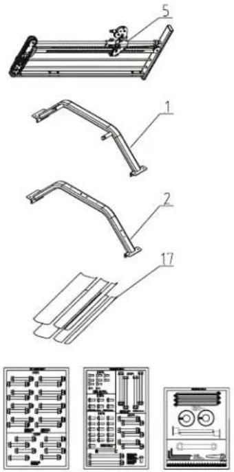
Internal Accessory Box Contents
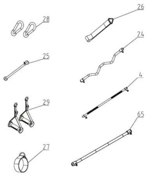
B Box Contents
Internal Accessory Box Contents 1
Internal Accessory Box Contents 2
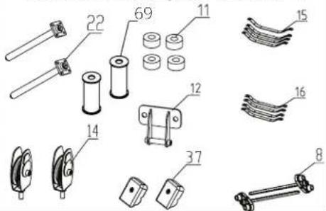
Internal Accessory Box Contents 3
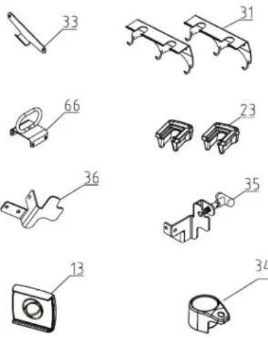
Assembly Hardware Kit (Not to Scale)
SF5 (GM6970-05)3-1
STEP1
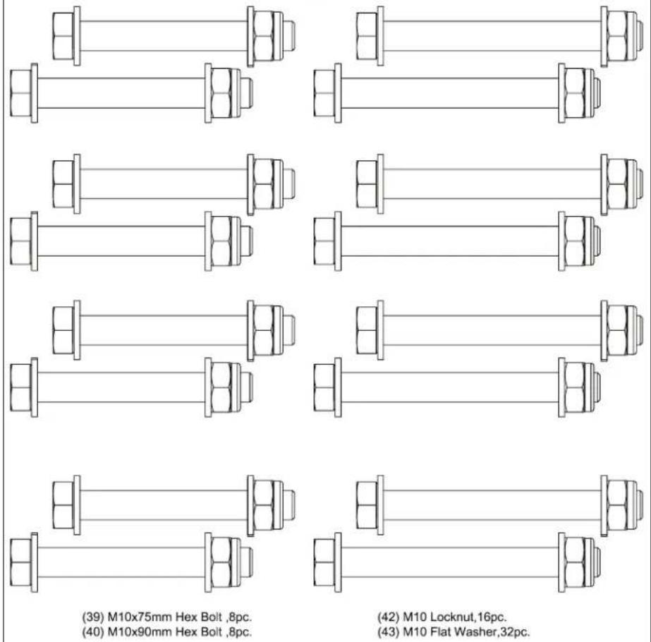
(39) M10x75mm Hex Bolt, 8pc.
(40) M10x90mm Hex Bolt, 8pc.
(42) M10 Locknut, 16pc.
(43) M10 Flat Washer, 32pc.
STEP2

(39) M10x75mm Hex Bolt, 8pc.
(42) M10 Locknut, 8pc.
(43) M10 Flat Washer, 16pc.
SF5(GM6970-05)3-2
STEP3
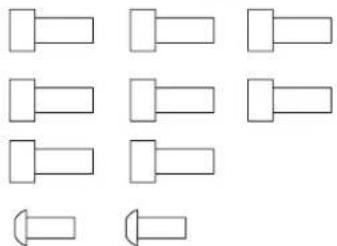
natural_image
Pure geometric shapes including rectangles and a dot, without any text, numbers, or symbols.(47) M6x14mm Allen Head Cap Screw,8pc.
(50) M5x14mm Phillips Head Screw,2pc.
STEP6
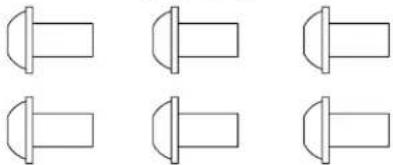
natural_image
Six identical line drawings of a mechanical component with flanges and cylindrical ends (no text or symbols)(44) M8x16mm Button Head Cap Screw,6pc.
(45) M8 Washer,6pc.
STEP8
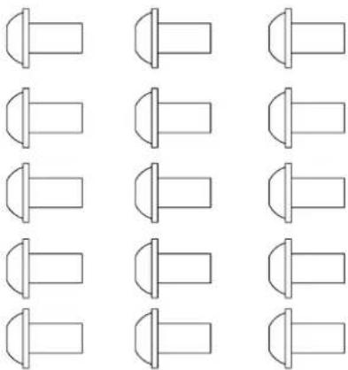
natural_image
Grid of identical mechanical component outlines arranged in three rows (no text or symbols)(44) M8X16mm Button Head
Cap Screw,16pc.
(45) M8 Flat Washer, 16pc.
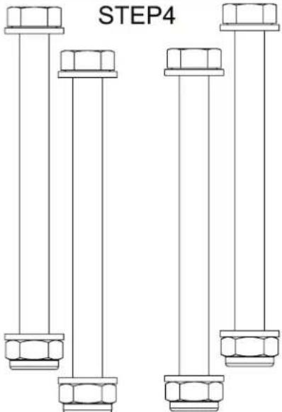
(41) M10x115mm Hex Bolt,4pc.
(42) M10 Locknut,4pc.
(43) M10 Flat Washer,8pc.
STEP9
natural_image
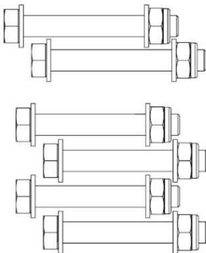
Technical line drawing of four identical mechanical shaft components with bolts and fasteners (no text or symbols)(44) M8x16mm Button Head
Cap Screw,1pc.
(45) M8 Flat Washer,1pc.
(39) M10X75mm Hex Bolt,2pc.
(78) M10X70mm Hex Bolt,4pc.
(43) M10 Flat Washer, 16pc.
(42) M10 Locknut,8pc.
(46) M6X75 Allen Head
Cap Screw, 1pc.
(48) M6 Flat Washer,2pc.
(49) M6 Locknut,1pc.
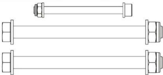
(74) M10X125mm Hex Bolt,2pc.
natural_image
Technical line drawing of two parallel bolts with hexagonal end caps (no text or symbols)
SF5(GM6970-05)3-3
ASSEMBLY INSTRUCTIONS
STEP 1
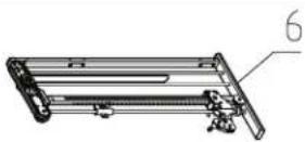
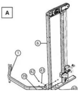
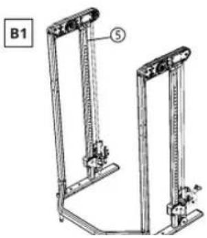
A. Make sure any packing material or supports are removed from the frames prior to assembly. Start by placing the Right Main Frame (6) in the vertical position. Having a second person to hold the frame is helpful or you can possibly lean the frame against a wall. Insert two M10x75mm Hex Bolts (39) through the bottom Lower Crossbar (1) into the back of the Right Main Frame (6), using M10 Flat Washers (43) on both sides and M10 Locknuts (42) hand tightened. Next insert two M10x90mm Hex Bolts (40) into the side of the bottom Lower Crossbar (1) and Right Main Frame (6), using M10 Flat Washers (43) on both sides and M10 Locknuts (42) hand tightened.
B. Place the Left Main Frame (5) in the vertical position and align it with the lower rear Lower Crossbar (1). Insert the hardware as described in the step above.
C. Repeat the steps above to attach the Upper Crossbar (2) to the Right and Left Main Frames (6) (5) similar to the lower Lower Crossbar (1) steps.
SFS
STEP 2
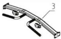
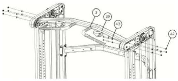
Place the Pull-up Crossbar (3) in position between the two main frames and insert four M10x75mm Hex Bolts (39) with M10 Flat Washers (43) through each main frame. Place M10 Flat Washers (43) and M10 Locknuts (42) onto the bolts.
STEP 3
Lock the sliding carriages on the lowest (number 1) position. Place the Smith Bar (4) in between the rail slide mounts of the frame. Make sure the through hole on the tabs of the bar is positioned as shown. Insert the Smith Bar Pins (22) through both the Right, Left Smith Bar Sliders (60), (62) and into either end of the Smith Bar (4). Use four M6 Allen Head Screws (47) on both sides to secure the Smith Bar Pins (22) to the Smith Bar Sliders (60), (62). Next place the plastic Smith Bar End Caps (37) over the Smith Bar Pins (22) and secure with one MSx14mm Phillips Head Screw (50) per side. Make sure the machine is on level ground and proceed to tighten all hardware installed in steps 1-3. Adjust the two rear feet if needed to level the machine after tightening the hardware.
STEP 4
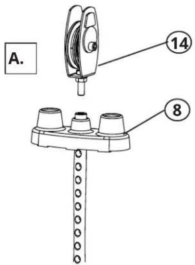
A. Thread the Weight Stack Pulley (14) into the top of both the Top Plate Assembly (8), leave about a 14 inch of thread.
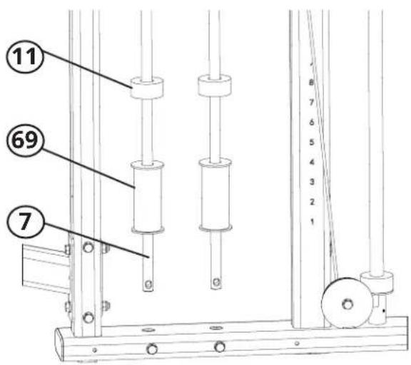
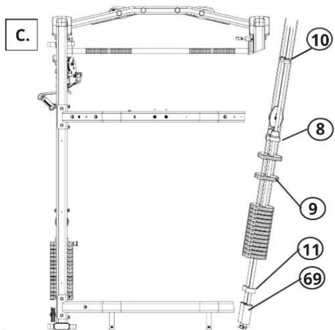
B. Insert the Weight Stack Guide Rods (7) through the holes in the bottom of the frame. Be sure the ends of the rods with the holes are facing down, and do your best to align them with the holes in the frame. Then slide one Weight Stack riser (69) and one Rubber Bumper (9) down each of the guide rods.
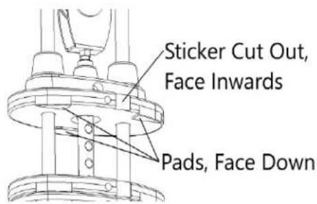
C. Let the the Weight Stack Guide Rods (7) rest at an angle in the frame. Using the provided lubricant, spread the liquid up and down the guide rods. Then slide on 15 Weight Stack Plates (9) with the sticker cut out facing towards the inside of the machine and the protruding pads on the weights facing downward. Next slide on the Top Plate Assembly (8) assembly. Slide on the Guide Rod Bushings (10), one on each rod, the tapered end of the bushing points downward. Repeat this step for the opposite side.
Pg. 12 V09222023
STEP 4 (Continued)
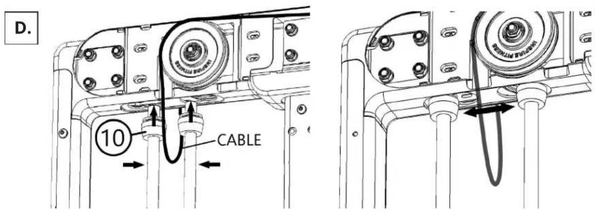
D. Make sure the cable that runs from either side of the frame is positioned between the two guide rods. Carefully pull the guide rods toward each other, then slide the Guide Rod Bushings (10) up into the larger hole of the frame until the slot of the bushing is resting in the frame. Next pull the bushings along with the rods away from each other so that the bushings slide into the smaller hole of the frame, thus locking them in place. The guide rods should be parallel to one another at this point.
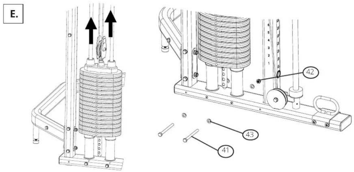
E. Slide the Weight Stack Guide Rods (7) up so that the holes in the bottom of the rods align with the holes in the bottom of the frame. Insert two M10x115mm Hex Bolts (41) with M10 Flat Washers (43) through the frame and holes in the bottom of the rods. Place M10 Flat Washers (43) and M10 Locknuts (42) onto the bolts and tighten them. Repeat this step for the opposite side.
STEP 5
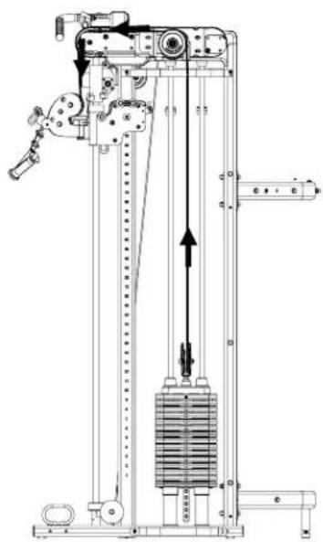
A. Route the cable as shown. Remove the pulley from the Weight Stack Pulley (14) assembly in order to route the cable into it, leave the hardware loose.
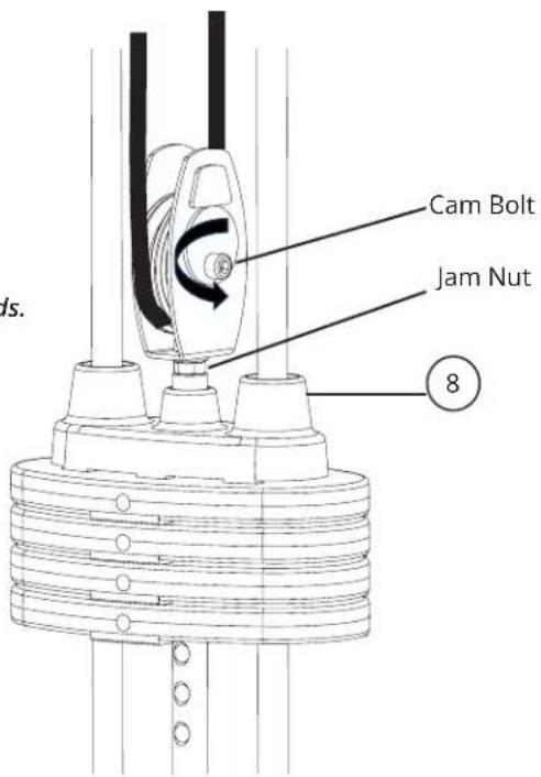
B. Adjust the cable tension by rotating the cam bolt until the Top Plate Assembly (8) starts lifting slightly from the weight stack. Tighten the nut of the cam bolt to lock its position. Then tighten the jam nut at the base of the pulley.

natural_image
Technical line drawing of a mechanical device with vertical and horizontal components, no visible text or symbols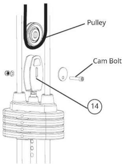

Position the pulley to be perpendicular to the guide rods.
STEP 6
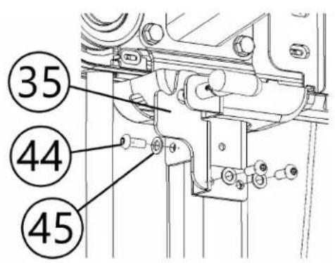
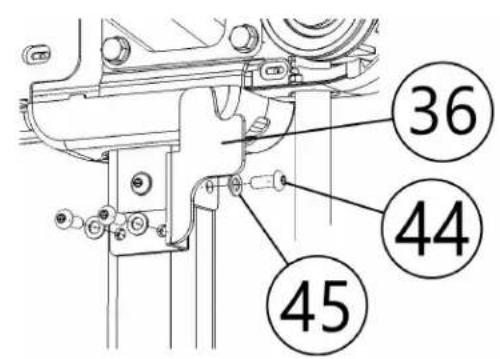
Bolt the smith bar hooks to each side of the main frames. The Right Smith Bar Hook (35) is the mount with the locking pin, the Left Smith Bar Hook (36) is the mount without the pin. Use three M8x16 Buttonhead Cap Screws (44) with M8 Washers (45) per hook to attach to them to the frame as shown.

WARNING
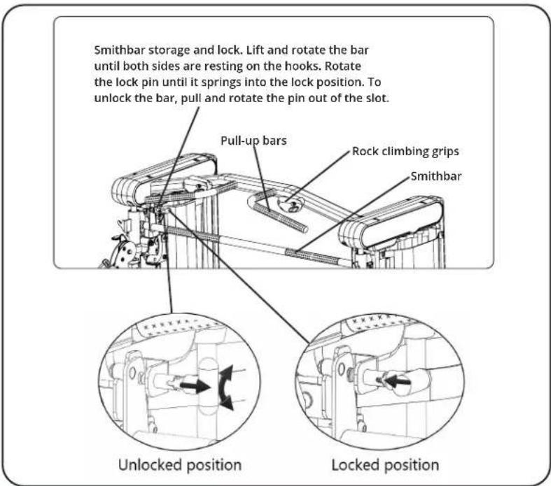
Securely lock the Smith Bar in the storage position whenever it is not in use. Be sure to use the lock pin.
STEP 7
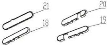
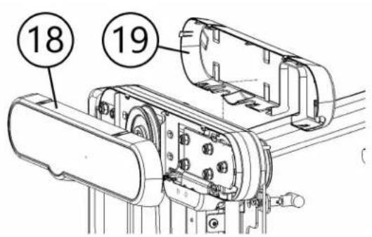
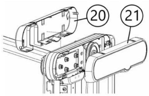
Install the Outer Right Plastic Cover (18), and Inner Right Plastic Cover (19) as shown. Carefully align and press on the covers until they clip into place. Repeat this step with the Outer Left Plastic Cover (21) and Inner Left Plastic Cover (20).
Right Side Left Side
STEP 8
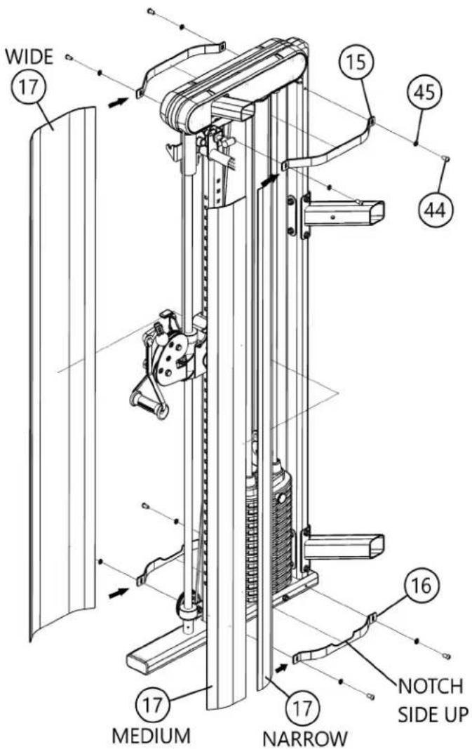
There are three different widths of weight stack shrouds. The widest Shroud (17) is placed on the outside facing part of the weight stack, the Medium (17) and Narrow (17) width shrouds are placed together on the inside, with the smaller placed toward the back of the machine. The mounting plates for them will be marked identifying the Top Shroud Plate (15), Bottom Shroud Plate (16) and the forward direction of them, slide the plates through the pockets of the shrouds. Before applying the inner shrouds, apply the weight plate stickers. The number 1 sticker will go on the top plate, but we recommend that you start with the number 2 sticker. Place the number two sticker on the first weight plate. Then, apply the number 1 to the top weight plate assembly, using the #2 sticker to align it properly. Finish applying the stickers through #16. Secure the weight shrouds with M8 x 16mm Button Head Cap Screw (44) with M8 Washers (45) through the mount plates to the frame.
STEP 9
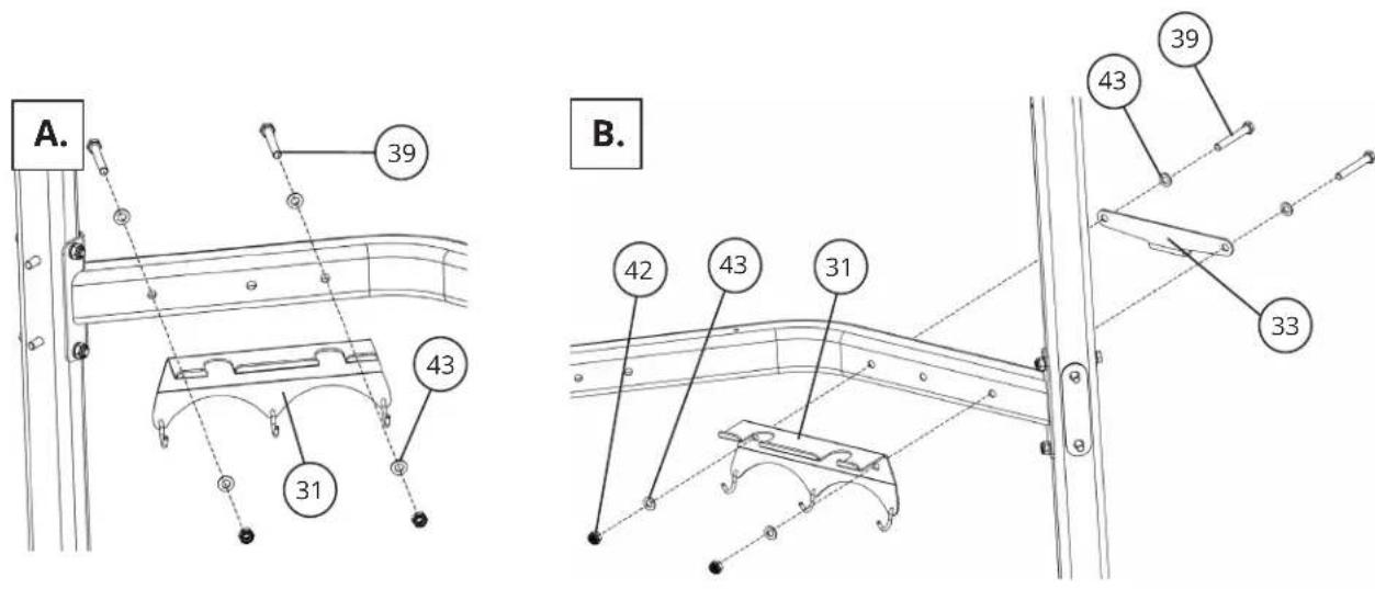
A. Place the Accessory Rack (31) on right side of the Upper Crossbar (2). Insert two M10 x 75mm Hex Bolts (39) with M10 Flat Washers (43) through the rack and crossbar. Place M10 Flat Washers (43) and M10 Locknuts (42) onto the bolts. Tighten the hardware.
B. Place the Accessory Rack #2 (31) on Left side of the Inside of the Upper Crossbar (2). On the back side of the tube, Place the Bench Mount (33) Insert two M10 x 75mm Hex Bolts (39) with M10 Flat Washers (43) through the rack and crossbar. Place M10 Flat Washers (43) and M10 Locknuts (42) onto the bolts. Tighten the hardware.
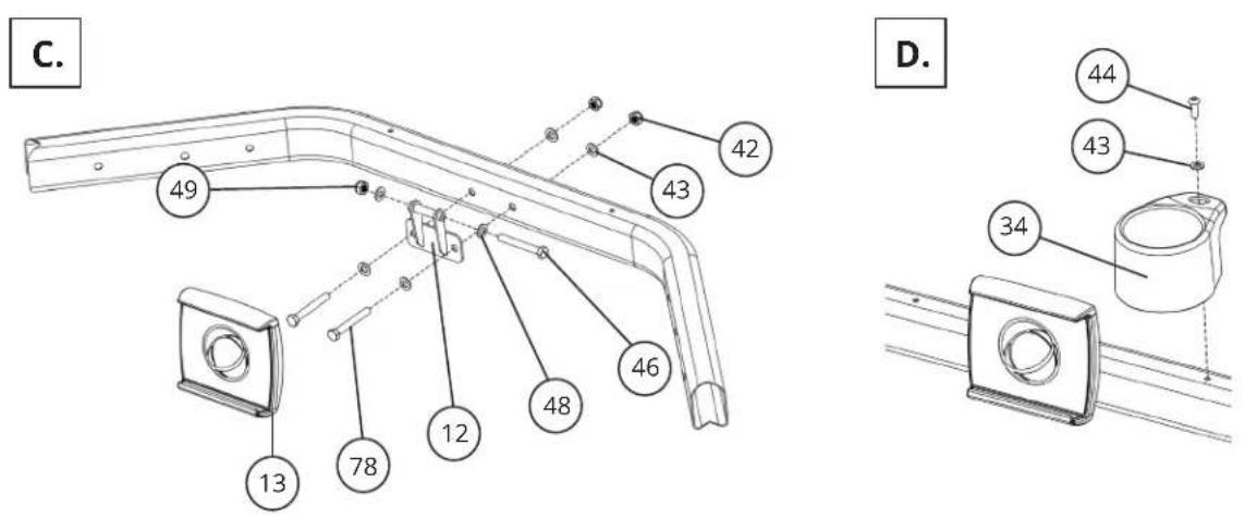
C. Mount the Tablet Mount (12) in the middle of the Upper Crossbar (2). Insert two M10 x 75mm Hex Bolts (39) with M10 Flat Washers (43) through the mount and Upper Crossbar (2). Place M10 Flat Washers (43) and M10 Locknuts (42) onto the bolts, tighten the hardware. Place the Tablet Holder on to its mount and secure with a M6x75mm Allen Head Cap Screw (46) and M6 Locknut (49), using M6 Washers (48) on both sides. Tighten hardware until tablet holder holds its position but can still be tilted up and down by hand. Note: The Tablet holder mount can be bolted up or down depending on if you want the tablet holder higher or lower.
D. Place the Cup Holder (34) on the left side Upper Crossbar (2), insert one Bolt (44) with a Flat Washers (43) through the hole to fasten in place.
©INSPIRE
STEP 9 (Continued)
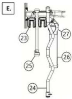
E. Place the 5 Lb Add On Weights (23), Dual Hook Curl Bar (24), Triceps Rope (25), Chin/Dip Belt (26), and Ankle Strap (27), on the accessory racks as shown.
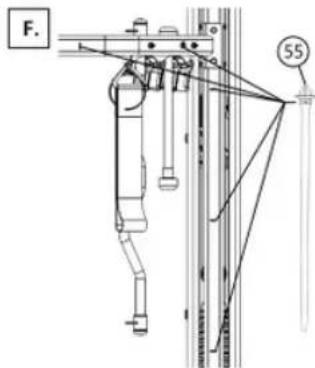
F. Optional: If you have electronics with cords, you can use the included Cable Clips (55) to route the cables along the frame of the machine
IMPORTANT: Before use
Remove bolts with labels that read "REMOVE BEFORE USE". Located one per side as indicated. This will allow the carriage counterweights to move freely.
FEATURES AND FUNCTIONS

WARNING
Securely lock the Smith Bar in the storage position whenever it is not in use. Be sure to use the lock pin.
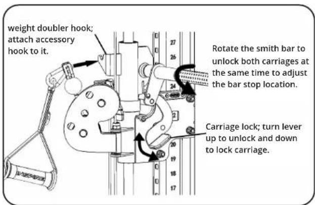
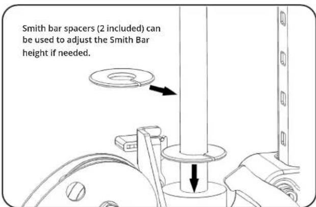
LABEL PLACEMENT
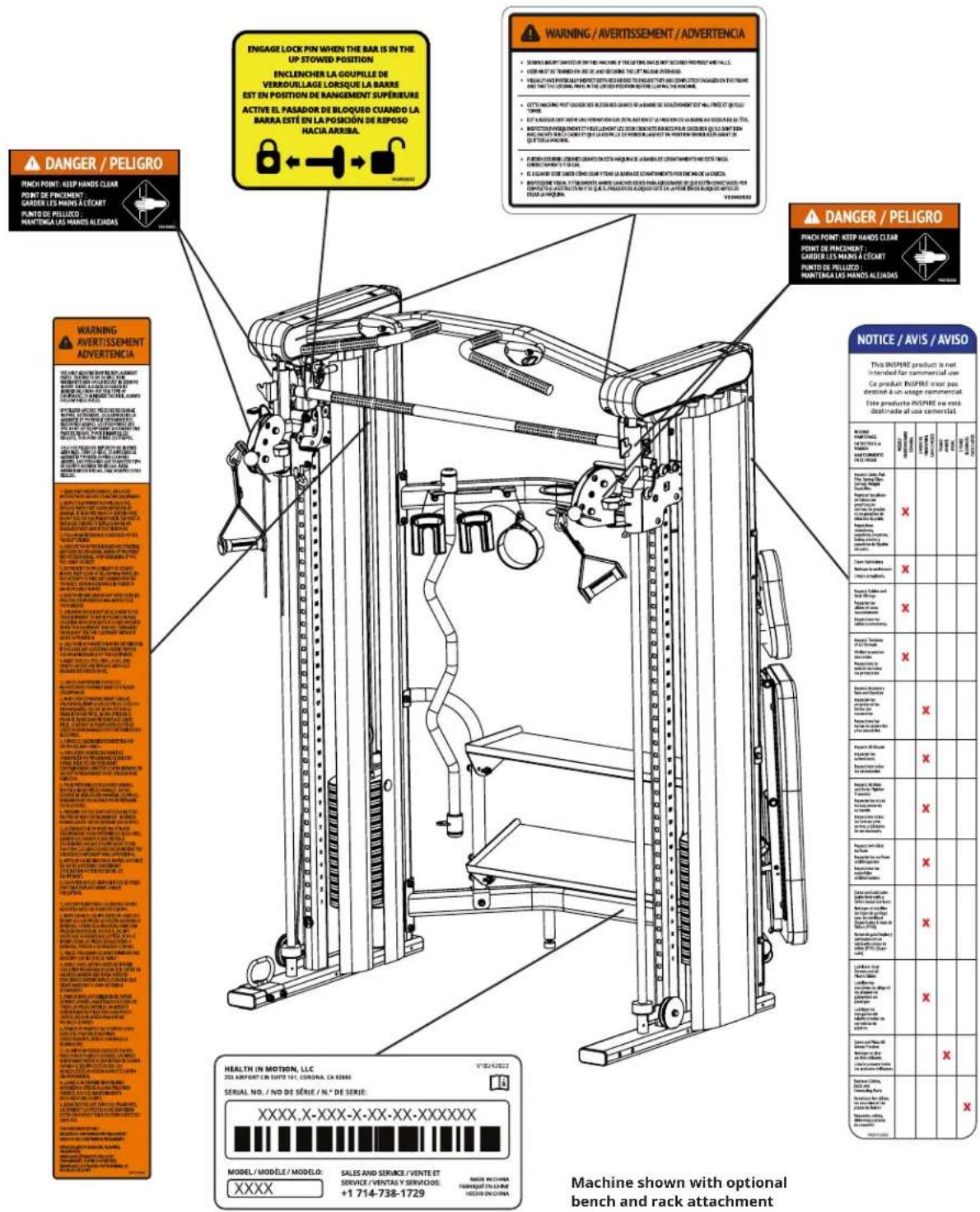
LIVE AREA
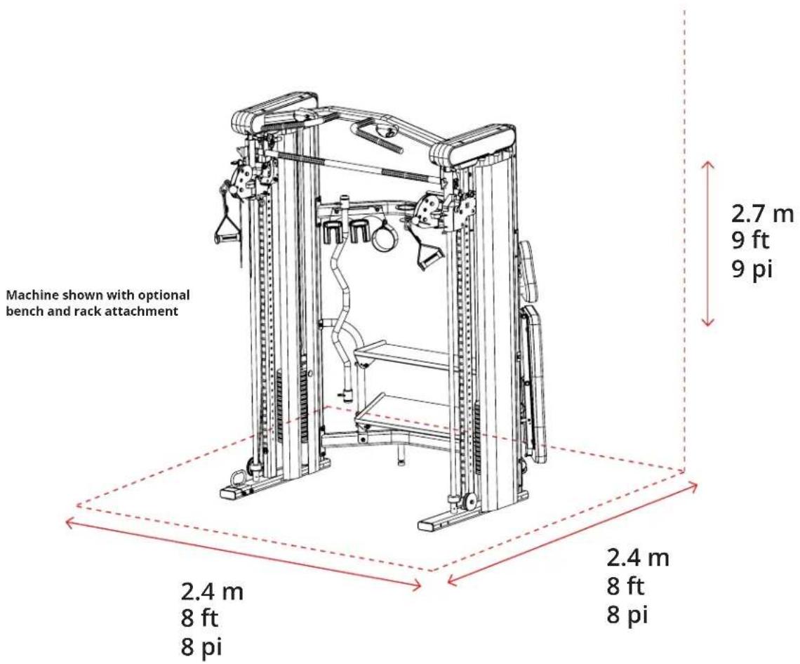
PRODUCT DIMENSIONS
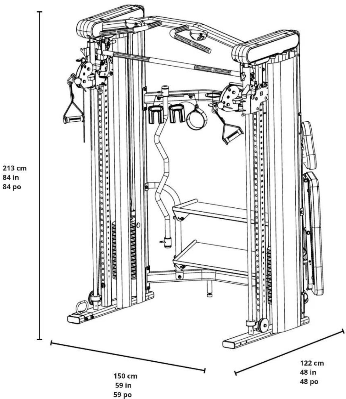
Machine shown with optional bench and rack attachment
MAINTENANCE
Warning
DO NOT place styrofoam or printed materials on the seat pads. Over time, these may stick to the pads and mar the surface.
DO NOT leave items sitting on the seat pads, these pads have a special density that takes shape to objects and small objectswill leave imprints in the surface that may take time to come out.
• Periodically inspect the cables for splitting, cracking or fraying. Also watch for bulging or flat areas in the cable. Pay particular attention to the cable ends.
• Immediately replace cables at the first signs of damage or wear. Never use equipment with damaged or worn cables.
- Cables naturally stretch over time, so check cable slack periodically and adjust cable tension as needed.
- Regularly inspect product for loose hardware.
- Do not use or store equipment outdoors.
- Inspect snap links, swivels, handles and weight stack pin for wear or damage. If wear or damage exists, replace with Inspire Fitness parts only.
- Locate and familiarize yourself with all warning decals on the Smith Machine Functional Trainer.
- Replace damaged or worn upholstery immediately.
• Periodically wipe down guide rods with a dry cloth and re-apply a thin coat of a Teflon™ based lubricant.
EXPLODED VIEW
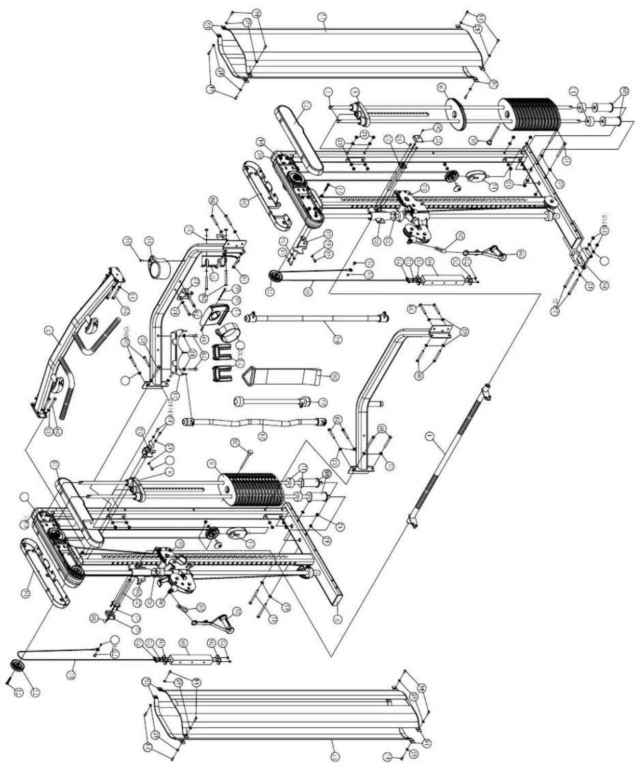
PARTS LISTS
| No. Description Part Number Qty. | |||
| 1 | GM697260001PZ Lower Crossbar 1 | ||
| 2 | GM697260002PZ01 Upper Crossbar 1 | ||
| 3 GM | 697220003PZ Pull-up Crossbar 1 | ||
| 4 | GM697320004PZ01 Smith bar 1 | ||
| 5 GM | 697200010PZ Left Main Frame 1 | ||
| 6 GM | 697200011PZ Right Main Frame 1 | ||
| 7 GM | 697501001WX Weight Stack Guide Rods 4 | ||
| 8 GM | 692500003PZ14 Top Plate Assembly 2 | ||
| 9 GM | 692-500-009 Weight Stack Plate 30 | ||
| 10 GM | 692-881-002 Guide Rod Bushings | 4 | |
| 11 GM | 692-881-003 Rubber Bumper | 4 | |
| 12 GM | 697260007PZ Tablet Mount | 1 | |
| 13 BC | 423880109PZ05 Tablet Holder | 1 | |
| 14 GM | 692500002PZ04 Weight Stack Pulley | 2 | |
| 15 GM | 697321037PT0105 Top Shroud Plate | 4 | |
| 16 GM | 697321036PT0105 Bottom Shroud Plate | 4 | |
| 17 GM | 697-800-001 Wide, Medium, and Narrow Shrouds 2 | ||
| 18 GM | 697-881-003 Outer Right Plastic Cover | 1 | |
| 19 GM | 697-881-004 Inner Right Plastic Cover | 1 | |
| 20 GM | 697-881-005 Inner Left Plastic Cover | 1 | |
| 21 GM | 697-881-006 Outer Left Plastic Cover | 1 | |
| 22 GM | 697320007PZ Smith Bar Pin | 2 | |
| 23 GM | 692-500-001 5 Lb Add-on Weight 2 | ||
| 24 GM | 691320003PZ02 Dual Hook Curl Bar | 1 | |
| 25 GM | 692-881-011 Triceps Rope | 1 | |
| 26 GM | 692-400-005 Chin/Dip Belt | 1 | |
| 27 GM | 690-880-002 Ankle Strap | 1 | |
| 28 GM | 697-561-018 Spring Clip | 2 | |
| 29 GM | 870-880-007SK Single Handle | 2 | |
| 30 GM | 697500003PZ Wire Rope Assembly | 2 | |
| 31 GM | 697260004PZ01 Accessory Rack | 1 | |
| 32 GM | 697-881-010RC Smithbar spacers | 2 | |
| 33 GM | 697381008PZ Bench Mount | 1 | |
| 34 GM | 697-881-011 Plastic cup holder | 1 | |
| 35 GM | 697320008PZ Right Smithbar hook | 1 | |
| 36 GM | 697321018PZ Left Smithbar hook 1 | ||
| 37 GM | 697881007RCPZ Smith Bar End Caps 2 | ||
| 38 GM | 692500004PZ Weight Pin | 2 | |
| 39 011 | 1-010-758 M10X75 mm Hex Bolt | 17 | |
| 40 011 | 1-010-908 M10X90 mm Hex Bolt | 8 | |
| No. | Description Part Number Qty. | |||
| 41 01 | 1-010-058 | M10X115 mm Hex Bolt | 4 | |
| 42 01 | 0-710-008 | M10 Locknut | 33 | |
| 43 01 | 6-010-008 | M10 Flat Washer | 66 | |
| 44 01 | 3-208-168A M8x16mm Button Head Cap Screw | 23 | ||
| 45 01 | 6-008-028 | M8 Washer | 22 | |
| 46 | 0113-206-751 | M6X75 Allen Head Cap Screw | 1 | |
| 47 01 | 3-706-142 | M6x14mm Allen Head Cap Screw | 8 | |
| 48 01 | 6-006-019 | M6 Flat Washer 2 | ||
| 49 01 | 0-706-019 | M6 Locknut | 1 | |
| 50 | 0113-105-148 | M5x14mm Phillips Head Screw | 2 | |
| 51 05 | 1-608-002 | 8# | Allen Tool | 1 |
| 52 AB | 290-561-002 | 5# | 80*30, Multi Tool | 1 |
| 53 | M330-561-002 | 14# & 17# Hex Wrench | 2 | |
| 54 AB | 160561002XWX | 10# | Allen Tool | 1 |
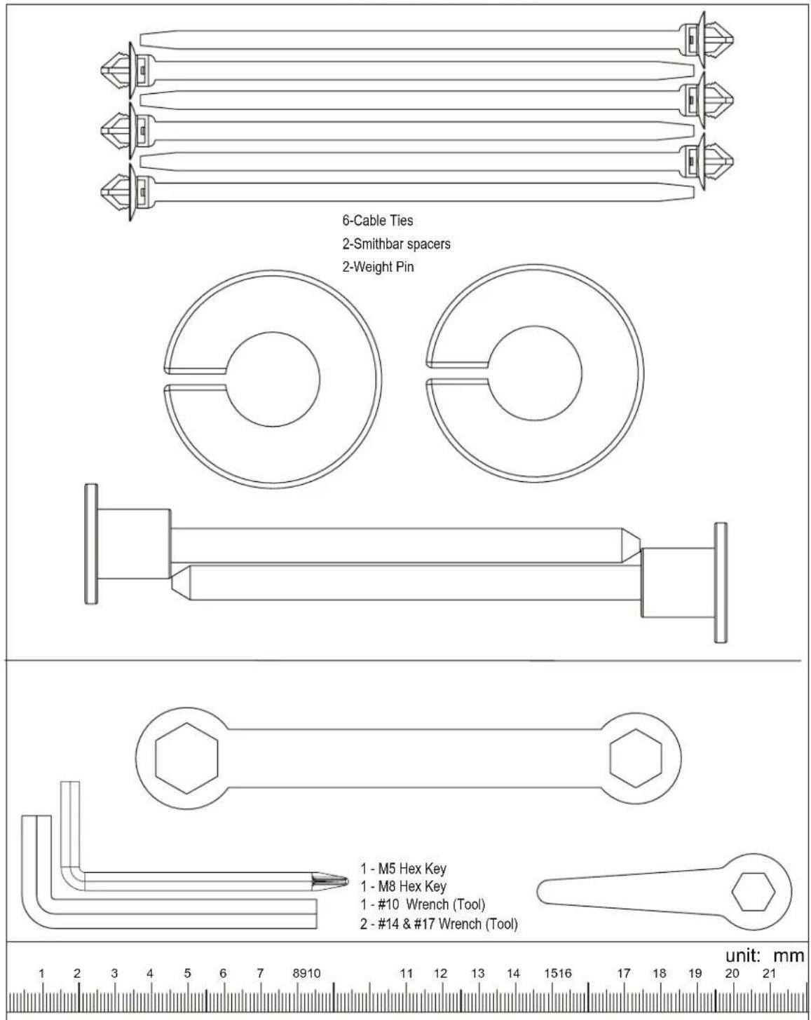
| 55 | GM697-891-102 | Cable Tie | 6 | |
| 56 GM | 697580004PZ | Hardware Pack 1 | 1 | |
| 57 GM | 697580005PZ | Hardware Pack 2 | 1 | |
| 58 GM | 697580006PZ | Hardware Pack 3 | 1 | |
| 59 | GM697320013PZ | Right Carralge Assembly | 1 | |
| 60 GM | 697320006PZ | Right Smith Bar Slider | 1 | |
| 61 GM | 697320014PZ | Left Carralge ssembly | 1 | |
| 62 GM | 697320005PZ | Left Smith Bar Slider | 1 | |
| 63 GM | 697-881-001 | Inner trim cover R | 2 | |
| 64 GM | 697-881-002 | Inner trim cover L | 2 | |
| 65 GM | 691320004PZ03 | Straight Bar | 1 | |
| 66 GM | 697300001PZ | Battle rope mount | 1 | |
| 67 GM | 697-500-001 | Cable | 2 | |
| 68 GM | 697561011PT0105 | Counter weight | 2 | |
| 69 GM | 692380001PT0105 | Risers | 4 | |
| 70 GM | 697-881-015 | Counter weight slider | 4 | |
| 71 01 | 3-210-558A | M10*55 Buttonhead Cap Screw | 2 | |
| 72 01 | 6-310-028 | Spring washer | 6 | |
| 73 | 0113-306-128A | Hexagon socket countersunk head screw | 8 | |
| 74 01 | 1-010-122 | M10*125 Hex Bolt | 2 | |
| 75 GM | 695-561-016 | Nut | 4 | |
| 76 GM | 695-561-017 | Buttonhead Cap Screw | 4 | |
| 77 GM | 692-880-001 | Pulley | 12 | |
| 78 01 | 1-010-708 | M10X70 mm Hex Bolt | 4 | |

INSPIRE
www.inspirefitness.com
- CONGRATULATIONS
- BEFORE ASSEMBLING YOUR SF5
- CONTACT US FOR HELP
- Phone
- Chat
- TABLE OF CONTENTS
- PRODUCT WARRANTY
- AUSTRALIA
- IMPORTANT SAFETY NOTICE
- PRECAUTIONS
- Care and Maintenance
- ASSEMBLY AND SETUP
- Package Contents
- Assembly Hardware Kit (Not to Scale)
- SF5(GM6970-05)3-2
- ASSEMBLY INSTRUCTIONS
- STEP 1
- STEP 2
- STEP 3
- STEP 4
- STEP 4 (Continued)
- STEP 5
- STEP 6
- WARNING
- STEP 7
- STEP 8
- STEP 9
- ©INSPIRE
- STEP 9 (Continued)
- IMPORTANT: Before use
- FEATURES AND FUNCTIONS
- LIVE AREA
- PRODUCT DIMENSIONS
- MAINTENANCE
- EXPLODED VIEW
- INSPIRE
Brand : INSPIRE
Model : SF5
Category : Fitness Equipment