Apache RR 310 BTO - Motorcycle TVS - Free user manual and instructions
Find the device manual for free Apache RR 310 BTO TVS in PDF.

| Product Type | Motorcycle |
| Brand | TVS |
| Model | Apache RR 310 BTO |
| Engine Type | Single-cylinder, 4-stroke, liquid-cooled |
| Displacement | 312.2 cc |
| Fuel System | Electronic Fuel Injection (EFI) |
| Max Power | 34 hp @ 9,700 rpm |
| Max Torque | 27.3 Nm @ 7,700 rpm |
| Transmission | 6-speed manual |
| Front Brake | 300 mm disc with ABS |
| Rear Brake | 240 mm disc with ABS |
| Front Suspension | USD forks, 41 mm |
| Rear Suspension | Monoshock, adjustable |
| Dimensions (L x W x H) | 2001 mm x 785 mm x 1135 mm |
| Seat Height | 810 mm |
| Wheelbase | 1365 mm |
| Weight (Kerb) | 174 kg |
| Fuel Tank Capacity | 11 liters |
| Electrical System | 12V, battery powered |
| Lighting | Full LED headlight and taillight |
| Instrument Cluster | Digital with Bluetooth connectivity |
| Maintenance Interval | Every 6,000 km or 6 months |
| Spare Parts Availability | Authorized TVS service centers |
| Safety Features | Dual-channel ABS, side-stand engine cut-off |
Frequently Asked Questions - Apache RR 310 BTO TVS
User questions about Apache RR 310 BTO TVS
0 question about this device. Answer the ones you know or ask your own.
Ask a new question about this device
Download the instructions for your Motorcycle in PDF format for free! Find your manual Apache RR 310 BTO - TVS and take your electronic device back in hand. On this page are published all the documents necessary for the use of your device. Apache RR 310 BTO by TVS.
USER MANUAL Apache RR 310 BTO TVS
natural_image
Black and silver F-55 motorcycle with sleek design against dark background (no visible text or symbols)Owner's Manual


Revision:- Rev. 5, 28th April 2023 onwards
FOREWORD
TVS Racing
Dear Racer,
Thank you for choosing the TVS Apache RR 310. The most powerful and technologically advanced Apache yet.
The precision racer has been shaped in the wind tunnel, honed on the dyno and perfected over countless laps on the racetrack. The flagship racer is the culmination of the TVS Racing heritage since it's inception in 1982. The racing prowess reflects in every straight line and ever corner of the track. The Apache RR 310 has been crafted to be the ultimate racer.
This manual explains the features and operations of your TVS Apache RR 310. Please read it carefully and follow the instructions to enjoy the racing experience.
To prolong your journey on the TVS Apache RR 310, we urge you to get your TVS Apache RR 310 services only at TVS Motor Company Authorized Dealers.
Here's to breaking lap records on your Apache RR 310.
TVS Motor Company Limited
Brand Experience
Live the pure performance life.
Since 2005, TVS Apache has been at the helm of performance motorcycling, creating an entirely new breed of racers. And now that you have chosen the ultimate race machine, you are also part of this esteemed legacy. Not just that, you are also standing at the portal to a 360 moto-experience encompassing from out riding your limits at the racetrack to becoming part of a league of riders who share your passion for motorcycling.
Apache Owners Group
Join the league of Apache motor enthusiasts that share your passion for riding. Explore the unchartered, tame every terrain, forge unbreakable bonds, and make unforgettable memories with every journey.
Go on thrilling rides all year round –
Breakfast ride | Overnight ride | Marquee ride | Chapter ride
Apache Racing Experience
If you have the mettle, we have the track. Apache Racing Experience (ARE), a flagship property of TVS Racing & Apache, is the embodiment of our philosophy, "the bikes we race are the bikes we sell." Hone your racing skills and techniques with the INMRC Champion riders from TVS Racing and test the limits of your machine and yourself.
TVS Racing Training School
Founded in 2017, TVS Racing Training School aims at fostering motor sports in India. We believe that all our riders are racers at heart and here, they can unleash that racer and learn the skills under National Champions. And through multiple levels of training, we hope to turn these racing zealots into the podium winners of tomorrow.
Join the AOG community - https://www.tvsapache.com/assets/pdf/AOG-Regulations.pdf and also download the TVS Connect app / https://www.tvsapache.com/aog.aspx

TVS Racing PERFORMANCE GEAR
PERFORMANCE GEAR
When you ride your performance machine, you need to have gear that performs too. That's why we have TVS Racing Performance Gear – an entire range of riding gear designed to offer you the ultimate riding experience. With utmost safety and extreme comfort, it lets you take on every terrain and any weather.
With the range of urban wear, you can wear your passion even off track. And the racing DNA woven in is all you need to get your podium look on.
Riding Jackets & Pants | Helmets | Riding Boots | Riding Gloves Polo T-Shirts | Caps | Sunglasses | Backpacks
To know more log on to - https://accessories.tvsmotor.com/performance-gear.aspx

OUR RACING HERITAGE IS NOW YOURS TO TAKE FORWARD
Your TVS Apache is born of the legacy of TVS Racing

TVS Racing
Incase you need any Clarification please contact above Dealer
Or
TVS Motor Company's Area Offices (flip over for addresses)
Or
Toll Free Number : 1800-258-7111
Email : customercare@tvsmotor.com
Disclaimer : TVS Motor Company or any of its officials / Authorized Main dealer / Authorized Dealer do not ask customers for bank / card / wallet details / authentication. In case you face any such claim, please report to the relevant local authorities immediately.
CONTACT AT OUR AREA OFFICES
TAMILNADU-1, 3 & 4
1. TVS Motor Company Limited
V Floor, Gee Gee Universal,
No. 2, MC Nichols Road,
Chetpet, Chennai - 600 031.
Phone : 044-28361651/28361654
Email: AO.Chennai@tvsmotor.com
AO.Madurai@tvsmotor.com
TAMILNADU-2
2. TVS Motor Company Limited
No. 10, 2nd floor,
Shree Shanmugapriya Towers,
Kannuswamy Street,
Behind Hotel Annapoorna,
R S Puram, Coimbatore - 641 002.
Phone: 0422-4350060/2541035
Email: AO.Coimbatore@tvsmotor.com
KERALA
3. TVS Motor Company Limited
Ambady Towers, Second Floor,
Door No. 27/631, A6,
Edappally-Pookkattupady Road,
Edappally PO., Cochin - 682 024.
Phone: 0484-2544578/2556938
Email: AO.Cochin@tvsmotor.com
KARNATAKA-1, 2 & GOA
4. TVS Motor Company Limited
No. 600, Anand Surya, 2nd Floor,
15th Cross, 6th Phase, JP Nagar,
Opp. BMTC Bus Stop,
Bangalore - 560 078.
Phone: 080-26653433
Email : AO.Bangalore@tvsmotor.com
ANDHRAPRADESH & TELANGANA
5. TVS Motor Company Limited
Rukumani Towers, First Floor,
No. 3-11-30, Plot No. 11,
Paigha Colony, Behind Anand Theater,
Secunderabad - 500 003.
Phone : 040-27840590/27844419
Email : AO.Hyderabad@tvsmotor.com
AO.Vijayawada@tvsmotor.com
MAHARASHTRA-1 & 2
6. TVS Motor Company Limited
No. 401, 4th Floor, The Chambers,
Plot No. 4/12/3, Near Ganapati Chowk,
Viman Nagar, Pune - 411 014.
Phone : 020-26632112/26632110
Email : Service.pune@tvsmotor.com
MAHARASHTRA-3 & CHATTISGARH
7. TVS Motor Company Limited
No. 502B, 6th Floor, B Wing,
Shriram Shyam Towers,
Near LIC Square, Sardar,
Nagpur - 440 001.
Phone:0712-2569932
Email: Service.Nagpur@tvsmotor.com
AO.Raipur@tvsmotor.com
GUJARAT
8. TVS Motor Company Limited
1208-1213, Shivalik Satyamev,
Below Bopal Over Bridge,
Ambli-SP Ring Road Junction, Bopal,
Ahmedabad- 380 058.
9. TVS Motor Company Limited
No. 211-212, 2nd Floor,
Chinar Incube Business Centre,
Chinar Fortune City,
Near Brindhavan Dhaba,
Hosangabad Road,
Bhopal - 462 026.
Phone : 0755-2499406/2499306
Email: AO.Bhopal@tvsmotor.com
AO.Indore@tvsmotor.com
RAJASTHAN-1 & 2
10. TVS Motor Company Limited
Plot No. 17-18,
2nd Floor of National Motors Building,
Jhotwara Industrial Area,
Jaipur - 302 012.
Phone: 0141-5150901/5150902
Email : AO.Jaipur@tvsmotor.com
AO.Udaipur@tvsmotor.com
DELHI & HARYANA
11. TVS Motor Company Limited
D-3 & D-4, 2nd Floor,
Sector - 10, Noida,
Uttar Pradesh - 201 301.
Phone : 011-29834640/29834773
Email : AO.Delhi@tvsmotor.com
PUNJAB & CHANDIGARH
12. TVS Motor Company Limited
4th Floor, Royal Business Park,
Chandigarh Ambala Highway,
Zirkapur - 140 603.
Phone: 01762-464777/465777
Email: AO.Chandigarh@tvsmotor.com
UTTAR PRADESH WEST
13. TVS Motor Company Limited
D-3 & D-4, 2nd Floor,
Sector - 10, Noida,
Uttar Pradesh - 201 301
Phone: 011-29834640/29834773
Email : AO.Delhi@tvsmotor.com
UTTAR PRADESH CENTRAL & EAST
14. TVS Motor Company Limited
1st Floor, Cyber Tower, TC-34/V-2,
Vibhuti Khand, Gomti Nagar,
Lucknow - 226 010.
Phone : 0522-4918300/4918301
Email : AO.Lucknow@tvsmotor.com
WEST BENGAL
15. TVS Motor Company Limited
Ground Floor & First Floor,
133 A. S. P. Mukherjee Road,
Opp. Tollygunge Police Station,
Kolkata - 700 026.
Phone:033-24617096/24617092
Email : AO.Kolkata@tvsmotor.com
BIHAR
16. TVS Motor Company Limited
N-Plaza, Jamal Road,
P.S. Kotwali,
Patna - 800 001
Phone: 0612-2200068/2200069
Email: AO.BNJ@tvsmotor.com
TVS Racing
ORISSA & JHARKHAND
17. TVS Motor Company Limited
No. 303, 3rd Floor,
Creative Plaza, Rasulgarh,
Bhubaneshwar - 751 010.
Phone: 0674-2580019
Email: AO.Bhubaneshwar@tvsmotor.com
NORTH EAST STATES
18. TVS Motor Company Limited
147, Udayan, Ganesh Guri,
Near Hotel D Courtyard,
R G B. Road, Guwahati - 781 005.
Phone : 0361-2202030/2202031
Email: AO.Guwahati@tvsmotor.com
INTRODUCTION
TVS Racing
TVS Motor Company Limited advices you to read this manual carefully in order to familiarise yourself with your motorcycle. In case of any clarification, please contact any of our Authorised Main Dealer.
This manual contains important information about controls and operation, technical features, maintenance and care to be taken to keep your vehicle reliable and safe. We recommend that you strictly follow the instructions in this manual, especially those regarding the running-in period and periodic maintenance.
TVS Motor Company Limited declines any liability whatsoever for any mistakes incurred during the development of this manual. All the information in this manual is valid at the time of publication.
TVS Motor Company Limited reserves the right to make any modifications required due to the ongoing development of their products. In such events it is possible that the relevant part of this Owner's Manual does not apply to your vehicle.
Prior permission of TVS Motor Company Limited is required for quoting, copying or reproducing any part of this Owner's Manual.
This Owner's manual uses a set of symbols with special meanings. They are:

Warning
Disregarding this message might result in injury to the rider or deadly accidents.

Caution
This message indicates special procedures or precautions to be followed to avoid damage to the vehicle.

Note
This message provides further clarification for clear understanding of any particular information.
TVS Racing
The terms 'LH' and 'RH' are referred to the motorcycle viewed from the riding position.
Accessories shown in the picture may not be the part of standard equipment.
For your safety, as well as to preserve warranty, reliability and road worthy of your motorcycle, use original TVS Motor Company Limited spare parts only.
In order to ensure the reliability of your product, you are strongly advised to refer our Authorised Main Dealers for any service requiring particular technical expertise.
Skilled personals of our Dealer have the tools required to perform any servicing job to the highest professional standards to ensure smooth running and long life of your motorcycle.
TVS Racing
DESCRIPTION PAGE No.
RUNNING-IN INFORMATION 01
SAFE RIDING TIPS 02
Safe Riding Recommendations 02
Maximum Permissible Load 05
ACCESSORY INSTALLATION TIPS 06
KNOW YOUR MOTORCYCLE 07
Anti-Lock Brake System (ABS) 07
EMS a Glance 09
Ride by Wire 10
RT Slipper Clutch 11
Adjustable Suspension 12
Emission Control 13
Vehicle identification number 15
Control Key 16
Location of Parts -
Vehicle RH Side View 17
Vehicle LH Side View 18
CONTROLS & ITS OPERATIONS
Ignition cum Steering Lock 20
Clutch Lever 21
Switch Assembly LH 22
Rear Brake Pedal 28
Switch Assembly RH 29
Throttle Twist Grip 30
Front Brake Lever 31
CONNECTED TFT INSTRUMENT CLUSTER 32
TFT Instrument Cluster 34
TFT Multifunction display 37
Menu Indication 38
Ride Mode 39
Urban Mode 41
Rain Mode 50
Sport Mode 51
Track Mode 52
Trip Details 53
My Vehicle 55
Service 55
Performance Record 56
Documents 60
Preferences 62
Connectivity 62
Display Set Up 65
Custom Widgets 72
Speed Alert 78
TVS Racing
DESCRIPTION PAGE No.
TVS CONNECT APP 80
Major Components 90
Cooling System 93
Fuel Tank Cap 95
Side Stand 97
Adjustable suspension 98
Seat Lock 99
RIDING YOUR MOTORCYCLE 100
Before Riding 100
While Riding 102
Starting the Engine 103
Moving the Vehicle 104
Braking 105
Parking 105
Fuel Recommendation 106
GENERAL ADJUSTMENTS 109
Rear View Mirrors LH & RH 109
Gear Shift Pedal Position 109
Adjustable suspension 111
Head Lamp Aiming 118
Safety Precautions 125
Engine Oil Level 126
Clutch Free Play 128
Brake Fluid Level 130
Brake Pad Wear 131
Rims and Tubeless Tyres 133
Drive Chain 137
Front Wheel 140
Rear Wheel 143
Battery 147
Fuses 149
Mirror Assembly 152
Diagnostic Connector 153
Cleaning your Motorcycle 154
Storage Procedures 155
Restoring the Motorcycle to use 156
Taking Long Trips 157
DESCRIPTION PAGE No.
GENERAL INFORMATION 158
Tool Kit 158
Auxiliary Stand (Paddock Stand) 159
WARRANTY AND SERVICES 162
Warranty Policy 166
Service Information 168
Pre-Delivery Inspection 169
Planned Service Schedule 170
Pickup and drop 171
TECHNICAL SPECIFICATIONS 172
Recommended Fuel and Lubricants 177
Engine 178
Transmission 179
Dimensions 180
Frame and Suspension 181
Wheel and Brakes 182
Free Plays 183
Electricals 184
Important Torque 185
Basic Trouble Shooting 186
GENERAL INFORMATION 183
Running-in Recommendations
Running-in is essential to preserve engine life and performance over time. Twisty roads and gradients are ideal to run in the engine, brakes and suspension effectively. The first 1000 km is a running-in period for your motorcycle.
Maximum engine speed during running-in 0 to 1000 km - below 7000 rpm
During the first 1000 km, avoid the full throttle starts and rapid acceleration, which could expose the engine parts to excessive stress. It is advisable to run the engine at varying load and rpm, though still within recommended rpm limit.
Avoid riding at constant engine rpm for prolonged periods.
During initial running, use brakes gently. Do not brake hard or keep brake applied for too long to enable a correct break-in of brake pad friction material against the brake discs.
To allow all the mechanical parts of motorcycle to adapt each another, and to avoid reduction of engine components life, it is advisable to avoid sudden acceleration and running the engine at high rpm for too long, especially uphill.
Check the drive chain frequently and if required adjust it. Also ensure that the chain is lubricated as required to increase its service life.

Caution
On completion of running -in period, scheduled maintenance service should be observed carefully without fail. Failure to comply with this will result in damage to the engine parts and other key parts of the vehicle or shorter engine life.
Keeping to the running-in recommendations will ensure longer engine life and reduce the need for overhauls and re-tuning.
SAFE RIDING TIPS
TVS Racing
Safe Riding Recommendations
The following points are applicable for every day usage of your motorcycle and should be observed carefully for safe riding of your motorcycle.
Riding skills and your mechanical knowledge forms the foundation of safe riding practices. We suggest you to practice riding your TVS Apache RR 310 in a low-traffic condition until you are thoroughly familiar with your motorcycle and its controls.
Most of the accidents are the result of inexperience of rider. Always make sure you are carrying your driving license with you; you must have a valid license that enables you to ride a motorcycle of this kind. Avoid lending your motorcycle to the persons who are inexperienced and not holding a valid driving license.
A motorcycle is not designed to provide impact protection, so defensive riding in addition to wearing of protective apparel is very important.
Please do not let the protective apparels give you a false sense of security.
Both the rider and the pillion should always wear an ISI approved, comfortable and good quality safety helmet before riding the vehicle. Because, one of the most serious injury that can happen is an head injury.
You should also have a good quality goggles to protect your eyes and help your vision.
Avoid wearing loose clothes or accessories that could become tangled in the controls or limit your field of vision.
Riding at proper speed and avoiding sudden acceleration are not only important for safety and low fuel consumption. It is also important for longer life of vehicle and smoother operation.
Avoid use of mobile phones while riding as it could lead to fatal accident.
To prevent or minimise accident, never consume alcohol or drugs before or during the operation of your vehicle. Even minimal consumption of these will affect the rider's ability to control the vehicle.
Ride within the law and observe national and local rules. Always respect speed limits. However, adjust your speed according to the visibility, road and traffic conditions.
TVS Racing
Be sure about your visibility and do not ride with the blind spot of vehicles or obstruction ahead you.
Take additional care at road junctions, exits of private land, car parks and on the service roads to highways.
Before changing the lanes or take a turn, look over your shoulder and make sure that your way is clear.
Do not completely rely on the rear view mirrors; you may misjudge a vehicle's distance and speed, or you may not see is at all.
Always use turn signal lamps when you intend to change lanes or take a turn. Be sure to switch it off after changing the lane or negotiating the corner.
The rider should keep his/her foot on the footrests while riding the motorcycle.
Always hold the handlebars firmly with both hands in order to be ready for sudden changes of direction or in the road surface.
Under no circumstances should both the hands be removed from the handle bar, as it is very dangerous.
While riding in wet conditions, on loose gravels, the ability to maneuver the vehicle will be reduced. Ride smoothly on this conditions. Sudden acceleration, braking or turning may cause loss of control.
On the wet roads, rely more on the throttle to control vehicle speed and less on the front and rear brakes.
Use the throttle judiciously to avoid skidding the rear wheel from too rapid acceleration or deceleration.
On the rough roads, exercise caution, slow down and grip the fuel tank with your knees for better stability.
To get quick acceleration during overtakes, shift to a lower gear to obtain the necessary power.
Do not downshift the gear abruptly at high rpm to avoid damage to the engine due to overreving.
Avoid unnecessary weaving for the safety of both the rider and other motorists.
While riding on uphill, shift to a lower gears so that there is plenty of power to spare rather than overloading the engine.
Do not downshift the gears in the midst of cornering. Slow down to a safe speed before negotiating a corner.
Hold the vehicle upright as you apply the brake. Progressive application of brake is safer. Never depress the clutch lever while braking at higher speeds.
TVS Racing
Riding down hills, while cornering, close throttle and down shift the gear to take advantage of gear box and engine which acts as additional brake. This will avoid loss of control over the vehicle due to over speed.
As the vehicle speed increases, the stopping distance also increases. Progressive application of brake is safer.
Fuel (petrol) is extremely flammable and is explosive under certain conditions. Refuel in a well ventilated area with engine stopped and ignition key turned off.
Do not smoke or use cell phones or allow open flame or sparks when re-fueling or servicing the fuel system.
While re-fueling, there may be a chance of fuel drops getting spilled on your skin or cloths. Wash your skin with soap or change your cloths immediately if you come in contact with the fuel.
Always take out the key when you leave your motorcycle unattended.
Do not park the vehicle on a uneven surface or a slope or a soft ground or else the vehicle may fall.
The exhaust system becomes hot after a run even if the engine is turned 'OFF'. Care should be taken not to touch the exhaust system with any part of your body. Park the vehicle in a place where pedestrians or children are not likely to touch the vehicle. Do not park the motorcycle near inflammable material like wood, dry leaves etc.
Warning
This vehicle is designed for use only on streets and other smooth, paved surfaces. Do not use this motorcycle on unpaved surfaces. Such use could lead to skid or other accident.
Do not ride the motorcycle with helmets attached to the hook; the helmets could cause an accident by distracting the rider or interfering with normal vehicle operation.
Riding the Vehicle with Maximum Permissible Load
Your motorcycle is designed to travel safely over long distances with maximum permissible load. Even weight distribution of loads is critical for preserving the safety features of the vehicle and to avoid trouble when performing sudden maneuvers. Ensure front and rear suspension spring preload and damping settings are suitable, for different loading conditions (ref. page 118).
Information on Maximum Load
The total weight of the motorcycle during running including rider, pillion, luggage and additional accessories should not exceed:
299.5 kg.
Arrange your luggage and other accessories in the lowest possible portion (should not affect the ground clearance) and close to the centre of the motorcycle. Secure your luggage firmly with the motorcycle. Improperly secured luggage may affect the stability. Never attach bulky or heavy objects to the steering head or front mudguard, as this can cause dangerous instability.
Do not insert any material into the gaps of the frame, where they could interfere with the moving parts.
Ensure that the tyres are inflated to the specified pressure (ref. page 137) and they are in good condition.

Caution
Incorrect setting of front and rear suspension preload and damping, may lead to loss of stability and control, leading to an accident.
ACCESSORY INSTALLATION TIPS
TVS Racing
Use only TVS Motor Company Limited approved accessories.
Take extreme caution while selecting and installing the accessories for your motorcycle.
The addition of unsuitable accessories can lead to unsafe operating conditions. Your friendly dealer will assist you in selecting quality accessories and installing them correctly.
While selecting the accessories, make sure the accessories should not obstruct lighting, steering, suspension and ground clearance.

Caution
This motorcycle was not intended to be equipped with a sidecar or to be used to tow any trailer or other vehicle.
TVS Motor Company Limited does not produce any of those things and not sure about the effects of those accessories on handling or stability. But we can warn that the effects will be adverse and any damage caused to motorcycle and its components by the use of such accessories will not be covered under warranty.
Additional electrical equipments and controls should not exceed the specified electrical system load of the vehicle (capacity of battery and magneto).
Do not change / add any lighting loads. Use only accessories listed by TVS Motor Company Limited.

Caution
Care should taken not to damage the wiring harness of the vehicle to fit additionalelectrical accessories; which in-turn affects the 'CAN bus' system of the vehicle.
Anti-Lock Brake System (ABS)
Your motorcycle is fitted with an Anti-lock braking system (ABS) which is designed to prevent skidding and help riders to maintain steering control during emergency-stopping situation in dry or wet roads, loose gravels etc.
How does ABS work?
When a rider applies the brakes continuously as he detects a dangerous obstacle in dry or wet roads, loose gravels etc. thus transmitting excessive brake force to the wheel. This excessive force may cause the wheel to stop spinning and leads to loss of grip. With no firm contact between the tire's contact patch and the road surface, the bike becomes unstable and a crash is imminent.
The slipping wheels on a riding surface results in losing control of whole motorcycle which usually occurs in fraction of a second. Restoring traction while keeping the bike balanced is only a result of luck, or extreme training, as is the case of professional stunt riders who drift. Preventing the wheels from slipping due to excessive braking force compensates losing control and help the rider to maneuver the vehicle and to avoid accidents.
So what the ABS does is actually limiting the braking force exerted by the rider by regulating the brake pressure and keep the wheel spinning. Once the imminence of the locking (and therefore skidding) is avoided, the system re-applies the maximum braking force until the next skid is anticipated. By limiting the max force of the braking maneuver, the ABS systems practically allow riders to use the greatest stopping force possible without locking the wheels.
How does the ABS understands the wheel locking?
The ABS uses continuous wheel speed monitoring system; wheel speed sensors and toner rings (pulsar rings) and a Hydraulic Electronic Control Unit (HECU).
During normal operation the ABS works similar to a normal brake, but functions only when the wheel tends to lock up. The speed sensors fitted on both the wheels measures the rotational speed of the wheel, when the wheel speed reduces rapidly i.e. wheel tends to lock, the HECU modulates the pressure in the brake circuit and thereby prevents the wheel from locking.
TVS Racing
How the irregular road surface affects the braking?
Humps and irregular surfaces of the road can cause the wheels to lose contact temporarily with the road surface; if this happens the braking force that can be transmitted to road surface is zero.
If the brakes are applied under these conditions, the ABS has to reduce the braking force to ensure and maintain the directional stability when the wheels regains its contact with the road surface. At this instant the ABS must reduce the traction, so that the wheels will continue to rotate under all imaginable circumstances, because this is the precondition for ensuring directional stability. As soon as the actual circumstances arises, the system reacts instantly and adjusts braking force accordingly to achieve optimum braking.
Why does brake pedal / lever pulsate during brake application?
Vehicles fitted with ABS uses the conventional brake system during normal operation. But during hard stop the brake pedal / lever feels different, i.e., a rapid pulsation in the brake pedal / lever; This is absolutely normal.
It is not necessary to have this pulsation feel every time the brake is applied. Pulsations are felt only during wheel locking tendency, occurs due to the modulation of pressure in the brake circuit by HECU. Pulsation means that the vehicle is in limit. This pulsation feel also depends on the road condition.
Rear wheel lift
Under very severe and sudden deceleration, however, under certain circumstances it is possible that the ABS unit fitted in your vehicle will be unable to prevent the rear wheel from lifting clear of the ground and flip over.
Severe braking can cause the rear wheel to lift off the ground. When you brake, bear in mind that ABS control cannot always be relied on to prevent the rear wheel from lifting clear of the ground.
Warning
The ABS can apply and release the pressure in the brake circuit much faster than that rider can do with brake pedal / lever to avoid wheel locking, so there is no need to pump the brake, it requires only continuous application.
TVS Racing
EMS a Glance
Engine Management System (EMS) of your motorcycle is a self manipulative system that checks and regulates the proper functioning of all the operations carried out by the engine.
The EMS checks all the factors related to engine operations, i.e. speed of the engine, load, temperature, fuel consumption, etc. There are two major function performed by the EMS, they are:-
- Provide a spark at the right time
• To meter fuel to the engine in the right quantity.
The EMS is comprised of several sensors and signals required for injection and ignition spark occurrence, and a sensor for information about the oxygen content in the exhaust. Further more, there is an idle speed motor for adjusting and stabilising the idle speed.
The Engine Control Unit or Electronic Control Unit (ECU) is a central part of the EMS, which is virtually the 'Brain' of an engine. It plays an important role of collecting, processing, analyzing and executing the data it receives from various sub-systems (sensors).
Furthermore, an ECU comprises of a computer which uses a microprocessor to process the inputs from various engine sensors in real-time.
Based on the data input, the ECU precisely calculates and delivers the ideal air-fuel mixture. It also regulates the idle speed of the engine and controls the correct delivery of both fuel and spark to the vehicle under various driving conditions.
Optimum functioning of the EMS assures maximum engine power, with lowest amount of exhaust emissions and the lowest fuel consumption. The EMS is also responsible for the smooth and efficient running of the motorcycle.
TVS Racing
Ride by Wire
Rider twists the accelerator, actuators in the electronic throttle body sense this movement and change the throttle opening accordingly. The movement of throttle alters air supply to the engine. Throttle position sensor recognizes this change and sends a signal to ECU. Based on this signal, ECU calculates the exact amount of fuel required and fuel injection system injects fuel accordingly. Hence, engine receives correct amount of air-fuel mixture in every situation.
RT Slipper Clutch
The 'RT (Race tuned) Slipper Clutch' technology, accentuates the motorcycle's performance and with reduction in clutch force for quicker upshifts, enabling the rider to achieve better lap times. The technology also aims at ensuring rider safety in highspeed downshifts, avoids wheel-hopping while cornering, and improves vehicle stability with the back-balance torque limiter effect.
Advantages of RT Slipper clutch
Safe ride
- Avoids wheel hopping and provides increase in safety in high-speed downshifts and cornering, improved vehicle stability and balance - back torque limiter effect. Downshifts on muddy, dusty, snowy and wet surfaces is safe.
Effortless performance
- Lower clutch operating force.
- Smooth downshifts operation and reduced gear shift force.
- Less bumpy ride in cornering- Slipper clutch absorbs engine braking force.
- No judder noise during sudden clutch launch.
Less maintenance
- Reduced gearbox wear and less maintenance.
TVS Racing
Adjustable Front and Rear Suspension
Front suspension is equipped with a spring preload and damping adjustment. The right side fork is equipped with compression damping force adjustment and left side fork is equipped with rebound damping force adjustment, through adjustment screw. (ref. page 113).
Rear suspension is provided with rebound damping force adjustment through adjustmentscrew (ref. page 116).

Caution
Incorrect setting of front and rear suspension preload and damping, may lead to loss of stability and control, leading to an accident.
Emission Control
Source of Emissions
The combustion process of an engine produces carbon monoxide and hydrocarbons. Control of hydrocarbons is very important because under certain conditions, they react to form photochemical smog when subjected to sunlight.
Carbon monoxide does not react in the same way, but is toxic. TVS Motor Company Limited used various components to reduce carbon monoxide and hydrocarbons.
Exhaust emission control system
All the TVS motorcycles are tested in the factory for optimum fuel efficiency and lowest possible CO levels.
While adequate care is exercised at the factory to ensure that the emissions are within the limits, it is essential for the owner to always maintain the motorcycle in good condition by getting it periodically checked and serviced by TVS Motor Company Authorised Main Dealer so that the emission and fuel consumption levels are maintained as per norms.
Factors that may affect motorcycle emission
If the following symptoms are noticed in your motorcycle, have the vehicle inspected by TVS Motor Company Authorised Main Dealers.
- Abnormaljerk
- Difficult to start or engine gets off after starting. Improper idling
- Misfiring or backfiring during acceleration
• After-burning (back firing) - Poor driveability and poor fuel economy.
- Noise due to sudden escape of gas during opening of fuel tank cap.
Crankcase emission control system
The engine of TVS Apache RR 310 is equipped with a closed crankcase ventilation system to prevent discharging crankcase emissions into the atmosphere. Blow-by gas is returned to the combustion chamber through the air cleaner and the throttle body.
Evaporative Emission Control System
The TVS Apache RR 310 is equipped with an evaporative emission control system which consists of a canister and associated piping. This system prevents the escape of fuel vapors from the throttle body and fuel tank.
TVS Racing

Note
Your vehicle is tested and certified for emission which meets BSVlemissionnormsandisvalidforinitial 12 months from the date of purchase. Get your vehicle certified by the Government authorised emission testing station every year (after initial 12 months of usage).
KNOW YOUR MOTORCYCLE
TVS Racing
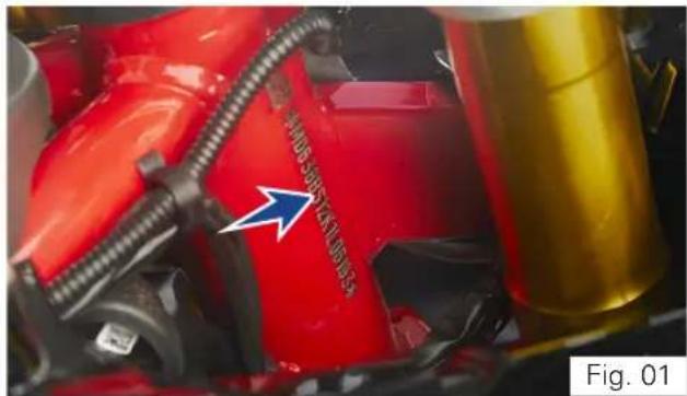
VEHICLE IDENTIFICATION NUMBER
All TVS motorcycles are provided with identification numbers for frame and engine. They are the only means of identifying your vehicle from others of the same model and type.
The frame identification number is engraved on therightofthesteeringheadtubeasshown (ref. Fig. 01).
The engine identification number is engraved on the right side of engine as shown (ref. Fig. 02).
natural_image
Close-up of a red automotive component with attached yellow cylinder and blue arrow indicator (no readable text or symbols)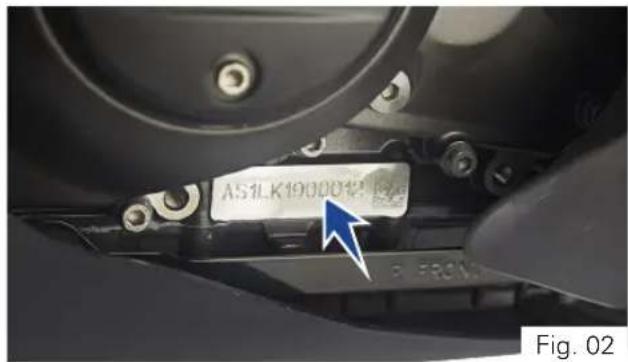
TVS Racing
Control Key
Your TVS Apache RR 310 comes with a pair of identical control keys. These keys are to operate ignition cum steering lock, fuel tank cap and seat lock.
A sticker ID (1) attached with keys has the identification number of keys. Please note down the identificationnumberbelowforfuturereference.
(ref. Fig. 03)
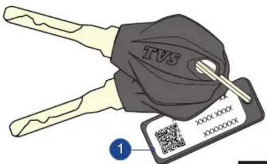
Fig. 03
Location of Parts - Vehicle RH Side View (Ref. Fig. 04)
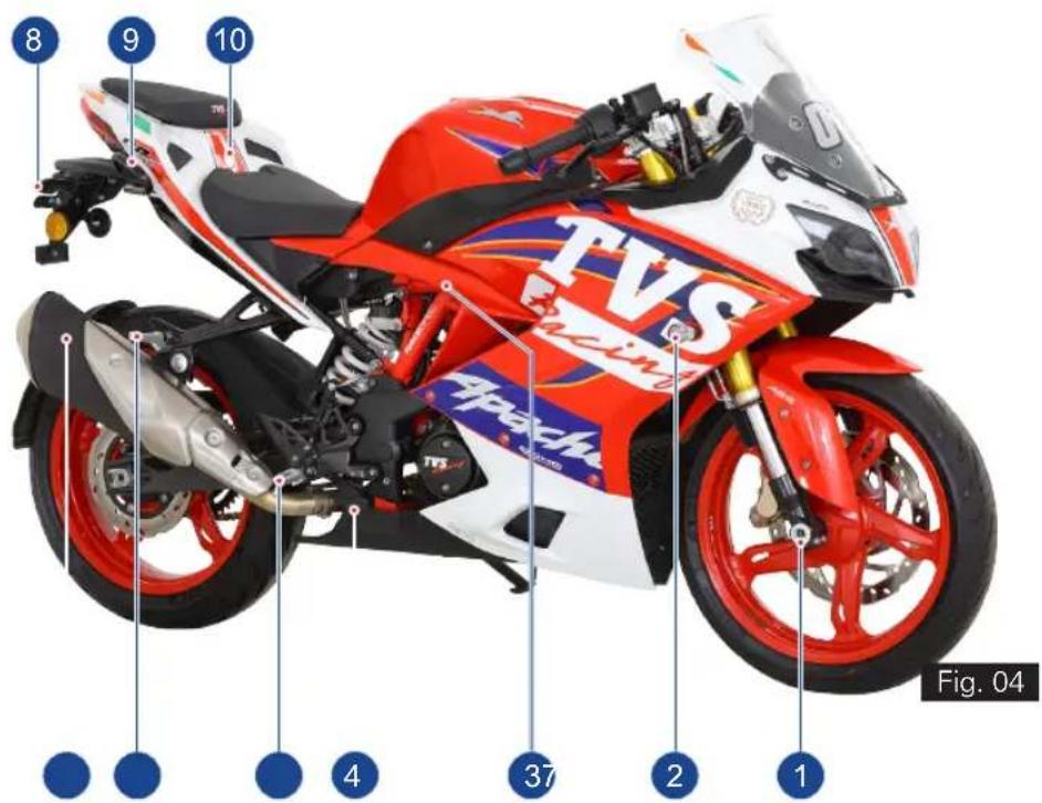
1) Front wheel axle
2) Turn signal lamp RH front
3) Reservoir, rearbrakefluid (ref. page 134)
4) Rear brake pedal (ref. page 28)
5) Rider foot rest RH
6) Pillion foot rest assembly RH
7) Muffler assembly
8) Turn signal lamp RH rear
9) Pillion handle
10) Seat lock (ref. page 99)
Location of Parts - Vehicle LH Side View (Ref. Fig. 05)
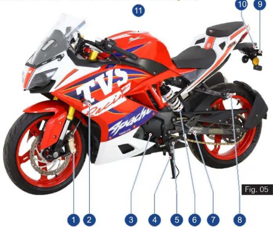
TVS Racing
- Caliper assembly front
- Turn signal lamp LH front
- Gauge oil level (dipstick) (ref. page 130)
- Side stand
- Gear shift pedal (ref. page 27)
- Rear shock absorber (ref. page 98)
- Rider foot rest LH
- Pillion foot rest assembly LH
- Turn signal lamp LH rear
- License plate lamp
- Fuel tank cap assembly (ref. page 95)

Warning
This section shows the position and function of the controls used to ride your motorcycle. Read this section carefully before riding the motorcycle.
Controls (ref. Fig. 06)
1) Instrument cluster (ref. page 32)
2) Ignition cum steering lock (ref. page 20)
3) Clutch lever (ref. page 21)
4) Switch assembly LH (ref. page 22)
5) Gear shift pedal (ref. page 27)
6) Rear brake pedal (ref. page 28)
7) Switch assembly RH (ref. page 29)
8) Throttle twist grip (ref. page 30)
9) Front brake lever (ref. page 31)
* Hidden items are marked with dotted lines
TVS Racing
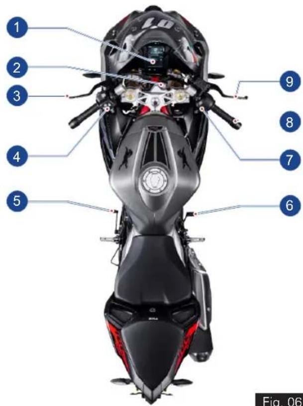
Fig. 06
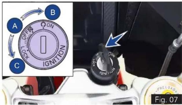
Ignition cum Steering Lock
Ignition cum steering lock is located in front of fuel tank and has three positions (ref. Fig. 07):
• OFF (A): Disables lights and engine operation.
- ON (B): Enables lights and engine operation (with engine cut off switch is in run mode ' ☐').
- LOCK (C): Steering is locked
- To lock the steering, turn the handle bar all the way towards 'left' or 'right', push the key in and turn it to LOCK position.
- Push and turn the key to OFF or ON position to unlock.

Note
Control key can't be taken out from the lock at position (B).
The head lamp, tail lamp and license plate lamp will glow automatically when the ignition is turned ON without operating any other switches.
The instrument cluster performs pre-check once the 'ignition lock' is turned ON. Wait till the completion of pre-check.

Caution
On level ground, always turn the handle bar towards left while locking the steering when the vehicle is propped with side stand. Else the vehicle may fall and may get damaged. Otherwise the angle of the ground determines the steering position ('left' or 'right').
Always lock the steering while parking for safety.
Ensure that, you do not keep the ignition 'ON' without starting the engine for a long time as battery might get drained because of AHO.
TVS Racing
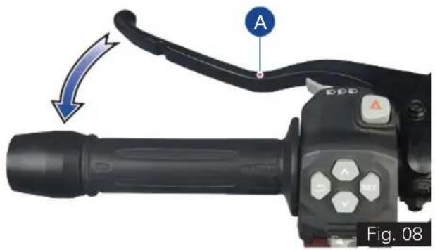
Clutch Lever (ref. Fig. 08)
Clutch lever (A) is located in the handle bar at LH side.
- Clutch lever is used to disengage clutch.
- When the clutch is pressed, drive from the engine to the gearbox and the rear wheel is disengaged.

Caution
Proper usage of clutch increases the life of engine component and prevent any damage to the transmission components of engine.
- Proper use of clutch lever is essential in all riding situations, especially while moving the vehicle from rest.

Note
Apply the clutch when starting the vehicle with gear engaged.
Increase in engine rpm during acceleration, without increase in road speed indicates the clutch slip. A slipping clutch causes high fuel consumption and engine overheating. Refer page 132 for clutch adjustment procedure.
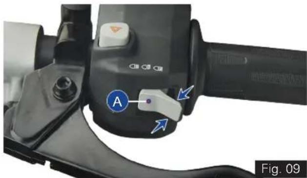
Switch Assembly LH
Switch assembly LH is located in the handle bar at LH side and has the following switches in it.
A) Switch beam control (ref. Fig. 09)
Head lamp glows automatically when the ignition turned ON. Depending on the selection of High/Low beam switch position, head lamp will operate in corresponding beam.
- Press the switch towards you ' to illuminate low beam
- Press the switch away from you ' to illuminate high beam.
- When the head lamp is illuminated in high beam, the high beam indicator 'glows along with it.

Warning
Use appropriate head lamp beam 'high / low' as per the traffic and road conditions for your safety and avoid inconvenience to other riders.
TVS Racing
natural_image
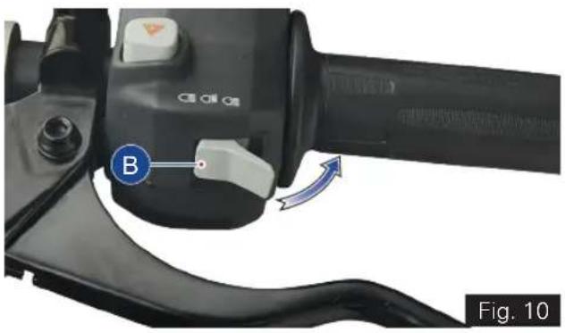
Close-up of a black mechanical device with labeled control buttons and a blue arrow indicator (no readable text or symbols)B) Pass-by switch (ref. Fig. 10)
- Press the switch intermittently to flash the head lamp.
- Flashing the head lamp high beam provides signal to the vehicles coming from opposite direction during overtakes.
- If the high beam is flashed, the high beam indicator ' - also flashes along with it in

the instrument cluster.
natural_image
Close-up of a black automotive brake lever handle with a blue circular indicator labeled 'B' and an arrow indicating rotation (no text or symbols on the lever itself)
Note
Pass by works only when the beam control switch is in low beam position.
C) Hazard switch (ref. Fig. 11)
- Press the button ' (C) to turn ON / OFF the hazard lamps.
- If the hazard indication is turned ON while the turn signal indicators are active, the turn signal indicators will be suspended temporarily.
- Turn signal indication will resume automatically once the hazard lamps are turned OFF (if they were active before hazard lamp ON).
- On activation of hazard lamps, both 'left' and 'right' turn signal indicators 'flashes.

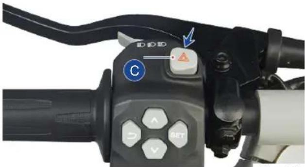
Fig. 11
Note
Hazard lamps can be switched ON/OFF only by means of hazard switch.
Hazard switch works only when the ignition is turned ON and the lamps continue to work even if the ignition is turned OFF during its working.
Avoid using hazard lamps while the engine is turned OFF for prolonging time to avoid battery drain.
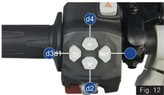
D) Control switches (ref. Fig. 12)
(d1) SET button (ref. Fig. 12)
- Press the button (d1) for selecting the menu display (Ride Mode, Trip Details, My Vehicle, Preferences).
- Press the SET button to enter / select.
- Press the SET button to accept an incoming call.
(d2)DOWN button (ref. Fig. 12)
- Press the button (d2) changing the current selection.
(d3) RETURN button (ref. Fig. 12)
- Press the button (d3) to exit the current menu and go back to the previous menu.
- Press the RETURN button to reject an incoming call.
(d4) UP button (ref. Fig. 12)
- Press the button (d4) directly from the home screen to toggle the ride modes.
- Press the UP button for changing the current selection.
TVS Racing

Warning
Display setting to be done only when the motorcycle is stationary. Never operate the control switches while riding the motorcycle for safety.
Usage of the control switches while riding, should be avoided for a safe ride.
E) Switch turn signal (ref. Fig. 13)
- Push the switch towards '←' to flash LH side turn signal lamps and towards '→' to flash RH side turn signal lamps.
- Push the switch 'IN' to cancel.
- When the 'left' or 'right' side turn signal lamps areactivated, respective turn signal indicator

cluster.
flashes along with it in the instrument
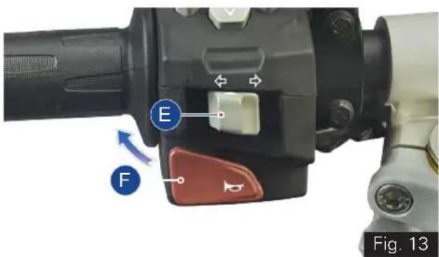
F) Switch horn (ref. Fig. 13)
- Press the switch ' to blow horn.
TVS Racing
Gear Shift Pedal (ref. Fig. 14)
This motorcycle is equipped with a 6 speed constant mesh transmission.
- To select the required gear or to bring the vehicle to neutral, a gear shift lever (A) is provided and it is located on the LH side of the vehicle.
- To engage the 1st gear and to down shift the gear press the pedal down.
- To engage 2nd, 3rd, 4th, 5th and 6th gear, lift the pedal upwards.
- Each time you move the pedal you will be engaging the next gear.
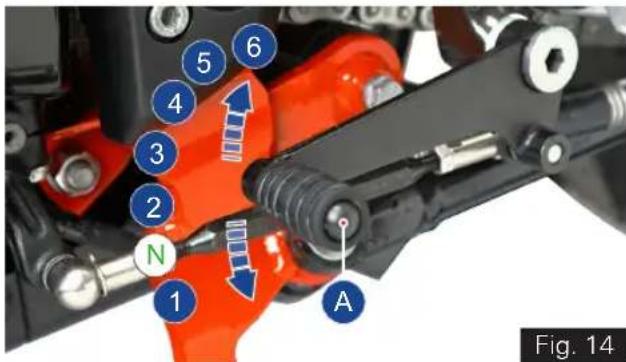
- Gear shift pedal returns to its position (centre position) automatically when released after shifting.
- Once the transmission is brought to neutral position, the neutral indicator 'N' illuminates.

Note
Apply the clutch when starting the vehicle with gear engaged.
Gear shift pedal position can be adjusted as per the convenience of the rider. Refer page 111 for adjusting procedure.

bar
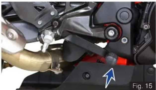
| Category | Value | |---|---| | Blue Bar | 27 | | White Bar | 27 |Rear Brake Pedal (ref. Fig. 15)
Rear brake lever (A) is located on the RH side of the vehicle.
- Push down the rear brake pedal with your right foot to operate the rear brake.
- The system is operated by hydraulic and just need to push the lever gently.
natural_image
Close-up of a motorcycle's mechanical components, including a brass pipe and black frame, with no visible text or symbols.Note
Front brake lever and rear brake pedal pulsates during the hard application of brake which is normal. This pulsation occurs because of ABS working.
Switch Assembly RH
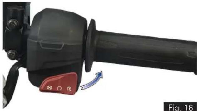
Switch assembly RH is located in the handle bar at RH side and has the following switches in it. Switch electric starter with Engine Kill switch (ref. Fig. 16)
This motorcycle is provided with integrated switch electric starter with engine kill switch.
- The engine kill switch is used to switch off ' ☒' the engine but to keep other DC system active.
- The ignition circuit is disabled, preventing the engine from being started. To restart the engine, return the switch to the 'O' position.
- To start the engine keep the switch in ' position, Ensure the transmission is in neutral or else press the clutch lever before engaging the starter switch.
Warning
Do not operate the kill switch when riding else you may fall due to rear wheel locking.
This switch is mainly intended for use in emergencies when you need to stop the engine quickly.
natural_image
Close-up of a black mechanical lever with red control knob and blue directional arrow (no text or symbols)Note
If the electric starter switch is pressed more than 3 seconds continuously, the starter motor gets disabled automatically and will not crank the engine. The motor cranks the engine only after 1 second or if the switch is released and repressed again.

Note
Please remember that the electric starter function will work only when the throttle opening is less than 30%.
Release the electric starter switch immediately after engine starts.
Starter switch will not work if it is pressed when the engine is running.
It is possible to start the vehicle with the side stand ON and gear box in neutral. When starting the bike with the gear engaged, apply the clutch (the side stand must be up in this case. If the side stand is in ON position, after vehicle start engine stops while changing the gear from neutral).
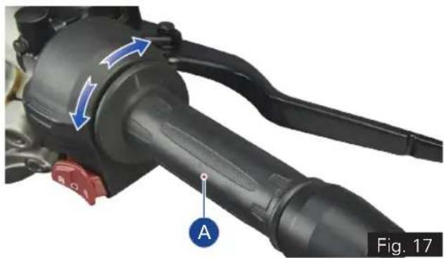
Throttle Twist Grip (ref. Fig. 17)
Throttle twist grip (A) is located in the handle bar at RH side.
• Twisting the grip opens the throttle.
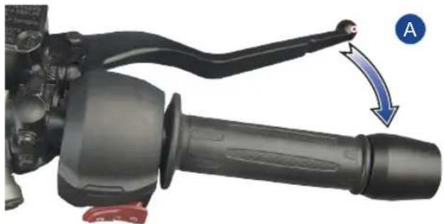
- Throttle grip spring back to the initial position (idling speed) when released. Front Brake Lever (ref. Fig. 18)
natural_image
Close-up of a mechanical lever assembly with blue arrows indicating motion direction (no text or symbols)Front Brake Lever (ref. Fig. 18)
Front brake lever (A) is located in the handle bar at RH side.
- Pull the lever towards the throttle twist grip to operate the front brake.
- The system is operated by hydraulic and just need to press the lever gently.
natural_image
Close-up of a mechanical lever handle and grip mechanism with a blue arrow indicating motion direction (no text or symbols)Fig. 18
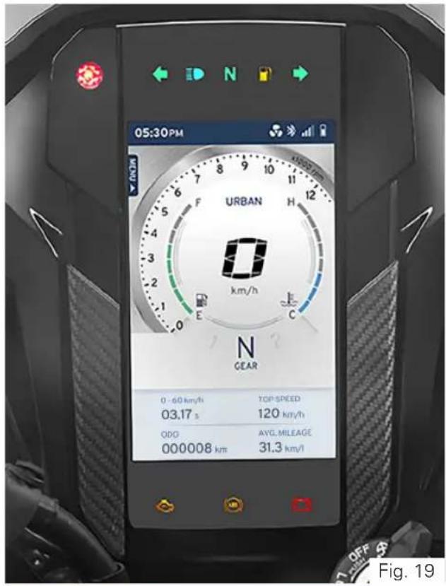
CONNECTED TFT INSTRUMENT CLUSTER KEY FEATURES (ref. Fig. 19)
- Your motorcycle is fitted with a 5" TFT instrument cluster.
- It has an advanced UI /UX design for TFT screen with cognitive ergonomics.
- The cluster has 4 different themes for 4 different rides in Day & Night modes which give you a rich user experience.
- The TFT cluster in combination with infotainment switch enables you on-the-go mode selection.
- Gear shift assist display helps you to drive your motorcycle for the best performance or fuel economy depending on the ride mode you have selected.
- In-built photo-sensor helps to automatically adjust the brightness and change the day and night mode of the screen if it is in AUTO.
- User alerts are made easy and effective with warnings and messages on the screen.
- Layout, font size, colors and themes enable quick and easy data access.
TVS Racing

Warning
Risk of accident through the use of integrated information systems and communication devices during the journey.
Operate these systems or devices only if the traffic situation allows. If necessary, stop and operate the system or devices at a standstill.
TFT Instrument Cluster
Instrument cluster will be activated once the 'ignition lock' is turned ON.
All segments and tell-tale indicators glow for 2 seconds on activation of instrument cluster for checking and ensuring the proper working of segments and indicators.
Following are the features of instrument cluster:
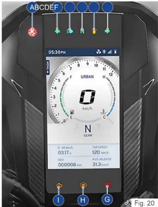
1) Warning and indicator lights (ref. Fig. 20)
A) Gear shift / Rev indicator / Photo sensor
B) Turn signal indicator LH
C) High beam indicator
D) Neutral indicator
E) Low fuel warning indicator
F) Turn signal indicator RH
G) Low battery indicator
H) ABS indicator
I) EMS malfunction indicator
Warning and indicator lights (ref. Fig. 20)
| Symbol Lights Meaning | ||
 | A. Gear shift indicator | In Urban & Rain mode, the shifting indicator blinks at lower speed of the vehicle when the throttle is below 25% and when the throttle is at 26% to 55%, it blinks at little higher speed of the vehicle to get the better fuel efficiency.In Sport & Track mode, the indicator glows when the engine reaches maximum revolutions per minute (RPM).Adjusts the TFT brightness and tell tale indicators brightness automatically as per day and night conditions. |
| Rev indicator | ||
| Photo sensor | ||
 | B. Turn signal indicator LH Flashes when the left side turn signal indication is activated | |
 | C. High beam indicator Glows when the head lamp high beam is activated | |
 | D. Neutral indicator Glows when the vehicle is in neutral condition | |
 | E. Low fuel warning indicator | Glows when the fuel level in the tank reaches to minimum safe level or any malfunction in the fuel level sensor* |
* Contact TVS Motor Company Limited Authorised Main Dealer
| Symbol Lights Meaning | |
 | F. Turn signal indicator RH Flashes when the right side turn signal indication is activated |
 | G. Low battery indicator Glows when the battery voltage is low* |
 | H. ABS indicator Flashes when the ABS self-diagnostic not completed / not yet initiated - Ride the vehicle few kms.Glows continuously when the ABS has an error or malfunction*Goes OFF after few kms run - ABS is active and ready to use |
 | I. EMS Malfunction indicator Glows when any problem is detected in the engine management system causing vehicle to exceed on-board diagnostic emission threshold.*Blinks continuously when engine mis-fire is detected once the engine is started (mis-firing detection is applicable only for OBD II vehicle)*. |

Note
The vehicle automatically goes to reduced performance mode if the engine temperature is very high.
* Contact TVS Motor Company Limited Authorised Main Dealer
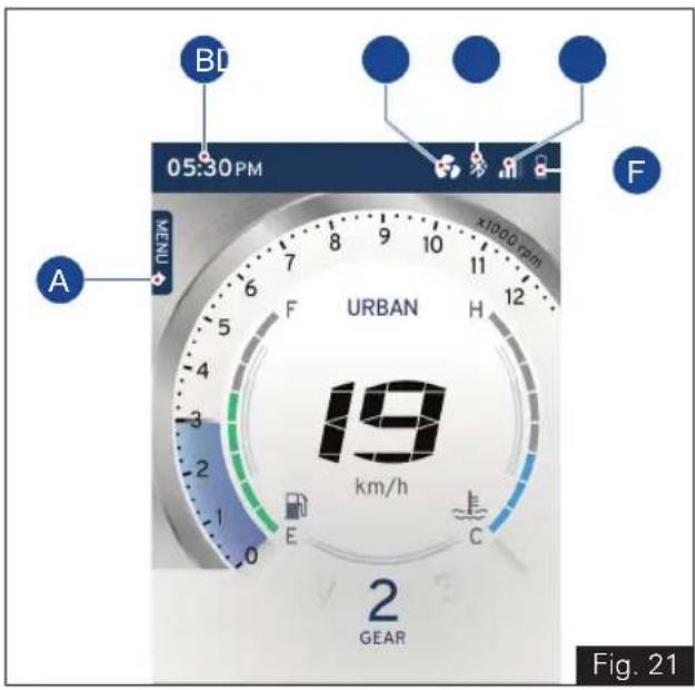
2) TFT Multifunction display (ref. Fig. 21)
A) Menu indication
B) Clock
C) Cooling fan status
D) Bluetooth connectivity indication
E) Mobile signal strength
F) Mobile battery status
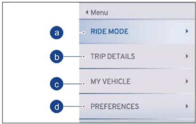
A) Menu indication
TVS Apache RR310's connected instrument TFT cluster offers you different function of display to choose. The sequence of the functions, their selection and their working are explained in the following pages.
a). Ride Mode
b). Trip Details
c). My Vehicle
d). Preference
- Displays the menu selected by the user.
To set the menu:
- Keep the vehicle stationary and switch ON the ignition. After the self-check press the 'SET' button, (ref. Fig. 08 for possible menu display)

Note
For your safety, it is not allowed to navigate through the menu which is not of high importance while riding the bike.
Once your vehicle goes above a speed of 5 kmph, the sub-functions (MY VEHICLE and PREFERENCES) get locked.
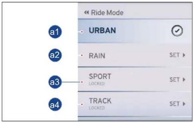
a) Ride Mode
In 'RIDE MODE' you have four different types of modes in display to choose the desired ride mode using UP and DOWN button. Press the 'SET' button to select the chosen ride mode.
The modes are explained in the following pages in the below sequence.
a1. Urban Mode
a2. Rain Mode
a3. Sport Mode
a4. Track Mode

Note
The above mode changes are possible only when the throttle is fully closed.
TVS Racing
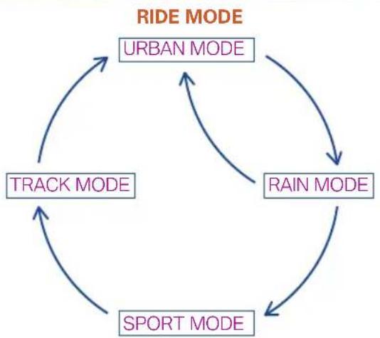
flowchart
graph TD
    A["URBAN MODE"] --> B["RAIN MODE"]
    B --> C["SPORT MODE"]
    C --> D["TRACK MODE"]
    D --> A
Note
On ignition 'OFF' and 'ON' the previously displayed mode will be retained in display of the connected TFT instrument cluster.
In order to improve performance, consistency and durability of your motorcycle, the maximum vehicle speed will be reduced during the initial running-in period (1000 km).
You can access SPORT & TRACK mode only after completing the running-in period, i.e., first 1000 km.
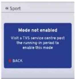
Once you cover the running-in period, Contact TVS Motor Company Authorised Main Dealer for enabling the locked modes.
Caution
In case any fault is detected with respect to the ride mode change in the EMS or ABS system, then your motorcycle will operate only in the URBAN mode.
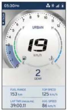
a1. Urban Mode
Urban mode has been associated with 2 different themes for day and night modes.
Day Mode Night Mode
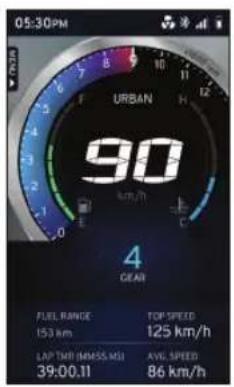

Note
Please note that the top speed for Urban mode is limited to 125 kmph and also ABS performance is tuned for Urban mode and will be different for other modes.
If you desire to ride your motorcycle at a speed higher than the above-mentioned value, ensure to change the ride mode to Sport or Track mode. For further details, visit TVS Motor Company Authorised Main Dealer.
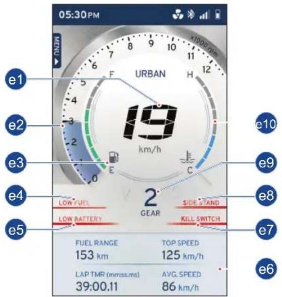
a1.Urban Mode
In Urban mode, the following features will be displayed on the instrument TFT cluster :
e1. Speedometer
e2. Engine rpm indicator
e3. Fuel level indicator
e4. Low fuel warning indicator
e5. Low battery warning indicator
e6. Widgets indicator
e7. Kill switch indicator
e8. Side Stand warning indicator
e9. Gear position indicator
e10. Coolant temperature indicator
e1. Speedometer
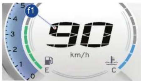
• Displays the road speed in km/h (f1) (in India).
e2. Dynamic engine rpm indicator
- Digital band (f2) indicates the engine rpm in multiples of 250 rpm.
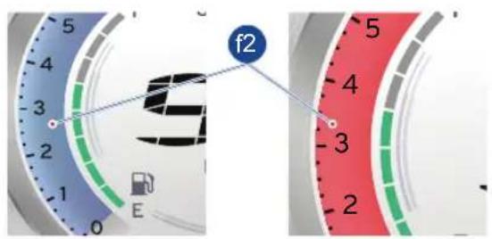
- Digital bands are indicated in blue and red band based on the engine coolant temperature. Refer bellow table for details.
| Engine Coolant temperature | Blue band RPM range | Red band RPM range |
| -25°C to 20°C 0 | - 5000 rpm 5000 | - 12000 rpm |
| 20°C to 60°C 0 | - 7000 rpm 7000 | - 12000 rpm |
| 60°C to 120°C 0 | - 10500 rpm 10500 | - 12000 rpm |
| Above 120°C Engine will cut-off. | ||
TVS Racing
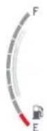
e3. Fuel level indicator
- Digital bars (f3) indicates the approximate quantity of fuel available in the tank.
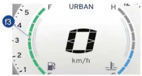
- There are eight bars to indicate the quantity fuel. - All the eight bars will be displayed when the fuellevelinthetankreachesapproximately 9 liters.
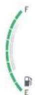
- When the fuel level reduces to 5 liters (approx.) the indicator displays only five bars.

- If the fuel level is less than 2.2 liters, the low fuel indicator ' ’ starts glowing.
- If the fuel level reaches to minimum safe level ie. lesser than 2 liter approximately, fuel level indicator displays a single bar.
- Fill fuel (ref. page 95) immediately.

Note
Please ensure that the fuel bar indication in cluster is greater than 1 bar always. It is unsafe to ride with 1 bar or less.
In case of any error in input system, all the bars of fuel level indicator flashes and low fuel warning indicator turns ON. Contact nearest TVS Motor Company Authorised Main Dealer incase any of these problems are noticed.

Warning
If the vehicle runs with very less fuel it will result in improper engine operation or shutdown due to lack of fuel which may result in accident.

Caution
Do not run the fuel tank dry to avoid failure of fuel pump and other consequential damages if any.
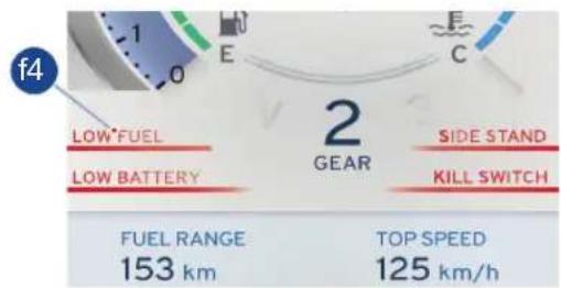
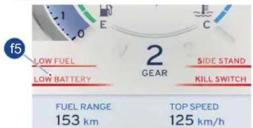
e4. Low fuel warning indicator
- Low fuel warning indicator (f4) is a safety indicator to caution you to fill the petrol as soon as possible. Minimum 2.2 liters of petrol will be available in the tank when this indicator comes glows.

Caution
When the low fuel warning indicator glows fill fuel immediately to avoid engine OFF/Damage to fuel pump which leads to replacement of pump without warranty.
TVS Racing
e5. Low battery warning indicator
- Low battery warning indicator (f5) appear when the battery charge is too low. Get the battery checked at TVS Motor Company Authorised Main Dealer.
- While riding if there is any fault in the charging system, then a warning message will be displayed on the TFT screen as "VISIT TVS SERVICE CENTER" and along with this the low battery indicator (ref. page 34).
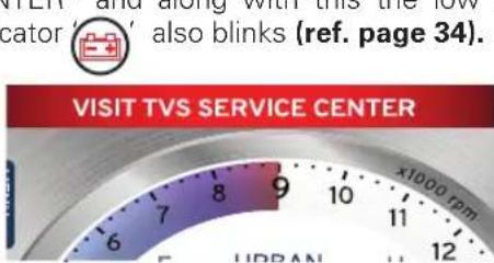
- If still the fault in the charging system continues then the Gear shift indicator (ref. page 34) also blinks along with the low battery indicator.
- When this warning message occurs take the vehicle immediately to TVS Motor Company Authorised Main Dealer.
Caution
If this warning message occurs the vehicle can be ridden for approx. 25 kms or 40 minutes only (which depends on the state or health of the battery).
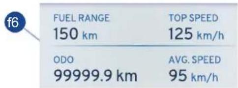
e6. Widgets indicator
- Widgets (f6) indicates the (viz. ODO, IMI, Avg. Speed, Avg. Mileage etc.) can be used to display live feeds in the home screen of your TFT instrument cluster.

Note
To change the widgets in the home screen of your TFT instrument cluster (ref.page 72).
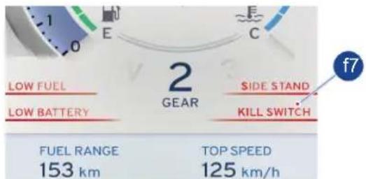
e7. Kill switch indicator
- When the ignition is ON but engine is OFF condition the kill switch indicator (f7) will display in connected TFT instrument cluster.
- It is a safety feature that can be used to cut power to the engine in the event of an emergency.
e8. Side stand warning indicator
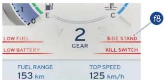
- If the side stand is ON, the text message (f8) will be displayed in connected TFT instrument cluster.

Note
The vehicle will start in side stand in neutral gear but not in other gears. The vehicle will also 'switch off' if the side stand is ON and gear is changed from neutral to gear.
In case of any errors in side stand switch - side stand indication will be always ON in the instrument cluster immaterial of side stand status.
In the event of any unfortunate accident, if the side stand / side stand switch has been damaged, the signal can be bypassed by disconnecting the side stand switch coupler.
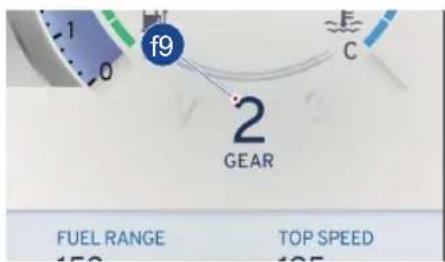
e9. Gear position indicator
- Gear position indicator (f9) indicates vehicle's present gear position and neutral condition. Gear position indication displays “—” if there is any problem in the system. Take the vehicle to TVS Motor Company Authorised Main Dealer.
TVS Racing
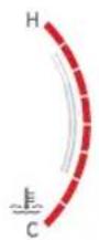
e10. Coolant temperature indicator
- Digital bars (f10) indicates the engine coolant temperature.
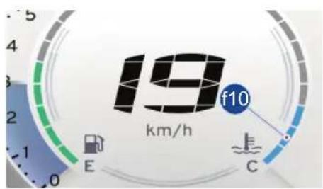
- The coolant temperature indicator displays more than six bars if there is any problem in the cooling system.
- In case of any error in input system, all the bars coolant temp indicator flashes. - Take the vehicle to TVS Motor Company Authorised Main Dealer for further diagnosis.
Note
The vehicle automatically goes to reduced performance mode if the engine temperature is very high.
a2. Rain Mode
Rain mode has been associated with 2 different themes for day and night modes.
Day Mode Night Mode
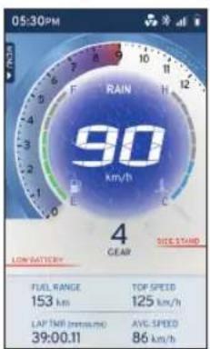
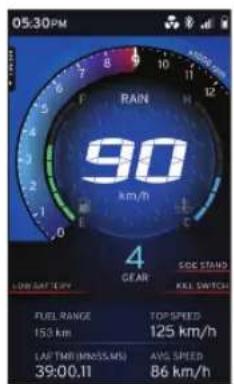

Note
All the features are similar like Urban mode. Refer urban mode for the detailed explanation.
Although, vehicle performance will be changed due to the change in ride mode. In rain mode top speed of the vehicle is limited to 125 kmph.
If you desire to ride your motorcycle at a speed higher than the above-mentioned value, ensure to change the ride mode to Sport or Track mode. further details visit TVS Motor Company Authorised Main Dealer.
a3. Sport Mode
Sport mode has been associated with 2 different themes for day and night modes.
Day Mode Night Mode
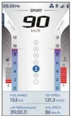
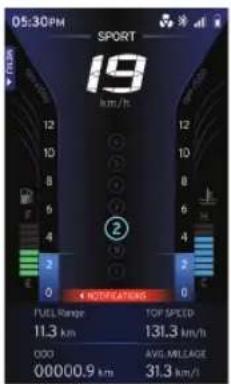

Note
All the features are similar like Urban mode with some notable changes in the UI (graphics). Refer urban mode for the detailed explanation. Although, vehicle performance will be changed due to the change in ride mode.
In sport mode top speed of the vehicle is limited to 160 kmph.
You can access SPORT & TRACK mode only after completing the running-in period, i.e., first 1000 km. Once you cover the running-in period, Contact TVS Motor Company Authorised Main Dealer to enable the locked modes.
a4. Track Mode
Track mode has been associated with 2 different themes for day and night modes.
Day Mode Night Mode
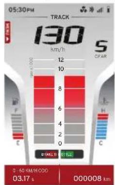
bar
130 km/h S CFAR 0-60 KM/H/00:00 03.17 s 000008 km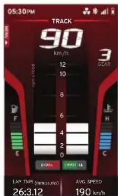
Note
All the features are similar like Urban mode with some notable changes in the UI (graphics). Refer urban mode for the detailed explanation. Although, vehicle performance will be changed due to the change in ride mode.
In track mode top speed of the vehicle is limited to 160 kmph. There is a reduction in the number of widgets (2 Nos.) when compared to the other ride modes.
You can access SPORT & TRACK mode only after completing the running-in period, i.e., first 1000 km. Once you cover the running-in period, Contact TVS Motor Company Authorised Main Dealer for enable the locked modes.
b) Trip Details
- Displays the menu selected by the user.
To set the menu:
- Keep the vehicle stationary and switch ON the ignition. After the self-check navigate to 'TRIP DETAILS' in menu and press the 'SET' button to select the following function.
| Menu | |
| RIDE MODE | |
| TRIP DETAILS | |
| MY VEHICLE | |
| PREFERENCES | |
- Totally 4 trip meters namely Trip A, Trip B, Trip C and Day trip meter are available.
| « Trip Details | |
| TRIP A | SET ▶ |
| TRIP B | SET ▶ |
| TRIP C | SET ▶ |
| DAY TRIP METER | SET ▶ |
TVS Racing
- Trip details such as distance covered, time traveled, average speed, top speed, fuel consumed and average mileage are recorded by the trip meter for individual journeys.
| < trip A | |
| TOTAL DISTANCE COVERED9999.9 kmLIMIT REACHED | TOTAL TIME TRAVELLED12:18:42hh:mm:ss |
| AVG. SPEED95 km/h | TOP SPEED122 km/h |
| FUEL CONSUMED999.9 litres | AVG. MILEAGE33.2 km/l |
- You can reset it whenever you wish to record the data for new journey.
- Press the DOWN button; RESET option gets selected. Then press the 'SET' button to reset the trip details.
- Press the 'Return' button to menu display (ref. page 25).
- Day trip meter recarded the trip details such as distance covered, time traveled, average speed, top speed, fuel consumed and average mileage on that particular day.
| DAY TRIP METER | |
| TOTAL DISTANCE COVERED159.9 km | TOTAL TIME TRAVELLED06:18:42hh:mm:ss |
| AVG.SPEED99.7km/h | TOP SPEED122km/h |
| FUEL CONSUMED4.9 litres | AVG.MILEAGE33.2km/l |
- The values will get reset in case of change in date and long idle i.e more than 4 hours.
Note
Add trip meter as a widget to see the trip ODO value (ref. page 72).
c) My Vehicle
- Displays the menu selected by the user.
To set the menu:
- Keep the vehicle stationary and switch ON the ignition. After the self-check get into menu and select the 'MY VEHICLE' and press the 'SET' button to select the following function.
| Menu | |
| RIDE MODE | |
| TRIP DETAILS | |
| MY VEHICLE | |
| PREFERENCES | |
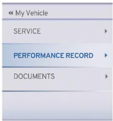
- There are 3 option available in the 'MY VEHICLE'.
◆ SERVICE
◆ PERFORMANCE RECORD
DOCUMENTS
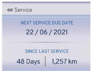
SERVICE
By press the 'SET' button on select the SERVICE option.
| My Vehicle | |
| SERVICE | |
| PERFORMANCE RECORD | |
| DOCUMENTS | |
- Upcoming service date for your vehicle will be disclosed in the service menu.
- In addition to that, days and kilometers from last service will be also displayed.
- Pressthe'Return'buttontomenudisplay (ref. page 25).
- Press the down button to select the PERFORMANCE RECORD and press the 'SET' button to select the following function.

Note
'SERVICE DUE' notification will pop-up on your cluster if your motorcycle is either 300 km ahead of the recorded service kilometers or 7 days prior to the service date.
In case you fail to service your motorcycle within the prescribed date and kilometers, 'SERVICE OVERDUE' message will be displayed on the cluster.
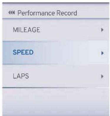
- There are 3 option available in the 'PERFORMANCE RECORD'.
MILEAGE
◆ SPEED
LAPS
MILEAGE
- By pressing the 'SET' button on select the MILEAGE option.
| Performance Record | |
| MILEAGE | |
| SPEED | |
| LAPS | |
- Average mileage of your vehicle will be calculated and displayed for your knowledge.
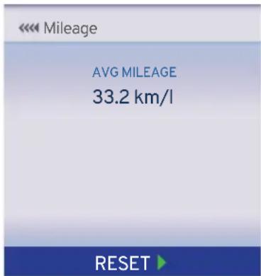
- Since this data is resettable, you can reset it if you wish to. Press the DOWN button; RESET option gets selected. Then press the 'SET' button to reset the mileage details.
TVS Racing
◆ SPEED
- Press the down button to select the SPEED and press the 'SET' button to select the following function.
- In this menu, average speed, time taken for 0-60 km/h and top speed of your motorcycle are disclosed.
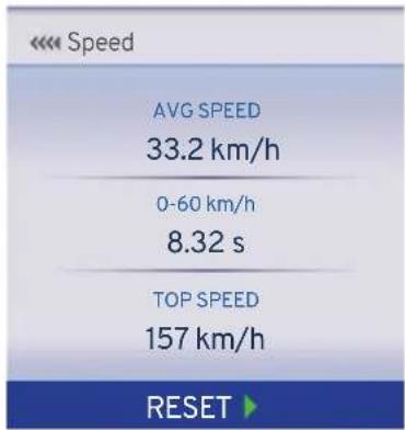
- Since this data is resettable, you can reset it if you wish to. Press the DOWN button; RESET option gets selected. Then press the 'SET' button to reset the speed details.
LAPS
- Press the down button to select the LAPS and press the 'SET' button to select the following function.
| Performance Record | |
| MILEAGE | |
| SPEED | |
| LAPS | |
- The cluster of your motorcycle can store a maximum of 10 laps along with the date and time when the lap was triggered.
- 'Best lap' duration is shown based on the 10 lap durations displayed.
| < Laps (mm:ss.ms) |
| BEST LAP29:12.32 |
| Laps | BEST LAP29:12.32 |
| Showing 1-4 of 10 | |
| 1) 30:34.22 | 22/06/2018 - 06:33PM |
| 2) 31:34.22 | 22/06/2018 - 06:33PM |
| 3) 29:34.22 | 22/06/2018 - 06:33PM |
| 4) 29:12.32 | 22/06/ 2018 - 06:33PM |
- Since this data is resettable, you can reset it if you wish to. Press the DOWN button; RESET option gets selected. Then press the 'SET' button to reset the Laps details.
DOCUMENTS
Documents such as Driving license, RC book, Aadhar card etc. can be uploaded from TVS Connect app to TFT Instrument Cluster using both Android and iOS mobile phones ref. page 90.
- Press the down button to select the DOCUMENTS and press the 'SET' button to select the following function.
| « My Vehicle | |
| SERVICE | ▶ |
| PERFORMANCE RECORD | ▶ |
| DOCUMENTS | ▶ |
- In this menu, list of documents uploaded from your smart phone through TVS connect app can be seen
- Press the 'SET' button to open the desired documents.
| << DOCUMENTS | |
| DOCUMENTS 1 | |
| DOCUMENTS 2 | |
| DOCUMENTS 3 | |
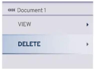
- Press the 'SET' button after selecting the VIEW option, to either view the status of image transferred or image itself after it is transferred.
| << Document 1 | |
| VIEW | ▶ |
| DELETE | ▶ |
- Press the down button to select the DELETE and press the 'SET' button to delete the document.

TVS Racing
Note
Total of 3 documents can be stored in the TFT Instrument cluster.
Document transfer will work only when VIN number in the TVS Connect App matches vehicle VIN.
Document transfer cannot be initiated once app is connected for ride.
Ride can be connected when image transfer is in progress but 'Start Tour' functionality will not work when document transfer is in progress.
Rate of document transfer may vary, based on type of mobile and software version.
When ride is connected and document transfer is also ongoing, rate of document transfer may be reduced.
In case if document is transferred partially and deleted from TVS Connect App, please ensure that document is also deleted from cluster before syncing the new document in the same slot in cluster.
In case of IG on/off during document transfer, document transfer will not resume until user clicks on resume button in TVS Connect App.
TVS Racing
d) PREFERENCES
• Displays the menu selected by the user.
To set the menu:
- Keep the vehicle stationary and switch ON the ignition. After the self-check press the down button to select the 'PREFERENCES' and press the 'SET' button to select the following function.
| Menu | |
| RIDE MODE | |
| TRIP DETAILS | |
| MY VEHICLE | |
| PREFERENCES | |
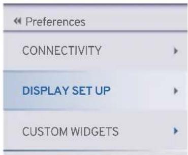
• There are 4 option available in the 'PREFERENCES'.
- CONNECTIVITY
◆ DISPLAY SET UP
CUSTOM WIDGETS
◆ SPEED ALERT
| Preferences | |
| CONNECTIVITY | |
| DISPLAY SET UP | |
| CUSTOM WIDGETS | |
| SPEED ALERT | |
- CONNECTIVITY
- By press the 'SET' button on select the CONNECTIVITY option.
• There are 2 option available in the CONNECTIVITY.
PAIRED DEVICES
◆ DISPLAY CALLS
TVS Racing
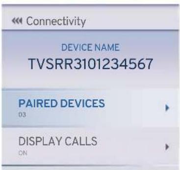
◆ Paired Devices
- By press the 'SET' button on select the PAIRED DEVICES option.
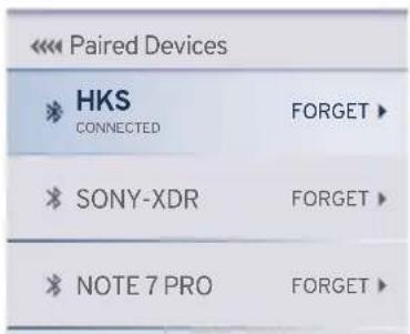
- It shows number of devices paired in the TFT instrument cluster.
- To remove the paired device from the TFT instrument cluster press the 'SET' button on the selected device name.
- Adding new device to vehicle (ref.page no 84)
◆ DISPLAY CALLS
- Press the down button to select the DISPLAY CALLS and press the 'SET' button to select the following function.
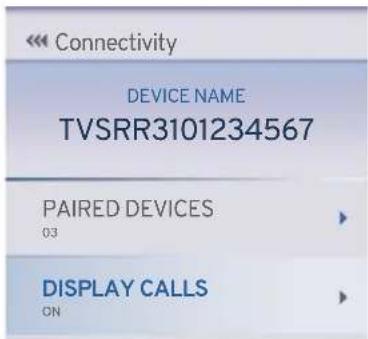
- Press the 'SET' button to ON or OFF to avoid the display calls visible in connected TFT instrument cluster.
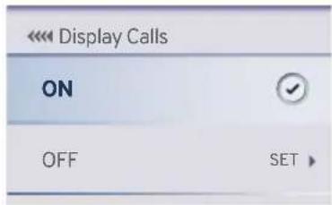
- If display calls setting is ON condition.
- The connected TFT instrument cluster will display the incoming calls alerts from the smart phone via Bluetooth. Ex. CALL FROM 'Arun Ramakrishnan', will be displayed if the contact is stored in the smart phone's otherwise number will be displayed.

- Press the 'SET' button to accept the incoming call. Press the 'RETURN' button to reject the incoming call (ref. page 25).
Note
Telephony features are disabled in TRACK mode for a safe ride.
Caution
To avoid risk of accident, and breach of Motor Vehicle Act & Rules, it is highly recommended not to respond to mobile call by operating the handle bar switches for accepting or rejecting the calls when the vehicle is in motion.
TVS Racing
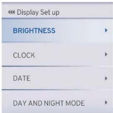
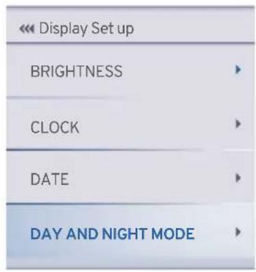
◆ DISPLAY SETUP
- Press the down button to select the DISPLAY SETUP and press the 'SET' button to select the following function.
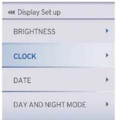
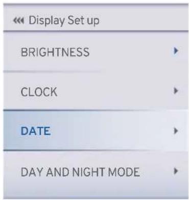
- There are 4 option available in the 'DISPLAY SETUP'.
BRIGHTNESS
- By press the 'SET' button on select the BRIGHTNESS option.
TVS Racing
- BRIGHTNESS
- By press the 'SET' button on select the BRIGHTNESS option.
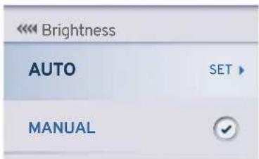
- By press the 'SET' button on select the AUTO option.
- Adjusts the TFT brightness and tell tale indicators brightness automatically as per day and night conditions (ref. page 34).
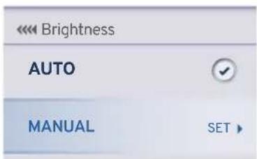
- Press the down button to select the MANUAL and press the 'SET' button to select the following function.
- Press the UP button to increase the brightness and the DOWN button to reduce the brightness of the cluster.
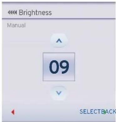
- Press the SET button after choosing the desired brightness level.
Note
The brightness ranges between 1 to 10 and can be set as per your preference.
♦ CLOCK
- Press the down button to select the CLOCK and press the 'SET' button to select the following function.
- The time displayed on the cluster will get auto-synced once the mobile is connected (ref. page 37).
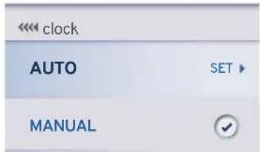
Note
The clock time gets sync automatically on paring your Android and iOS smart phone with the connected TFT instrument cluster provided if auto sync clock setting is enabled in app.
- Press the down button to select the MANUAL and press the 'SET' button to select the following function.
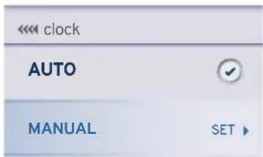
- In manual select the desired time format (12-hour or 24-hour) and press the 'SET' button.

- For 12-hour press the UP button to increase the hour value and press the DOWN button to decrease the hour value.
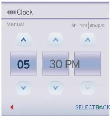
- Press the 'SET' button after setting the hour value and for proceeding to set the minute value.
- Similarly, for the minute setting, press the UP button to increase the minute value and the DOWN button to decrease the minute value.
- Press the 'SET' button after having set the correct minute value.
TVS Racing
- Toggle between AM and PM using the UP and DOWN buttons and then press the 'SET' button.
- For 24 hours press the down button to select the 24 HOUR and press the 'SET' button to select the following function.

- Press the UP button to increase the hour value and press the DOWN button to decrease the hour value.
- Press the 'SET' button after setting the hour value and for proceeding to set the minute value.
- Similarly, for the minute setting, press the UP button to increase the minute value and the DOWN button to decrease the minute value.
- Then press the 'SET' button to save the set time in the chosen format.
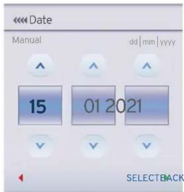
◆ DATE
- Press the down button to select the DATEand press the 'SET' button to select the following function.
- The date displayed on the cluster will get auto-syncedoncethemobileisconnected (ref. page 36).
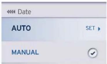
Note
The date gets sync automatically on paring your Android and iOS smart phone with the connected TFT instrument cluster provided if auto sync date setting is enabled in app.
- Press the down button to select the MANUAL and press the 'SET' button to select the following function.
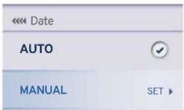
TVS Racing
- Press the UP button to increase the date and the DOWN button to decrease the date.
- Similarly, using the UP and DOWN buttons, select the current month and year.
- Then press the 'SET' button to save the date.
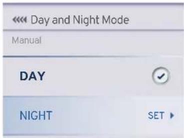
◆ DAY AND NIGHT MODE
- Press the down button to select the DAY AND NIGHT MODE and press the 'SET' button to select the following function.
- In the connected TFT instrument cluster, with the help of photo sensor, the Day & Night mode themes will be changed automatically.
TVS Racing
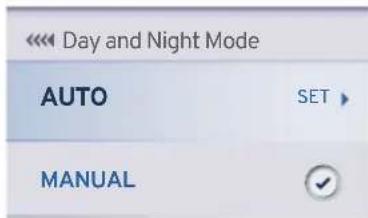
- Press the down button to select the MANUAL and press the 'SET' button to select the following function.
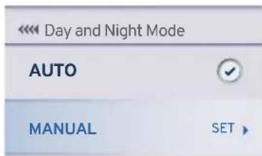
- In case you need to set the theme to Night mode, press the down button to select Night and then press 'SET' button to save the setting.
TVS Racing
CUSTOM WIDGETS
- Press the down button to select the CUSTOM WIDGETS and press the 'SET' button to select the following function.
| Preferences | |
| CONNECTIVITY | |
| DISPLAY SET UP | |
| CUSTOM WIDGETS | |
- Widgets (viz. ODO, IMI, Avg. Speed, Avg. Mileage etc.) can be used to display live feeds in the home screen of your connected TFT instrument cluster.
-
From a list of below-mentioned12 specified widgets, you can select any 4 for displaying on the widget screen:
-
Odometer
- Top Speed
- Avg. Mileage
-
Coolant Temp
-
0-60 km/h
• IMI - Lap TMR (lap timer)
- Range
- Avg. Speed
- Trip A Meter
- Trip B Meter
- Trip C Meter
- Press the up and down button to select the CUSTOM WIDGETS and press the 'SET' button to select.
| << Custom Widgets | |
| WIDGET-1TOP SPEED | ▶ |
| WIDGET-2AVG. SPEED | ▶ |
| WIDGET-3ODOMETER | ▶ |
| WIDGET-4IMI | ▶ |

Note
For URBAN, RAIN and SPORT modes, you can select any 4 of the 12 widgets for being disclosed on the home screen.
On TRACK mode, you can select any 2 of the 12 widgets for being disclosed on the home screen.
- Odometer
ODO 99999.9 km
◆ (Odo meter) displays the total distance covered by the vehicle.
- The reading is saved permanently and cannot be reset under any circumstances.
- If the travelled distance exceeds 999999 km, the value '99999.9' will be displayed permanently.
- Top Speed
TOP SPEED 131.3 km/h
- Displays the top speed achieved by any user so far.
- If the vehicle's current speed is greater than the recorded speed, the new value will get updated automatically.
- User can reset and record a new speed data if required.
- To reset the value (ref. page 58).
TVS Racing
- Avg. Mileage
AVG. MILEAGE
31.3 km/l
◆ Indicates the average mileage (fuel economy) of the vehicle.
- User can reset the value.
- This value gets updated only after the vehicle speed increases more 10 km/h for the first time after ignition ON and continue to update till the engine switch OFF.
- To reset the value (ref. page 58).
- Coolant Temp
COOLANT TEMP
32.5°C
◆ Coolant temperature indicator indicates the engine temperature in degree Celsius.
- Take the vehicle to the TVS Motor Company Authorised Main Dealer for further diagnosis if this indicator starts flashing.
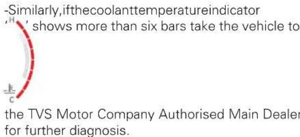
Caution
In case of coolant temperature sensor fault or cooling fan fault or throttle position sensor fault, the vehicle will go to reduced performance mode (limp-home) in order to safe guard the bike from any damage and also to protect the rider.
- 0-60 km/h
0 - 60 km/h
3.82 s
This function lets you to measure the time to reach 0 to 60 km/h speed from rest and to view the best time taken so far.
- If the current time is lesser than the stored value, the new value will get updated automatically.
- Toggle the display navigate to 'performance record' in menu to reset the value (ref. page 58).
• IMI
IMI
31.3 km/l
◆ Indicates the instantaneous mileage (fuel economy) of the vehicle at that particular driving condition.
- The value will not be shown if the vehicle speed is less than 10 km/h.
- Lap Timer
LAP TMR (mm:ss.ms)
39:00.11
- Press the pass-by switch for about 2 seconds to trigger lap counter. The lap timer widget will show the current lap time.
- To end the current lap and start new lap, press the pass-by switch again.
- To stop the lap counter, long press the pass-by switch for more than 2.5 seconds. The lap timer widget then shows the last lap time.
- This widget displays the current lap time and once the current lap is stopped then the last recorded time will be displayed.
• Each lap must have a minimum duration of 10 seconds.
- The connected TFT instrument cluster can store a maximum of 10 laps along with the date and time when the lap was triggered.
- 'Best lap' duration is shown based on the 10 lap durations stored and displayed in the menu under PERFORMANCE RECORD.
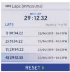
- To reset the value (ref. page 59).
TVS Racing
Note
After 10th Lap if the 11th lap is triggered then the values will be updated inside the LAP Menu on first in first out basis. This means 10th value in the LAP menu will show the latest data always.
If a particular lap time reaches 99 minutes, the current lap gets reset to 0.
The 'lap' function is disabled automatically if the 'ignition lock' or 'switch engine cut off' is turned OFF while it is active and the current lap time will not get stored even though the lap timer had been active before the turning OFF the 'lock / switch'.
If the lap timer function is switched ON when only fewer laps have been completed earlier (eg. 4 laps completed), it starts from the next lap only (5th lap) and not from the first.
In the lap timer, complete stored laps can be reset.
- Range
FUEL RANGE 150 km
- Indicates the approximate distance that can be covered by the vehicle with the available fuel in the tank.

Note
The 'Range' reading may not be accurate when the vehicles is propped on side stand and should be calculated only when the side stand is folded.
- Avg. Speed
AVG. SPEED 86 km/h
◆ Displays the average speed of the vehicle based on total distance covered since last reset / by the total time when the engine rpm is greater than 500 rpm.
- To reset the value (ref. page 58).
- Trip A, Trip B, Trip C & Day trip meter
TRIP A METER 45.5 km
TRIP B METER 55.6 km
TRIP C METER 31.3 km
DAY TRIP METER 0053 km
- Trip meter displays the trip distance travelled in kilometer since last reset.
- Three trip meters (Trip A, B & C) with the range upto 9999.9 km is provided to measure different trips.
- The trip distance will be initialized to '0 km' automatically once reached 9999.9 km.
- To reset the value (ref. page 53).

Note
Trip details such as distance covered, time travelled, average speed, top speed, fuel consumed and average mileage are recorded by the trip details for individual journeys.
TVS Racing
◆ SPEED ALERT
- Press the down button to select the SPEED ALERT and press the 'SET' button to set over speed indication.
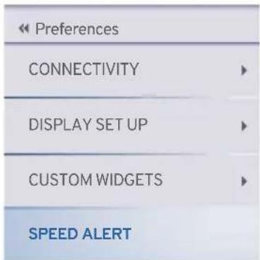
- Press the UP button to increase the over speed indication and the DOWN button to reduce the over speed indication.
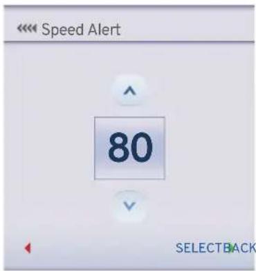
Note
The default speed alert will be set as 60 kmph.
The over speed indication can be set between 50 to 160 kmph in intervals of 10 kmph.
- Speed Alert in red band on status bar and red boundary box around the speed digit will appear and blink as soon as the speed exceeds the set limit.
- Red band & red boundary box will be displayed for 10 seconds.
- If the speed remains more than the set limit even after 10 seconds, the red colored boundary box will blink around the speed digits.
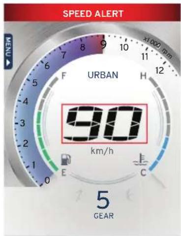
TVS CONNECT APP

Dedicated smart phone app is available in the Google Play and the Apple store for your 'TVS RR310' and it can be installed in your Android and Apple smart phones. To access the features of your TVS RR310's connected TFT instrument cluster like :
- Incoming call alerts in connected instrument cluster.
- Battery status of your smart phone in connected instrument cluster.
- "Do Not Disturb" mode during the ride (applicable only for Android smart phones).
- To send navigational assist instructions inputs to the connected instrument cluster from your smart phone.
- To store Digital documents such as Driving license, RC copy, Aadhar card etc. in TVS Connect App and transfer same in instrument cluster
• To save the last traveled route.
• To locate the last parked location of your TVS RR310.
• To know the signal strength of your mobile network in connected instrument cluster.
• To generate and store Ride reports.
- To sync the connected instrument cluster clock with smart phone clock.
- Try to avoid use the navigation feature while riding as a safety measure.
This dedicated mobile app of your TVS RR310's can be downloaded from the Google Play and the AppStore® by searching the key word 'TVS CONNECT' else by scanning the below QR code.


Android IOS

Caution
While using the navigation feature, ensure you do not look at the speedometer for long as it might lead to an accident.

Note
This smart phone app is compatible only for the smart phones with Android OS version 8 and above, iOS version 11 and above and the BLUETOOTH version 4.0 and above. Android and Google Play are trademarks of Google LLC. App Store® and iOS are trademark of Apple.
If any issues with connectivity features please approach TVS Motor Company Authorised Main Dealer
How to login
On opening the TVS CONNECT app the following introductory screens will be displayed.

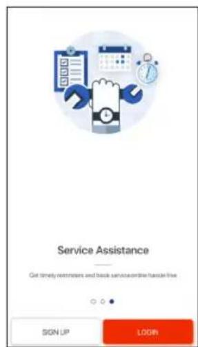
Move to the last screen where you will find the 'SIGN UP' and 'LOGIN' tab. If you are having login already then press login tab. A screen with various login options opens-up as shown.
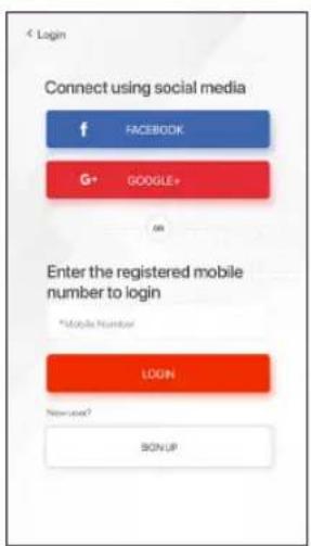
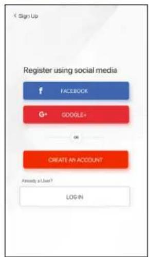
You can login using your social media logins like FACEBOOK and GOOGLE+ or using your mobile number which has been registered already.
If you are a new user then press the sign up tab where you will find various options for registering using your social media logins like FACBOOK and GOOGLE+ or a tab for creating new account.
Using your social media logins you can create new login else press the 'CREATE AN ACCOUNT' tab.
TVS Racing
On pressing the 'CREATE AN ACCOUNT' tab, a screen opens with various input details. Feed in your details and submit. On submitting the details a screen opens with one time password (OTP) entry.
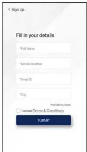
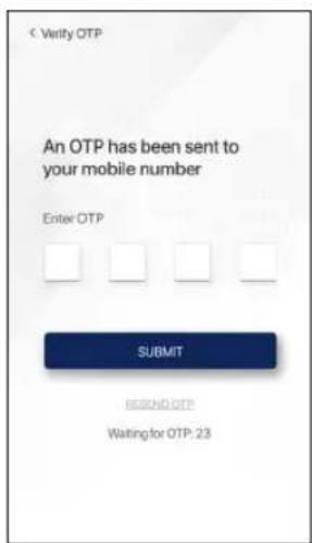
Enter the OTP which is received from TVS Motor Company Limited and submit. On submitting the OTP, another screen opens where you have to enter your vehicle's chassis number for verification.
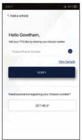
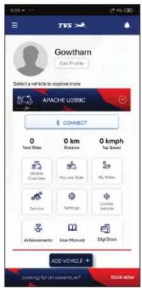
After successful verification of your chassis number, the Home screen of the app opens.
TVS Racing
Note
Please remember that the navigation license has to be renewed after 5 years of vehicle purchase and renewal can be done by contacting near by TVS Motor Company Authorised Main Dealer.
TVS Racing
First time Bluetooth paring:
To pair your Android smart phone or iPhone with your TVS RR310's connected instrument cluster, via Bluetooth, for the first time.
- In order to pair device, select "preferences" in 'menu' by navigating to connectivity paired device.
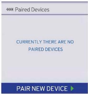
- Press down button and press the set button to pair a new device.
-
Once a device is selected the new paired device icon will blink.
-
Ensure that switch ON bluetooth in your mobile device
- During the pairing, the bluetooth symbol 'flashes in the connected TFT instrument cluster.
- OpentheTVS Connect app and press "CONNECT", ensure the smart phone is near to the vehicle.

- Press and hold "CONNECT" for 2 sec to erase previous vehicle details and connect with a new vehicle in the TVS connect app.
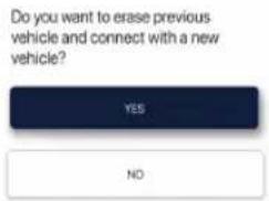
- In connected TFT instrument cluster Bluetooth name is prefixed by TVSRR310 and followed by alphanumeric digits. Ex : 'TVSRR3100000000'.
- Now, select the 'TVSRR3100000000' in app to initiate the pairing process.
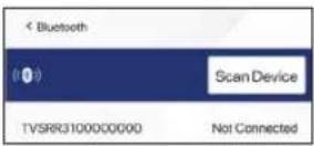
- Passkey will be display in the Connected TFT instrument cluster as shown.
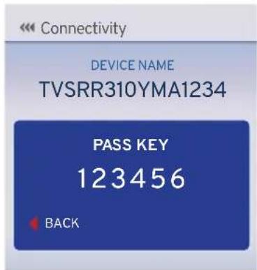
- Now, enter pass key '123456' in app to initiate the pairing process.
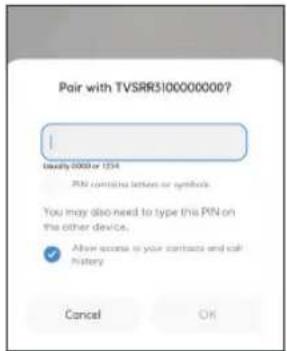
- On pairing, connected TFT instrument cluster displays 'CONNECTION SUCCESSFUL' message is display.
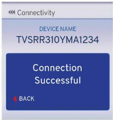
- Once device paired the Bluetooth 'icon phone's battery ' icon and signal strength ' icons will be displayed on connected TFT instrument cluster.

TVS Racing
Note
During the course of pairing process, if there is any occurrence of error, the connected instrument cluster should be turned 'OFF' and 'ON', and the application also need to be restarted.
Please remember that, all the smart phones are not compatible for pairing with the TVS RR310's connected TFT instrument cluster.
During the search of Bluetooth devices in app, if the vehicle connected instrument cluster's Bluetooth device ID is not visible, try for one or two more iterations.
In your motorcycle only five devices can be added. To add a 6th device, delete any one paired device and try pairing a new device.

Note
Only one iPhone can be auto-paired with a single instrument cluster at a time. If the user need to connect multiple iPhones with the single instrument cluster, the previous connected iPhone has to be forgotten by clicking, "Forget This Device" from Bluetooth settings in the iPhone.
If the vehicle battery is reset or fuse is blown, then too "Forget This Device" from Bluetooth settings in the iPhone has to be done.
Steps to "Forget This Device" in iPhone:
If the user needs to connect multiple iPhones with the single instrument cluster, the previous iPhone has to be forgotten using "Forget This Device" from Bluetooth settings in the following manner:
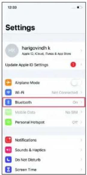
- In the previous connected iPhone, open the SETTINGS -> BLUETOOTH.
- Select the instrument cluster, which was connected previously.
- Click on the "Forget this device".

Auto pairing
Once the first time pairing is done between vehicle's connected TFT instrument cluster and your smart phone, the phone will automatically pair with the vehicle when the following conditions are met :
- Auto connect will happen after pairing only if app is opened in the mobile and connect button is pressed on the App.
- If the ride is on going and the rider does ignition lock OFF and then ignition lock ON, then app gets auto connected and ride will continue on App until user ends the ride.
- Once the rider ends the ride, to start a new ride he has to press connect button in the app.
Caution
In certain Android phones auto pair functionality does not work after first time pairing due to compatibility with various OS versions.

Note
If the phone enters battery saver mode, auto-pairing might not happen. It takes maximum of five minutes for auto-pairing and it can happen in vehicle running or engine at idling or engine off condition.
Auto-pairing happens only if the application is locked in the RAM in multitasking screen of the phone with manufacture's customized OS (Ex : MI, Vivo etc.)
In case of Android phones with Android OS version above 8.0, for App to work seamlessly, any battery optimization setting to be removed in the TVS Connect App and GPS shall be allowed to run in background in high accuracy mode.
Even if your phone's Bluetooth is already paired to other gadgets like smart watch, health band or helmet, the auto-paring works with your TVS RR310's connected instrument cluster.
If the application unfortunately stops due to unforeseen circumstances, close and reopen the application and do the manual pairing for the first time, then auto pairing will happen subsequently.

Note
Once the connected instrument cluster of your TVS RR310 is connected with your smart phone, the connected instrument cluster displays Bluetooth ' * icon, your mobiles battery level ' 📋 ' icon and network providers signal strength ' 📁 ' icon.
Incase multiple SIM cards are used in smart phone, by default, SIM 1's network provider's signal strength is shown in the display of connected instrument cluster.
Signal strength displayed in connected instrument cluster might vary from the display in smart phone as the former is referred from telephonic standards.
TVS Racing
Digital locker
Digital locker is used to transfer the images or documents such as driving license, RC book, Aadhar card etc. from the TVS Connect app to TFT Instrument cluster using both Android and iOS mobile phones. Follow the below steps to upload the image form gallery or camera to the TVS Connect app.
- Open TVS Connect app.
- Click Digi Docs icon.

- Clicks LET'S GO icon.
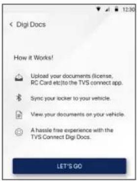
- Select image from gallery or camera.
- After selecting the documents, press 'Sync locker to vehicle' button to connect TVS Connect app and start document transfer
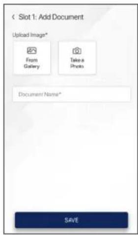
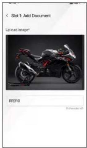
Now the image is ready to transfer to TFT Instrument cluster. Once the TVS Connect app is connected to TFT Instrument cluster the synchronization starts automatically.
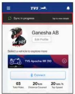
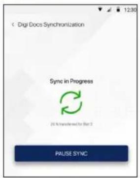
The synchronization can be paused by clicking 'PAUSE SYNC'.
Synchronization can be resumed by clicking 'RESUME SYNC'.
Note
Total of 3 documents can be stored in the TFT Instrument cluster.
Time to transfer one image without loss of data around 12 minutes.
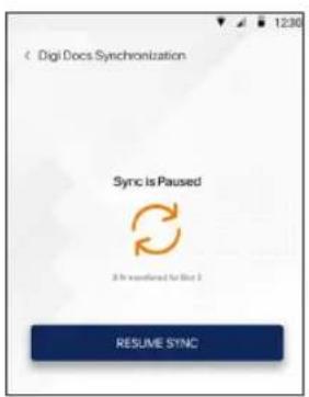
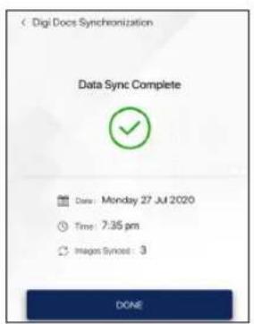

Note
This section shows the position and operation of the major components of your motorcycle.
Major Components (ref. Fig. 22)
1) Cooling system (radiator) (ref. page 93)
2) Fuel tank cap (ref. page 95)
3) Seat lock (ref. page 99)
4) Adjustable rear suspension* (ref. page 98)
5) Coolant reservoir (ref. page 93)
6) Adjustable front suspension* (ref. page 98)
* Applicable for Apache RR 310 BTO version
# Hidden items are marked with dotted lines
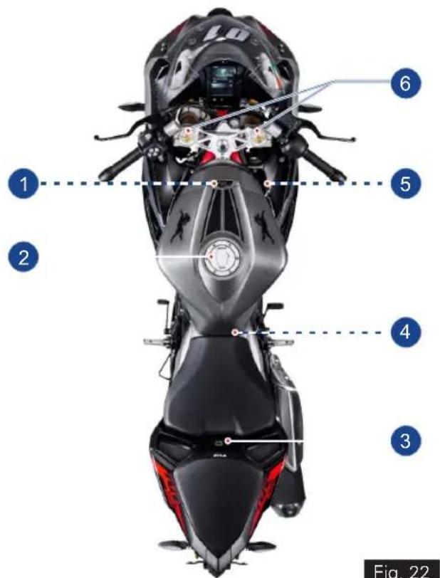
Fig. 22
Cooling System (Radiator) (ref. Fig. 23)
A coolant is used in the motorcycle cools the hot engine and ensures that operating the vehicle at specified temperature which in-turn avoids the risk of malfunctions.
- A radiator and cooling fan fitted in the cooling system does job of cooling the coolant used in the motorcycle by air stream.
- Dirty cooling foils of radiator reduces the cooling effect. Do the visual check and ensure the cooling foils of the radiator are not clogged with any dirt or mud. If so contact TVS Motor Company Authorised Main Dealer.
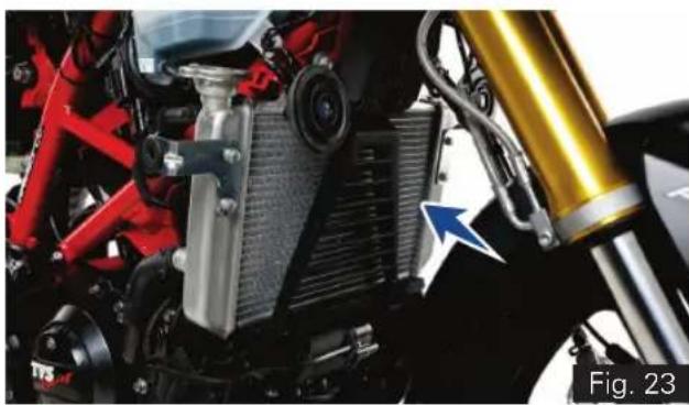
natural_image
Close-up of a motorcycle's internal components, including red and black parts, heat exchangers, and a yellow mechanical bracket (no visible text or symbols)A coolant reservoir tank (A) is fitted on the right side of the motorcycle below the side panels (ref. Fig. 24).
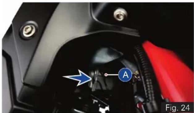
natural_image
Close-up of a motorcycle's engine compartment with a blue arrow pointing to component A (no text or symbols on the main body)Note
The cooling fan may switch ON approx 22 secs. after the ignition is turned OFF to reduce the heat and to protect the engine which is normal. Need not panic.
- Visually inspect the coolant level in the tank (use a torch if required).
- The coolant level should be between minimum and maximum level(1&2)onthetank (ref. Fig. 25).
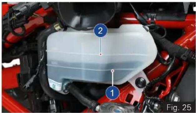
natural_image
Close-up of a red automotive engine compartment with numbered components (1 and 2), no visible text or symbols on the main body.- Contact TVS Motor Company Authorised Main Dealer for topping-up if the level in the tank is lower than the minimum level.
Warning
Coolant is poisonous and health hazard. Avoid contact between coolant and body or clothing incase if you are handling it.
Caution
Use only recommended coolant (Glycentine G48, Coolant + Water; @ 50:50 ratio; total filling 1 litre). Use of improper coolant may cause damage, such as corrosion in the engine parts, blockage of the cooling passage or radiator and premature wear of the water pump seal.
Do not use tap water, or mineral water while topping-up the coolant.
Fuel Tank Cap (ref. Fig. 26)
This motorcycle is equipped with a lockable fuel tank cap (A).
To open:
- Lift the protection lid (B).
- Insert the control key into the lock. Rotate the key a 1/4 turn clockwise and lift the cap.
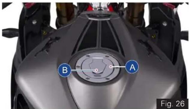
To close:
- Push the cap down into its seat until hearing a click sound.
- Turn the key anticlockwise to the initial position and remove it.
- Close the protection lid.
Refueling (ref. Fig. 27)
- Never overfill the tank when refueling. The fuel level always be below the brim of the fuel tank neck (A).
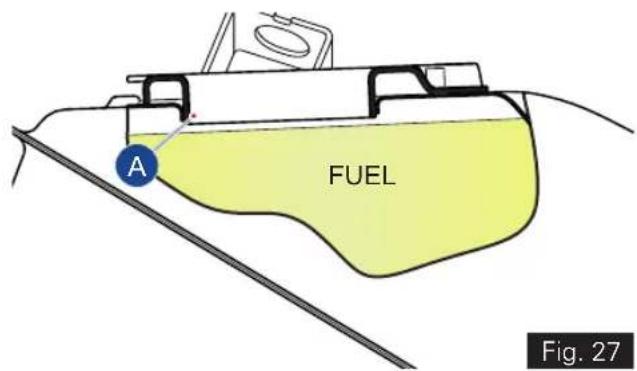
* The fuel tank is not a measuring instrument and the capacity of the fuel tank may slightly vary from the indicated capacity.

Warning
Do not smoke while refueling. Do not use cell phones while refueling. Avoid spilling of fuel on hot engine. Refill petrol in well ventilated area. Switch OFF the engine and ignition key while refueling as petrol is highly inflammable. Be sure there is no fuel trapped in the filler recess. To avoid evaporation of petrol and deterioration of paint gloss due to ultra violet rays and heat of sunlight, always park your motorcycle in a covered parking.

Caution
Check for abnormal jerk / noise while opening the cap / leak. If found any, contact TVS Motor Company Authorised Main Dealer.

Note
After ignition ON, the instrument cluster checks for multiple parameters. Side stand status is one of such parameters. If the side stand is engaged, then the fuel level indication indicates the previously stored value. Once the side stand is dis-engaged, the fuel level display gets updated if there is any change in the volume.
Always make sure to close the cap properly after every refilling to avoid leak / evaporation.
Side Stand (ref. Fig. 28)
Side stand (A) can be operated with your foot. To support your motorcycle on side stand:
- Hold the motorcycle handle bars with both the hands and push down the stand with your foot until the stand is fully extended.
- Lean the motorcycle to the left until the stand contact the ground.
- To move back the side stand to its original position (horizontal position), tilt the motorcycle to the right and, at the same time, lift the stand with your foot.
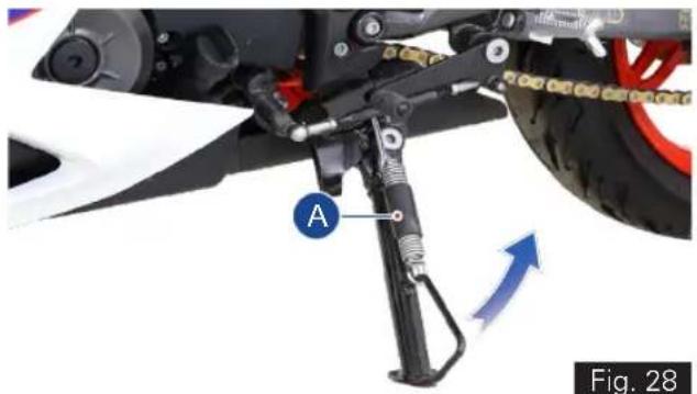
natural_image
Mechanical assembly diagram showing a mounted gear and wheel components with labeled parts (A), no readable text or symbols beyond labels
Caution
Before supporting the motorcycle on side stand, make sure that the supporting surface is hard and flat. Do not park the motorcycle on soft ground, gravel etc., else the bike may fall down.
While parking the motorcycle in downhill tracks, always park the bike in such a way that the rear wheel of the bike facing downhill.
Ensure not to disturb the side stand switch setting.

Warning
Do not sit on the motorcycle when it is supported on side stand.
Adjustable suspension\*
Adjustable front suspension (ref. Fig. 29)
Your motor cycle is fitted with adjustable front suspension to meet different load and driving conditions.
- The compression damping force and rebound damping force of the front suspension can be adjusted to suit your requirements. Refer page 113 for adjustment procedure.
- Inspect for any fluid leak in the inner tube of the front suspension
- If any leak is found contact TVS Motor Company Authorised Main Dealer.
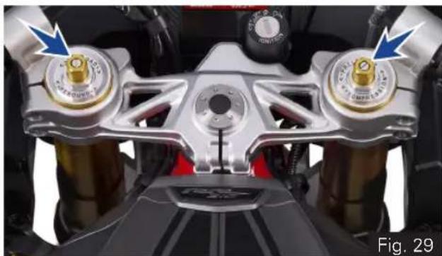
natural_image
Close-up of a motorcycle front panel with two metallic components and blue arrows pointing to specific parts (no text or symbols visible)Adjustable rear shock absorber (ref. Fig. 30)
Your motor cycle is fitted with adjustable gas filled rear shock absorber (A) to meet different load and driving conditions.
- The rebound damping force of the shock absorber can be adjusted to suit your requirements. Refer page 116 for pre-load adjustment procedure.
- Inspect the shock absorber for any dirt or mud accumulation on it or any fluid leak.
- If found any, clean them properly using a soft cloth and brush.
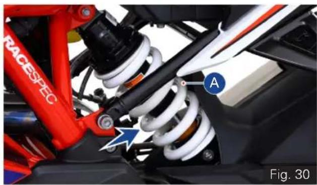
natural_image
Close-up of a red racing suspension system with visible springs and components, labeled 'RACESPEC' and marked point 'A', no readable text or symbols beyond labels.* Applicable for Apache RR 310 BTO version
- If any leak is found contact TVS Motor Company Authorised Main Dealer.

Note
During time of delivery of the motorcycle, the rear shock absorber is adjusted to the standard configuration.
Seat Lock (Rider and Pillion Seat)
This motorcycle is equipped with a lockable rider and pillion seats. The seat lock (A) is located between the rider and pillion seat as shown (ref. Fig. 31)
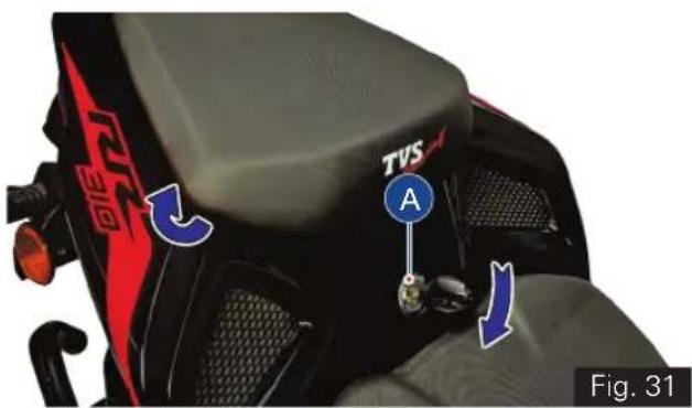
To open pillion seat:
- Insert the control key into the seat lock. Rotate the key in clockwise until the lock is released.
- first, slide the seat towards vehicle front direction.
- Ensure the hook underneath got released from frame and take out the seat.
To close pillion seat:
- Slide the rear end of the seat bottom underneath the frame hook.
- Locate the seat lock pin into seat lock latch and gently press (at the front end).
- Finally ensure that the seat is fastened securely to the frame.
To open the rider seat:
- Remove the pillion seat as explained earlier and take out the control key from the seat lock without fail.
• Take off the tool kit from the storage (ref. Fig. 32)
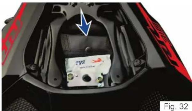
natural_image
Interior view of a vehicle's head and engine compartment showing battery pack and red warning stripes (no readable text or symbols)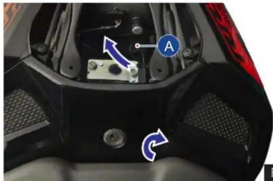
natural_image
Close-up of a motorcycle's front wheel and engine compartment with labeled parts (no readable text or symbols)Fig. 33
- Pull the seat release cable (A) to release the seat lock (ref. Fig. 33).
- Keeping seat release cable pulled, lift the seat from rear and slide it backward.
To close the rider seat:
- Slide the front end of the seat bottom underneath the frame hook.
- Locate the lock pin of the seat into seat lock latch and gently press at the rear end.
- Finally ensure that the seat is fastened securely to the frame.

Caution
Take the control key out from the seatlock without fail during the removal of rider seat, to avoid damage to the seat / lock.
Make sure that the seats are locked securely in position after reassembly.
Running-in is essential to preserve engine life and performance over time. Keeping to the running-in recommendations will ensure longer engine life and reduce the need for overhauls and re-tuning. Refer page 01 for running-in information.
Before Riding
- Ensure that tyre pressure is as per specification. Lower or higher tyre pressures are likely to cause instabilities in motorcycle behaviour.
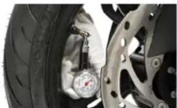
natural_image
Close-up of a car tire being adjusted for pressure, with a hand adjusting the tire (no visible text or symbols)- Check operation of throttle, clutch, and brakes as well as free play on front and rear brakes. Pump in the brake lever and pedal a few times to ensure proper bleeding.

natural_image
Close-up of a hand wearing an orange and black glove with cartoon eyes (no text or symbols visible)- Check both tyres for any wear or abnormalities. Ensure that wear is not below 'Tread wear indicator' mark.
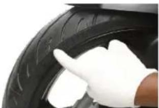
natural_image
Close-up of a hand in white gloves touching the tire (no visible text or symbols)- Check steering freeness, front and rear wheel freeness and alignment.
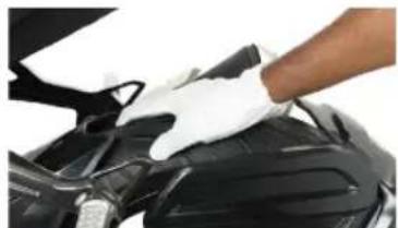
natural_image
Close-up of a gloved hand adjusting the hood of a car engine (no visible text or symbols)TVS Racing
- Check tightening of wheel axle nuts, swing arm nut and steering nut.
•
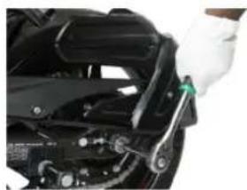
natural_image
Close-up of a hand using a wrench to adjust or install a mechanical component (no visible text or symbols)- Also check tightening of front fork and shock absorber mounts.
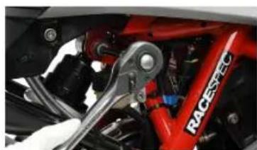
natural_image
Close-up of a red RACEPEC bicycle wheel with a wrench, no visible text or symbols on the vehicle itself.- Check for chain slackness as per specification.
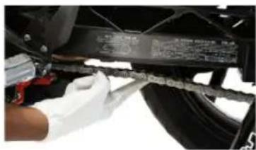
natural_image
Close-up of a gloved hand adjusting a mechanical component with a ruler and attached parts (no visible text or symbols)- Adjust mirror position to have optimum rear visibility. If you prefer track riding sans rear view mirrors, please remove and preserve them carefully.
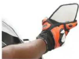
natural_image
Close-up of a hand wearing a black and orange athletic glove with white highlights (no text or symbols visible)
Warning
Failure to carry out these checks before riding may result in damage to the motorcycle and injury to the rider.
TVS Racing
- Check engine oil, brake oil and coolant oil levels.
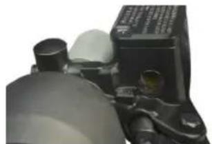
natural_image
Close-up of a mechanical component with cylindrical and flanged parts (no visible text or symbols)While Riding
- Wear all necessary safety gears (Helmet, Jacket, Knee guards, Shoes and Gloves) before riding.
natural_image
Person standing beside a motorcycle with racing gear (no visible text or symbols)- Riding Posture - While riding, sit slightly behind the fuel tank. Body position should be relaxed such that back is very comfortable. Shoulders and arms should also be relaxed with slight bend in the arm as shown. Hold the handle bar with a good grip. Fuel tank should be firmly held by the thighs while riding. This will help maintain stability of the bike at all speeds.
natural_image
Person riding a black and white motorcycle with helmet and gear (no visible text or symbols)- While riding, have a relaxed posture with wide vision.
- Ensure smooth operation of throttle, do not abruptly open the throttle especially in the corners
- Don't throttle while entering a turn. You may accelerate progressively while exiting a turn.
-
Do not shift gears in a turn.
-
Avoid abrupt hard braking, If hard braking is inevitable, release throttle and apply front and rear brakes in a progressive manner.
- Don't brake too hard while the vehicle is leaning, as vehicle may skid easily.
- Tyre grip reduces in cold conditions. It will take about 5 kms of riding for tyres to reach optimal temperatures.
- New tyres require running in for 20 kms before you can get the maximum grip.
Starting the Engine
Warning
Before starting the engine, familiarise your self with the controls which you need to use while riding (ref. page 20).
- Turn-on the ignition key (ref. page 21). Ensure that the neutral indicator 'N' (C4, ref. page 34) is ON.
- Check that the engine cut-off switch is positioned at run mode '○' and press the starter button '(ref. page 29).
Note
It is possible to start the vehicle with the side stand ON and gear box in neutral. When starting the bike with the gear engaged, apply the clutch (the side stand must be up in this case).
If the battery voltage is too low, the system automatically disables the self-start function.
Caution
Do not rev the engine when it is cold. Allow some time for the oil to warm up and to reach all points that needs lubrication.
Moving the Vehicle
- Disengage the clutch by pressing the control lever.
- Press the gear shift pedal downwards with the tip of your foot to engage the first gear.
- Increase the engine speed by turning the throttle twist grip while gradually releasing the clutch lever; the motor cycle start moving forward.
- Release the clutch lever and increase the engine speed (increase the throttle).
- To up shift the gear, close the throttle to slow down the engine speed, disengage the clutch, lift the gear shift pedal up and release the clutch lever.
- To down shift the gear, proceed as follows: release the throttle twist grip, pull the clutch lever, increase the engine speed for a moment to allow the gears to synchronise, down shift the gear and release the clutch lever.
- Use controls wisely and promptly: when riding uphill do not hesitate to down shift the gears as soon as the vehicle tends to slow down. This will avoid stressing the vehicle and the engine abnormally.
Caution
Avoid sudden acceleration, as this may lead to misfiring, improper engagement of transmission (snatching).
Do not pull the clutch lever longer than necessary after engaging the gear. Otherwise the friction plates in clutch may get overheat and wears out quickly.
Braking
- Slow down the speed in right time, shift down the gear to use the engine brake, then apply both the brakes.
- Pull the clutch lever before stopping the motorcycle to avoid sudden stoppage of engine.

Warning
Use both front and rear brake for effective braking.
When riding in the rain or on slippery surfaces, braking capacity is significantly reduced. Always use the brakes very gently and carefully when riding under these conditions.
When riding downhill, shift down to the lower gears to use engine as a brake.

Caution
Keeping the brake applied continuously causes the brake pads (friction materials) to overheat and reduces the braking effectiveness which is dangerous.
Stopping the motorcycle
- Reduce speed, close the throttle and down shift the gears. Bring the transmission to neutral position just before the vehicle stops.
- Apply the brakes and bring down the motorcycle to complete stop.
- Turn OFF the ignition.
Parking
- Stop the motorcycle. Place it on the side stand on a flat firm surface (ref. page 97).
- Turn the steering all the way to 'left' or 'right' and lock as explained in page 20. Take out the control key from the ignition lock.
- If the vehicle is parked in a garage or other indoor area, make sure that there is a proper ventilation and the motorcycle is not nearer to a source of heat.

Note
You may switch ON the hazard lamps if the vehicle is parked in hazardous location. Refer page 24 for hazard lamps function.

Warning
The engine and the exhaust system might be very hot even after switching OFF the engine. Care should be taken not to touch the exhaust system with any part of your body.
Park the vehicle in a place where the pedestrians or children are not likely to touch the hot surface. Do not park the vehicle near dry grass or any other flammable resources which might catch fire.
Using padlocks or other locks like brake disc locks, rear sprocket locks etc. to prevent the movement of the motorcycle is very dangerous and may affect the motorcycle operation and safety of the users.
Fuel Recommendation
Use only BSVI ES Gasoline.
BS VI petrol containing upto 20% of ethanol by volume can be used.
Higher ethanol content in petrol can lead to
- degrade plastic and rubber components of fuel system and vehicle parts
- cause corrosion damage to metal parts like fuel tank, etc.
- result in startability & drivability issues
- decrease fuel economy
Ethanol absorbs water very easily, resulting fuel separation. Extra care shall be taken to prevent moisture entry into fuel tank while filling ethanol blended petrol and water washing of vehicle.
Painted parts (viz. panels, covers) shall not come in contact with ethanol blended fuels.
Manufacturer is not responsible for any warranty issues that results from using ethanol blend in excess of 20% by volume in petrol.
In case of any abnormalities observed due to use of ethanol blended fuels, customers are advised to use a different fuel station / brand for standard E20 fuel or contact authorised service centres.
- Refer page 95 for fuel filling procedure.

Caution
Never mix oil in the petrol. Always fill fuel from reputed and reliable fuel stations.

Note
Use fuel additives in petrol (as recommended by additive manufacturer) for low carbon deposition.
Checks and Tips for Better Fuel Economy
- Carry out the periodic maintenance checks as specified in this manual (ref. page 123).
- Regular maintenance checks will save fuel while ensuring trouble-free, enjoyable and safe riding besides keeping the environment clean.
- A dirty defective spark plug leads to wastage of fuel due to incomplete combustion.
- Replace the spark plug every 20000 km. Use recommended plug only.
- A dirty air cleaner element restricts airflow and reduces fuel economy.
- Replace the air cleaner element every 10000 km.
- Increase in engine rpm during acceleration, without increase in road speed indicates the clutch slip. A slipping clutch causes high fuel consumption and engine overheating.
- Adjust the clutch play as explained in page 132 if the above malfunction is observed.
-
If the condition persists even after adjusting the clutch play contact TVS Motor Company Authorised Main Dealer.
-
Dirty or less engine cum transmission oil increases the friction between various parts of the engine and reduces engine life, and increases the fuel economy.
- Inspect the engine cum transmission oil level as explained in page 130 and top-up if necessary.
- Engine cum transmission oil should be replaced as per the maintenance schedule without fail.
- Always use recommended engine oil only (ref. page 177).
- Low tyre pressure has adverse effects on the vehicle. The drag on the vehicle increases resulting in decreased fuel economy. Further more handling may be affected adversely.
- Check tyre pressure regularly and inflate them to recommended pressure. (ref.page 137).
- Never use tyre which are worn-out beyond the permissible limit.
- Check and ensure the drive chain slackness. Excess slackness lead to higher fuel consumption (ref. page 141).
- Check and ensure the free movement of wheels by rotating them to avoid wastage of fuel.
TVS Racing
- A racing start from rest at full throttle will waste fuel and damage the engine. It is also creates potentially hazard traffic situation.
- Fuel is wasted whenever the rider suddenly accelerate or apply brake.
- While waiting for someone or stopping in signals for long time, if the engine is kept running at idle speed, leads to unnecessary wastage of fuel.
- Anticipate corners and slopes as well as the traffic conditions. Unnecessary and frequent braking reduces the fuel economy.
GENERAL ADJUSTMENTS
TVS Racing
Rear View Mirrors LH & RH (ref. Fig. 34)
Adjustable rear view mirrors (LH & RH) are provided with your bike. These mirrors can be adjusted to your convenience by following the procedure given below:
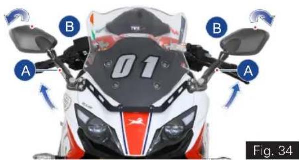
- Move the rear view mirror stem (A) to the desired position (forward or backward).
- Tilt the mirror portion (B) till the clear vision is obtained (up or down).

Caution
Never try to adjust the mirror position by mirror portion (B) this could break the mirror.
Gear Shift Pedal Position Adjustment (ref. Fig. 35)
The position of the gear shift pedal (A) in relation to the foot rest can be adjusted to suit the rider's requirement.
To adjust the gear shift pedal position:
- Using an open end spanner hold the gear shift pedal link rod (1) on the flat surface of the rod.
- Using another open end spanner completely loosen the lock nuts (2 & 3).
- Now, turn the gear shift pedal link rod (1) 'in' or 'out' until the desired pedal position is set.
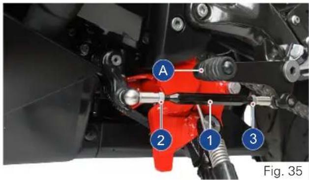

- After obtaining the desired position, re-tighten the lock nuts (2 & 3) holding the link rod (1) in position.
- Ride the vehicle and ensure the gear shift is easy and convenient.

Note
Lock nut (2) has a left-hand thread and should be loosened or tightened in opposite direction.

Caution
Do not loosen the link rod to the maximum position (till the last thread). Else, it may come out from the shifting mechanism during ride.
ADJUSTABLE SUSPENSION\*
Front fork adjustment

Note
Always set the spring loads in both fork legs equally, to obtain optimum suspension performance.
Each Fork leg is provided with a spring PRELOAD adjusting bolt, the right leg is provided with a COMPRESSION damping force and left leg is provided with REBOUND damping force, through damping adjuster screw.
Spring preload
Increasing the spring preload will harden the suspension. To decrease the spring preload, thereby soften the suspension. Turn the bolt as indicated in the Fig 36.
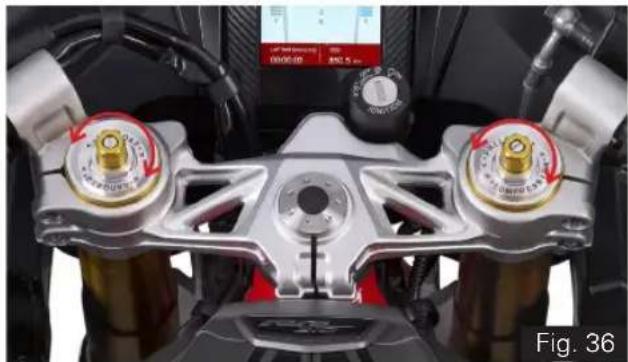
natural_image
Close-up of a motorcycle front-mounted climate control panel with two rotary gauges and a digital display (no readable text or symbols)The spring preload setting is determined by the distance A or no of groove, Shorter the distance A or no of groove indicates higher preload by rotating the preload adjusting bolt clockwise, higher the distance A or no of groove indicates lower preload rotating the preload adjusting bolt anti-clockwise.
TVS Racing
1st groove - hard suspension

natural_image
Golden cylindrical object with a small protrusion on top (no text or symbols visible)5^th groove - Standard position
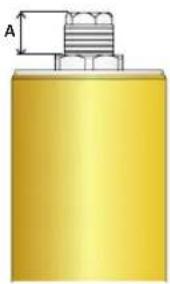
natural_image
Pure diagram of a yellow cylindrical object with a threaded top and dimension label A (no text or symbols)7 ^th groove - soft suspension
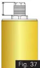
natural_image
Yellow cylindrical object with a metallic threaded top and a small bracket, labeled 'Fig. 37' (no other text or symbols)| Spring Preload | Distance 'A' (in mm) | Groove position |
| Standard 14 5 | ||
| Maximum 4 1 | ||
| Minimum 19 7 |

Caution
Do not attempt to over-tight the adjuster bolt, beyond the maximum and minimum position, to prevent internal damage.
Compression damping force
The compression damping force adjustment is provided in the right leg only.
To increase the damping turn the adjuster screw clockwise and to reduce the damping turn the adjuster screw towards anti-clockwise, as shown. (ref. Fig. 38)
During adjustment count the numbers of clicks from fully closed (clockwise) position.
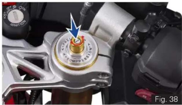
natural_image
Close-up of a motorcycle's internal combustion engine component with a blue arrow pointing to the dial (no text or symbols visible)* Applicable for Apache RR 310 BTO version
Rebound damping force
The rebound damping force adjustment is provided in the left leg only.
To increase the damping turn the adjuster screw clockwise and to reduce the damping turn the adjuster screw towards anti-clockwise, as shown. (ref. Fig. 39)
During adjustment count the numbers of clicks from fully closed (clockwise) position.
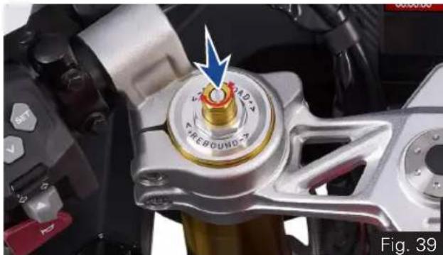
natural_image
Close-up of a mechanical component with a central rotary knob and blue arrow indicator (no readable text or symbols)Note
When Adjusting the damping force setting turn the adjuster screw in clockwise direction until it stops, noting that the first click counted as 1 then count the clicks turning in anti-clockwise direction.
Although the damping adjuster may turn beyond the stated minimum settings, such turns are ineffective and advised not to turn further, as it may lead to the damage of damping mechanism.
Rear shock absorber's adjustment (ref. Fig. 40)
Pre-Load Adjustment
The pre-load of rear shock absorber can be adjusted as per rider's convenience and the load (weight of rider, passenger and luggage) on the vehicle.
There are 10 notches (1) for adjusting the pre-load of the shock absorber. Normally, the shock absorber's pre-load adjuster (2) will be positioned at 3rd notch (standard setting).
Increase the spring pre-load (shift to higher notches) for heavier rides.
Decrease the spring pre-load (shift to lower notches) for lighter rides.
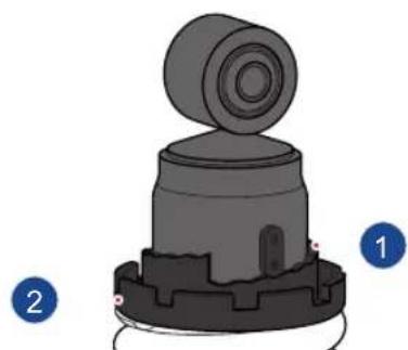
natural_image
3D mechanical component diagram showing a cylindrical top with a flanged base and labeled parts 1 and 2 (no text or symbols on the component itself)Fig. 40
TVS Racing
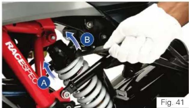
To adjust the shock absorber's pre-load:
- Place the motorcycle on its stand on a firm and flat surface.
- Locate the adjuster shock absorber rear and handle ring spanner of tool kit (ref. page 162) properly into the notches of pre-load adjuster (ref. Fig. 41).
- Carefully rotate the adjuster clockwise (A) to increase the pre-load (hard suspension).
- Else, rotate the adjuster in anti-clockwise (B) to decrease the pre-load (soft suspension).

Warning
The rear shock absorber contains highly compressed gas. Do not try to open or disassemble it in any way.
Take a special care while turning the pre-load adjuster because, your hand may be striking against the other parts of the motorcycle if the adjuster spanner slips out of the pre-load adjuster notch.

Caution
Rear shock absorber to be adjusted only on the left side of the vehicle.
Adjust step by step (3rd to 4th notch and so on). Do not go at a stretch as it will damage the adjuster.
Rebound damping*
The shock absorber is provided with rebound damping force adjustment.
To increase the damping turn the adjuster screw clockwise and to reduce the damping turn the adjuster screw towards anti-clockwise, as shown. (ref. Fig. 42)
During adjustment count the numbers of clicks from fully closed (clockwise) position.
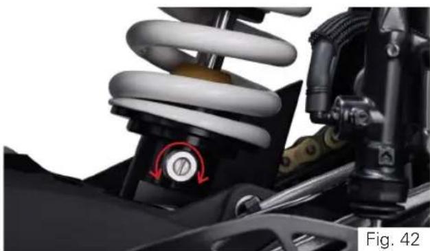
natural_image
Close-up of a car suspension system with visible springs and brake components (no text or symbols)* Applicable for Apache RR 310 BTO version

Note
The motorcycle delivered with adjustable suspension shall be with standard setting, Refer suspension chart for various setting. However the mentioned suspension settings are only a guide Setting requirements may vary for rider weight and personal preferences, for further information contact TVS Motor Company Authorised Main Dealer.
Damping chart
| Setting | Fork RH (Compression) | Fork LH (Rebound) | Shock Absorber (Rebound) |
| Standard | 10 10 10 | ||
| Solo (Race Track) | 7 2 2 | ||
| Solo (Comfort) | 12 9 8 | ||
| Rider & Pillion | 8 10 10 | ||
| Rider & Luggage (Touring) | 10 10 10 | ||
| Rider, Pillion & Luggage (not exceeding the limits) (Touring) | 7 7 10 |
Spring preload chart
| Setting | Fork RH (Compression) | Fork LH (Rebound) | Shock Absorber (Rebound) |
| Solo (Race Track) | Standard Standard | Standard ( 3^rd notch) | |
| Solo (Comfort) | Standard Standard | Standard ( 3^rd notch) | |
| Rider & Pillion | Standard Standard 4 | ^th notch | |
| Rider & Luggage (Touring) | Standard Standard | Standard ( 3^rd notch) | |
| Rider, Pillion & Luggage (not exceeding the limits) (Touring) | Maximum Maximum 6 | ^th notch |

Note
Luggage load should not exceed 10kgs.
Head Lamp Aiming
To check and adjust the head lamp focus:
- Place the motorcycle upright in a uniform flat surface while ensuring the head lamp center (A) is 5 meter away from a vertical wall or screen (B). (ref. Fig. 43)
• Inflate the tyres to the correct pressure. - Keeping the motorcycle at right angles to its longitudinal axis switch on the 'Low beam' of head lamp.
Two projector lamps need to be adjusted independently as mentioned below:
a. RH side projector adjustment:
- Mask the LH side projector lamp using a black color cloth.
- Adjust the RH side projector lamp adjuster (C) clockwise (Downward) or in anti-clockwise (Upward) and match the low beam cut-off line to the marking line (D) (500 mm) on a vertical wall or screen. (ref. Fig. 43 & 44)
b. LH side projector adjustment:
- Remove the cloth from LH side projector and mask RH projector lamp.
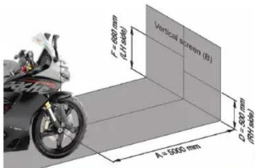
Fig. 43
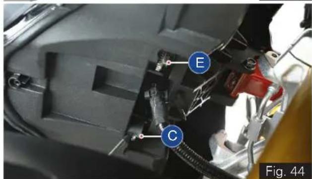
* The specification for head lamp beam adjustment is applicable only for India. Owner's of other countries are advised to adopt the local rules and regulations.
- Adjust the LH side projector lamp adjuster (E) clockwise (Downward) or in anti-clockwise (Upward) and match the low beam cut-off line to the marking line (F) (660 mm) on a vertical wall or screen. (ref. Fig. 43 & 44)
- Both the projectors low beam cut-off line should match with the marked line on the screen or wall.

Note
Head lamp aiming to be done with the unloaded vehicle only.
Both the projector lamps should be adjusted independently.
The adjustment levels mentioned is for solo riding condition. For dual riding condition, the head lamp beam may be adjusted as per need for better visibility.

Warning
Do not stare at LED head lamp beam to avoid damage to the eyes.
MAINTENANCE
TVS Racing
Maintenance Schedule
Maintenance schedule indicates the intervals between periodic services. At the end of each interval, be sure to inspect, check, replace, adjust, lubricate and service as instructed.
If the maintenance service is not done periodically, it will result in rapid wear and severe damage to the vehicle.
If the vehicle is used under high stress conditions such as continuous full throttle operation or rain, is operated in wet or dusty areas, certain jobs should be performed more often to ensure reliability of the vehicle.
Cylinder head, steering components, suspension, chain and wheel components etc. are key items and require very special and careful servicing.
We recommends that the jobs as per the maintenance schedule be performed by your TVS Motor Company Authorised Main Dealer.
Periodic inspections may reveal one or more parts that may need replacement. Whenever replacing any such parts we recommend to use only TVS Motor Company Genuine parts.
Perform pre-ride inspection (ref.page 102) before every scheduled maintenance.
I - Inspect R - Replace T - Top-up
C - Clean A - Adjust L - Lubricate
TI - Tighten
Caution
Proper running-in (ref. page 01) and maintenance is mandatory for making certain that your vehicle is reliable and gives optimum performance at all times. make sure that the periodic maintenance is performed thoroughly in accordance with the instruction given in this owner's manual.
Use of non-genuine spares will affects the performance of the vehicle and failure to comply the warranty claims.
Check for any abnormal jerk during ride / any abnormal noise while opening the fuel tank cap / any leak in the fuel system. If found any, contact TVS Motor Company Authorised Main Dealer.
PERIODIC MAINTENANCE SCHEDULE (months or km whichever occurs earlier) - Free service
| List of operations and type of intervals Service(km or month whichever of the two occurs early) Km x 1000Months | 1st 2nd 3rd | ||
| 1 5 10 | |||
| 2 6 12 | |||
| Engine oil filter along with drain bolt washer R - R | |||
| Air cleaner element -- R | |||
| Spark plug --- | |||
| Tappet clearance (valve clearance)* -- I & A | |||
| Clutch operations (adjust if required) | I & A | I & A | I & A |
| Steering play | I & A | - | I & A |
| Front and rear suspension | -- I | ||
| Wheel bearing freeness (replace if required) | -- I | ||
| Air suction system / engine breather | -- I | ||
| Front fork oil replacement | --- | ||
| All fasteners | I & TI | - | I & TI |
| Drive chain slackness / lubrication | Inspect, adjust and lubricate every 500 km | ||
| Drive chain wear (replace if required) | -- I | ||
* Adjust if necessary
TVS Racing
| List of operations and type of intervals Service(km or month whichever of the two occurs early) Km x 1000Months | 1st 2nd 3rd | ||
| 1 5 10 | |||
| 2 6 12 | |||
| All lamps and horn - | | | |||
| Head lamp beam (focus) | & A | & A | & A | |||
| Battery voltage (recharge if required) | | | | |||
| Brake light switch operation | | | | |||
| Front and rear brake fluid level** | | | | R | |
| Front and rear brake pad wear (replace if required) | - | | | ||
| Disc plates (replace if required) | -- | | ||
| Brake hose / rubber parts of master cylinder and caliper front and rear (replace if required) | -- | | ||
| Tyre air pressure (at cold condition) | I & A | I & A | I & A |
| Steering stem bearing (Inspect & lubricate with Grease if required) | I & L | - | I & L |
| Speed sensor (free from any mud / clogging with dirt) | | | | | ||
| Fuel filter | --- |
** Replace brake fluid first at 10000 kms and every 20000 kms or 2 years thereafter.
| List of operations and type of intervals Service(km or month whichever of the two occurs early) Km x 1000Months | 1st 2nd 3rd | ||
| 1 5 10 | |||
| 2 6 12 | |||
| Coolant level, water hoses and O-rings (replace if required)*** || | |||
| Fuel hose / system I - I | |||
| Swing arm bearing (replace if required) || | |||
| Side stand C, I & L C, I & L C, I & L | |||
| Side stand switch function and physical damage || | |||
| Drive chain guide wear (replace if required) | -- | | ||
| Instrument cluster MIL lamp function | | | | | ||
| Radiator fan / fins and deflector (clean if required) | | | | | ||
| Reading fault codes using diagnostic tool | | | | | ||
| Availability of fuse puller and fuse condition | | | | | ||
| Brake pedal / gear shift lever mounting pin (lubricate using grease) | | | | ||
| Ignition cum steering lock (lubricate using oil) | | | | |
*** Coolant, hoses and O-rings must be replaced every 30000 kms or every 3 years. At higher odometer readings, the above service intervals to be followed.
PERIODIC MAINTENANCE SCHEDULE (months or km whichever occurs earlier) - pay service
| List of operations and type of intervals Service(km or month whichever of the two occurs early) Km x 1000Months | 4th 5th 6th 7th 8th 9th 10th 11th | |||||||
| 15 20 | 25 30 | 35 40 | 45 50 | |||||
| 18 24 | 30 36 | 42 48 | 54 60 | |||||
| Engine oil filter along with drain bolt washer - R - R - R - R | ||||||||
| Air cleaner element - R - R - R - R | ||||||||
| Spark plug - R --- R -- | ||||||||
| Tappet clearance (valve clearance)* | - | I & A | - | I & A | - | I & A | - | I & A |
| Clutch operations (adjust if required) | I & A | I & A | I & A | I & A | I & A | I & A | I & A | I & A |
| Steering play | - | I & A | - | I & A | - | I & A | - | I & A |
| Front and rear suspension | - | - | - | - | | ||||||
| Wheel bearing freeness (replace if required) - | - | - | - | | ||||||||
| Air suction system / engine breather | - | - | - | - | | ||||||
| Front fork oil replacement | - R | -- R -- | ||||||
| All fasteners | I & TI | - | I & TI | - | I & TI | I & TI | - | I & TI |
| Drive chain slackness / lubrication | Inspect, adjust and lubricate every 500 km | |||||||
| Drive chain wear (replace if required) | -- | - | | | - | | ||||||
* Adjust if necessary
| List of operations and type of intervals Service(km or month whichever of the two occurs early) Km x 1000Months | 4th 5th 6th 7th 8th 9th 10th 11th | ||||||
| 15 20 | 25 30 | 35 40 | 45 50 | ||||
| 18 24 | 30 36 | 42 48 | 54 60 | ||||
| All lamps and horn I I I I I I I | |||||||
| Head lamp beam (focus) | I & A | I & A | I & A | I & A | I & A | I & A | I & A |
| Battery voltage (recharge if required) I I I I I I I I | |||||||
| Brake light switch operation | I I I I I I I | ||||||
| Front and rear brake fluid level** | I | R | I | R | I | R | I |
| Front and rear brake pad wear (replace if required) | I I I I I I I | ||||||
| Disc plates (replace if required) | - I - | - I - I | |||||
| Brake hose / rubber parts of master cylinder and caliper front and rear (replace if required) | - I - | - I - I | |||||
| Tyre air pressure (at cold condition) | I & A | I & A | I & A | I & A | I & A | I & A | I & A |
| Steering stem bearing (Inspect & lubricate with Grease if required) | - | I & L | - | I & L | - | I & L | - |
| Speed sensor (free from any mud / clogging with dirt) | I I I I I I I | ||||||
| Fuel filter | - | R | - | - | - | R | - |
** Replace brake fluid first at 10000 kms and every 20000 kms or 2 years thereafter.
| List of operations and type of intervals Service(km or month whichever of the two occurs early) Km x 1000Months | 4th 5th 6th 7th 8th 9th 10th 11th | |||||||
| 15 20 | 25 30 | 35 40 | 45 50 | |||||
| 18 24 | 30 36 | 42 48 | 54 60 | |||||
| Coolant level, water hoses and O-rings (replace if required)*** | | | | | | | | | | ||||||
| Fuel hose / system - I - I - I - I | ||||||||
| Swing arm bearing (replace if required) | | | | | | | | ||||||||
| Side stand C, I | & L | C, I & L | C, I & L | C, I & L | C, I & L | C, I & L | C, I & L | C, I & L |
| Side stand switch function and physical damage | | | | | | | | I | |||||||
| Drive chain guide wear (replace if required) - I - I - I - I | ||||||||
| Instrument cluster MIL lamp function | | | | | | | | | | ||||||
| Radiator fan / fins and deflector (clean if required) | | | | | | | | | | ||||||
| Reading fault codes using diagnostic tool | | | | | | | | | | ||||||
| Availability of fuse puller and fuse condition | | | | | | | | | | ||||||
| Brake pedal / gear shift lever mounting pin (lubricate using grease) | | | | | | | | | | ||||||
| Ignition cum steering lock (lubricate using oil) | | | | | | | | | | ||||||
*** Coolant, hoses and O-rings must be replaced every 30000 kms or every 3 years. At higher odometer readings, the above service intervals to be followed.
Safety Precautions
Before you are starting any maintenance repairs,
- Make sure that engine is in OFF condition. This will help in eliminating several potential hazards like:
- Poisoning from engine exhaust Carbon Monoxide (be sure there is proper ventilation whenever engine is operated in indoor).
- Let the engine and exhaust to cool before working on the motorcycle to avoid burns from hot parts.
- Do not run the engine without instruction for doing the same to avoid injury from moving parts.
- Carefully read the instruction before starting, and ensure that you have tools and skill required for doing the maintenance service.
-
Park the vehicle on a flat firm surface with the side stand, center stand (if available) or the auxiliary stand (paddock stand refer page 163) to prevent the motorcycle from falling while doing the maintenance service.
-
While working on batteries or fuel related items care must be taken to avoid fire or explosion. Use non-flammable solvent only. Keep away the fire (like cigarettes, sparks and flames etc.) from the battery and fuel related items.
- Ensure to remove the head lamp fuse, to avoid battery discharge during working.
Note
We recommend that the maintenance jobs as per the planned maintenance schedule be performed by your TVS Motor Company Authorised Main Dealer. Trained service personals of the Dealer can provide quality, reliable and economical service to your vehicle.
Use only TVS Motor Company Limited Genuine parts for long and reliable life of your motorcycle.
Engine Oil Level
Ensure the safety precautions listed in the page 129 are followed properly.
Check the engine oil level before riding the motorcycle. Insufficient engine oil or too much engine oil affects the engine adversely.
To check the engine oil level, a gauge oil level (dip stick) (A) given on the left side of the crankcase (ref. Fig. 45).
- Wipe off the surroundings of the gauge oil level. Start the engine and let it idle for 3 to 5 minutes.
- Switch OFF of the ignition. Hold the vehicle in upright condition with both the wheels on ground, on a flat and firm surface.
• After 2 to 3 minutes, remove the gauge oil level (A) and wipe it cleanly. - Re-fix the gauge again. Slowly and steadily remove the gauge and inspect the oil level.
- The level should be between minimum (1) and maximum level (2) mark on the gauge (ref. Fig. 46).
- If the level is below the minimum level (1), slowly add recommended engine oil till the level reaches to maximum level (2).
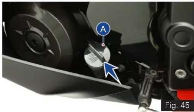
natural_image
Close-up of a mechanical component with a labeled circular component (A) and an arrow pointing to a circular feature, no readable text or symbols present.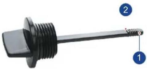
natural_image
Close-up of a black threaded mechanical component with labeled parts 1 and 2 (no text or symbols on the component itself)Fig. 46
• Re-fix gauge after ensuring correct oil level.
- Wipe out the oil traces with a clean cloth to prevent dust accumulation.
- Re-fix gauge after ensuring correct oil level.
- Wipe out the oil traces with a clean cloth to prevent dust accumulation.

Caution
Running the engine with insufficient or excess engine oil may cause serious damage to the engine.
For topping-up, always use TVS Motor Company recommended engine oil only.
Hold the vehicle in upright condition with both wheels on ground, on a flat and firm surface while checking the oil level to avoid wrong indication.
Engine oil and oil filter must be replaced by a TVS Motor Company Authorised Main Dealer at the intervals specified in the planned maintenance schedule without fail. Failing which disqualifies for warranty.

Warning
Correctly recycle or dispose the used engine oil in order to avoid environment pollution.
TVS Racing
Clutch Free Play
Ensure the safety precautions listed in the page 129 are followed properly.
Clutch free play adjustment may be required if the motorcycle gets OFF while shifting from neutral to gear or tends to creep; or if the clutch slips (vehicle acceleration lags behind the engine rpm).
Minor clutch free play adjustment can be done by means of clutch cable adjuster at the clutch lever end.
• Measure the clutch free play (A) at the lever end as shown (ref. Fig 47).
- If the measured free play is 'more' or 'less' than the standard limit given below:
Clutch lever free play 8 to 12 mm
- Remove the cable clamp (1). Pull back the dust cover (2) of clutch lever (ref. Fig. 48).
- Loosen the lock nut (3) and turn the adjuster (4) 'in' or 'out' till the specified play is obtained (ref. Fig. 48).
- After the adjustment, once again check the free play and confirm.
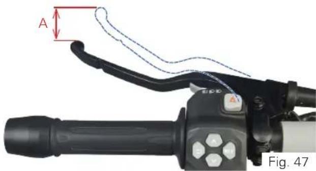
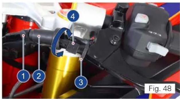
TVS Racing
- Lock the lock nut (3) again.
- If the adjuster is threaded out to its maximum limit or if the correct free play cannot be obtained using the cable adjuster, loosen the lock nut and completely turn-in the clutch cable adjuster.
• Re-fix the dust cover (2) and cable clamp (1). - Loosen the lock nut (5) at the bottom end of the clutch cable (ref. Fig. 49).
- Turn the adjuster in (6) 'in' or 'out' until the specified play is obtained and then tighten the lock nut and check the adjustment once again (ref. Fig. 49).
- After adjusting the clutch play, start the engine and engage the gear. Ensure that the engine is not stalling and not creeping.
- Gradually release the clutch lever while slowly applying the throttle. The vehicle should begin to move slowly and accelerate smoothly. Else contact TVS Motor Company Authorised Main Dealer.
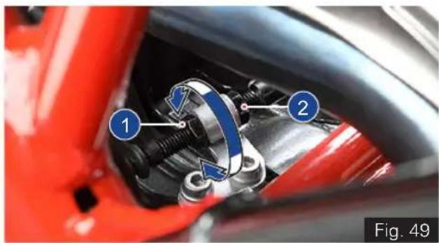
natural_image
Close-up of a red automotive brake caliper assembly with labeled parts (1 and 2), no visible text or symbols beyond labels.
Caution
Clutch play free play should be checked and adjusted only when the engine is cold.
During clutch play checking and adjustment, check the clutch cable for kinks or sign of wear that could cause stickiness or failure.
Lubricate the clutch cable using a cable lubricant available in the market to prevent premature failure and corrosion.
TVS Racing
Brake Fluid Level
Brake fluid level should not fall below the MIN level mark on both front and rear brake fluid reservoir. If the level drops below the limit, air can get into the circuit and make the system ineffective.
Brake fluid must be topped up and changed at the intervals specified in planned maintenance schedule without fail for the proper working and to ensure the safety of the rider.
- Switch OFF and place the vehicle upright on a flat and firm surface using centre stand (if available) or on a auxiliary stand (paddock stand ref. page 163).
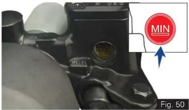
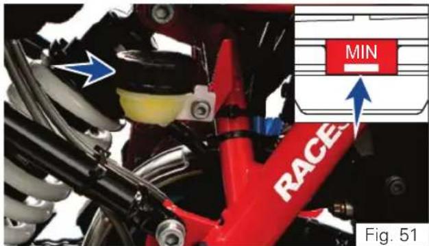
- Keep the handle bar straight.
- Inspect the oil level of both front and rear brake fluid reservoirs (ref. Fig. 50 & Fig. 51).
- If the level is lower than the MIN level mark in any of the reservoir, contact TVS Motor Company Authorised Main Dealer for topping up.
- If you find excessive play (sponginess) in the front brake lever or in the rear brake pedal, but both the brake pads are still in good condition, contact TVS Motor Company Authorised Main Dealer for the inspection of system and to do the air bleeding.

Note
Check the brake fluid level only when the handle bar and vehicle is in straight condition.

Warning
Lack of maintenance of the brake system increases the risk of accident. If you notice any malfunction in the brake system contact nearest TVS Motor Company Authorised Main Dealer for further diagnosis.

Caution
Inspect for any leakage of fluid in the brake circuit.
Cover the body parts with a protective cover before topping up the brake fluid to prevent the painted parts from getting damaged. In case of any fluid dripping on body panels, it is recommended to be cleaned immediately.
Use only BASF (DOT 4) brake fluid from a sealed container or drain the existing brake fluid completely from the circuit and use another brand (DOT 4) brake fluid to avoid mix up with existing old and different brand fluid.
Brake Pad Wear
- Visually inspect both front brake pads wear and rear brake pads wear.
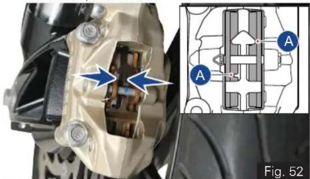
natural_image
Mechanical assembly diagram showing internal components and a close-up of a mechanical component (no text or symbols present)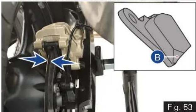
natural_image
Mechanical assembly diagram showing a bracket with blue arrows and a close-up of a mechanical component labeled B (no text or symbols present)TVS Racing
- If the wear is found beyond the wear indicator (A & B) groove as shown in the figure in any one of the pad, replace brake pads as a set with a new one. (ref. Fig. 52 & 53)

Warning
If the brake pads are used beyond this groove, leads to metal support contact with the brake disc and affects the braking efficiency, disc integrity and leads to unsafe riding conditions to the rider.

Caution
Replace the brake pads as a set, if the wear indicator shows beyond the wear limit.
Rims and Tubeless Tyres
Ensure the safety precautions listed in the page
129 are followed properly.
Rims
- Visually inspect the front and rear wheel rims for any defects. If found any, have the rims inspected at TVS Motor Company Authorised Main Dealer and get it replaced if necessary.
Tyre pressure
Check the tyre pressures atleast once in a week if not more frequently. Insufficient tyre pressure not only fasten tyre wear, but also seriously affects the stability of the vehicle and may lead to rim bend or damage.
- Under-inflated tyres make smooth cornering difficult and over-inflated tyres decreases the contact with the ground which can lead to skidding and loss of control.
- As the tyre pressure is affected by changes in the temperature and altitude, check and adjust the pressure more frequently whenever your vehicle is used on such conditions.
- Be sure that the tyre pressures are within the specified limit at all times.
| Solo / Pillion | |
| Front | 2.25 kg/cm ^2 (32 PSI) |
| Rear |

Warning
The tyre inflation pressure in cold condition is extremely important for the performance and the safety of the rider. Improper tyre pressure may result in: stability and handling issues, wobbling, hard steering, bumpy ride, uneven tyre wear etc.
When minor puncture occurs, tubeless tyres take a long time to deflate, as they tend to hold the air inside. If the tyres is found with low pressure, check the tyres for puncture.
Check and adjust the tyres pressure only when the tyres are cold.
Be sure to tighten the valve dust caps securely to prevent leaks while riding.
Ensue correct tyre pressure to avoide rim bend or damage.
TVS Racing
Tyre tread condition
Whenever the tyre pressure is checked, ensure to check the tyre treads and side walls for wear, damage and foreign objects.
The tyres also to be checked for:
- Bumps or bulges in the sides of the tyre or in the tread.
- Cuts, splits or cracks in the tyre (replace the tyre without fail if found any of the above issues to ensure the safety of the rider).
- Replace the tyre when the tyre wears off to the tyre wear indicator level (1) which is indicated by the tyre wear indicator (TWI) mark (2) on the side surface of the tyre (ref. Fig. 54).
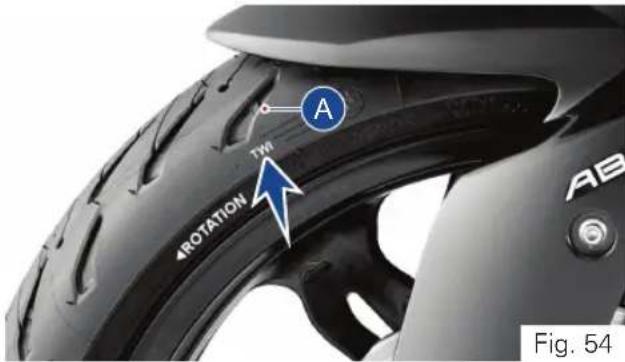
- Tread depth of the tyre should be minimum 2 mm if the vehicle speed is higher than 100 kmph, and it shall be minimum 1 mm if the vehicle speed is lesser than 100 kmph.
| Tread depth (min) : | 2 mm (> 100 kmph) |
| 1 mm (< 100 kmph) |

Warning
Visually inspect the tyres at regular intervals for cracks and cuts, especially on the side walls, and bulges or large stains that indicate internal damage. Replace them if damaged.
Remove any stones or other foreign bodies stuck in the tread.

Note
Tread wear marks are integrated into the main grooves on every tyre. If the tyre tread has worn down to the level of the marks, the tyre is completely worn. The location of the tread wear marks are indicated by an aero mark on the edge of the tyre (ref. Fig. 48). Replace the tyre when the minimum tread depth is reached.
TVS Racing
Tyre replacement
- The tyres fitted on your motorcycle were designed to match the performance capabilities of your motorcycle and provide the best combination of handling, braking durability and comfort. The recommended tyres for your motorcycle are:
| Front | 110/70-R17 M/C 54H Tubeless / 110/70 ZR17 M/C 54W Tubeless |
| Rear | 150/60-R17 M/C 66H Tubeless / 150/60 ZR17 M/C 66W Tubeless |
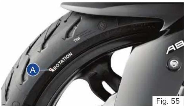
- While re-assembling the tyre, ensure that the arrow mark (1) provided on the side walls of the tyre faces the direction of wheel rotation (ref. Fig. 55).

Warning
Have the tyres replaced at only TVS Motor Company Authorised Main Dealer or Michelin Authorised Dealer. Proper removal and reassembly of wheels and the tyres are essential.
Use only the recommended tyre. Use of a tyre other than the standard will cause instability. Be sure the wheel is balanced after the new tyre is installed.

Caution
Side walls of the tubeless tyres which are in contact with the wheel rim are only seals the air inside the wheel assembly. Hence, care should be taken not to damage the side walls of the wheel rim during removal and reassembly of the tyres.

Note
Wheel balancing to be done every 1 year or every 10000 km. In addition, after every tyre puncture repair or replacement, wheel balancing to be done without fail. Do not remove or alter the position of wheel balancing weights after the completion of wheel balancing.
Tyre repair
- Do not repair the punctured tyre and it should be only replaced. If it is necessary to ride on a repaired tyre, never exceed the vehicle speed above 100 kmph until the tyre is replaced.

Warning
Do not repair the punctured tyre. It should not be replaced. If it is necessary to run the vehicle on a repaired tyre, never exceed 100 kmph speed until the tyre is replaced.
Never install a tube inside a tubeless tyre on this motorcycle. The tube may get burst during ride due to excessive heat buildup which will result in serious consequences.

Warning
Since the rims of this motorcycle is designed for tubeless tyres, use tubeless tyres only. During hard acceleration or braking, a tube tyre could slip on the rim and deflate rapidly.
Drive Chain
Ensure the safety precautions listed in the page 129 are followed properly.
The drive chain's service life is purely depended upon the proper lubrication and adjustment. Poor maintenance of drive chain can cause premature wear or damage to the drive chain and sprockets.
The drive chain must be inspected, cleaned, adjusted and lubricated as per the planned maintenance schedule. Under severe usage, or when the motorcycle is used more dusty or muddy areas, more frequent maintenance is necessary.
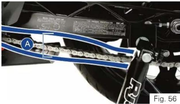
Slackness inspection
- Ensure the engine is turned OFF and the vehicle is in neutral.
- Place the motorcycle on its centre stand (if available) or side stand or in auxiliary stand (paddock stand ref. page 163).
- Using the fingers, check the slackness of the chain at the lower portion, midway (A) between the sprockets (ref. Fig. 56).
- The slackness (A) should be between 30 to 40 mm at the various points of the chain.
Drive chain slackness 30 to 40 mm
- The chain should be adjusted at the point of least deflection.
Adjustment
- Place the vehicle on centre stand (if applicable) or side stand or auxiliary stand (paddock stand) on a flat firm surface.
- Loosen the rear axle nut (1) using a proper spanner from the tool kit (ref. Fig. 51).
- Release the lock nuts (2 & 3) (ref. Fig. 51 & 52) using proper spanner from the tool kit (ref. page 162).
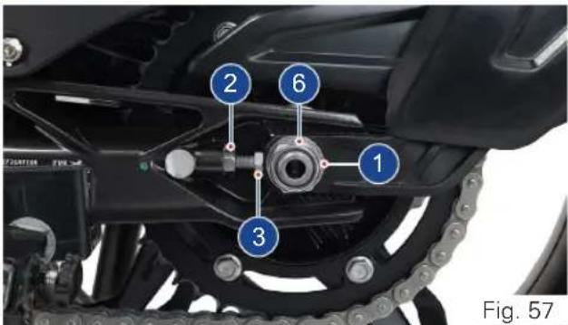
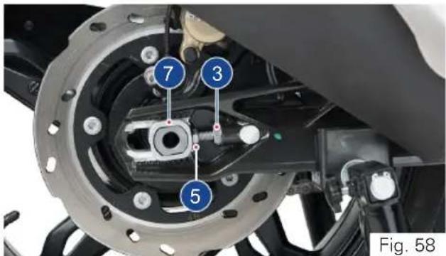
TVS Racing
- Turn the adjuster screws (4 & 5) 'in' or 'out' to obtain the specified slackness in the chain (ref. Fig. 57 & 58).
- While ensuring that the notch in the chain adjuster (6 & 7) is adjusted to the same scale value on both left and right sides, tighten the locknuts to the specified torque.
- Similarly, tighten the rear axle nut and lock nut to the specified torque, and check and ensure the chain slackness (ref. Fig. 57 & 58).
Axle nut tightening torque 100 ± 15 Nm Lock nut tightening torque 19 ± 3 Nm
Caution
Chain can be adjusted when vehicle is supported by centre stand (if applicable) or side stand or auxiliary stand (paddock stand) in no load condition.
Always have these tightening torques to be checked at TVS Motor Company Authorised Main Dealer after assembly for safety.
TVS Racing
Cleaning
- Slowly rotate the rear wheel in driving direction or wheel rotation direction and spray the recommended cleaning spray.
- Leave the cleaning solvent to soak for few minutes. Wipe off the solvent on the chain with a dry, clean cloth thoroughly. Use a soft brush if the chain is dirty.
Lubrication
- Ensure the chain is cleaned thoroughly and the solvent is wiped off completely.
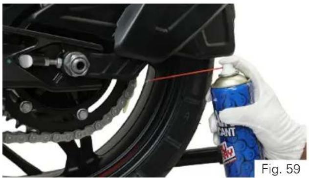
natural_image
Close-up of a hand holding a spray can on a black motorcycle tire, with chains and mechanical components visible (no text or symbols)- Slowly rotate the rear wheel in driving direction or wheel rotation direction. Apply recommended spray liberally as shown to the drive chain inner lower runs (ref. Fig. 59).
- Ensure both the row links are lubricated.

Warning
Avoid getting lubricant on the brakes or tyres. Avoid applying excess chain lubricant to prevent spray onto your clothes and the motorcycle.

Caution
The chain fitted on your motorcycle has X-Rings to protect the moving parts of chain from dirt, and to hold the lubricant inside. If the chain is cleaned using any solvent other than those specific for X-ring chains or washed using steam or water cleaners or a wire brush or an abrasive cleaner, the X-ring seals might be damaged irreparably.
Use only MOTUL C2 spray to lubricate the chain. Using non-specific lubricants may cause severe damage to the chain and the front and rear sprocket.
TVS Racing
Front Wheel
Ensure the safety precautions listed in the page 129 are followed properly.
Removal
- Carefully place the motorcycle in auxiliary stand (paddock stand ref. page 163).
- Loosen the left side clamping screws (1) and (2) (ref. Fig. 60).
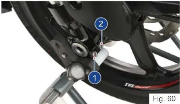
- Remove the locking screw (3) (ref. Fig. 61).
- Loosen the right side clamping screws (4) and (5).
- Slightly press the quick-release axle (6) inward for a better grip on the right side.
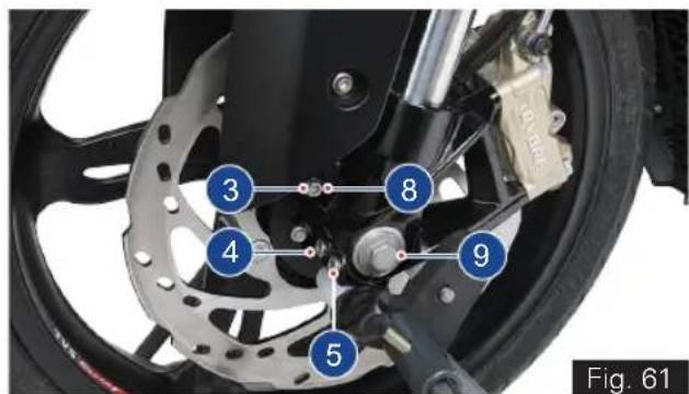
- Support the front wheel and slowly pull out the quick-release axle (6) from the left side (ref. Fig. 62).
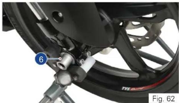
natural_image
Close-up of a motorcycle's wheel assembly with a numbered component (6) and no visible text or symbols on the main body.- Place the front wheel down and roll it forward out of front suspension. Ensure not to damage the wheel speed sensor during the removal process.
- Take out the spacer bush (7) from the left side of the wheel hub (ref. Fig. 63).
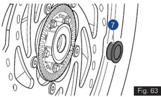
natural_image
Technical diagram of a mechanical assembly with labeled components (no readable text or symbols)
Caution
Ensure not to damage the brake caliper during wheel removal.
Do not actuate the brake lever after the wheel is removed. Unintentional press of brake lever leads to brake pads binding.

Note
During the wheel removal, take additional care to prevent the wheel rims from scratches.
Reassembly
- Push the brake pads of front caliper away from together to ease the front wheel entry in to front suspension.
- Loosen the mounting screw (8) and take out the speed sensor (9) from front suspension.
- Fix the spacer bush (7) on the left side of wheel hub (ref. Fig. 63).
- With the care, roll the front wheel into the front suspension so that there is no damage to the wheel speed sensor.
- Lift the front wheel. While ensuring the proper seating of brake disc into the caliper assembly, insert the quick release axle.
- Remove the front wheel stand and stroke the front fork several times without applying the brake.
- Mount the front wheel stand again and install the locking screw (3) with specified torque (ref. Fig. 61).
Tightening torque 50 ± 7 Nm
• Install the clamping screws (1,2,4 & 5) and tighten to the specified torque (ref. Fig. 54 & 55).
Tightening torque 19 Nm
- Assemble the speed sensor (9) and mounting screw (8) in front suspension.

Caution
Always have these tightening torques to be checked at TVS Motor Company Authorised Main Dealer after assembly for safety.
TVS Racing
Rear Wheel
Ensure the safety precautions listed in the page 129 are followed properly.
Removal
- Carefully place the motorcycle in auxiliary stand (paddock stand ref. page 163) or centre stand (if available).
- Place a support below the rear wheel to avoid falling of wheel after removing the quick release axle.
- Remove the mounting screw (1) from the speed sensor mounting and carefully take out the speed sensor (2). (ref. Fig.64)
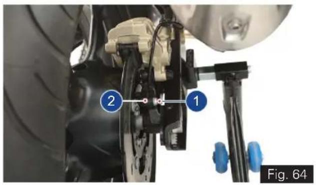
- Remove the axle mounting nut (3, ref. Fig 65) using the proper tool from the tool kit (ref. page 162).
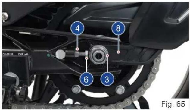
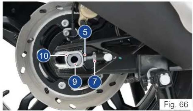
TVS Racing
- Release the lock nuts (4 & 5) and screw-in the adjuster bolts (6 & 7) (ref. Fig. 65 & 66).
- Remove the chain tensioner with hugger (8) and push the quick-release axle to the right as much as possible (ref. Fig 66).
- Carefully pull out the quick release axle (9) from the left side and take out the chain tensioner (10) (ref. Fig. 66).
- Roll the rear wheel forward as far as possible and disengage the chain (11) from the sprocket (ref. Fig. 67).
- Care should be taken not to damage the wheel speed sensor during this process.
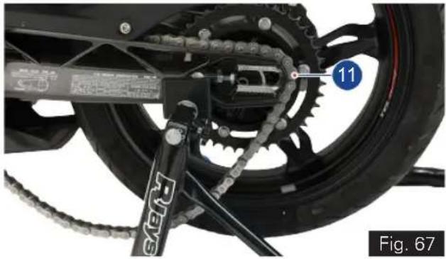
natural_image
Mechanical assembly diagram showing a bicycle wheel with gear and chains, labeled with number 11 (no readable text or symbols beyond label)- Carefully roll the rear wheel out from the swing arm while pulling the brake-caliper assembly back far enough to allow the rear wheel to come out.

Caution
Care should be taken not to damage speed sensor during its removal and reassembly. Ensure that the speed sensor is free from any mud / clogging with dirt.
Ensure not to damage the brake caliper during wheel removal.
Do not actuate the brake pedal after the wheel is removed. Unintentional press of brake pedal leads to brake pads binding.

Note
Sprocket assembly, spacer axle rear LH & RH are loose fits in the wheel. Make sure that no parts are damaged or mislaid during removal and reassembly of the wheel.
During wheel removal, take additional care to prevent the wheel rims from scratches.
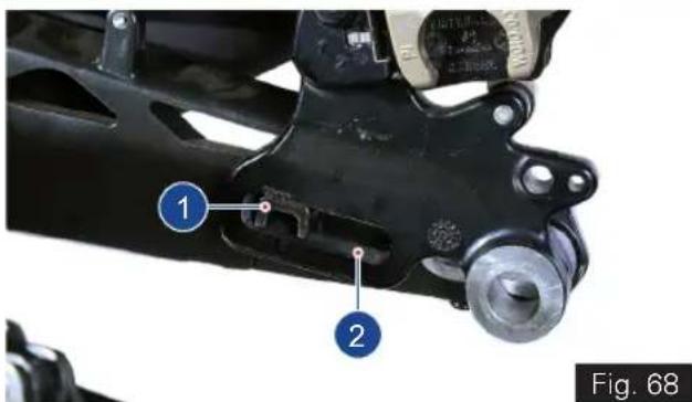
Reassembly
- Carefully roll the rear wheel on the support into the swing arm, along with LH & RH spacers and sprocket, as far as necessary to allow the brake-caliper to be inserted while taking care of wheel speed sensor.
- Push the brake pads away from together to ease the rear wheel entry into swing arm.
- Place the brake-caliper (1) on the guide (2) of the swing arm as shown (ref. Fig. 68)
- Roll the rear wheel further into the swing arm, while pushing the brake-caliper assembly forward at the same time.
TVS Racing
- Roll the rear wheel as far forward as possible and loop the chain over the sprocket.
- Insert the quick-release axle along with the chain tensioner from left side of the swing arm while ensuring that the axle is seated properly into all the components.
- Assemble the left side chain tensioner.
- Assemble the axle nut along with the washer and hand tighten it.
- Adjust the chain slackness and tighten the lock nuts, and the axle nut to the specified torque (ref. page 185).
• After tightening the axle nut, once again check and confirm the chain slackness. - Assemble the speed sensor (2) and mounting screw (1) in rear caliper (ref. Fig. 58).

Caution
Chain can be adjusted when vehicle is supported by centre stand (if applicable) or side stand or auxiliary stand (paddock stand) in no load condition.
Always have these tightening torques to be checked at TVS Motor Company Authorised Main Dealer after assembly for safety.
Battery
Ensure the safety precautions listed in the page 129 are followed properly.
Since the maintenance free battery is used in your motorcycle, it is not necessary to check the battery electrolyte level or add distilled water.
If your battery seems weak ie. if you are facing starting issues or other electrical issues, contact TVS Motor Company Authorised Main Dealer.
Removal
- Turn OFF the ignition.
- Remove the pillion and rider seats as explained in page no. 99 to access battery.
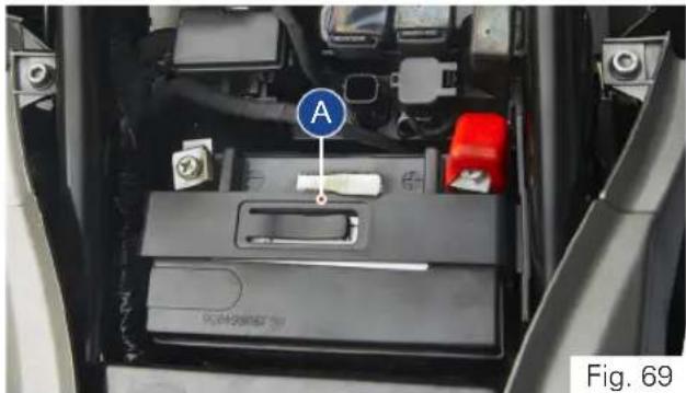
natural_image
Interior view of a car battery pack with labeled component A (no text or symbols beyond label)- Remove the mounting bolt and take the battery holder (A) (ref. Fig. 69)
- Disconnect the negative terminal (1) first followed by the positive terminal (2) (ref. Fig. 70). Carefully take out the battery.
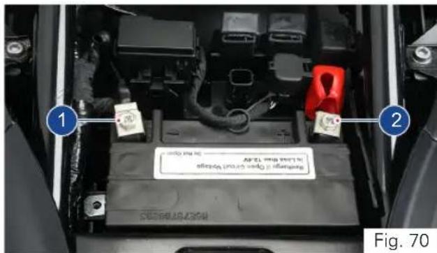
Re-fitment
- Reinstall the battery in the reverse order of removal.
- Connect the positive terminal first and then the negative firmly to avoid any damages to electrical system / battery. Make sure the rubber boot is intact with positive terminal.
TVS Racing

Warning
Battery develop explosive gases. Keep it away from heat sources. If charging is required, the battery must charged in well ventilated area.
Unusable battery must be disposed in environment friendly manner. Do not discard it with household trash. Handover the battery to the battery Dealers or to a recycling centre that accepts used batteries.

Caution
Never operate the motorcycle with discharged battery as it may damage electrical components.
Do not push start the vehicle, use a good battery or jump cable to start the vehicle incase of battery drain.

Note
If the motorcycle is to remain unused for a long time (a month or longer), it is advisable to disconnect the battery terminals or have the battery removed by a skilled personnel.
TVS Racing
Fuses
The electrical components of your motorcycle are protected by six fuses housed inside a fuse box and located below the rider seat.
To access the fuses, park the motorcycle on a flat and firm surface and remove the pillion and rider seats as explained in page no. 99.
A 'fuse puller' (A) is placed on the battery holder can be used to pull out the fuse from the fuse box during replacement.
Removal and replacement
- Turn OFF the ignition.
- Press the lock and open the fuse box cover (1) (ref. Fig. 71).
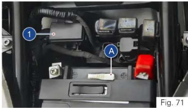
- Pull out the defective fuse and re-fix the new one with same rating.
- Close the fuse box cover and ensure the proper locking.
You can identify a blown fuse by the interrupted centre link (1) (ref. Fig. 72).
1
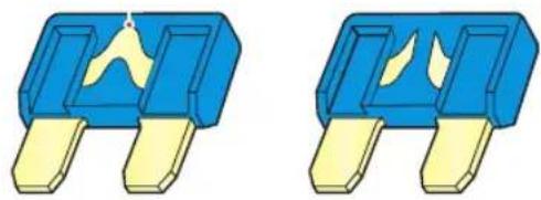
natural_image
Two identical blue and yellow electronic component blocks with internal yellow traces (no text or symbols)GOOD FUSE BLOWN FUSE
Fig. 72
Fuse assignments
- Each fuse inside the fuse box are assigned for different electrical load and it is listed the table given below. Never change the fuse rating to protect your electrical system and to avoid severe damages.
| Fuse Colour Electrical load | |
| F1 - 7.5A | Brown Lambda / starter relay / purge / SAS / relay fuel pump module / injector / relay EFI / ignition coil |
| F2 - 7.5A | Brown Speedometer / diagnostic / HECU / ECU / cooling fan |
| F3 - 30A | Green Main fuse |
| F4 - 25A | Cream HECU |
| F5 - 10A | Red All lights / horn LH & RH |
| F6 - 10A | Red EFI / speedometer |
| 10A | Red HECU |
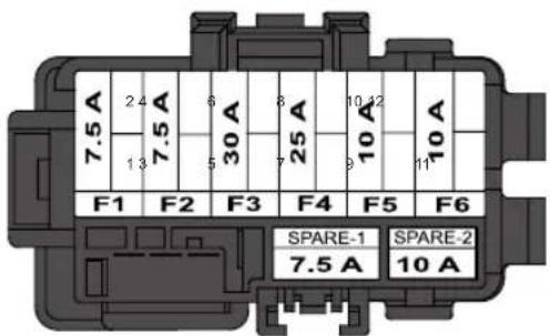
FUSE BOX
Fig. 73
Fuse arrangement
- Fuses are arranged inside fuse box as given in the figure (Fig. 73). Ensure to fix the right rating fuse at right location.

Caution
Do not use the motorcycle by shorting the wires without a fuse. Never use a fuse with a rating other than that specified. Failure to observe above rules may damage the electric system or even cause fire.

Note
A sticker with fuse colour codes and rating is pasted inside the fuse box cover which can be referred during fuse replacement.
Ensure to replace the 'fuse puller' in the same place for future usage.
Care should be taken not to spray water on electrical components.
Fuse location
- Spare fuse for the each of the fuse is located inside the fuse box (A) and as well as in the wiring harness (B) below the seat latch of pillion seat (ref. Fig. 74).
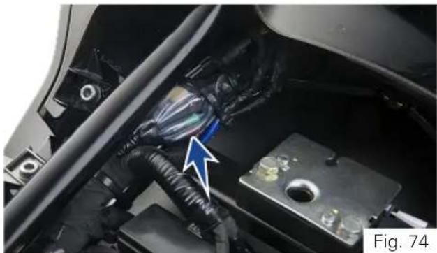
natural_image
Close-up of a car's engine compartment showing wiring and battery, with a blue arrow pointing to a component (no visible text or symbols)TVS Racing
Mirror Assembly
Ensure the safety precautions listed in the page 129 are followed properly.
Assembly
- Remove the allen screw (2 nos) from the bracket licence complete using a hexagonal key 5 mm from the tool kit (ref. page 162) (ref. Fig. 75).
- Assemble the mirror assembly LH to the bracket licence complete along with grommets (2 nos) on both sides bracket licence complete.
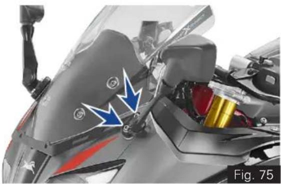
natural_image
Close-up of a motorcycle's front wheel and side-mounted sensor assembly (no visible text or symbols)- Now tighten the allen screw (2 nos) with the bracket licence complete using a hexagonal key 5 mm from the tool kit (ref. Fig. 76).
Tightening torque 7 ± 1 Nm
• Similarly assemble the mirror assembly RH.
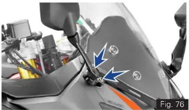
natural_image
Close-up of a motorcycle's side mirror and steering wheel, showing blue arrows indicating motion or force direction (no text or symbols)Diagnostic Connector
The diagnostic connector is located below the rider seat. Follow the procedure given below to access the connector.
Removal
- Park the motorcycle on a flat and firm surface and remove the pillion and rider seats as explained in page no. 162.
- Turn OFF the ignition.
• Gently pull out connector along with its cap from its location by releasing the lock (1) (ref. Fig. 77). - Release the lock of the cap and take out the cap carefully.
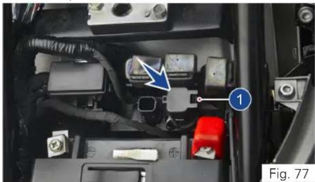
natural_image
Interior view of a car's battery pack with labeled components (no readable text or symbols)Re-fixing
- Re-fix the cap of the connector and ensure the proper locking.
- Re-fix the connector to its location and lock it properly.

Caution
Diagnostic connector to be accessed and used by the trained personals of TVS Motor Company Authorised Main Dealer or by the other authorised persons of TVS Motor Company Limited during service. Do not fiddle with system at unauthorised service location.
Ensure to re-fix the diagnostic coupler cap after the usage to avoid damages to the electric system due to water entry. Secure the connector in it's location without fail to avoid getting damaged.
TVS Racing
Cleaning your Motorcycle
For maintaining the original shine on metal parts surface and painted parts surface, wash and clean your motorcycle at regular intervals depending on usage and particular road conditions.
- Use only specific products. Avoid aggressive detergents and solvents.
- Use only water and natural soap to clean glass and the seat.
- To prevent stains, do not wash the vehicle immediately after it has been exposed to strong sunlight and do not wash it in the sun.
- If the parts of the engine are unusually dirty or greasy, use a de-greasing agent while taking care of transmission components (like chain, front and rear sprockets, etc.).

Caution
Never clean the motorcycle using hot or high pressure water jets. Cleaning the motorcycle with high pressure water jet may lead to serious problems in front fork, wheel assemblies, brakes, electrical systems, inlet and exhaust systems which will result in reduced safety.
- Transmission components can be rinsed with warm water and dried with clean dry cloth.
- Clean the radiator regularly. Use a hose with low water pressure to clean the radiator fins blockage. This prevents the engine from overheating due to insufficient cooling. Care should be taken not to damage the radiator fins during cleaning.

Warning
There may be a loss of braking efficiency immediately after washing the motorcycle. Greasing or lubricating the brake discs leads of loss of braking. Oil-free solvent to be used for cleaning the brake discs.
The head lamp may be get fogged up after washing, rain or moisture. Switch ON the head lamp for a short period of time to dry any condensation.
Maintain minimum distance of 60cm between the water jet nozzle and the vehicle. Do not direct the jet onto electrical component and connectors.
Storage Procedures
For storing your motorcycle for longer periods of over a month and above, we recommend to carry out the following steps:
- Clean the motorcycle. Park the vehicle on centre stand (if applicable) or in auxiliary stand (refer page 163).
• Warm-up the engine and drain the engine oil.
• Empty the fuel tank. - Remove the spark plug and feed in several drop of engine oil through the spark plug hole. Crank the engine few times and reinstall the spark plug.
- Disconnect and remove the battery. Store it away from direct sunlight and freezing temperatures. Place a suitable support at the bottom of the frame so that both the tyres are off the ground. This will ensure the better tyre life.
- Protect the vehicle with the suitable cover and store the vehicle inside a garage or similar area to avoid damage due to dust and rain.
- Make sure that the storage area is well ventilated and free from any source of flame or spark.

Caution
Do not park the vehicle on a slope or soft ground or else it may fall.
During storage the battery must be checked and if required recharged at least once in a month.
Restoring the Motorcycle to use
- Take the motorcycle out of garage and clean the motorcycle thoroughly (ref. page 158).
- Remount the battery after bench charging if required.
- Fill the engine oil and check the oil level using the gauge.
- Lubricate the necessary parts.
- Fill up fresh fuel in the fuel tank (ref. page 95).
- Check and inflate the tyre pressure to the specified limit.
- Check and correct the points mentioned in pre-ride check (ref. page 102).

Note
Turn on the ignition and start the engine. Allow the to run in idle mode for few minutes and ride out.
Taking Long Trips
When taking the motorcycle a long trip more than 500 km follow the instructions given below:
A) Keep the following items for use in case of emergency
- Complete tool kit and first aid kit.
- Recommended spark plug one number.
- Clutch cable each one.
B) Precautions to be taken for the journey:
- Ensure engine oil and brake fluid level are upto the mark.
- Ensure the coolant level.
- Adequate fuel in the tank.
C) Check the motorcycle for the following:
- Tightness of all fasteners for the correct torque value.
• Fitness of tyres and tyre pressure.
• Working of all the lamps and horn.
- Balancing of wheel.
- Smooth functioning of all cable and their free plays.
- Smoothness of steering operation.
- Slackness and lubrication of chain.
- Front and rear brake functioning and rear brake switch working.
- Front fork for any abnormality.
- Spark plug cleanliness and condition.
• Air filter element cleanliness. - Lubrication of all necessary parts.
- Any other jobs as necessary.

Caution
Long journey are to be taken only after the running-in (ref. page 01).
Have your vehicle checked for the above mentioned items at TVS Motor Company Authorised Main Dealer.

Note
Ensure the first aid equipments are changed periodically based on the expiry.
GENERAL INFORMATION
TVS Racing
Tool Kit
To assist you in performing certain aspects of periodic maintenance and emergency repairs, a tool kit is supplied along with the vehicle.
- The tool kit (A, ref. Fig. 78) is located below the pillion seat (ref. page 99 for seat removal procedure).
-
The tool kit consists of one number each of the following:
-
Tool bag
- Double ended open jaw spanner 12x13
- Double ended open jaw spanner 10x16
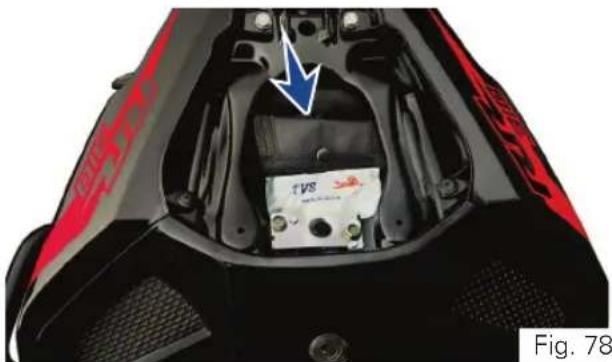
natural_image
Close-up of a black and red sports motorcycle seat with an internal battery pack and blue arrow indicating direction (no text or symbols)- Bit +/-
- Grip driver
- Adjuster shock absorber rear
- Handle ring spanner
- Hexagonal key 5 mm
- Ring spanner
Note
It is recommended to use the tool kit incase of any emergency only. It is always advisable to take your vehicle to TVS Motor Company Authorised Main Dealer.

natural_image
Abstract blue and white geometric pattern with diagonal stripes (no text or symbols)TVS Racing
Auxiliary Stand (Paddock Stand)
Front wheel stand (ref. Fig. 79, 80 & 81)
Place the motorcycle on its centre stand (if applicable) or on rear wheel stand (ref. page 165) on a flat firm surface.
Use the auxiliary stand supplied for lifting the front wheel (the stand is an accessory and it is available with the TVS Motor Company Authorised Main Dealer).
- Loosen the clamping screws (1) of the stand adopters.
- Move away the adopters (2 & 3) in such way that the front forks fit between them.
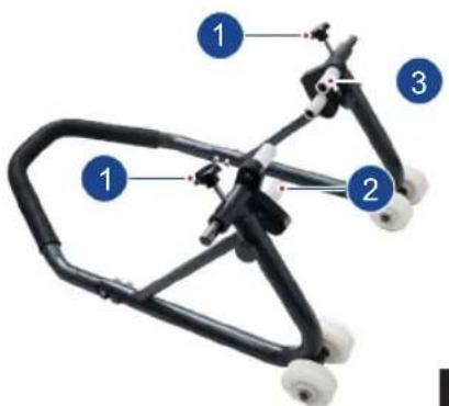
- Centre the stand relative to the front wheel and push it against the front axle.
- Align the two adapters (2a & 3a) so that the front forks are securely seated.
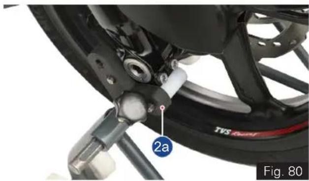
natural_image
Close-up of a motorcycle wheel assembly with visible components and a numbered label (2a), no readable text or symbols beyond the label.Fig. 79
TVS Racing
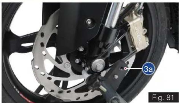
natural_image
Close-up of a motorcycle wheel with visible brake calipers and a labeled component (3a), no readable text or symbols beyond the label.- Apply uniform pressure to push the stand down and raise the motorcycle. (ref. Fig. 76)
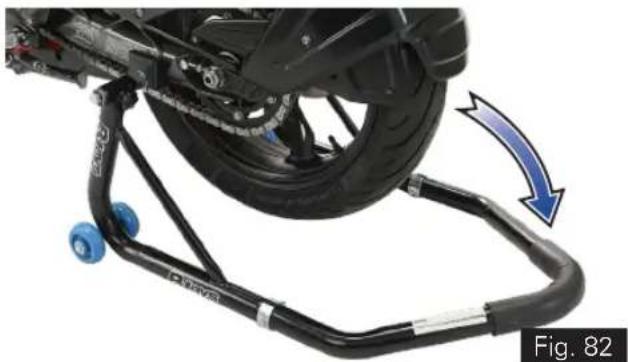
natural_image
Mechanical assembly with blue wheels and a blue arrow indicating motion, labeled Fig. 82 (no text or symbols on the diagram itself)- Tighten the clamping screws (1).

Caution
Centre stand (if available in the vehicle and parked using it) retracts if the motorcycle is lifted too high.
When raising the motorcycle, make sure that the centre stand (if available in the vehicle and parked using it) remains on the ground. Else the motorcycle is supported by the rear wheel stand to avoid falling of the motorcycle.
TVS Racing
Rear wheel stand
Use the rear wheel stand (the rear wheel stand is an accessory and it is available with the TVS Motor Company Authorised Main Dealer).
- Ensure that the motorcycle is parked on a flat and firm surface.
- Loosen the clamping screws (1) of the stand adopters.
- Move away the adopters (2 & 3) in such way that the swing arm fits between them (ref. Fig. 83).
- Ensure that the axle is not covered.
• Position the stand (ref. Fig. 84).
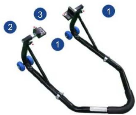
Fig. 83
- Make sure that the vehicle is secured so that it cannot topple sideways.
- Push the stand down until the motorcycle is standing upright and the handle of auxiliary stand is resting on the floor properly.
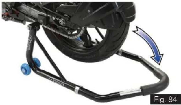
natural_image
Mechanical assembly with blue wheels and a blue arrow indicating motion, labeled Fig. 84 (no text or symbols on the diagram itself)
Caution
When raising the motorcycle, make sure that the vehicle is secured so that it cannot topple sideways.
TVS Motor Company Limited ('the Company') gives this warranty with respect to the TVS Apache RR 310 manufactured by the Company.
While the Company has taken every care to maintain quality in the manufacture of the TVS Apache RR 310, the above said warranty is subject to other terms of warranty:
- Standard Warranty - During 24 months from the date of purchase or during the first 30,000 km of run*
• Additional Warranty - During 36 months from the completion of standard warranty or during the first 50,000
km of run**.
The vehicle in the hands of original retail purchaser, whichever is earlier, the parts of the vehicle covered under warranty which prove to the satisfaction of the Company to have a manufacturing defect will be repaired or replaced free of cost.
The Company's obligation under this warranty is limited to repairing or replacing, free of cost, those parts of the vehicle which upon examination by the Company may prove to the Company's satisfaction to have a manufacturing defect, and in such cases the Company's decision either to repair or replace the affected parts will be final. In the event of replacement of parts, the Company also reserves the right to use parts of the same brand as the affected parts or any other brand which is used by the Company in the course of manufacture. All parts replaced under this warranty will become the property of the Company and must be returned to the company.
Limitations of Warranty:
This warranty shall not apply to following condition:
- Any natural wear and tear, including without limitation, aging.
- Warranty claims on proprietary items such as tyres and batteries etc., should be referred by the user directly on the respective manufacturer, as per their warranty terms and the Company shall not be liable in any manner in respect to the same.
- Battery warranty for "MF type (Maintenance Free)" is applicable for a period of 21 months from the date of charging or 18 months from the date of sale or 20,000 kms, whichever is earlier.
- Battery warranty for "Lead Acid type" is applicable for a period of 15 months from date of charging or 12 months from date of sale or 10000 kms whichever is earlier.
- Parts repaired or replaced under this warranty are warranted only throughout the remainder of the original warranty period.
- The Company is not liable for any delay in servicing due to reasons beyond the control of the Company or any of its Authorised Main Dealers.
- In any event, the Company is not liable for indirect, remote, incidental or consequential damages.
- The Company may make any modification or improvement to vehicles in future production at any time without prior notice and without any obligation to install the same on vehicles previously dispatched for sale.
- Any claim under this warranty will lie only when the customer:
- takes his vehicle to an Authorised Main Dealer of the Company and reports the problem he / she felt in the vehicle to enable the Authorised Main Dealer to inspect the same and assess the cause for the reported problems.
- This is the only warranty given by the Company for the TVS Apache RR 310. No employee, Dealer or other person is authorised to extend or enlarge this warranty.

Warning
Modifications to this vehicle not approved by the TVS Motor Company may cause loss of performance and render it unsafe for use and disqualifies for warranty coverage also.

Note
This warranty is applicable only for the vehicles availing warranty service (periodic service) when it falls due at TVS Motor Company Authorised Main Dealer only.
Following Toll Free numbers can be contacted for battery related queries if any:
Incase of EXIDE battery, call :- 1800 103 5454 Incase of AMCO battery, call :- 1800 425 0096
Incase of TATA GREEN battery, call :- 1800 419 8888 Incase of AMARON battery, call :- 1800 425 5858

Standard Warranty (24 months or first 30,000 km) - List of parts not covered under warranty*
| ITEM WHAT TO CHECK FOR | |
| Eninge | - |
| Normal Maintenance Operations | Engine tune-up, decarbonizing, fuel system cleaning, oil and coolant changes, head light focusing, fastener re-tightening, tuning of EFI system, clutch, brakes, greasing of steering system and pivot pins as well as other normal adjustments. |
| Wear and Tear Items | Chain, sprockets, clutch and brake linings, fasteners, shims, washers, oil seals, gaskets etc. |
| Electrical | Fuse, LEDs are only in head lamp, tail lamp, tsl |
| Service Maintenance Parts | Oil filter, spark plug, air filter, oil, coolant, clamps |
| Rubber, Rexine and Plastic Items | All hoses , pipes and plastic aesthetics |
| Proprietary Items | Battery and tyres (the warranty terms are subject to our agreement with proprietary OEM)(Battery warranty for “MF type (Maintenance Free)” is applicable for a period of 21 months from the date of charging or 18 months from the date of sale or 20,000 kms, whichever is earlier).(Battery warranty for “Lead Acid type” is applicable for a period of 15 months from date of charging or 12 months from date of sale or 10000 kms whichever is earlier). |
| Others Factors | Parts of the vehicle getting affected due to atmospheric effect / environmental factors (rusting, paint peel off etc.). However, depending on the vehicle usage condition, warranty would be accepted up to 2 years from the date of purchase. |
Standard Warranty (24 months or first 30,000 km) - List of parts not covered under warranty*
| ITEM WHAT TO CHECK FOR | |
| Others Factors | Parts of the vehicle which have been tampered with, altered, repaired or replaced by persons not authorised by the Company and which in the sole judgement of the Company affect the performance of the vehicle. |
| Parts which are used in conjunction with parts not made or recommended by the Company. | |
| Parts suffering damage or resultant damage by accident, misuse, negligent treatment, use of bad quality lubricants or coolant or impure fuel or by omission to follow the guidance and instructions contained in this owner's manual. | |
| Vehicles on which engine number or chassis number is deleted, defaced or altered. Vehicles on which any warranty service including scheduled pay service is not availed when it falls due (at TVS Motor Company Authorised Main Dealer). | |
| Vehicles sold or transferred by original retail purchaser. Vehicles used for racing or any competition or used otherwise than for ordinary personal transportation. Vehicles which have been taken out of India. Vehicles affected by natural calamities like flood, earthquake, tsunami, storm etc,. | |
| If the vehicle has been used for commercial purpose like taxi or used for rental or hiring or any other purpose other than regular personal transportation. |
Additional Warranty (36 months or first 50,000 km) - List of parts not covered under warranty**
| ITEM WHAT TO CHECK FOR | |
| Engine | Guide cam chain, tensioner cam chain, cam chain, valves (for carbon deposition alone), finger follower and Stem oil seal |
| Normal Maintenance Operations | Engine tune-up, decarbonizing, fuel system cleaning, oil and coolant changes, head light focusing, fastener re-tightening, tuning of EFI system, clutch, brakes, silencer (aesthetic failures), suspensions (leakage failures), greasing of steering system and pivot pins as well as other normal adjustments |
| Wear and Tear Items | Chain, sprockets, clutch and brake linings, control cables fasteners, shims, washers, oil seals, gaskets etc. |
| Electrical | Fuse, headlamp, tail lamp, TSL, control switches, instrument cluster, wheel speed sensor, ignition coil, injector, relays and horn. |
| Service Maintenance Parts Oil filter | Spark plug, air filter, oil, coolant, clamps |
| Rubber, Rexine and Plastic Items | All hoses , pipes and plastic aesthetics |
| Proprietary Items | Battery and tyres (the warranty terms are subject to our agreement with proprietary OEM)(Battery warranty for “MF type (Maintenance Free)” is applicable for a period of 21 months from the date of charging or 18 months from the date of sale or 20,000 kms, whichever is earlier).(Battery warranty for “Lead Acid type” is applicable for a period of 15 months from date of charging or 12 months from date of sale or 10000 kms whichever is earlier). |
Additional Warranty (36 months or first 50,000 km) - List of parts not covered under warranty**
| ITEM WHAT TO CHECK FOR | |
| Others Factors | Parts of the vehicle getting affected due to atmospheric effect / environmental factors (rusting, paint peel off etc.). However, depending on the vehicle usage condition, warranty would be accepted up to 2 years from the date of purchase. |
| Parts of the vehicle which have been tampered with, altered, repaired or replaced by persons not authorised by the Company and which in the sole judgement of the Company affect the performance of the vehicle. | |
| Parts which are used in conjunction with parts not made or recommended by the Company. | |
| Parts suffering damage or resultant damage by accident, misuse, negligent treatment, use of bad quality lubricants or coolant or impure fuel or by omission to follow the guidance and instructions contained in this owner's manual. | |
| Vehicles on which engine number or chassis number is deleted, defaced or altered. Vehicles on which any warranty service including scheduled pay service is not availed when it falls due (at TVS Motor Company Authorised Main Dealer). | |
| Vehicles sold or transferred by original retail purchaser. Vehicles used for racing or any competition or used otherwise than for ordinary personal transportation. Vehicles which have been taken out of India. Vehicles affected by natural calamities like flood, earthquake, tsunami, storm etc.. | |
| If the vehicle has been used for commercial purpose like taxi or used for rental or hiring or any other purpose other than regular personal transportation. |
Service Information
There are five services planned for your TVS Apache RR 310 during the warranty period. Of these, first three are free services for which labour charges are free. In addition to these three free services, we have a scheme of two pay services. For keeping maintenance track of your vehicle, a service record sheet is also attached. Please have the record sheet filled by the Dealer who is carrying out the maintenance service.
Before you avail your first free service, please enter the particulars of your vehicle on the left side of this page. This will be useful for any reference.
For availing any of the warranty services, please take your vehicle and your owner's manual to any of our Authorised Main Dealer. After completing the warranty service, for your record, the Authorised Main Dealer will affix their stamp on last column of record sheet.
Periodic maintenance always helps good performance of an automobile and our services are planned to keep your TVS Apache RR 310 performing good.
Please note that carrying out the services for your vehicle at scheduled intervals is necessary for availing warranty.
And please also remember that, after the services are over, periodic servicing of your vehicle at appropriate intervals, depending upon its extent of use, will keep your vehicle at its best level of performance.
In case need any clarification or assistance, please feel free to write to us mentioning the frame number, engine number and the date of purchase of your vehicle also the name and place of the Authorised Main Dealer from whom you bought the vehicle and getting it serviced.
Service Department
TVS MOTOR COMPANY LIMITED
P.O.Box No. 4, Harita, Hosur - 635109,
TAMILNADU, INDIA.
Toll free no. :- 1800-258-7111
Pre-Delivery Inspection
Sl. No. Description
1 Inspect the vehicle for any visible damages / scratches
2 Inspect the battery charge and terminals connections
3 Ensure first aid kit and tool kit placed in the vehicle
4 Install left and right side mirrors
5 Inspect drive chain slackness and adjust if required
6 Inspect front and rear tyre pressure and inflate to specification if required.
7 Fill the fuel in the vehicle
8 Inspect the startability of the vehicle
9 Inspect and ascertain the working of all lamps and horn
10 Inspect head lamp focus and adjust if required
11 Conduct engine start suppression test
12 Test drive vehicle and ensure proper working of all controls and system
13 Clean the vehicle thoroughly
14 Using diagnostic tool, ensure there is no error codes
15 Code the service interval (distance and time) using diagnostic tool
16 Change the menu in cluster to odometer menu before handing over the vehicle to the customer
17 Explain of the product features and operations to the customer
18 Inspect the rear brake pedal free play and adjust if required
19 Check the front wheel and rear wheel freeness
20 Ensure any additional points communicated by TVS Motor Company Limited during the course

Planned Service Schedule (kms or month whichever of the two occurs early)*
| SI.No. Service Type Kms Months | ||||
| 1 1st Service Free 1000 2 | ||||
| 2 2nd Service Free 5000 6 | ||||
| 3 | 3rd Service | Free | 10000 | 12 |
| 4 | 4th Service | Pay | 15000 | 18 |
| 5 | 5th Service | Pay | 20000 | 24 |
| 6 | 6th Service | Pay | 25000 | 30 |
| 7 | 7th Service | Pay | 30000 | 36 |
| 8 | 8th Service | Pay | 35000 | 42 |
| 9 | 9th Service | Pay | 40000 | 48 |
| 10 | 10th Service | Pay | 45000 | 54 |
| 11 | 11th Service | Pay | 50000 | 60 |

Note
Free service entitles the customer to avail service as detailed in service instructions at free of labour charge. Cost of oil, coolant, brake fluid and other materials for the free service is chargeable. Charge for the pay services, cost of oil, coolant, brake fluid and other materials for the pay service should be borne by the customer.
* Please remember that, after the above schedule, periodic servicing of your vehicle at appropriate intervals, depending upon its extent of use, will keep your vehicle at its best level of performance.

BusyLife? EasyServicing!
Now, service your bike anywhere, anytime.
★ Service the vehicle at your door step.
★ Available for regular maintenance or breakdown service only.
★ Offered at nominal convenience charges.
Contact your nearest Dealership for details. ^†
^ Facility available at selected Dealerships only. Terms and conditions apply
TECHNICAL SPECIFICATIONS
TVS Racing
Recommended Fuel and Lubricants
| Fuel | |
| Recommended fuel grade BSVI ES Gasoline (containing upto 20% of ethanol by volume) | |
| Fuel capacity (usable) 11 ± 0.5 ltr | |
| Minimum required quantity of fuel 2 ltr | |
| Engine Oil | |
| Recommended manufacturer TVS / MOTUL | |
| Recommended grade TVSM TRU4 SAE 15W50 Synthetic oil / MOTUL 15W50 3000 4T Plus MA2 oil | |
| Recommended quantity 1700 ml (fresh assembly / full drain along with filter change) | |
| Coolant | |
| Recommended manufacturer Glysantine | |
| Recommended grade G48 | |
| Recommended quantity 1 litre (coolant and distilled water ratio 50:50) | |
| Cone set grease | |
| Recommended manufacturer As recommended by TVS Motor Company | |
| Recommended grade BEM 34-132 | |
| Recommended quantity 15 gm (in sachet) | |
Recommended Fuel and Lubricants
| Front fork oil | |
| Recommended manufacturer Kayaba | |
| Recommended grade KHL 15-10 | |
| Recommended quantity 440 ml / leg | |
| Chain cleaner | |
| Recommended manufacturer MOTUL | |
| Recommended grade C1 | |
| Cone set grease | |
| Recommended manufacturer MOTUL | |
| Recommended grade C2 | |
| Brake Fluid | |
| Recommended manufacturer BASF HYDRAULAN 404 / EQUIVALENT | |
| Recommended grade DOT 4 | |
Engine
| Bore 80 mm | |
| Stroke 62.1 mm | |
| Displacement 312.12 | |
| Compression ratio 10.94 : 1 | |
| No. of valves 4 | |
| Maximum power (Urban and Rain mode)(Sport and Track mode) | 19 kW @ 7700 rpm25 kW @ 9700 rpm |
| Maximum torque (Urban and Rain mode)(Sport and Track mode) | 25 Nm @ 6700 rpm27.3 Nm @ 7700 rpm |
| Engine idling rpm 1700 ± 200 rpm | |
| Idling CO% CO < 0.5% | |
| Idling HC ppm HC < 500 ppm | |
| Camshaft Double over head camshaft | |
| Fuel feed Closed loop EFI system | |
| Cooling system Liquid cooling | |
| Air filter Dry paper type |
Engine
| Oil filter | Wire mesh and Micronic paper filter |
| Lubrication system | Wet sump lubrication |
| Starting system | Electric starter |
Transmission
| Clutch system Wet multi plate type | |
| Gear shift pattern One down five up | |
| Number of gears Six speed, toe shift | |
| Primary transmission Spur gears | |
| Secondary transmission Chain and sprockets | |
| First gear ratio 3.000 | |
| Second gear ratio 2.06 | |
| Third gear ratio 1.59 | |
| Fourth gear ratio 1.29 | |
| Fifth gear ratio 1.10 | |
| Sixth gear ratio 0.95 | |
| Primary reduction 3.083 | |
| Secondary reduction 2.471 |
Dimension
| Overall length 2001 ± 20 mm | |
| Overall width 786 ± 5 mm / 793 mm | |
| Overall height 1135 ± 10 mm | |
| Saddle height 811 ± 10 mm | |
| Ground clearance 180 ± 5 mm | |
| Wheel base 1365 ± 12 mm | |
| Kerb weight 174 kg | |
| Pay load 130 kg | |
| Gross vehicle weight 304 kg |
Frame and Suspension
| Frame type Trellis type frame | |
| Front suspension USD fork 41 mm diameter | |
| Rear suspension Solid Die cast Aluminium swing arm directly hinged monoshox, pre-load adjustable. | |
| Fork stroke length 140 mm | |
| Rear suspension travel 119 mm | |
| First gear ratio 3.000 | |
| Steering angle 34^ ± 2^ | |
| Caster angle 25^ ± 1^ | |
| Turning radius 2542 ± 145 mm | |
| Gradability ≥ 10^ | |
| Banking angle 49^ ± 1^ | |
Wheels and Brakes
| Brakes | |
| Brakes type Disc brake with ABS | |
| Front brake size Hand operated 300 mm disc | |
| Rear brake size Foot operated 240 mm disc | |
| Wheel | |
| Front tyre make and model MICHELIN - Road 5 Radial | |
| Rear tyre make and model MICHELIN - Road 5 Radial | |
| Front tyre size 110/70-R17 M/C 54H Tubeless / 110/70 ZR17 M/C 54W Tubeless | |
| Rear tyre size 150/60-R17 M/C 66H Tubeless / 150/60 ZR17 M/C 66W Tubeless | |
| Front tyre pressure 2.25 kg (32 PSI) for both solo and dual | |
| Rear tyre pressure 2.25 kg (32 PSI) for both solo and dual | |
Free Plays
| Free plays | |
| Clutch free play 8 - 12 mm | |
| Drive chain free play 30 - 40 mm | |
Electricals
| Type Three phase AC generator | |
| Ignition system Dynamically controlled - high energy integrated ignition system | |
| Spark plug NGK (LMAR8J - 9E) | |
| Spark plug gap 0.8 ± 0.1 mm | |
| Battery type 12V / 8 Ah MF wet charge type | |
| Body earthing Two grounds are mounted on engine body (1. Engine ground and 2. Ignition ground) and one ground mounted on fuel tank | |
| Generator 12V, 290W | |
| Head lamp 12V, LED | |
| Position lamp 12V, LED | |
| Tail / brake lamp 12V, LED (2W / 2W approx.) | |
| Turn signal lamp 12V, LED (2W each) | |
| Number plate lamp 12V, LED | |
| Instrument panel | TFT / LED indicators |
| Horn type | 12V, DC two numbers |
| Fuse | Mini fuse - 7.5A x 2, 10A x 3, 25A x 1 and 30A x 1 |
| Voltage regulator | Three phase shunt full DC RR unit |
Important Torque Details
| Front wheel | |
| Quick release axle locking screw 50 ± 7 Nm | |
| Axle holder clamping screws 19 ± 3 Nm | |
| Caliper assembly mounting bolts 28 ± 4.2 Nm | |
| Rear wheel | |
| Drive chain adjuster screw lock nuts 19 ± 3 Nm | |
| Rear wheel quick release nut 100 ± 15 Nm | |
| Swing arm | |
| Swing arm axle mounting nut 135 ± 20.5 Nm | |
| Rear shock absorber top mounting bolt 56 ± 8.4 Nm | |
| Rear shock absorber bottom mounting bolt 56 ± 8.4 Nm | |
| Rear tyre pressure 2.25 kg (32 PSI) for both solo and dual | |
Basic Troubleshooting
Difficulty in starting the engine or engine not starting
| Possible cause Rectification | |
| Side stand is in ON and gear engaged Release the side stand | |
| Engine kill switch is ON Turn off the engine kill switch (ref. page 29) | |
| Gear applied and clutch not disengaged | Either apply the clutch or bring the transmission to neutral position. |
| No fuel in the fuel tank Refuel (ref. page 95) | |
| Battery discharged Recharge the battery or fix a new battery if the old battery is not getting charged. | |
GENERAL INFORMATION
TVS Racing
Dear Customer,
It is mandatory under the Motor Vehicles Act to insure all motor vehicles. No motor vehicle can be used in a public place without a valid policy of insurance issued by an authorised insurer. Driving a motor vehicle without any such insurance is an offense under Motor Vehicles Act.
To assist our Customers on their insurance requirements such as the prompt issue and renewal of policies as well as expeditious settlement of claims if any, our preferred insurers are:


suraksha ka /
naya nazariya


TVS CONNECT APP
'TVS CONNECT' mobile app of your TVS RR310 vehicle can be downloaded from the Google Play and the AppStore® by searching the key word 'TVS CONNECT' else by scanning the below QR code.

Android

IOS