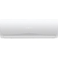
SC-5100AU6A - Air conditioner Seiki - Free user manual and instructions
Find the device manual for free SC-5100AU6A Seiki in PDF.


| Product Type | Split System Air Conditioner |
| Brand | Seiki |
| Model | SC-5100AU6A |
| Cooling Capacity | 5100 W (5.1 kW) |
| Heating Capacity | 5200 W (5.2 kW) |
| Room Size Suitability | 28–32 m² |
| Indoor Unit Dimensions (H x W x D) | 296 x 900 x 222 mm |
| Outdoor Unit Dimensions (H x W x D) | 605 x 850 x 295 mm |
| Indoor Unit Weight | 14 kg |
| Outdoor Unit Weight | 40 kg |
| Voltage / Frequency | 220–240 V AC / 50 Hz |
| Max Cooling Current | 7.0 A |
| Max Heating Current | 6.8 A |
| Max Cooling Power Input | 1504 W |
| Max Heating Power Input | 1480 W |
| Refrigerant Type | R410A |
| Refrigerant Quantity | 1420 g |
| Indoor Unit Noise Level | 42–46 dB(A) |
| Outdoor Unit Noise Level | 55 dB(A) |
| Outdoor Unit Ingress Protection | IP24 |
| Max Discharge Pressure | 4.2 MPa |
| Max Suction Pressure | 1.3 MPa |
| Fuse Rating (Indoor) | 3.15 A / 250 V |
| Fuse Rating (Outdoor) | 20 A / 250 V |
| Minimum Piping Length | 5 m (for standard operation) |
| Self-Diagnosis Functions | Error codes for sensor faults, communication failures, defrost indication |
Frequently Asked Questions - SC-5100AU6A Seiki
User questions about SC-5100AU6A Seiki
0 question about this device. Answer the ones you know or ask your own.
Ask a new question about this device
Download the instructions for your Air conditioner in PDF format for free! Find your manual SC-5100AU6A - Seiki and take your electronic device back in hand. On this page are published all the documents necessary for the use of your device. SC-5100AU6A by Seiki.
USER MANUAL SC-5100AU6A Seiki
natural_image
Exterior view of a white air conditioner unit with digital display and fan inset (no text or symbols)INSTALLATION MANUAL
Please read this manual carefully before using, and keep it for future reference.
CONTENTS
| General | Safety | ||
| Selecting | Installation | Place | |
| Installation | of | Indoor | Unit |
| Installation | of | Outdoor | Unit |
| Is the | Unit | Installed | Correctly? |
| Self Diagnosis | Functions | ||
| Specifications | |||
| Customer | Service | ||
GENERAL SAFETY
Read this manual thoroughly before you start installing the Split system air con.
Store this manual, the completed warranty card, your receipt and the product packaging.
The safety precautions instructions reduces the risk of fire, electric shock and injury when correctly complied to.
Please follow all instructions and take notice of all warnings.
IMPORTANT INFORMATION
These installation instructions for the Air conditioner are for use by an appropriately qualified, licensed installer. The appliance must be installed in accordance with all applicable regulations. Do not try to install the Air conditioner on your own, doing so will expose you to danger and void the warranty.
- Before installing this Aircon, make sure your outlet voltage corresponds to the voltage stated on the power supply rating label.
-
The ratings of the fuse installed in the indoor unit is 3.15A/250V, and outdoor unit is 20A/250V
• DO NOT INSTALL THE UNIT -
In environments where the air could contain gas, oil or sulphur.
- Near sources of heat.
- At a distance of less than 50cm from flammable substances and pressurised containers.
- If the appliance is used in areas without sufficient ventilation, precautions must be taken to prevent any leaks of refrigerant gas from remaining in the environment and creating a fire.
- Make sure that the base of the outdoor unit is firmly fixed.
- Check the air cannot enter the refrigerant system and check for refrigerant leaks when moving the air con unit.
- Ensure that the mains voltage corresponds to that stamped on the rating plate.
- You must protect the indoor unit with a fuse of suitable capacity for the maximum input current or with another overload protection device.
- Carry out a test cycle after installing the air con and record the operating data. Make sure that air cannot enter the refrigerant system and check for any leaks when moving the air con.
SELECTING INSTALLATION PLACE
PROTECT YOUR WARRANTY
These installation instructions for the Air conditioner are for use by an appropriately qualified, licensed installer. Do not try to install the air conditioner on your own; doing so will expose you to danger and void the warranty. Contact a licensed installer.
INDOOR UNIT
• Install the indoor unit level on a strong wall that is not subject to vibrations.
- The inlet and outlet port should not be obstructed, the air should be able to blow all over the room.
- Do not install the unit near a source of heat, steam or flammable gas.
• Install the unit near an electric socket or private circuit.
- Do not not install this unit where it will be exposed to direct sunlight.
- Do no install unit in the laundry.
• Install the unit where connection between indoor and outdoor unit is easy.
• Install unit where it is easy to drain condensation water.
• Install unit where the filter can be easily accessed.
SELECTING INSTALLATION PLACE (Cont.)
OUTDOOR UNIT
• DO NOT INSTALL THE UNIT
Near heat sources, steam or flammable gas.
Exposure to high winds or dust.
- Avoid installing in direct sunlight.
- Where the air discharge and sound level will not disturb neighbours.
- Leave minimum clearences around the unit for free air circulation.
- If the outdoor unit is vibrating, place rubber gaskets on the feet of the unit.
- The method of fixing is not to depend on the use of adhesives since they are not considered to be a reliable fixing means.
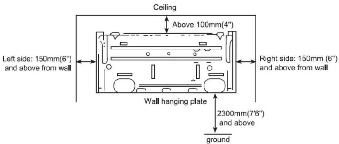
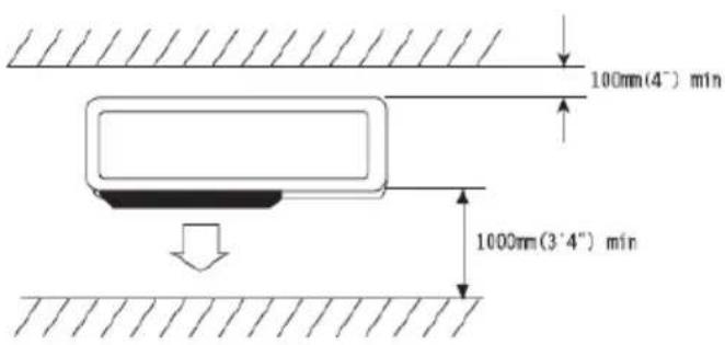
MINIMUM DISTANCES FOR INSTALLATION
- When there are obstacles above the unit

- When the front (air outlet) is open

- When there are obstacles only in the front (air outlet)

Space for maintenance
Shown as in the following figure. Keep the maintenance space in front of the unit.

- When there are obstacles at the front and rear sides.
- When there are obstacles all around the unit on four sides.
Although the top side is open, the installation is not to be done if there are obstacles all around.
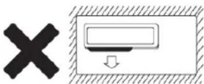
● At least two sides should be kept open.
INSTALLATION OF INDOOR UNIT
1. Installation of Wall Mounting Plate
- Make sure the plate is completely level by using a spirit level, if mounting plate is slanted it can hinder the smooth discharge of the condensed water.
- Mark and drill mounting holes corresponding with the mounting holes in the mounting plate.
- Fix the wall mounting plate firmly on the wall with screws.
The method of fixing is not to depend on the use of adhesives since they are not considered to be a reliable fixing means. *(Mounting hardware not supplied)
2. ACCESS TO PIPING
- Drill holes at places slightly below the wall mounting plate corresponding with where the piping and drain outlet exit the indoor unit with hole diameter of 65mm starting from the inside wall, and make the outside wall 5-10mm lower so the water can smoothly flow out.
- Cut the wall penetrating pipe to correct length according to the thickness of the wall and add 5mm extra length longer then the wall thickness and insert the pipe as indicated.

3. INSTALLATION OF DRAIN PIPE
• Install the piplines of the indoor unit in accordance with the wall hole.
- Wrap tightly the drain pipe and the pipelines with trap, Make sure the drain pipe is underneath the pipelines of indoor unit.

INSTALLATION OF INDOOR UNIT (Cont.)
4. INSTALLATION OF INDOOR UNIT
• Pass the connection wires, connecting pipelines and drain pipe through the wall hole.
- Hang the indoor unit on the hook of the top of the wall mounting plate so that the hooks at the bottom of the indoor unit match the hook of the wall mounting plate.

5. INSPECTIONS
- Check if the hooks on the mounting plate and unit at the top or bottom are firmly fixed.
- Check that the indoor unit is properly level.
- The drain pipe should not curve upward (refer to picture below).
- The drain pipe should be at the lower part of the wall pipes. (refer to below).

INSTALLATION OF OUTDOOR UNIT
- Use caution when hoisting cables to lift the unit as the centre of balance is not at the installation centre.
- Use expansion bolts to fix the mounting supports on the wall.
- Use bolts and nuts to fix the outdoor unit firmly on the supports and keep on the same level.
- If the unit is installed on the wall or rooftop, the supports have to be firmly fixed so it can resist strong weather conditions.

ORDINARY PIPELINE CONNECTIONS AND AIR PURGING
No dust, foreign objects, air or moisture should be allowed to enter the air conditioning system. Careful attention should be paid when the pipeline connection to the outdoor unit is made. Try to avoid curves as much as possible, as hardening or cracks may occur to the copper pipes. Suitable wrenches should be used when the pipeline connection is done, so as to ensure appropriate torque (refer to torque table below). Excessive torque may damage the joints, while too little torque may lead to leakage.
TORQUE BASED UPON THE WRENCH TO BE USED
| Outer diameter of copper pipe | Tightening torque | Strengthened tightening torque |
| ∅ 6.35(1/4") | 160kgf.cm(63kgf.inch) | 200kgf.cm(79kgf.inch) |
| ∅ 9.52(3/8") | 300kgf.cm(118kgf.inch) | 350kgf.cm(138kgf.inch) |
| ∅ 12.7(1/2") | 500kgf.cm(197kgf.inch) | 550kgf.cm(216kgf.inch) |
| ∅ 15.88(5/8") | 750kgf.cm(295kgf.inch) | 800kgf.cm(315kgf.inch) |
| ∅ 19.05(3/4") | 1200kgf.cm(472kgf.inch) | 1400kgf.cm(551kgf.inch) |
INSTALLATION OF OUTDOOR UNIT (Cont.)
- Check that the pipeline connections have been properly connected. Remove the charging port cap, then connect the manifold gauge and the vacuum pump to the charging valve by the service hoses, (shown in drawing).
2.Open the valve on the low pressure side of the manifold gauge, then run the vacuum pump. Vacuum the indoor unit and the connecting pipes until the pressure in them lowers to below
1.5mmGH (the operation time for this should be about 10 minutes).
When the desired vacuum level is reached, close the low pressure valve on the manifold, then stop the vacuum pump.
-
Disconnect the service hoses, then fit the cap to the charging valve.
-
Remove the blank caps, then fully open the spindles on the 2-way and 3-way valves with a service valve wrench.
-
Tighten the blank caps on the 2-way and 3-way valves, according to the previous torque Table 1.

ADDING REFRIGERANT
Refrigerant must be added if the piping measures more than 5 metres (16'5") in length. This operation can only be performed by a professional technician. For the refrigerant amount, please refer to the table below.
| Additional Refrigerant Amount | |
| Liquid pipe diameter ∅6.35 (1/4") Liquid pipe | diameter ∅9.52 (3/8") |
| (piping length-5)mx30gor (piping length-16)ftx0.3oz | (piping length-5)mx65gor (piping length-16)ftx0.7oz |
INSTALLATION OF OUTDOOR UNIT (Cont.)
GAS LEAKAGE INSPECTION
After the pipeline connections are done, use a leakage inspection device or soap suds to carefully check if there is any leakage at any joints. This is an important step to ensure the quality of the installation. Once a leakage is detected, proper treatment should be taken immediately.
PIPELINE CONNECTIONS FOR SPLIT TYPE QUICK COUPLER
If you purchase the unit for split type quick couple model, please follow these pipeline connection procedures:
- Remove the dust caps from the indoor and outdoor units, and the connecting pipe.
-
Align the joint counter of the connecting pipe with the proper indoor and outdoor joint conic surfaces, tightening the connecting nut manually. Then make is secure with a wrench (as shown in drawing), according to the torque Table on page 10.
-
Remove the two valve core caps from the outdoor unit.
-
Turn the high and low pressure valve cores with a socket wrench, then tighten the two valve core caps of the outdoor unit (Fig 8).
-
Finally, wrap hot insulating cotton around the joints of the indoor and outdoor units.


- See the connecting pipe bending minimum radius parameters.
- Quick coupler assembly and disassembly limit: the assembly and disassembly times are inadvisably more than 7.
| Normal Diameter (mm) Minimum Bending Radius (mm) Cooling Capacity | ||
| DN10-12(1/2") 100 (4") 2500 | ~ 5100W | (9000-18000BTU) |
INSTALLATION OF OUTDOOR UNIT (Cont.)
CONNECTION OF POWER CABLE
-
Remove the connection panel of the outdoor unit.
-
Non-quick Coupler: Connect the indoor power and control wires with the matching outdoor wires in accordance with the electric schematic diagram on each unit, making sure that the connection is secure.
Quick Coupler: Directly connect the quick cable couplers with indoor and outdoor quick cable couplers after the disassembly of the outdoor unit.
-
Use a press plate to fix the wires firmly into place, then reinstall the connection panel.
-
Option steps: If present in the unit, you should connect the indoor wire connector with the outd probe wire connector for defrosting.


natural_image
Pure mechanical component diagram showing internal structure and assembly without any text or symbolsWARNING
- Do not connect the wires the wrong way around, otherwise malfunction or damaging the unit can occur.
- The appliance shall be installed in accordance with national wiring regulations.
- If the supply cord is damaged, it must be replaced by the manufacturer or a qualified service agent in order to avoid hazard.
INSTALLATION OF OUTDOOR UNIT (Cont.)
FINAL TOUCHES
- Wrap the pipelines tightly with ethylene tape.
- Fix the wrapped pipelines to the exterior walls with clamps.
- Fill in any gaps left over from the pipeline holes in the wall to prevent rain water from entering and from air drafts.
TEST RUNNING
- Connect units to power, then check that the function selection keys on the remote control are working correctly.
- Check that the room temperature adjustments and timer settings are working correctly.
- Check that the drainage system is smooth and operational.
- Check for any abnormal noises, vibrations or smells.
- Check for any leakage of refrigerant.
IS THE UNIT INSTALLED CORRECTLY?
SUITABLE INSTALLATION POSITION
- Is there anything that prevents ventilation, or obstructs operation and effective air flow in front of the indoor unit?
- Do not install in locations where flammable gases may leak or oil splashes often.
- In seaside districts where sea breezes will be encountered by the unit, the high salt content in the air often leads to early corrosion. Please monitor the unit over time.
- The air-conditioner should be at least 1 metre away from TVs or radios.
- The dehumidified water should be drained into a location that drains water well.
OPERATION NOISE
- When installing the unit, choose a location that can stand the weight of the unit, that will not increase the operation noise or vibration. If the vibrations are transmitted to the house itself, place the unit with vibration-proof pads (not supplied) between the unit and the fittings.
- Choose the place where hot air and operation noise from the outlet of the outdoor unit does not annoy neighbours.
- Things left near the outlet and inlet of the outdoor unit may cause malfunction or increased operation noise.
- If irregular sound is heard during operation, contact our customer support centre.
INSPECTION AND MAINTENANCE
- According to operating environments the inside of the air conditioner will become dirty after a few years (3-5) of service, which will result in decreased operating performance. Inspection and maintenance are recommended in addition to the usual cleaning.
- Only use qualified air conditioner technicians to inspect and perform maintenance checks on your air conditioner and commenced during the off-season period when aircon is not in use.
- Ensure all indoor and outdoor units have been switch off from the power source before any inspection or cleaning is carried out.
SELF DIAGNOSIS FUNCTIONS
The air-conditioner has sensors and a self diagnosis system which will display error codes when an issue is detected.
| Self Check Information Indi cator Behaviour Error Code Behaviour | ||
| Defrost Indication 1 flash per second “dF” or a Heating icon | ||
| Room Temperature Sensor Fault | 1 flash per second E2 | |
| Coil Temperature Sensor 1 flash per 8 seconds E3 | ||
| External Feedback Fault 7 flashes per 8 seconds E7 | ||
| Outdoor Tube Temperature Sensor Faults | 4 flashes per 8 seconds E1 | |
| (EEPROM) Communication failures | 6 flashes per 8 seconds E6 | |
| Outside Temperature exceeds operational range | 1 flash per second | FF |
SPECIFICATIONS
| Capacity | COOLING 5100W (5.1kW) | |
| HEATING 5200W (5.2kW) | ||
| Max. Current Input | COOLING 7.0 A | |
| HEATING 6.8 A | ||
| Max. Power Input | COOLING 1504 W | |
| HEATING 1480 W | ||
| Room Size Suitability | 28-32 m^2 | |
| Rated Voltage and Frequency | 220-240V AC / 50Hz | |
| Ingress Protection | OUTDOOR UNIT IP24 | |
| Net Weight | INDOOR UNIT | 14 kg |
| OUTDOOR UNIT 40 kg | ||
| Max. Pressure | DISCHARGE 4.2 MPa | |
| SUCTION 1.3 MPa | ||
| Refrigerant Type | TYPE R410A | |
| QUANTITY 1420 g | ||
| Noise Level | INDOOR UNIT 42-46 dB(A) | |
| OUTDOOR UNIT 55 dB(A) | ||
| Dimensions | INDOOR UNIT (mm) 296 (h) x 900 (w) x 222 (d) | |
| OUTDOOR UNIT (mm) 605 (h) x 850 (w) x 295 (d) | ||
[Non-Text]
[Non-Text]
[Non-Text]
[Non-Text]
[Non-Text]
[Non-Text]
[Non-Text]
[Non-Text]
[Non-Text]
[Non-Text]
[Non-Text]
[Non-Text]
[Non-Text]
[Non-Text]
[Non-Text]
[Non-Text]
[Non-Text]
[Non-Text]
[Non-Text]
[Non-Text]
[Non-Text]
[Non-Text]
[Non-Text]
[Non-Text]
[Non-Text]
[Non-Text]
[Non-Text]
[Non-Text]
[Non-Text]
[Non-Text]
[Non-Text]
[Non-Text]
[Non-Text]
[Non-Text]
[Non-Text]
[Non-Text]
[Non-Text]
[Non-Text]
[Non-Text]
[Non-Text]
[Non-Text]
[Non-Text]
[Non-Text]
[Non-Text]
[Non-Text]
[Non-Text]
[Non-Text]
[Non-Text]
[Non-Text]
[Non-Text]
[Non-Text]
[Non-Text]
[Non-Text]
[Non-Text]
[Non-Text]
[Non-Text]
[Non-Text]
[Non-Text]
[Non-Text]
[Non-Text]
[Non-Text]
[Non-Text]
[Non-Text]
[Non-Text]
17
[Non-Text]
[Non-Text]
[Non-Text]
17
17
[Non-Text]
[Non-Text]
[Non-Text]
[Non-Text]
[Non-Text]
[Non-Text]
[Non-Text]
[Non-Text]
[Non-Text]
[Non-Text]
[Non-Text]
[Non-Text]
[Non-Text]
[Non-Text]
[Non-Text]
[Non-Text]
[Non-Text]
[Non-Text]
[Non-Text]
[Non-Text]
[Non-Text]
[Non-Text]
[Non-Text]
[Non-Text]
[Non-Text]
[Non-Text]
[Non-Text]
[Non-Text]
[Non-Text]
[Non-Text]
[Non-Text]
17
(1) AD = BD = 1
[Non-Text]
[Non-Text]
[Non-Text]
17
17
17
17
17
[Non-Text]
[Non-Text]
[Non-Text]
[Non-Text]
[Non-Text]
[Non-Text]
[Non-Text]
[Non-Text]
[Non-Text]
[Non-Text]
[Non-Text]
[Non-Text]
[Non-Text]
[Non-Text]
[Non-Text]
[Non-Text]
[Non-Text]
[Non-Text]
[Non-Text]
[Non-Text]
[Non-Text]
[Non-Text]
[Non-Text]
[Non-Text]
[Non-Text]
[Non-Text]
[Non-Text]
[Non-Text]
[Non-Text]
[Non-Text]
[Non-Text]
[Non-Text]
[Non-Text]
[Non-Text]
[Non-Text]
[Non-Text]
[Non-Text]
[Non-Text]
[Non-Text]
[Non-Text]
[Non-Text]
19
[Non-Text]
[Non-Text]
[Non-Text]
19
19
[Non-Text]
[Non-Text]
[Non-Text]
[Non-Text]
[Non-Text]
[Non-Text]
[Non-Text]
[Non-Text]
[Non-Text]
[Non-Text]
[Non-Text]
[Non-Text]
[Non-Text]
[Non-Text]
[Non-Text]
[Non-Text]
[Non-Text]
[Non-Text]
SEIKI™
CUSTOMER HELPLINE:
1300 296 699
DISTRIBUTED BY:
AYONZ PTY LTD

- INSTALLATION MANUAL
- CONTENTS
- GENERAL SAFETY
- IMPORTANT INFORMATION
- SELECTING INSTALLATION PLACE
- PROTECT YOUR WARRANTY
- INDOOR UNIT
- SELECTING INSTALLATION PLACE (Cont.)
- OUTDOOR UNIT
- • DO NOT INSTALL THE UNIT
- MINIMUM DISTANCES FOR INSTALLATION
- INSTALLATION OF INDOOR UNIT
- Installation of Wall Mounting Plate
- ACCESS TO PIPING
- INSTALLATION OF DRAIN PIPE
- INSTALLATION OF INDOOR UNIT (Cont.)
- INSTALLATION OF INDOOR UNIT
- INSPECTIONS
- INSTALLATION OF OUTDOOR UNIT
- ORDINARY PIPELINE CONNECTIONS AND AIR PURGING
- INSTALLATION OF OUTDOOR UNIT (Cont.)
- ADDING REFRIGERANT
- GAS LEAKAGE INSPECTION
- PIPELINE CONNECTIONS FOR SPLIT TYPE QUICK COUPLER
- CONNECTION OF POWER CABLE
- WARNING
- FINAL TOUCHES
- TEST RUNNING
- IS THE UNIT INSTALLED CORRECTLY?
- SUITABLE INSTALLATION POSITION
- OPERATION NOISE
- INSPECTION AND MAINTENANCE
- SELF DIAGNOSIS FUNCTIONS
- SPECIFICATIONS
- SEIKI™
Brand : Seiki
Model : SC-5100AU6A
Category : Air conditioner