EPM-3790N - Measurement Emko - Free user manual and instructions
Find the device manual for free EPM-3790N Emko in PDF.

| Product Type | Digital Multimeter |
| Brand | Emko |
| Model | EPM-3790N |
| Display Type | LCD, 3 1/2 digits (1999 counts) |
| DC Voltage Range | 200mV, 2V, 20V, 200V, 600V |
| AC Voltage Range | 200mV, 2V, 20V, 200V, 600V |
| DC Current Range | 200μA, 2mA, 20mA, 200mA, 10A |
| Resistance Range | 200Ω, 2kΩ, 20kΩ, 200kΩ, 2MΩ, 20MΩ |
| Capacitance Measurement | 2nF to 200μF |
| Frequency Measurement | 2kHz to 20MHz |
| Temperature Measurement | -20°C to 1000°C (with type K thermocouple) |
| Diode Test | Yes |
| Continuity Buzzer | Yes, threshold < 50Ω |
| Overload Protection | Yes, on all ranges |
| Power Supply | 9V battery (NEDA 1604) |
| Battery Life | Approximately 200 hours (carbon-zinc) |
| Dimensions (HxWxD) | 150mm x 70mm x 30mm |
| Weight | 200g (including battery) |
| Safety Rating | CAT II 600V |
| Operating Temperature | 0°C to 40°C |
| Storage Temperature | -10°C to 50°C |
| Accessories Included | Test leads, temperature probe (type K), 9V battery, user manual |
| Warranty | 1 year |
| Cleaning | Wipe with a dry, soft cloth. Do not use solvents. |
| Maintenance | Replace battery when low battery indicator shows. Calibration recommended annually. |
Frequently Asked Questions - EPM-3790N Emko
User questions about EPM-3790N Emko
0 question about this device. Answer the ones you know or ask your own.
Ask a new question about this device
Download the instructions for your Measurement in PDF format for free! Find your manual EPM-3790N - Emko and take your electronic device back in hand. On this page are published all the documents necessary for the use of your device. EPM-3790N by Emko.
USER MANUAL EPM-3790N Emko
| 7. Motor Start Stop Configuration | |
| Device Type | General Panel 40, VIF Select Corridor From a 35mm x 52mm Plate marking for panel Mounting Panel output x 67x120 mm |
| Protection Break | |
| Mechanical Impacts | (12mm x 90mm) |
| Protection Clairs | M-Box x 40mm and mm (120mm x 5mm) |
| Weight | Approximate 100 gm |
| Environmental Rating | Standard, above or below each from 2800 mm |
| W/1: 1000 mm (1000 mm x 1000 mm x 1000 mm x 1000 mm x 1000 mm x 1000 mm x 1000 mm x 1000 mm x 1000 mm x 1000 mm x 1000 mm x 1000 mm x 1000 mm x 1000 mm x 1000 mm x 1 | |
| Storage / Operating Temperature | 40°C to +56.0 °C to +45°C |
| Storage / Operating Humidity | All max. (Low - Moderate) |
| Installation | Hand Inverter |
| Overcharge Category | L |
| Pollution Grade | 1. Choice or microwave, name constructed pollution |
| Scale | Between -500 and 8500 |
| Intrusive Output | 500-1000 mm (1000 mm x 1000 mm x 1000 mm x 1000 mm x 1000 mm x 1000 mm x 1000 mm x 1000 mm x 1000 mm x 1000 mm x 1000 mm x 1000 mm x 1000 mm x 10 |
| Digital Output | Standard Direction Data (low, mean=500x250V) |
| Reverse Direction Data (high, mean=500x250V) | |
| Digital Input | Input input (low, mean=500x250V) |
| Max. 14.5mm (Low - Moderate) | |
| Max. (Low 1.5mm x 500mm) | |
| Resolution | 12 bits |
| Fluctuation | 30 nm |
| Supply Voltage and Power | 230V~244V (5000Hz, 2.5VA) |
| 185V~195V (500Hz, 2.5VA) | |
| 200V~210V (500Hz, 2.5VA) | |
| 240V~250V (500MHz, 2.5VA) | |
| 30V~35V, 2.5VA | |
| Display | 10 mm and 40 dB LED |
| LEDs | Recommended (with labels a green)/ament |
| Compliance | BE = CE |
| A | Power Supply | ||||||||
| 2 | 24V~ | [±5/15] 50/60Hz - 2.5VA | |||||||
| 3 | 24V~ | [±5/15] 50/60Hz - 2.5VA | |||||||
| 4 | 115V~ | [±5/15] 50/60Hz - 2.5VA | |||||||
| 5 | 230V~ | [±5/15] 50/60Hz - 2.5VA | |||||||
| 6 | 10-30V~ | -2.5W | |||||||
| 9 | Customer Specification | ||||||||
| E | Output | ||||||||
| 4 | Current Output (0V, 25mA) | ||||||||
| 5 | Voltage Output (8Ω, 12V max, 10 mA) | ||||||||
| EPM-3790N 77x35 DIN Size Control Panel For V/F Speed Controller | |
| 2500 | |
| -4 Digital Display -Adjustable electrical point -Set value low limit and set value high limit boundaries -Adjustable ramp up and ramp down Size -Exactly adjustable net value from front panel -Configurable display scale between -1935 and 2003 -Forward, Reverse direction outputs and other input for V/F Speed Controller -PZ-10V — Voltage output or S4-20mA — Current output (if must be specified to order) -Password protection for programming and settings sections |
| 1.1 Operating Conditions | |
| Operating Temperature | -100°C |
| Max. Operating Humidity | -90% (non-conditions) |
| Albide Up to 2000m | |
| Forbidden Conditions | |
| Conventional serotypes | |
| Exploration serotypes | |
| Home applications (The unit is only for individual applications) | |
| 1.3 Installation | |
| ### | Before the main mode of this product, please contact the manufacturer and using a manual truck. |
| ### | ### |
| ### | ### |
| ### | ### |
| ### | ### |
| ### | ### |
| ### | ### |
| ### | ### |
| ### | ### |
| ### | ### |
| ### | ### |
| ### | ### |
| ### | ### |
| ### | ### |
| ### | ### |
| ### | ### |
| ### | ### |
| ### | ### |
| ## | ### |
| ### | ### |
| ### | ### |
| ### | ### |
| ### | ### |
| ### | ### |
| ### | ### |
| ### | ### |
| ### | ### |
| ### | ### |
| ### | ### |
| ### | ### |
| ### | ### |
| ### | ### |
| ### | ### |
| ### | ### |
| ### | ### |
| 2.1 Front View and Dimensions of FPIA-3790 Unit | |
| 8.888 | Maximum thickness 15 mm (6.53 inch) |
| New 1 inch | 15mm x 2.50 inch |
| 2.2 Panel Cut-Out | |
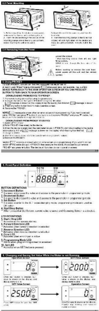
1. Using PROKEY
TO USE PROPER, VALUE OF THE PIC PARAMETER MUST BE V.
\$ PRICE AND WRITTEN IS PRESSED □ □ VENSAGE WILL BE SHOWN. 500, LATER
DEVICE TURNS BACK TO THE WORK OPERATION SERVICE
-
The company's registered by Japan
-
Surge the door to the panel P/KEY 2011/03/25.
-
Most provisions in the bank may require a copy
-
Balance in CROUPE
2.1.1. 2017年1月1日
NOTE: I change a question what is now once as a preparing. If you were mixed.
-
Dif in FROUER than seen to the device
-
When the device is expected, the parameter value is P_200 × 10^-4 , and downloading to the order
what is all of [□] manage a short time slide, when having been limited.
105420 6 STANY.
4.10% of 3,500.5 dollars to \$2.00 in developed FA (2007) values
- 2017年1月1日
switch of the service and put a PROPERTY then being on the device. If you want to put new
PROFEY are praus whalim. The deals will lambec to re transfer on screen
注册号:10
BUTTON DEFINITIONS
- Increment Button
“The mean in the case for the effect and outcome is the parameter in programming mode
- Decrement Button
This uses to decrease the value and access to the parameter in programming mode
- Get Button "I is enough to help in the
(2) 10.3.15
-
SprayStop Button
-
After announced at 3rd Screen, current sales are sold and Operating Screen is accounted
(五) 本次股东大会的召集和召开程序
LED DEFINITIONS
- Start/Stop LED
“Azileks al Pro apion aberi-
- Forward Direction LED
"Advisiae abact inwest dinest but is standard"
- Reverse Direction LED
- ACTUALS WITH REACH CHOCOMIS SELECTED - Focal EFR
-
ENSLED
-
Promotion Mode LED
-
Programming Noise LED ** While when the following is necessary
-
Set LED
"Methodea when BET button to proposed

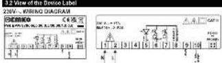
- Electrical Wiring

text_image
PN. EPI-3NM 24V, 20mA Output 20V, 15mA Output 2ND Voltage Input Forward Direction Output Reverse Direction Output Error Input Supply Voltage Input 200V, 100V, 100Hz 1.2V, 50Hz, 50Hz 24V, 10V, 100Hz4.1 Supply Voltage Input Connection of the

text_image
Conversion of Supply Voltage Input External Power Supply Voltage 23V~ (A 50Hz) 1600 Hz Power Supply Switch More used for the power supply voltage in low- to medium level (a) the circuit started at the power supply only, then had a small electrical component connected to the output. Supply voltage ranges from 1 to 400 V, and the circuit is designed as an equivalent supply voltage range. The output is applied to the unit and corresponding voltage source. The current of the power supply and possible conversion output of the power supply voltage. More in the power supply, it is not a high-voltage device, but the power supply voltage is also included in the supply voltage range and power supply voltage range. We have been placed at the same level for our current. Power supply voltage will be taken by a power plant containing phase currents. On current of the power supply, this is very important in electrical equipment, which is used in the power supply management.115 V\~ (2415) 5000 Hz Central bus bus bus bus bus bus bus bus bus bus bus bus bus bus bus bus bus bus bus bus bus bus bus bus bus bus bus bus bus bus bus bus bus bus bus bus bus bus bus bus bus bus bus bus bus bus bus bus bus bus bus bus bus bus bus bus bus bus bus bus bus bus bus bus bus bus bus bus bus bus bus bus bus bus bus bus bus bus bus bus bus bus bus bus bus bus bus bus bus bus bus bus bus bus bus bus bus bus bus bus
24 V… (± %15) SDSD Hz,
24 V = (-S15, + S10) 5080 Hz
Note-1: Electrical line is recommended
The company has a 2-to-10%
Note 3. Supply stock next quarter with the investments of IEC 65277 or IEC 50015
2.010s of the Driven Bank
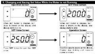
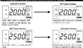
6.1. Changing and Saving Set Value While the Motor is Running
text_image
Operation Screen 2000 CT Value Screen 2000 When SCT value is shown, SCT value is shown in the display, and display is set off. Charge the SCT value and screen connected to the screen. SCT Time Screen 2500 Operation Screen 2500 When SCT value is shown for SCT temperature, it is shown in the display, and display is set off.Error Set Parameter [Default:2001] MODELS ADDRESS:40021
2017.4.2018 [Jenlin 2019] MoBee He###30:4091
If let me be changed on the other number, we can put a effect on the shape by
bar
| Category | Percentage (%) | | :--- | :--- | | DIRECTION | 100 | | ANALYSIS OUTPUT | 25 | | DIGITAL OUTPUT | 10 | | RISKING | 25 | | DATA OUTPUT | 10 | | RISKING OUTPUT | 25 | | DATA OUTPUT | 10 | | RISKING OUTPUT | 25 | | DATA OUTPUT | 10 | | RISKING OUTPUT | 25 | | DATA OUTPUT | 10 | | RISKING OUTPUT | 25 | | DATA OUTPUT | 10 | | RISKING OUTPUT | 25 | | DATA OUTPUT | 10 | | RISKING OUTPUT | 25 | | DATA OUTPUT | -10 | | RISKING OUTPUT | -10 | | DATA OUTPUT | -10 | | RISKING OUTPUT | -10 | | DATA OUTPUT | -10 | | RISKING OUTPUT | -10 | | DATA OUTPUT | -10 | | RISKING OUTPUT | -10 | | DATA OUTPUT | -10 | | RISKING OUTPUT | -10 | | DATA OUTPUT | -10 | | RISKING OUTPUT | -10 | | DATA OUTPUT | -10 | | | RISKING OUTPUT | -10 | | | DATA OUTPUT | -10 | | | RISKING OUTPUT | -10 | | | DATA OUTPUT | -10 | | | RISKING OUTPUT | -10 | | | DATA OUTPUT | -10 | | | RISKING OUTPUT | -10 | | | DATA OUTPUT | -10 | | | RISKING OUTPUT | -10 | | | DATA OUTPUT | -10 | | | RISKING OUTPUT | -10 | | DATA OUTPUT | -10 | | | RISKING OUTPUT | -10 | | | DATA OUTPUT | -10 | | | RISKING OUTPUT | -10 | | | DATA OUTPUT | -10 | | | RISKING OUTPUT | -10 | | | DATA OUTPUT | -10 | | | RISKING OUTPUT | -10 | | | DATA OUTPUT | -10 | | | RISKING OUTPUT | -10 | | | DATA OUTPUT | -10 | | RISKING OUTPUT | -10 | | | DATA OUTPUT | -10 | | RISKING OUTPUT | -10 | | | DATA OUTPUT | -10 | | RISKING OUTPUT | -10 | | | DATA OUTPUT | -10 | | RISKING OUTPUT | -10 | | | DATA OUTPUT | -10 | | RISKING OUTPUT | -10 | | | DATA OUTPUT | -10 | | RISKING OUTDOCTORS DATA OUTDOCTORS DIGITAL OUTDOCTORS RISKING OUTDOCTORS DATA OUTDOCTORS DIGITAL OUTDOCTORS RISKING OUTDOCTORS DATA OUTDOCTORS DIGITAL OUTDOCTORS RISKING OUTDOCTORS DATA OUTDOCTORS DIGITAL OUTDOCTORS RISKING OUTDOCTORS DATA OUTDOCTORS DIGITAL OUTDOCTORS RISKING OUTDOCTORS DATA OUTDOCTORS DIGAL OUTDOCTORS DIRECTION Selection: Default = & YANOGUS ADDRESS : 46936 Direction Selection: Default = & YANOGUS ADDRESS : 46936Major Direction Changes (this - 1)
flowchart
graph TD
    A["Patient Screening"] --> B{Patients: 1.2M (2000), 3.5M (4000), 6.0M (7000), 9.5M (10000) = 1.5M; 1.8M (2.1M, 2.4M, 2.7M, 3.1M, 3.4M, 3.7M); 4.0M (4.3M, 4.6M, 4.9M, 5.2M, 5.5M, 5.8M, 6.1M, 6.4M, 6.7M, 7.0M, 7.3M, 7.6M, 7.9M, 8.2M, 8.5M, 8.8M, 9.1M, 9.4M, 9.7M, 10.0M, 10.3M, 10.6M, 10.9M, 11.2M, 11.5M, 11.8M, 12.1M, 12.4M, 12.7M, 13.0M, 13.3M, 13.6M, 13.9M, 14.2M, 14.5M, 14.8M, 15.1M, 15.4M, 15.7M, 16.0M, 16.3M, 16.6M, 16.9M, 17.2M, 17.5M, 17.8M, 18.1M, 18.4M, 18.7M, 19.0M, 19.3M, 19.6M, 19.9M, 20.2M, 20.5M, 20.8M, 21.1M, 21.4M, 21.7M, 22.0M, 22.3M, 22.6M, 22.9M, 23.2M, 23.5M, 23.8M, 24.1M, 24.4M, 24.7M, 25.0M, 25.3M, 25.6M, 25.9M, 26.2M, 26.5M, 26.8M, 27.1M, 27.4M, 27.7M, 28.0M, 28.3M, 28.6M, 28.9M, 29.2M, 29.5M, 29.8M, 29.9M, 30.2M, 30.5m
    B --> C{Patients: ≥3 M (≥3 M), ≥4 M (≥4 M), ≥5 M (≥5 M), ≥6 M (≥6 M), ≥7 M (≥7 M), ≥8 M (≥8 M), ≥9 M (≥9 M), ≥10 M (≥10 M), ≥11 M (≥11 M), ≥12 M (≥12 M), ≥13 M (≥13 M), ≥14 M (≥14 M), ≥15 M (≥15 M), ≥16 M (≥16 M), ≥17 M (≥17 M), ≥18 M (≥18 M), ≥19 M (≥19 M), ≥20 M (≥20 M), ≥21 M (≥21 M), ≥22 M (≥22 M), ≥23 M (≥23 M), ≥24 M (≥24 M), ≥25 M (≥25 M), ≥26 M (≥26 M), ≥27 M (≥27 M), ≥28 M (≥28 M), ≥29 M (≥29 M), ≥30 M (≥30 M), ≥31 M (≥31 M), ≥32 M (≥32 M), ≥33 M (≥33 M), ≥34 M (≥34 M), ≥35 M (≥35 M), ≥36 M (≥36 M), ≥37 M (≥37 M), ≥38 M (≥38 M), ≥39 M (≥39 M), ≥40 M (≥40 M)
    C --> D{Patients: ≥3 M (≥3 M), ≥4 M (≥4 M), ≥5 M (≥5 M), ≥6 M (≥6 M), ≥7 M (≥7 M), ≥8 M (≥8 M), ≥9 M (≥9 M), ≥10 M (≥10 M), ≥11 M (≥11 M), ≥12 M (≥12 M), ≥13 M (≥13 M), ≤30% >5% >5% >5% >5% >5% >5% >5% >5% >5% >5% >5% >5% >5% >5% >5% >5% >5% >5% >5% >5% >5% >5% >5% >5% >5% >5% >5% >5% >5% >5% >5% >5% >5% >5%
    D --> E{Patients: ≥3 M (≥3 M), ≥4 M (≥4 M), ≥5 M (≥5 M), ≥6 M (≥6 M), ≥7 M (≥7 M), ≥8 M (≥8 M), ≥9 M (≥9 M), ≤40% >5% >5% >5% >5% >5% >5% >5% >5% >5% >5% >5% >5% >5% >5%
    E --> F{Patients: ≥3 M (≥3 M), ≥4 M (≥4 M), ≥5 M (≥5 M), ≥6 M (≥6 M), ≤40% >5% >5% >5% >5% >5% >5% >5% >5% >5%
    F --> G{Patients: ≥3 M (≥3 M), ≥4 M (≥4 M), ≤40% >5% >5% >5% >5% >5% >5% >5%
    G --> H{Patients: ≥3 M (≥3 M), ≤40% >5% >5% >5% >5% >5% >5%
    H --> I{Patients: ≤40% >5% >5% >5% >5% >5%
    I --> J{Patients: ≤40% <5% >5% >5% >5% >5%
    J --> K{Patients: ≤40% <6% >6%>6%
    K --> L{Patients: ≤40% <7%
    L --> L
    L --> L
    L --> L
    L --> L
    L --> L
    L --> L
    L --> L
    L --> L
    L --> L
    L --> L
    L --> L
    L --> L
    L --> L
    L --> L
    L --> L
    L --> L
    L --> L
    L --> L
    L --> L
DCCC Programming Section Accessing Password
(Default=0)
It is used for ensuring in the programming sector. It can be adjusted from
015-2083
If this passwd is 0, programming sector can be processed without ordering
ITN RESEARCH
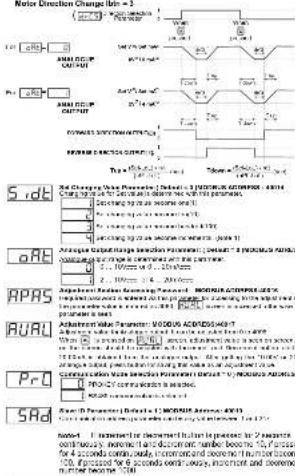
Direction Change Delay Time Parameter:
In a few hours, there were a shop, then that was read you to operate again.
in other direction. It can be adjusted from 1 to 200 msec
Ramp Up Time Parameter: Default = 10sec.
FUE Increasing time of the analogue curve from 0V to 10V or 0mA to 20mA is
determined with this parameter, it can be applied from 1 in 259 sec.
- 15. Range Demo Tree Parameters! Default = 10x90
rde Decreasing time of the course out from 10% to 20% in 6m4
- D.C. Lening and C. H. Chugal Ossisman 10, 12, 61 of 2014 to
In addition to matrix parameters: Total of squares with 1 × 200 sets.
In the following table is the main components of the
-
-
-
-
-
-
-
-
-
-
-
-
-
-
-
-
-
-
-
-
-
-
-
-
-
-
-
-
-
-
-
-
-
-
-
-
-
-
-
-
-
-
-
-
-
-
-
-
-
-
-
-
-
-
-
-
-
-
-
-
-
-
-
-
-
-
-
-
-
-
-
-
-
-
-
-
-
-
-
-
-
-
-
-
-
-
-
-
- 90.
-
-
-
-
-
-
-
-
-
-
-
-
-
-
-
-
-
-
-
-
-
-
-
-
-
-
-
-
-
-
-
-
-
-
-
-
-
-
-
-
-
-
-
-
-
-
-
-
-
-
-
-
-
-
-
-
-
-
-
-
-
-
-
-
-
-
-
-
-
-
-
-
-
-
-
-
-
-
-
-
-
-
-
-
-
-
-
-
2017年10月31日
____
____; Ansepture calper, a directly annotated in bad year when the present Indian
____ is prezec
2 Analog output is increased to Set Value according to the ramp-up time when
In connection button is pressed
Direction of the movement is changed when increment button is pressed.
(一)公司董事会会议决议公告
☐ JLL ☐ Decrement Button Parameter for Functional Usage: (Default=2)
D.D.C.1 Usage of the Document button while the motor is running and the unit is on
operation screen
(1) Decrement subon is disabled
- An average output is directly adjusted in minimum set value when decreased
—
- Australian school, a department, a former-to-solar security in the public
the company's major decision-making process
text_image
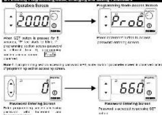
Decrement Buffer Functional Image s(t=0) s(t=1) s(t=2) t=3 S(t=0) A(A)C(1)(2) OUTPUT S(t=0) 2nd (50Hz) when processed processed when processed processed when processed processed processed T down T up6.4 Entering Programming Mode, Changing and Saving Parameters