
DS-TDSB00-EKH - Motion detector Hikvision - Free user manual and instructions
Find the device manual for free DS-TDSB00-EKH Hikvision in PDF.


| Product Type | Motion Detector |
| Brand | Hikvision |
| Model | DS-TDSB00-EKH |
| Detection Technology | Passive Infrared (PIR) |
| Detection Range | Up to 12 meters |
| Detection Angle | 90° |
| Power Supply | 12 V DC |
| Power Consumption | ≤ 1 W |
| Operating Temperature | -20°C to +55°C |
| Dimensions (W x H x D) | 110 mm x 65 mm x 45 mm |
| Weight | 100 g |
| Mounting | Wall or ceiling mount |
| Output | Relay NC/NO |
| LED Indicator | Red for alarm, green for standby |
| Tamper Protection | Yes, front tamper switch |
| IP Rating | IP41 |
| Material | ABS plastic |
| Color | White |
| Certifications | CE, FCC |
| Compatibility | Hikvision alarm systems |
| Warranty | 2 years |
Frequently Asked Questions - DS-TDSB00-EKH Hikvision
User questions about DS-TDSB00-EKH Hikvision
0 question about this device. Answer the ones you know or ask your own.
Ask a new question about this device
Download the instructions for your Motion detector in PDF format for free! Find your manual DS-TDSB00-EKH - Hikvision and take your electronic device back in hand. On this page are published all the documents necessary for the use of your device. DS-TDSB00-EKH by Hikvision.
USER MANUAL DS-TDSB00-EKH Hikvision
Auxiliary Care Radar
User Manual
Legal Informaon
© 2022 Hangzhou Hikvision Digital Technology Co., Ltd. All rights reserved.
About this Manual
The Manual includes instrucons for using and managing the Product. Pictures, charts, images and all other informaon hereinaer are for descripon and explanaon only. The informaon contained in the Manual is subject to change, without noce, due to rmware updates or other reasons. Please nd the latest version of this Manual at the Hikvision website (hps://www.hikvision.com/).
Please use this Manual with the guidance and assistance of professionals trained in supporting the Product.
Trademarks
HIKVISION and other Hikvision's trademarks and logos are the properes of Hikvision in various jurisdicons.
Other trademarks and logos menoned are the properes of their respective owners.
Disclaimer
TO THE MAXIMUM EXTENT PERMITTED BY APPLICABLE LAW, THIS MANUAL AND THE PRODUCT DESCRIBED, WITH ITS HARDWARE, SOFTWARE AND FIRMWARE, ARE PROVIDED "AS IS" AND "WITH ALL FAULTS AND ERRORS". HIKVISION MAKES NO WARRANTIES, EXPRESS OR IMPLIED, INCLUDING WITHOUT LIMITATION, MERCHANTABILITY, SATISFACTORY QUALITY, OR FITNESS FOR A PARTICULAR PURPOSE. THE USE OF THE PRODUCT BY YOU IS AT YOUR OWN RISK. IN NO EVENT WILL HIKVISION BE LIABLE TO YOU FOR ANY SPECIAL, CONSEQUENTIAL, INCIDENTAL, OR INDIRECT DAMAGES, INCLUDING, AMONG OTHERS, DAMAGES FOR LOSS OF BUSINESS PROFITS, BUSINESS INTERRUPTION, OR LOSS OF DATA, CORRUPTION OF SYSTEMS, OR LOSS OF DOCUMENTATION, WHETHER BASED ON BREACH OF CONTRACT, TORT (INCLUDING NEGLIGENCE), PRODUCT LIABILITY, OR OTHERWISE, IN CONNECTION WITH THE USE OF THE PRODUCT, EVEN IF HIKVISION HAS BEEN ADVISED OF THE POSSIBILITY OF SUCH DAMAGES OR LOSS.
YOU ACKNOWLEDGE THAT THE NATURE OF THE INTERNET PROVIDES FOR INHERENT SECURITY RISKS, AND HIKVISION SHALL NOT TAKE ANY RESPONSIBILITIES FOR ABNORMAL OPERATION, PRIVACY LEAKAGE OR OTHER DAMAGES RESULTING FROM CYBER-ATTACK, HACKER ATTACK, VIRUS INFECTION, OR OTHER INTERNET SECURITY RISKS; HOWEVER, HIKVISION WILL PROVIDE TIMELY TECHNICAL SUPPORT IF REQUIRED.
YOU AGREE TO USE THIS PRODUCT IN COMPLIANCE WITH ALL APPLICABLE LAWS, AND YOU ARE SOLELY RESPONSIBLE FOR ENSURING THAT YOUR USE CONFORMS TO THE APPLICABLE LAW. ESPECIALLY, YOU ARE RESPONSIBLE, FOR USING THIS PRODUCT IN A MANNER THAT DOES NOT INFRINGE ON THE RIGHTS OF THIRD PARTIES, INCLUDING WITHOUT LIMITATION, RIGHTS OF PUBLICITY, INTELLECTUAL PROPERTY RIGHTS, OR DATA PROTECTION AND OTHER PRIVACY RIGHTS. YOU SHALL NOT USE THIS PRODUCT FOR ANY PROHIBITED END-USES, INCLUDING THE DEVELOPMENT OR PRODUCTION OF WEAPONS OF MASS DESTRUCTION, THE DEVELOPMENT OR PRODUCTION OF CHEMICAL OR BIOLOGICAL WEAPONS, ANY ACTIVITIES IN THE CONTEXT RELATED TO ANY NUCLEAR EXPLOSIVE OR UNSAFE NUCLEAR FUEL-CYCLE, OR IN SUPPORT OF HUMAN RIGHTS ABUSES.
IN THE EVENT OF ANY CONFLICTS BETWEEN THIS MANUAL AND THE APPLICABLE LAW, THE LATTER PREVAILS.
Symbol Conventions
The symbols that may be found in this document are defined as follows.
| Symbol | Descripon |
 Note Note | Provides additional information to emphasize or supplement important points of the main text. |
 Caution Caution | Indicates a potentially hazardous situation, which if not avoided, could result in equipment damage, data loss, performance degradation, or unexpected results. |
 Danger Danger | Indicates a hazard with a high level of risk, which if not avoided, will result in death or serious injury. |
TABLE OF CONTENTS
Chapter 1 Product Introducon .... 1
1.1 Introducon....1
1.2 Key Feature .... 1
1.3 Specicaon....1
1.4 Dimension and Appearance Overview ...... 2
1.5 Cables Descripon 2
1.6 Installaon Requirements....3
Chapter 2 Soware Instrucon .... 4
2.1 Device Connecon 4
2.1.1 Connecon via Wi-Fi 4
2.1.2 Connecon via RS-485 5
2.2 Parameter Sengs ....5
2.2.2 Read Soware Version 6
2.2.3 Edit Sub-Device Address 6
2.2.4 Select Report Mode 6
2.2.5 Set Radar Status....7
2.3 Main Page 7
2.4 Upgrade 8
2.5 Radar Network Conguraon....9
Chapter 1 Product Introducon
1.1 Introducon
Based on the 60 GHz frequency band, auxiliary care radar (hereinaer referred to as “device”) adopts FMCW, MIMO, beamforming, micro-Doppler feature extracon, and other technologies. It can detect the vital signs, including person, breath, heartbeat, etc.
The device can be installed above the bed in the bedroom, and the non-contact detecon will cover the bed. It can obtain the informaon, including the me in the bed, the me out of the bed, breath rate, heart rate, mes of movements, etc., and help to analyze the sleep quality and health of the human body.
1.2 Key Feature
- No privacy disclosure.
- Remote and non-contact detecon.
- Outputs the real-me breath rate and heart rate of the human body.
- Detects and outputs the informaon that if the human body is in the bed to the connected client software. Counts the time in the bed and the time out of the bed.
- Detects and outputs the human body movements to the connected client soware, and counts the mes of movements.
- Small size, beauful structure, and easy installaon.
1.3 Specicaon
Refer to the table below for the device specicaon.
Table 1-1 Specicaon
| Parameters | Values |
| Working Frequency | 60 to 64 GHz |
| Modulaon Wave | FMCW |
| Frequency Span | 3.5 GHz |
| Horizontal FoV | -45° to +45° |
| Vercal FoV | -45° to +45° |
| Range Resoluon | 0.0435 m |
| Detecon Range | 0.2 to 2.7 m |
| Breath/Heart Rate Resoluon | 0.08 Hz |
| Data Cycle | 50 ms |
| Communicaon Interface | RS-485/Wi-Fi |
| Working Voltage | 9 to 12 VDC |
| Working Electric Current | ≤ 200 mA @ 12 VDC |
| Consumpon | < 2.4 W |
| Working Temperature | -40 °C to +50 °C (-40 °F to +122 °F) |
1.4 Dimension and Appearance Overview
Refer to the gures below for the device dimension and appearance overview.
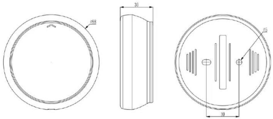
Figure 1-1 Dimension (unit: mm)
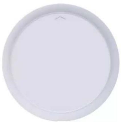
natural_image
Circular white object with a small arrow symbol on top, resembling a lid or cover (no text or symbols visible)Figure 1-2 Appearance
1.5 Cables Descripon
Refer to the table below for the cables descripon.
Table 1-2 Cables Descripon
| No. | Color | Name | Funcon |
| 1 | Red | +12 V | 12 VDC |
| 2 | Black | GND | Power ground |
| 3 | Green | RS-485A | RS-485 communicaon port |
| 4 | Blue | RS-485B | |
| 5 | Yellow | OC controlled signal | VOH/VOL controller |
| 6 | Brown | GND | Power ground |
1.6 Installaon Requirements
Install the device on the ceiling above the bed and point it to the chest of the person on the bed. The arrow on the front shell of the radar should point to the end of the bed. Aach the wires to the wall. The valid detecon range is up to 2 × 2 ~m bed. Refer to the gure below for the device installaon overview.
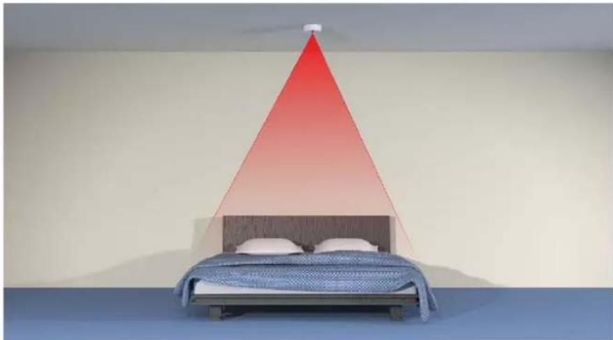
natural_image
Interior scene with a bed and a red triangular roof, no visible text or symbolsFigure 1-3 Installaon Overview
Set the device parameters and adjust the radar cover range according to the actual ceiling height.
Chapter 2 Soware Instrucon
2.1 Device Connecon
You can connect the device via Wi-Fi or RS-485. Enter the corresponding informaon according to dierent conncon modes.
2.1.1 Connection via Wi-Fi
You can connect the radar via Wi-Fi.
Before You Start
Power on the radar (12 V).
Step 1 Connect your computer to the radar AP hotspot.

Note
- SSID format: IRS60_xxxx.
● Default password: abcd1234.
Step 2 Use "ping" command to test if the computer is connected to the radar Wi-Fi.
1) Press the WIN buon and R buon at the same me.
2) Enter "cmd" and click OK.
3) Enter "ping 192.168.4.1" in the command line.
Step 3 Open the IRS60-5 Radar PC tool and click On/OFF.
Step 4 Set the network port parameters.

Note
IP address: 192.168.4.1.
- Port: 20000.
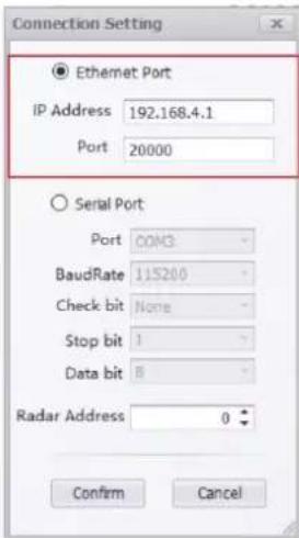
Figure 2-1 Connecon Seng
Step 5 Click Conrm.
2.1.2 Connection via RS-485
You can connect the radar via the serial port.
Step 1 Open the soware.
Step 2 Enable On/OFF.
Step 3 Select Serial Port.
Step 4 Select Port.
Step 5 Set BaudRate as 115200, Stop bit as 1, and Data bit as 8. No parity.
Step 6 Set Radar Address.

Note
Radar Address refers to the RS-485 communicaon sub-device address. 0 refers to the broadcast address that covers all the sub-device.
Step 7 Click Conrm.
2.2 Parameter Sengs
Click to open the main page. You can read the radar rmware version, edit the RS-485 sub-device address, set the radar mode, algorithm parameters, and upload mode.

Note
The parameter "00-2.10;" in algorithm parameters means that the distance from the radar to the bed is 2.1 m. Edit the value according to the actual using environment.
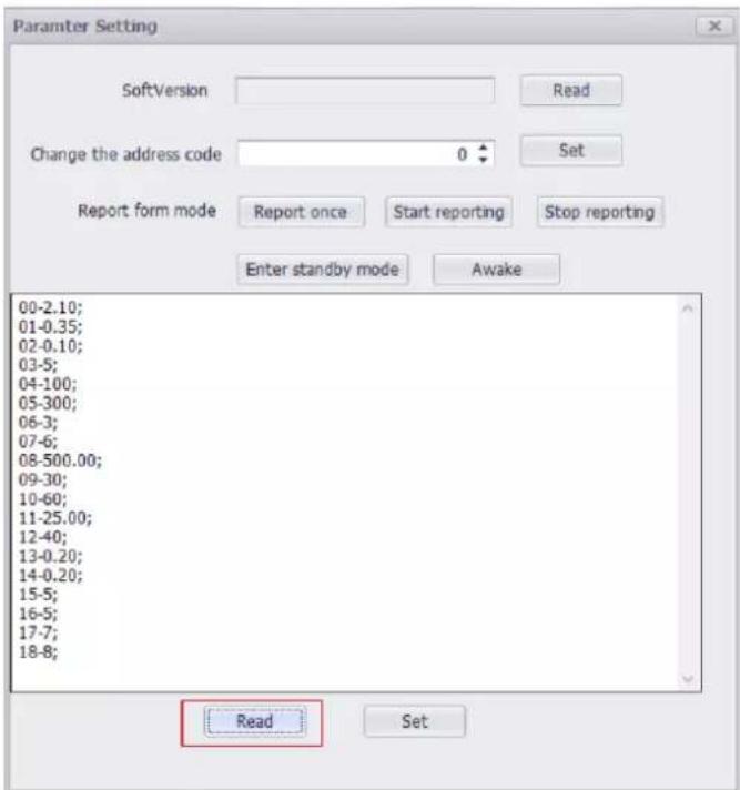
Figure 2-2 Parameter Sengs
2.2.2 Read Software Version
Click and click Read aer SoVersion to read the soware version.
2.2.3 Edit Sub-Device Address
Click ⚙, set the address code, and click Set to edit the sub-device address.

Note
The address code range is 1 to 255. Make sure the device connected address is the sub-device address or 0.
2.2.4 Select Report Mode
Click ⚙, select Report form mode, and click Set.
Start reporng
The radar will upload detecon data for every 50 ms. This mode is for single radar debugging, and you do not need to search for every me.
Stop reporng
The radar will not upload the detecon data.
Report once
The radar will only upload data once for sub-device data searching in the RS-485 network.

Note
The report mode will not be saved if the device is powered o. It will restore to the default mode aer re-powered on. The default mode varies with dierent soware version.
2.2.5 Set Radar Status
Click

set the radar status.
Enter standby mode
The radar will be standby and stop transming. If the radar is powered o and does not receive wakeup command aer powered on again, then it will sll be standby mode.
Awake
If the radar is powered o, the awake mode will be kept aer it is powered on again.
2.3 Main Page
Aer selected Report form mode as Start reporng, you can view the uploaded informaon on the main page. It includes the informaon of mes of movements, get up alarm, the me in the bed, the me out of the bed, breath rate (mes/minute), heart rate (mes/minute), mes of movements and if the human body is in the bed.
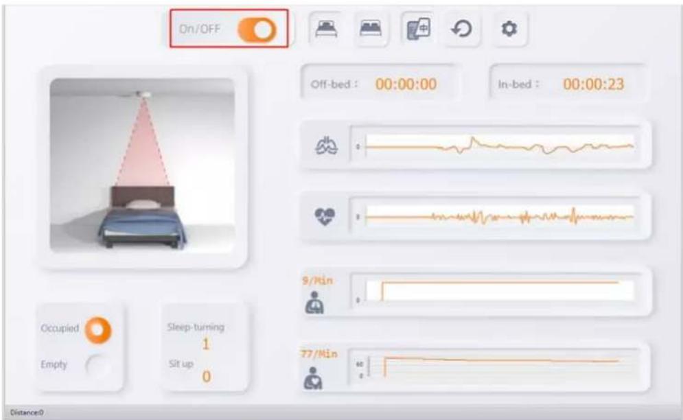
Figure 2-3 Main Page
2.4 Upgrade
You can upgrade the rmware version.
Step 1 Open the soware.
Step 2 Press F1 buon on the keyboard.
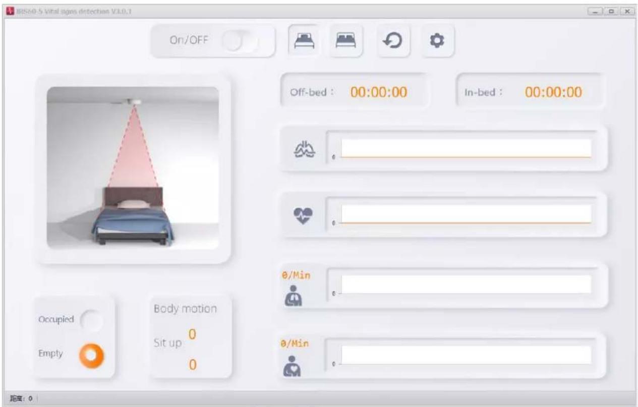
Figure 2-4 Menu Page
Step 3 Enter IP Address and Radar Port (IP address: 192.168.4.1; radar port: 6666).
Step 4 Click Connect.
Step 5 Click Browse to select the rmware to be upgraded.
Step 6 Select Network Segment as the same network segment with radar and Mode as Auto.
![Application Upgrade Radar IP 192.168.4.1 Radar Port 6666 Connect DisConnect Browse Start Update >>> Load firmware:C:\Users\admin\Desktop\total-wifi-fcd6c6a-v1.2.13\total-wifi-fcd6c6a-v1.2.13.bin [09:05:18.613] Master[v1.2.13]: hello, welcome! [09:05:18.685] version: [v1.2.13]mode: mode[30STA: ssidHROVISION SHOWROOM1.pwdHlk12345.] dhpc(0-stop,1-run): [0] ip [192.168.50.222], netmask[255.255.255.0], gw[192.16 report type(0-tcp,1-udp): [0] client: ip[192.168.50.76], [0] report interval: [0]ms radar_sn: [3004 type: [] radar hard sn: [30045525875] uart v info ok. >>> Load firmware:C:\Users\admin\Desktop\升级资料 Select an IP network segment Network Segment 192.168.4.2 Mode Auto Confirm Cancel C:\Users\admin\Desktop\升级资料\+\(^{+}\)+---\total-wifi-fcd6c6a-v1.2.13.bin Upgrade Progress 0%](/content/2026/05/1043424/images/1ee9d0381a4e8b5870badfa26dae9d97e1c5d3609ff4471701e136e8909fd685.jpg)
Figure 2-5 Applicaon Upgrade
Step 7 Click Conrm.
Step 8 Click Start Update.
![[20:39:09.774] ota status 7 [20:39:10.372] ota status 8 [20:39:11.283] ota status 9 [20:39:11.972] ota status 10 [20:39:12.641] ota status 11 [20:39:13.205] ota status 12 [20:39:13.950] ota status 13 [20:39:15.102] ota status 14 [20:39:15.698] ota status 15 [20:39:15.894] Connection closed, all data received[501409] [20:39:15.928] g_wrote_size = 501409 [20:39:16.002] total update start: adress[200000], part size[2097152], img size[501409] [20:39:16.002] update_read_buf[d6 00 01 00 00 00 00 00 00 00 00 00 00 00] [20:39:16.002] radar_bin[0],size=0, wifi_bin[1],size=501392 [20:39:19.773] ota begin, address[0x10000], size[966656], This may take time, wait... [20:39:20.741] ota status 90 [20:39:21.458] finally pack size[656], end data[... fd 39] [20:39:21.760] ota status 95 [20:39:21.938] Wifi Firmware Upgrades Successful, restart... >>>Burning successfully! D:\total-wifi-v1.2.12.bin 192.168.4.66:7777 Upgrade Progress 100% >>>Burning successfully!](/content/2026/05/1043424/images/655f93242b05792a99bcfef0a2b9dc9540396649780262a63671bc02b7178777.jpg)
Figure 2-6 Upgrade
2.5 Radar Network Conguraon
You can set the radar network.
Step 1 Open IRS60-5 Radar PC tool.
Step 2 Press F2 buon on the keyboard.
Step 3 Enter IP Address and Port (IP address: 192.168.4.1; port: 6666).
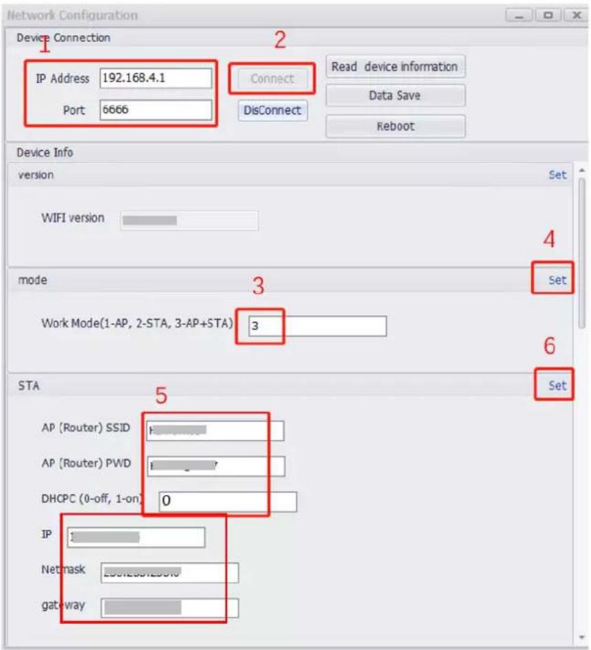
Figure 2-7 Network Conguraon
Step 4 Click Connect.
Step 5 Set Work Mode as 3.
Step 6 Click Set.
Step 7 Set AP (Router) SSID and AP (Router) PWD.

Note
AP (Router) SSID means the router name. AP (Router) PWD means the router password.
Step 8 Set DHCPC as 0 (o).
Step 9 Set IP, Netmask, and gateway.
Step 10 Click Set.
Step 11 Set AP SSID and AP PWD.

Note
AP SSID means the Wi-Fi name. AP PWD means the Wi-Fi password.
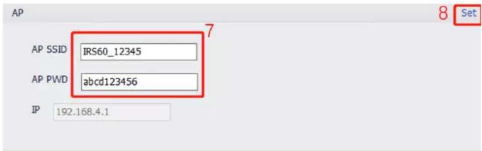
Figure 2-8 Set AP
Step 12 Click Set.
Step 13 Set Device ID as an integer (range: 1 to 999999999).
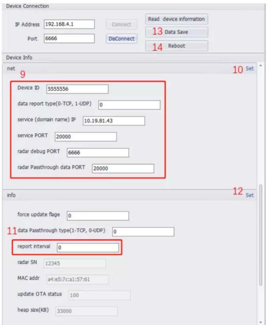
Figure 2-9 Set Device Informaon
Step 14 Set data report type as 0.
Step 15 Set service IP as Hikcentral Pro service IP.
Step 16 Set service PORT as 20000.
Step 17 Set radar debug PORT as 6666.
Step 18 Set radar Passthrough data PORT as 20000.
Step 19 Set report interval as 0.
Step 20 Click Data Save.
Step 21 Click Reboot.

See Far, Go Further
- Legal Informaon
- About this Manual
- Trademarks
- Disclaimer
- Symbol Conventions
- TABLE OF CONTENTS
- Chapter 1 Product Introducon .... 1
- Chapter 2 Soware Instrucon .... 4
- Chapter 1 Product Introducon
- Introducon
- Key Feature
- Specicaon
- Dimension and Appearance Overview
- Cables Descripon
- Installaon Requirements
- Chapter 2 Soware Instrucon
- Device Connecon
- Connection via Wi-Fi
- Before You Start
- Note
- Connection via RS-485
- Parameter Sengs
- Read Software Version
- Edit Sub-Device Address
- Select Report Mode
- Start reporng
- Stop reporng
- Report once
- Set Radar Status
- Enter standby mode
- Awake
- Main Page
- Upgrade
- Radar Network Conguraon
Brand : Hikvision
Model : DS-TDSB00-EKH
Category : Motion detector