
P.I.P.-ISO - Professional audio equipment CROWN - Free user manual and instructions
Find the device manual for free P.I.P.-ISO CROWN in PDF.


| Product Type | P.I.P. Module (Programmable Input Processor) for Crown amplifiers |
| Brand | Crown |
| Model | P.I.P.-ISO |
| Dimensions | 6 3/8 x 1 7/8 x 3 7/8 in (16.2 x 4.8 x 9.8 cm) |
| Weight | 14 oz (397 g) |
| Input Impedance | 10 kΩ nominal |
| Maximum Input Level | +20 dB at 1 kHz |
| Gain | Unity (0 dB) |
| Frequency Response | ±1 dB from 20 Hz to 15 kHz (filters flat) |
| RFI Filter | 12 dB/octave Bessel low-pass, -3 dB at 33 kHz |
| Subsonic/Bass Filter | 18 dB/octave Butterworth high-pass, selectable 50/100/300 Hz or flat |
| Common Mode Rejection | 85 dB at 1 kHz, 78 dB at 10 kHz, 68 dB at 15 kHz |
| Signal-to-Noise Ratio | Better than -90 dB (20 Hz to 20 kHz) |
| Harmonic Distortion | <0.01% THD at 0 dBm/1 kHz (any filter), <0.5% at +10 dBm/50 Hz (flat), <0.5% at +18 dBm/100 Hz (flat) |
| Crosstalk | -85 dB at 1 kHz, -82 dB at 10 kHz, -80 dB at 15 kHz |
| Maximum Source Impedance for Isolation | 600 Ω |
| Isolation (Input) | 1:1 transformers, 1 kVAC breakdown, <25 pF capacitance |
| Output Isolation | Only with ISO-modified amplifiers |
| Connectors | Quick-disconnect barrier blocks (included) |
| Compatibility | ISO-MODIFIED Com-Tech amplifiers (also Macro-Tech with separate procedure) |
| Included Accessories | ISO-MOD KIT (isolation network, keying plug, fish paper, warning sticker, instruction sheet), mounting screws, lock washers, barrier blocks, manual |
| Warranty Information | Contact Crown Technical Support for details |
Frequently Asked Questions - P.I.P.-ISO CROWN
User questions about P.I.P.-ISO CROWN
0 question about this device. Answer the ones you know or ask your own.
Ask a new question about this device
Download the instructions for your Professional audio equipment in PDF format for free! Find your manual P.I.P.-ISO - CROWN and take your electronic device back in hand. On this page are published all the documents necessary for the use of your device. P.I.P.-ISO by CROWN.
USER MANUAL P.I.P.-ISO CROWN
Applies only to North American units.
© 1997 by Crown International, Inc., P.O. Box 1000, Elkhart, Indiana 46515-1000 U.S.A. Telephone: 219-294-8000. Crown P.I.P. modules are produced by the Professional Audio Division of Crown International, Inc. Trademark Notice: Com-Tech®, Crown®, Amcron®, Macro-Tech® and P.I.P.® are registered trademarks of Crown International, Inc. Other trademarks are the property of their respective owners.
125354-1
10/97

Fig. 1.1 P.I.P.-ISO
1 Welcome
Thank you for purchasing the Crown P.I.P.-ISO accessory. P.I.P.® modules are designed to quickly install in the rear panel of many Crown amplifiers. P.I.P. stands for “Programmable Input Processor.” Their versatile features expand the capabilities of your amplifier and enable you to customize it for your particular needs.
The P.I.P.-ISO is intended for use with ISO-MODIFIED Com-Tech® series amplifiers. If it is used with an amplifier that is not iso-modified it will not have full isolation. In such a case, only the input (not the output) will be isolated from ground. The P.I.P.-ISO comes with a “ISO-MOD KIT” so a Com-Tech amplifier can be iso-modified. (These kits are also available separately.)
The amplifier modification should be performed only by a qualified technician. Once an amplifier has been iso-modified, it should not be used with any other P.I.P. modules except the P.I.P.- ISO. (It is also possible to iso-modify a Macro-Tech® series amplifier but the procedure is different. Contact the Crown Technical Support Group for more information, if required, at 219/294-8200 or 800/342-6939.)
An iso-modified amplifier with a P.I.P.-ISO has completely isolated outputs—the output voltage available between the positive and ground terminal is not referenced to earth ground. Even if either output terminal is continuously shorted to the earth ground (chassis), no damage will occur to the amplifier or any equipment interconnected to it.
The amplifier inputs are isolated by means of input transformers. The transformers are designed for 1 kVAC breakdown isolation and have less than 25 pF of primary to secondary capacitance yielding excellent common mode rejection.
In addition to isolation, the P.I.P.-ISO includes a switchable high-pass filter to attenuate unwanted
subsonics or low frequencies and a RFI (Radio Frequency Interference) filter to attenuate ultrasonic frequencies.
You should find the following items when you unpack:
P.I.P.-ISO module
Two 8-32 Phillips Machine Screws Two Lock Washers
Two Quick-Disconnect Barrier Blocks This Owner's Manual
One ISO-MOD KIT containing: One Isolation Network
One P.I.P. connector Keying Plug One piece of self-stick Fish Paper One ISO-MOD Warning Sticker ISO-MOD Instruction Sheet
1.1 Features
☐ Fail-safe output isolation allows either side of outputs to be shorted to chassis ground with no worries.
☐ EMI (Electro-Magnetic Interference) shielding provides additional gain margin under fault conditions.
☐ Balanced inputs with 1 kVAC breakdown 1:1 isolation transformers.
☐ Excellent common mode rejection.
☐ RFI filter which attenuates unwanted ultrasonic frequencies that would otherwise waste amplifier power. The RFI filter is a 12 dB/octave (2nd order), Bessel-tuned low-pass filter with a 3 dB roll-off point at 33 kHz.
☐ Switchable subsonic/bass filter with 50, 100 or 300 Hz roll-off frequencies.
☐ Quick-connect barrier block connectors provide greater wiring flexibility and make installation easier.
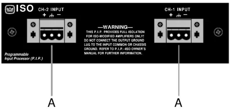
Fig. 2.1 Front View
Fig. 2.2 Bottom View

With these special quick-connect barrier-block connectors, it's quick and easy to attach each input cable with just three screws. Once the cable is attached, the connector can be quickly unplugged and, if desired, moved to a different amplifier.
B. Subsonic/Bass Switch
A 4-position sliding switch is provided for each channel to control the subsonic/bass filter. This filter is an 18 dB/octave (3rd order) Butterworth high-pass filter which can be selected to attenuate low frequencies below 50 Hz, 100 Hz or 300 Hz. It can also be switched off (Flat). A label on the side of each switch identifies the settings.
3 Installation
The P.I.P.-ISO provides input isolation with any P.I.P.-compatible amplifier but it will only provide output isolation with an amplifier that has been ISO-MODIFIED. Only a Crown-authorized service technician should attempt to modify an amplifier. Instructions for iso-modifying Com-Tech amplifiers are included in each ISO-MOD KIT.
Before installing this P.I.P. module, you'll want to adjust its subsonic/bass filters to best serve your needs.
This is easily accomplished with the four-position sliding switch located at either side of the P.I.P.-ISO (see Figure 2.2 and 2.3). The switch on the left controls the filter for Channel 2 and the switch on the right controls the filter for Channel 1. Each switch is clearly labelled (Flat, 50 Hz, 100 Hz, 300 Hz). Figure 3.1 shows the low-frequency response through the P.I.P.-ISO for each filter position.
Note: The RFI filter is always on.

line
| FREQUENCY (Hz) | FLAT (dB) | 50 Hz (dB) | 100 Hz (dB) | 300 Hz (dB) | | -------------- | --------- | ---------- | ----------- | ----------- | | 10 | 0 | -18 | -18 | -18 | | 100 | 0 | -6 | -6 | -6 | | 1K | 0 | 0 | 0 | 0 |Fig. 3.1 Subsonic/Bass Filter Settings
3.1 Installation Procedures
You may need a phillips screw-driver to remove the existing P.I.P. module or panel from your amplifier.
CAUTION: CationConnecting this or any P.I.P. to your amplifier, it is important to turn its level controls down, turn it off and remove the AC power. Don't touch the circuitry. Even though the amplifier is off, there could still be enough energy remaining to cause electric shock.
- Turn down the level controls (full counterclockwise), turn off the amplifier and unplug it from the AC power source.
- Remove the existing P.I.P. module or panel (two screws). For PIP2 amplifiers, this may
involve disconnecting the P.I.P. from a PIP2 input adapter (see Figures 3.3 and 3.4). If a PIP2 input adapter is already present, do not remove the ribbon cables from the adapter. Otherwise you will have to reconnect them in the next step.
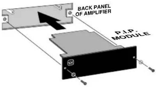
Fig. 3.2 Installation into a Standard P.I.P. Amplifier

Fig. 3.3 PIP2 Input Adapter Connection
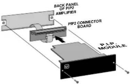
Fig. 3.4 Installation into a PIP2 Amplifier
- Standard P.I.P. Amplifiers: Align the edges of the P.I.P.-ISO in the P.I.P. card rails and firmly push the unit in until it is seated against the mounting bracket (see Figure 3.2).
PIP2 Amplifiers: (Requires a PIP2 input adaptor. Crown part number Q43528-1.) Connect the PIP2 input adapter to the two input cables of the amplifier (see Figure 3.3). Notice that the PIP2 input adapter should be positioned with the P.I.P. edge connector on top and facing away from the amplifier. The 20 pin cable (A) is connected first then the 18 pin cable (B) is connected. Both ribbon cables should extend below the PIP2 input adapter.
Next, insert the edge connector of the P.I.P.-ISO into the PIP2 input adapter (see Figure 3.4) and insert the assembly into the P.I.P. opening in the back of the amplifier.
- Secure the P.I.P.-ISO with the two screws and lock washers provided. (The lock washers are important because they bond the P.I.P. to the chassis ground of the amplifier.)
- Connect input and output wiring.
- Plug in the amplifier and turn it on. Adjust its level controls to a desired setting.
Do not tamper with the circuitry. Circuit changes made by unauthorized personnel, or unauthorized circuit modifications are not allowed.
Remember: Crown is not liable for any damage resulting from over-driving other components in your sound system.
Figure 3.5 shows how to wire a balanced and unbalanced source or daisy-chain output to the barrier block connectors.
Important: If the amplifier is used in either Bridged-Mono or Parallel-Mono mode, you must turn the Ch. 2 amplifier level control off (fully counterclockwise). The input and level control of Ch. 2 are not defeated in mono mode so any signal applied to Ch. 2 will beat against the signal in Ch. 1.
Refer to the amplifier Reference Manual for more information about Bridged-Mono or Parallel-Mono modes of operation.
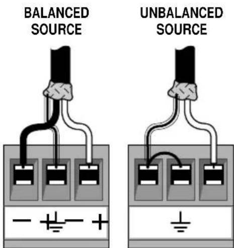
Fig. 3.5 Audio Wiring
E106377

Applies only to North American units.
4 Specifications
Note: All specifications referenced to a 0.775 V input signal.
Signal to Noise: Better than -90 dB (equivalent input noise) 20 Hz to 20 kHz.
Common Mode Rejection: 85 dB at 1 kHz; 78 dB at 10 kHz; 68 dB at 15 kHz.
Crosstalk: -85 dB at 1 kHz; -82 dB at 10 kHz; -80 dB at 15 kHz.
Harmonic Distortion: Less than 0.01% THD for 0 dBm input at 1 kHz with bass filter set to any position. Less than 0.5% THD for +10 dBm input above 50 Hz with bass filter set to flat. Less than 0.5% THD for +18 dBm input above 100 Hz with bass filter set to flat.
Input Impedance: Nominally 10 K ohm.
Maximum Source Impedance for Proper Isolation: 600 ohms.
Maximum Input Level: +20 dB at 1 kHz.
Nominal Gain: Unity.
Frequency Response: ±1 dB from 20 Hz to 15 kHz when subsonic/bass filters set flat. The subsonic/bass (high-pass) filters have selectable -3 dB roll-off points of 50, 100 or 300 Hz (see Figure 3.6) and can be switched off if desired.
A permanent RFI filter with a -3 dB roll-off at 33 kHz also affects the response.
Dimensions: 6^3 / 8 × 1^7 / 8 × 3^7 / 8 in (16.2 × 4.8 × 9.8 ~cm) .
Weight: 14 ounces (397 grams).
Brand : CROWN
Model : P.I.P.-ISO
Category : Professional audio equipment