
AC-1524 - Compressor RYOBI - Free user manual and instructions
Find the device manual for free AC-1524 RYOBI in PDF.


| Product Type | Air Compressor |
| Model | AC-1524 |
| Brand | RYOBI |
| Power Source | 120 V, 60 Hz, 15 A |
| Motor Power | 1.5 HP |
| Tank Capacity | 2.5 Gallons |
| Maximum Pressure | 150 PSI |
| Air Delivery (SCFM) | 3.0 SCFM @ 90 PSI, 4.5 SCFM @ 40 PSI |
| Dimensions (L x W x H) | 18.5 x 14.2 x 16.5 inches |
| Weight | 34.5 lbs |
| Lubrication | Oil-free pump |
| Pressure Regulation | Adjustable regulator with gauge |
| Safety Valve | Built-in ASME safety valve |
| Drain Valve | Manual drain valve for moisture removal |
| Air Outlets | 1 quick coupler, 1 universal outlet |
| Noise Level | 78 dB(A) |
| Maintenance | Drain tank daily; clean intake filter monthly; inspect for leaks |
| Safety Features | Thermal overload protector, automatic shut-off |
| Spare Parts Availability | Filters, valves, and regulators available through RYOBI service centers |
| Repair Information | Refer to authorized service center for pump or motor repairs |
Frequently Asked Questions - AC-1524 RYOBI
User questions about AC-1524 RYOBI
0 question about this device. Answer the ones you know or ask your own.
Ask a new question about this device
Download the instructions for your Compressor in PDF format for free! Find your manual AC-1524 - RYOBI and take your electronic device back in hand. On this page are published all the documents necessary for the use of your device. AC-1524 by RYOBI.
USER MANUAL AC-1524 RYOBI
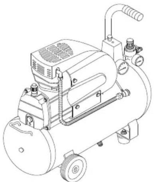
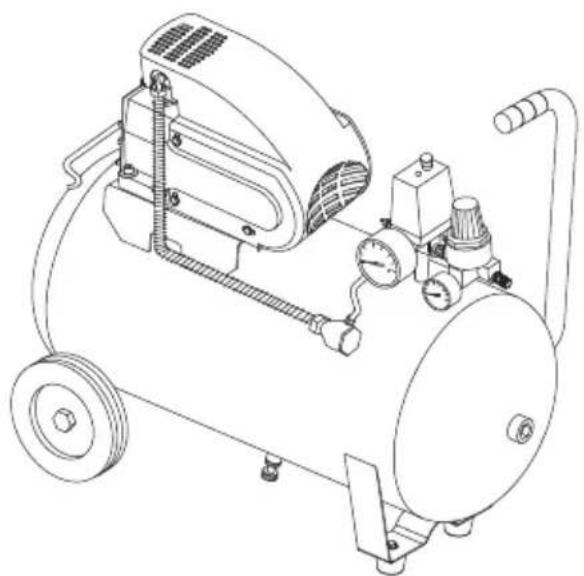
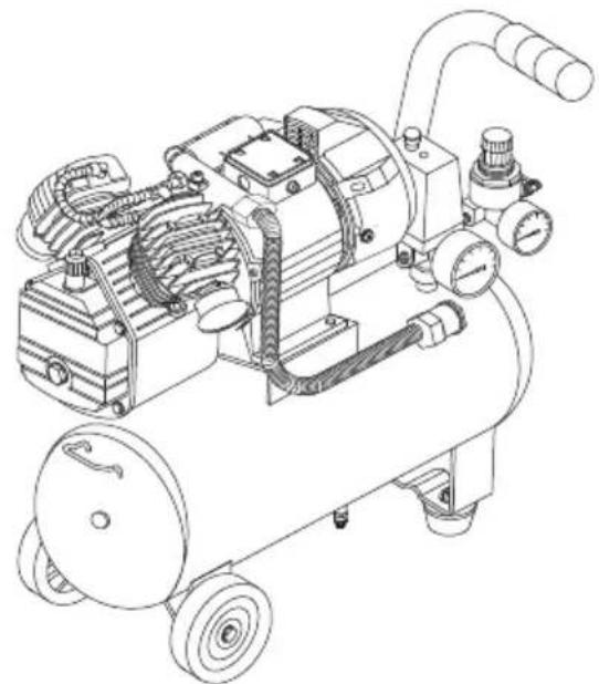
AC-1524, AC-2050, AC-2055K, AC-3050
OWNER'S OPERATING MANUAL
natural_image
Line drawing of an air compressor with pressure gauge and wheels (no text or symbols)AC-1524
natural_image
Technical line drawing of an air compressor with pressure gauges and wheels (no text or symbols)AC-2050/AC-2055K
natural_image
Technical line drawing of an air compressor with hoses and control panel (no text or labels)AC-3050
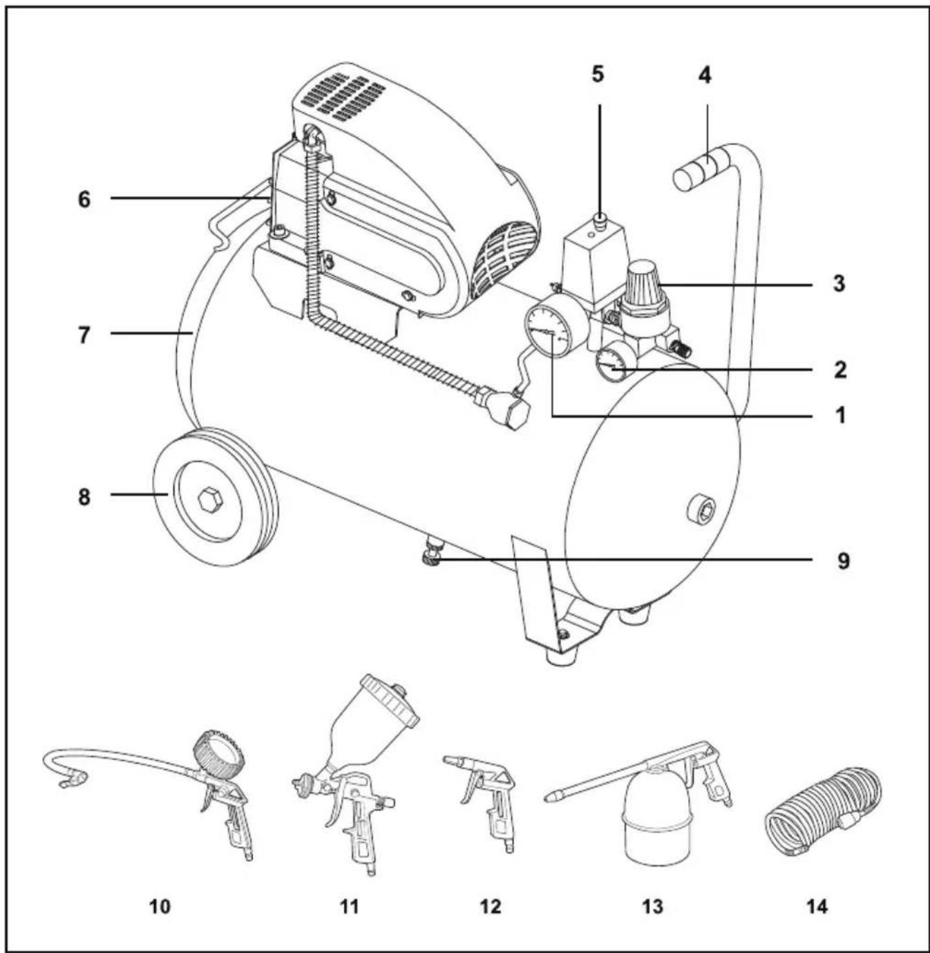
DESCRIPTION
- Pressure gauge (pressure in tank)
- Pressure gauge (using pressure)
- Regulator
- Handle
-
Pressure switch
-
Oil silght glass
- Tank
- Wheel
- Drain valve
ACCESSORIES (For AC-2055K only):
- Air tyre inflator
- Gravity powered paint spray gun
-
Air duster gun
-
Engine cleaning gun
- Air recoil hose
GENERAL SAFETY RULES
- KEEP WORK AREA CLEAN AND DRY. Cluttered, damp, or wet work areas invite injuries.
■ KEEP CHILDREN AWAY FROM WORK AREA. Do not allow children to handle this product. - KEEP IDLE EQUIPMENT. When not in use, tools and equipment should be kept in a dry location to inhibit rust. Always lock up tools and equipment, and keep out of reach of children.
■ DO NOT USE THIS PRODUCT IF UNDER THE INFLUENCE OF ALCOHOL OR DRUGS. Read warning labels on prescriptions to determine if your judgement or reflexes are impaired while taking drugs. If there is any doubt, do not attempt to use this product.
■ USE EYE AND HAND PROTECTION. Wear safety impact goggles and heavy-duty work gloves when using this product.
■ DRESS SAFELY. Do not wear loose clothing or jewelry, as they can become caught in moving parts. Wear a protective hair covering to prevent long hair from becoming caught in moving parts. If wearing a long-sleeve shirt, roll sleeves up above elbows.
■ DO NOT OVER REACH. Keep proper footing and balance at all times to prevent tripping, falling, back injury, etcetera.
■ STAY ALERT. Watch what you are doing at all times. Use common sense. Do not use this product when you are tired or distracted from the job at hand.
■ CHECK FOR DAMAGED PARTS. Before using this product, carefully check that it will operate properly and perform its intended function. Check for damaged parts and any other conditions that may affect the operation of this product. Replace or repair damaged or worn parts immediately.
■ REPLACEMENT PARTS AND ACCESSORIES: When servicing, use only identical replacement parts. Only use accessories intended for use with this product.
■ MAINTANTAIN THIS PRODUCT WITH CARE. Keep this product clean and dry for better and safer performance.
■ MAINTENANCE: For your safety, service and maintenance should be performed regularly by a qualified technician.
■ USE THE RIGHT TOOL FOR THE JOB. Do not attempt to force a small tool or attachment to do the work of a larger industrial tool. There are certain applications for which this tool was designed. It will do the job better and more safely at the rate for which it was intended. Do not modify this tool, and do not use this tool for a purpose for which it was not intended.

WARNING: The warnings, precautions, and instructions discussed in this manual cannot cover all possible conditions and situations that may occur. The operator must understand that common sense and caution are factors, which cannot be built into this product, but must be supplied by the operator.
SPECIFIC PRODUCT WARNINGS AND PRECAUTIONS

WARNING: Make sure to fill the Air Compressor with a premium quality, non-detergent compressor oil before each use. Running the Air Compressor with no oil or low oil will cause damage to the equipment.
■ MAKE SURE ALL TOOLS AND EQUIPMENT USED WITH THE AIR COMPRESSOR ARE RATED TO THE APPROPRIATATE CAPACITY. Do not use any tool or equipment that does not operate from 0 to 115 PSI.
■ Do not leave compressor unattended for an extended period while plugged in. Unplug compressor after working.
■ Keep compressor well-ventilated. Do not cover
compressor during use.
■ DRAIN AIR COMPRESSOR EVERY DAY. Do not allow moisture to build up inside the Air Compressor.
■ MAINTANTAIN A SAFE WORKING ENVIRONMENT. Keep the work area well lit. Make sure there is adequate surrounding workspace. Always keep the work area free of obstructions, grease, oil, trash, and other debris. Do not use the Air Compressor in areas near flammable chemicals, dusts, and vapors.
■ AVOID INJURY: Never direct the Air Flow Valve at people or animals.
■ DO NOT ALTER OR REMOVE THE FACTORY SEALED PRESSURE RELEASE VALVE.
GENERAL SAFETY RULES
■ DO NOT OPEN THE WATER DRAIN VALVE SO THAT MORE THAN FOUR THREADS ARE SHOWING.
■ An extension cord must NEVER be used with this item. Connecting this item to an outlet through an extension cord may cause electrical damage to the motor and could present a fire hazard.
■ THIS COMPRESSOR MAY REQUIRE A DEDICATED ELECTRICAL CIRCUIT AS THE AMPERAGE DRAW UNDER FULL LOAD COMBINED WITH USE OF ANY OTHER ITEM MAY OVERLOAD YOUR CIRCUIT.

WARNING: People with pacemakers should consult their physician(s) before using this product. Operation of electrical equipment in close proximity to a heart pacemaker could cause interference to or failure of the pacemaker.

RISK OF MOVING PARTS
If the air compressor is in operation, all guards and covers should be attached or installed correctly. If any guard or cover has been damaged, do not operate the equipment until the proper personnel has correctly repaired the equipment. The power cord should be free of any moving parts, twisting and/or crimping while in use and while in storage.

RISK OF BURNS
There are surfaces on your air compressor that while in operation and thereafter can cause serious burns if touched. The equipment should be allowed time to cool before any maintenance is attempted. Items such as the compressor pump and the outlet tube are normally hot during and after operation.

RISK OF FALLING
Operation of the air compressor should always be in a position that is stable. Never use the air compressor on a rooftop or elevated position that could allow the unit to fall or be tipped over. Use additional air hose for elevated jobs.

RISK FROM FLYING OBJECTS
Always wear safety glasses with side shields when the air compressor is in use. Turn off the air compressor and drain the air tank before performing any type of maintenance or disassembly of the hoses or fittings. Never point any nozzle or sprayer toward any part of the body or at other people or animals.

RISK OF BREATHING
Avoid using the air compressor in confined areas. Always have adequate space(300mm) on all sides of the air compressor. Also keep children, pets, and others out of the area of operation. This air compressor does not provide breathable air for anyone or any auxiliary breathing device. Spraying material will always need to be in another area away from the air compressor to not allow intake air to damage the air compressor filter.

RISK OF ELECTRICAL SHOCK
Never utilize the air compressor in the rain or wet conditions. Any electrical issues or repairs should be performed by authorized personnel such as an electrician and should comply with all national and local electrical codes. The air compressor should also have the proper three prong grounding plug, correct voltage, and adequate fuse protection.

RISK OF EXPLOSION OR FIRE
Never operate the compressor near combustible materials, gasoline or solvent vapors. If spraying flammable materials, locate the air compressor at least 20 feet away from the spray area. Never operate the air compressor indoors or in a confined area.

RISK OF BURSTING
Always drain the air compressor tank daily or after each use. If the tank develops a leak, then replace the air compressor. Never use the air compressor after a leak has been found or try to make any modifications to the tank. Never modify the air compressor's factory settings which control the tank pressure or any other function.
SPECIFICATIONS
| AC-1524 | AC-2050/AC-2055K | AC-3050 | |
| Voltage | 230V ~50Hz | 230V ~50Hz | 230V ~50Hz |
| Power input | 1.1KW 1.5HP | 1.5KW 2.0HP | 2.2KW 3HP |
| Tank capacity | 24L | 50L | 50L |
| Air displacement capacity | 150L/min | 190L/min | 350L/min |
| Pump capacity | 8Bar/115psi | 8Bar/115psi | 8Bar/115psi |
| No load speed | 2800r/min | 2800r/min | 2800r/min |
| Nett weight | 22.5kg | 32.5kg | 39.5kg |
THINGS YOU SHOULD KNOW
■ All the compressors are fitted with a safety valve that is tripped in the case of malfunctioning of the pressure switch in order to assure machine safety.
■ When fitting a tool, the flow of air in output must be switched off.
■ When using compressed air, you must know and comply with the safety precautions to be adopted for each type of application (inflation,
pneumatic tools, painting, washing with water-based detergents only, etc.).
START-UP AND USE
■ Fit the wheels and foot on.
■ Screw on the air filter. (fig.1)
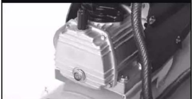
■ Check the oil level using sight glass, and if necessary top up. (fig.2)
■ Check for correspondence between the compressor plate data with the actual specifications of the electrical system. A variation of ± 10% in respect to the rated value is allowed.
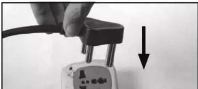
■ Insert the plug of the power cable in a suitable socket, checking that the button of the pressure switch located on the compressor is in the OFF position. (fig.3)
natural_image
Close-up of a hand holding a black plug with two metal pins, next to a white electrical socket with a black arrow pointing downward (no text or symbols visible)Fig. 3

natural_image
Close-up of a hand holding a black mechanical component with a threaded rod (no visible text or symbols)Fig. 1
natural_image
Close-up of a mechanical component with metallic housing and wiring (no visible text or symbols)Fig. 2
START-UP AND USE
■ At this point, the compressor is ready for use.
■ Pull up the pressure switch, the compressor starts, pumping air into the receiver through the delivery pipe. (fig.4)
■ When the upper calibration value (set by the manufacturer) has been reached, the compressor stops, venting the excess air present in the head and in the delivery pipe through a valve located under the pressure switch. This facilitates subsequent restart due to the absence of pressure in the head. When air is used, the compressor restarts automatically when the lower calibration value is reached (2 bar between upper and lower).
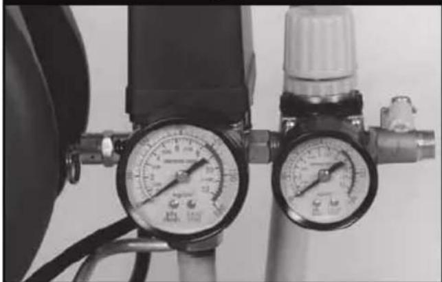
■ The pressure in the receiver can be checked on the gauge provided (fig. 5).
■ The compressor continues to operate according to this automatic cycle until the switch of the output pipe is turned off.
■ Always wait at least 10 seconds from when the compressor has been switched off before restarting this.
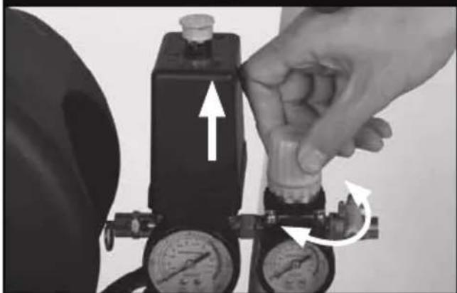
■ All compressors are fitted with a pressure regulator. Operating the knob with the tap open, turn the regulator in a clockwise direction to increase the pressure and in a counterclockwise direction to reduce this (fig. 6), air pressure can be regulated so as to optimize use of pneumatic tools. After setting the value required, the ring-nut underneath must be tightened to fasten the knob (fig.7).
■ The value set can be checked on the gauge.
■ Please check that the air consumption and the maximum working pressure of the pneumatic tool to be used are compatible with the pressure set on the pressure regulator and with the amount of air supplied by the compressor.
■ Always pull out the plug and drain the receiver once you have completed your work (fig.8).

natural_image
Hand holding a white plastic pipe attached to a wall-mounted device (no text or symbols visible)Fig. 8

natural_image
Close-up of a hand holding a black object with an upward arrow and downward arrow indicating motion (no text or symbols)Fig. 4
natural_image
Close-up of two pressure gauges with attached tubing, no visible text or symbolsFig. 5
natural_image
Close-up of a hand adjusting a pressure regulator with directional arrows indicating movement (no text or symbols visible)Fig. 6

natural_image
Close-up of a hand adjusting a pressure regulator with two gauges and a valve, no visible text or symbols.Fig. 7
MAINTENANCE
■ BEFORE CARRYING OUT ANY OPERATION, ALWAYS PULL OUT THE PLUG AND DRAIN THE RECEIVER COMPLETELY
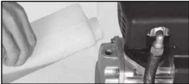
■ Replace the oil after the first 100 hours of operation and every 300 hours subsequently (fig.9). Remember to check the oil level at regular intervals.
■ Periodically (or after working with the compressor for more than an hour), drain the condensate that forms inside the receiver (fig. 8) due to the humidity in the air. This protects the receiver from corrosion and does not restrict its capacity.
■ Spent oil and condensate MUST BE DISPOSED OF in accordance with environmental protection regulations and current legislation.
■ The compressor must be disposed in conformity with the methods provided for by local regulations.
natural_image
Close-up of a hand pouring liquid into a plastic bottle, next to a mechanical component with a coiled hose (no visible text or symbols)Fig. 9
natural_image
Close-up of a hand using a wrench to adjust or install an engine component on a white surface (no visible text or symbols)Fig. 10
| TABLE 1 - MAINTENANCE | |||
| FUNCTION | AFTER THE FIRST 100 HOURS | EVERY 100 HOURS | EVERY 300 HOURS |
| Cleaning of intake filter and/or substitution of filtering element | ● | ||
| Change of oil | ● | ● | |
| Tightening of head tension rods | At start-up and after the first hour of work | ||
| Draining tank condensate | Periodically and at the end of work | ||

natural_image
Close-up of a hand adjusting a mechanical component with a tool, no visible text or symbolsFig. 11
POSSIBLE FAULTS AND RELATED PERMITTED REMEDIES
| FAULT | CAUSE | REMEDY |
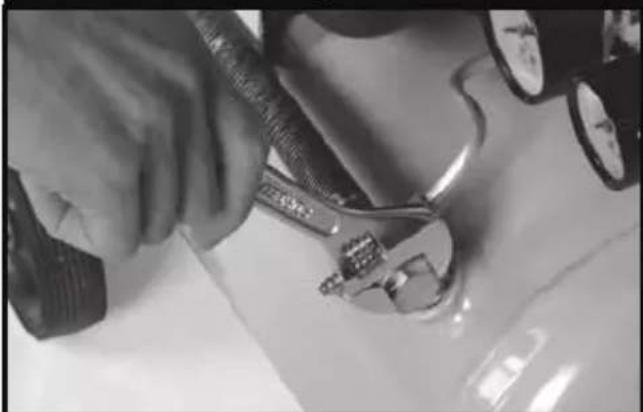
| Leakage of air from the valve of the pressure switch with the compressor off. | Check valve that, due to wear or dirt on the seal, does not perform its function correctly. | Unscrew the hexagonal head of the check valve, clean the valve seat and the special rubber disk (replace if worn). Reassemble and tighten carefully (figures 10-11). |
| Reduction of performance. Frequent start-up. Low pressure values. | Excessive performance request, check for any leaks from the couplings and/or pipes. Intake filter may be clogged. | Replace the seals of the fitting, clean or replace the filter. |
| The compressor stops and restarts automatically after a few minutes. In the V, 3 HP versions, it is does not start. | Tripping of the thermal cutout due to overheating of the motor. | Clean the air ducts in the conveyor. Ventilate the work area. Reset the thermal cutout. On lubricated and V type models, check oil level and quality. On V models, have the voltage checked. |
| After a few attempts to restart, the compressor. | Tripping of the thermal cutout due to overheating of the motor (removal of the plug with the compressor running, low power voltage). | Activate the on/off switch. Ventilate the work area. Wait a few minutes. The compressor will restart independently. On V, 3 HP models, reset the thermal cutout. Remove any power cable extensions. |
| The compressor does not stop and the safety valve is tripped. | Irregular functioning of the compressor or breakage of the pressure switch. | Remove the plug and contact the Service Center. |
RYOBI POWER EQUIPMENT WARRANTY
Subject to the warranty conditions below, this RYOBI tool (hereinafter called "the Product"), is warranted by Ryobi (herein called "the Company") to be free from defects in material or workmanship for a period of 24 months from the date of original purchase covering both parts and labour. Under the terms of this warranty, the repair or replacement of any part shall be the opinion of the Company or its authorised agent. Should service become necessary during the warranty period, the owner should contact the authorised Ryobi retailer from whom the product was purchased, or the nearest Company branch office. In order to obtain warranty service, the owner must include the Sales Docket and Warranty Certificate to confirm date of purchase. This Product is sold by the dealer or agent as principal and the dealer has no authority from the Company to give any additional warranty or guarantee on the Company's behalf except as herein contained or herein referred to.
Warranty Conditions
This warranty only applies provided that the Product has been used in accordance with the manufacturer's recommendations under normal use and reasonable care (in the opinion of the Company) and such warranty does not cover consumable components, damage, malfunction or failure resulting from misuse, neglect, abuse, or used for a purpose for which it was not designed, or is not suited and no repairs, alterations or modifications have been attempted by other than an Authorised Service Agent. This guarantee will not apply if the tool is damaged by accident or if repairs arise from normal wear and tear.
Accessories such as bits, blades, sanding discs, cutting lines, etc., are excluded from this guarantee. Normal consumable parts, such as carbon brushes, bearings, chucks, cord assembly's, spark plugs, recoil pulleys and bump head assembly's are specifically excluded from this guarantee.
The Company accepts no additional liability pursuant to this warranty for the costs of traveling or transportation of the Product or parts to and from the sevice dealer or agent - which costs are not included in the warranty.
Nothing herein shall have the effect of excluding, restricting or modifying any conditions, warranty, right or liability imposed, to the extent only that such exclusion, restriction or modification would render any term herein void.
RYOBI®
STEVENS & CO (Pty) Ltd
604, 16th Street, Randjespark
Midrand, South Africa
P O Box 4059
HALFWAY HOUSE
1685, South Africa
Tel: +27 (11) 357-9600
Fax: +27 (11) 805-5541
email: stevens@ryobi.co.za
THIS WARRANTY FORM
SHOULD BE RETAINED BY THE CUSTOMER AT ALL TIMES.
For your record and to assist in establishing date of purchase (necessary for in-warranty service), please keep your purchase docket and this form, completed with the following particulars.
PURCHASED FROM:
ADDRESS OF DEALER:
DATE:...... MODEL NO
SERIAL NO.
Present this form with your Purchase Docket when Warranty Service is required.




- AC-1524, AC-2050, AC-2055K, AC-3050
- DESCRIPTION
- ACCESSORIES (For AC-2055K only):
- GENERAL SAFETY RULES
- SPECIFIC PRODUCT WARNINGS AND PRECAUTIONS
- RISK OF MOVING PARTS
- RISK OF BURNS
- RISK OF FALLING
- RISK FROM FLYING OBJECTS
- RISK OF BREATHING
- RISK OF ELECTRICAL SHOCK
- RISK OF EXPLOSION OR FIRE
- RISK OF BURSTING
- SPECIFICATIONS
- THINGS YOU SHOULD KNOW
- START-UP AND USE
- MAINTENANCE
- RYOBI POWER EQUIPMENT WARRANTY
- Warranty Conditions
Brand : RYOBI
Model : AC-1524
Category : Compressor