
VMCS-101 - Grill plate Vulcan - Free user manual and instructions
Find the device manual for free VMCS-101 Vulcan in PDF.

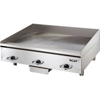
| Product type | Professional griddle plate |
| Brand | Vulcan |
| Model | VMCS-101 |
| Dimensions (W x D x H) | 800 x 700 x 300 mm |
| Weight | 45 kg |
| Fuel | Gas (propane/butane) or natural gas |
| Power | 12 kW |
| Cooking surface | Chrome steel, dimensions 700 x 450 mm |
| Thermostat | Adjustable from 50°C to 300°C |
| Main functions | Grilling, searing, keep warm |
| Grease collector | Removable tray located at the front |
| Maintenance | Regular cleaning of the plate and grease tray |
| Cleaning | Removable plate for dishwasher cleaning (manual recommended) |
| Safety | Safety thermocouple, automatic shut-off in case of flameout |
| Ignition | Integrated piezoelectric |
| Material | Stainless steel for the structure |
| Adjustable feet | Yes, for leveling |
| Gas connection | 1/2" BSP, hose included |
| Spare parts available | Cooking plate, thermocouple, valves, etc. |
| Repairability | Repairability score 8/10 (according to manufacturer data) |
| Warranty | 2 years parts and labor |
| Certifications | CE, NF, gas compliance |
Frequently Asked Questions - VMCS-101 Vulcan
User questions about VMCS-101 Vulcan
0 question about this device. Answer the ones you know or ask your own.
Ask a new question about this device
Download the instructions for your Grill plate in PDF format for free! Find your manual VMCS-101 - Vulcan and take your electronic device back in hand. On this page are published all the documents necessary for the use of your device. VMCS-101 by Vulcan.
USER MANUAL VMCS-101 Vulcan
OPERATION AND FIELD INSTALLATION MANUAL VMCS Heavy Duty Electric Griddle Top
MODELS
VMCS-101
VMCS-102
VMCS-201
VMCS-202
natural_image
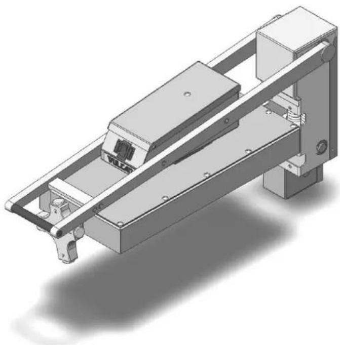
3D technical illustration of a mechanical assembly with mounting brackets and internal components (no text or symbols)VMCS-101
For additional information on Vulcan or to locate an authorized parts and service provider in your area, visit our website at www.vulcanequipment.com
TABLE OF CONTENTS
OPERATIONS
Installation....3
Electrical specifications....3
Controls....5
Raising/lowering griddle top....6
Teflon wrap installation....6
Plate gap adjuster....7
Using the griddle....8
Care and cleaning....8
Shutdown....9
Maintenance....10
FIELD INSTALLATION ASSEMBLY
Tools required....10
Mounting bracket assembly....11
Mounting bracket installation....11
Griddle top installation....14
Mounting plate installation....14
Bumper stop installation....17
Range of motion....17
Electrical connections and specifications....18
Wiring diagram....19
Troubleshooting....20
VMCS HEAVY DUTY ELECTRIC GRIDDLE TOP
GENERAL
VMCS Heavy Duty Electric Griddle Tops are produced with quality workmanship and materials. Proper installation, usage and maintenance of the griddle top will result in many years of satisfactory performance.
Thoroughly read this entire manual before beginning and carefully follow all of the instructions provided.
INSTALLATION
Before installing, check the electrical service to make sure it agrees with the specifications on the rating plate. If the supply and equipment voltages do not agree, do not proceed with the installation. Contact your dealer or Vulcan-Hart immediately.
INSTALLATION CODES AND STANDARDS
Your Vulcan griddle top must be installed in accordance with:
In the United States of America:
- State and local codes
- National Electrical Code ANSI/NFPA – 70 (latest edition) available from The National Fire Protection Association,1 Batterymarch Park,Quincy, MA 02269.
- NFPA Standard #96 Vapor Removal from Cooking Equipment, (latest edition) available From the National Fire Protection Association, Batterymarch Park, Quincy, MA 02269.
In Canada:
- Local code
- Canadian Electrical Code C22.1 Part 1 (latest edition) available from the Canadian Standard Association, 5060 Spectrum Way, Suite 100, Mississauga, Ontario, Canada, L4W 5N6.
| ELECTRICAL SPECIFICATIONS | ||||
| Model No | Description | Voltage | Power | 1 Phase Draw |
| VMCS-101 | FLAT | 208V | 3.6 KW | 17.3 A |
| VMCS-102 | PLATE | 240V | 15.0 A | |
| VMCS-201 | GROOVED | 208V | 17.3 A | |
| VMCS-202 | PLATE | 240V | 15.0 A | |
UNPACKING
This griddle top was inspected before leaving the factory. The carrier assumes full responsibility for the safe delivery upon acceptance of the shipment. Check for possible shipping damage immediately after receipt.
If the griddle top is found to be damaged, complete the following steps:
- Carrier must be notified within 5 business days of receipt.
- Carrier's local terminal must be notified immediately upon discovery (note time, date, and who was spoken to), and follow up and confirm with written or electronic communication.
- All original packing materials must be kept for inspection purposes.
- The griddle top cannot have been moved, installed, or modified.
- Notify Vulcan Customer Service immediately at 800-814-2028.
Check that the following have been included:
- Bumper stop assembly(see page 16)
○ (4) Bumper stop assembly mounting screws
• (2) Mounting plates (see page 14)
○ (4) M10 mounting plate screws
○ (4) M10 mounting plate lock washers
- Teflon sheet kit (see page 6)
○ (2) Teflon sheets
○ (2) Teflon clips
- Teflon bracket
The VMCS mounting bracket (see page 11) is a separate accessory and shipped in another package. It is recommended that you specify factory mounting of the bracket if you are purchasing a new griddle with the VMCS Heavy Duty Electric Griddle Top.
WARNING
The griddle and its parts are hot. Use care when operating, cleaning or briddle.
WARNING
Disconnect power supply and follow lockout / tagout procedures and servicing the appliance.
BEFORE FIRST USE
Remove all packaging material and protective plastic from the unit. It is recommended that you clean your Vulcan VMCS griddle top thoroughly with a mild soap and water. Wipe the griddle surface thoroughly with water and wipe dry with a soft clean cloth.
Each time, before turning the unit on, apply high temperature cooking oil – about two ounces per VMCS top plate. Work the oil into the whole griddle surface.
After cleaning your griddle with chemicals, you should repeat the seasoning procedure for proper cooking.
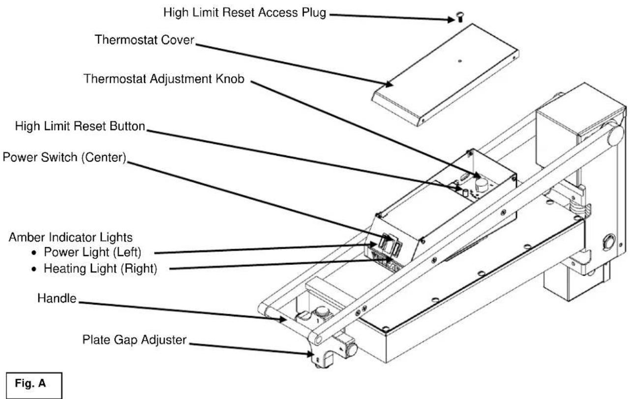
CONTROLS
The heavy duty electric griddle top section is independently controlled by a power switch, thermostat and high limit cutoff switch. When the power switch (red rocker switch) is turned ON, the left amber light will illuminate and power will be supplied to the thermostat. The thermostat cover must be removed to access the thermostat adjustment knob.
When the thermostat is turned ON, the amber indicator light to the right of the power switch will illuminate to indicate that the element is on. When the griddle plate reaches the desired temperature set point, the element will be turned off and the amber indicator light will go off. The high limit cutoff switch is a safety feature that will cut power to the heating element to prevent overheating. The high limit switch can be reset by depressing the high limit reset button. At the end of each day, you must push the power switch to the OFF position to turn off power to the griddle top section. See Fig. A.
natural_image
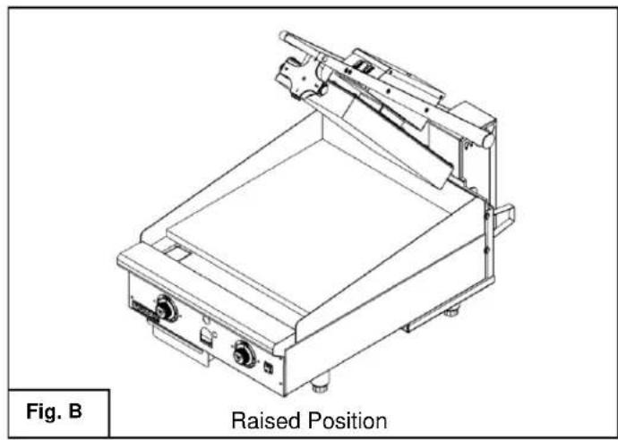
Technical line drawing of a mechanical device with raised position label (no other text or symbols)To raise the assembly
- Lift by the handle only
- Hold handle until assembly holds in place at the approximate 53° position. Fig. B
⚠ WARNING Always hold handle to maintain control of the unit until lifting mechanism holds in the desired raised position or rests in the lowered position. Do not allow unit to swing upward or downward under its own power as this may result in injury or equipment damage.
natural_image
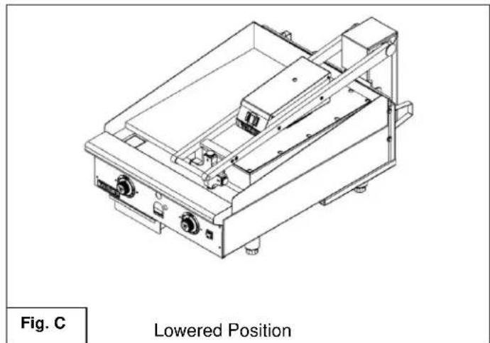
Technical line drawing of a mechanical device with no visible text or symbolsTo lower the assembly
- Grasp the handle and pull downward. Continue to hold handle until the unit stops in lowered position. Fig. C
NOTICE Do not force unit if it does not move up and down in the prescribed manner. The assembly may be damaged by the application of excessive upward or downward force. Contact an authorized service contractor if assembly becomes difficult to move.
TEFLON WRAP INSTALLATION
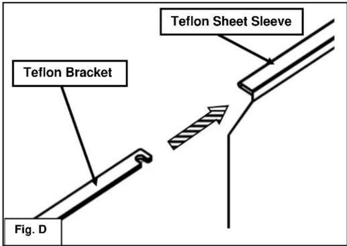
WARNING The griddle and its parts are hot. Use care when operating, cleaning or servicing the griddle.
- Clean off platen using soft cloth, water and mild soap solution.
- Slide the Teflon bracket (#944503) into the sleeve of the Teflon sheet as shown in Fig. D.
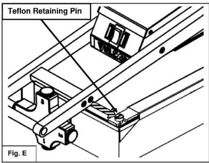
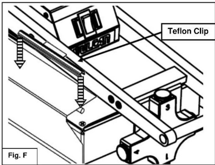
PLATE GAP ADJUSTER
- Raise the platen to the 53° raised position. Drape the Teflon sheet from the right side of the platen by hooking the front and back of the Teflon bracket to the Teflon retaining pins. See Fig. E.
- Pull the Teflon sheet from the right side around the face of the platen cooking surface to the left side.
- Pull the Teflon sheet tight and ensure the cooking surface of the platen is completely covered by the Teflon sheet.
- Secure the Teflon sheet to the left side of the platen with the two Teflon clips. Push the clips down over the Teflon sheet, clipping onto the round rods underneath the sheet. See Fig. F.
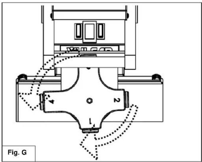
The plate gap adjuster is used to prevent soft foods from being crushed by the downward force of the unit. The "1" setting would be used for the smallest or no gap with "4" being used to create the largest gap.
Settings are changed by rotating the gap adjuster body to the left or right until it locks in place at the desired setpoint.
USING THE VMCS ELECTRIC GRIDDLE TOP
To preheat, wipe the griddle top plate with cooking oil and set the thermostats for the desired temperatures 10-12 minutes before cooking.
A uniform and systematic approach to loading the griddle will produce the most consistent product results.
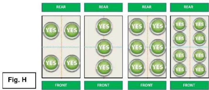
flowchart
graph TD
    A["REAR"] --> B["FRONT"]
    B --> C["FRONT"]
    C --> D["FRONT"]
    D --> E["FRONT"]
    E --> F["FRONT"]
    style A fill:#f9f,stroke:#333
    style B fill:#ccf,stroke:#333
    style C fill:#cfc,stroke:#333
    style D fill:#fcc,stroke:#333
    style E fill:#cff,stroke:#333
    style F fill:#ffc,stroke:#333
The flat cooking surface units feature the Rapid Recovery™ plate which is a composite material with a stainless steel surface. The grooved cooking surface units have plates composed of standard, carbon steel. Both cooking surfaces can be scored or dented by careless use of a spatula or scraper. Be careful not to dent, scratch, or gouge the plate surface. Do not try to knock off loose food that may be on the spatula by tapping the corner or the edge of the spatula on the griddle surface. Do not use hardened steel spatulas. Use mild steel spatulas with rounded corners.
CARE AND CLEANING
WARNING The griddle and its parts are hot. Use care when operating, cleaning or servicing the griddle.
Clean the electric griddle top regularly. A clean griddle always looks better, lasts longer and performs better. To produce evenly cooked, perfectly browned griddle products keep the griddle plate clean and free of carbonized grease. Carbonized grease on the surface hinders the transfer of heat from the griddle surface to the food, resulting in spotty browning and loss of cooking efficiency. Carbonized grease tends to cling to griddle foods, giving them a highly unsatisfactory and unappetizing appearance.
To keep the griddle clean and operating at peak efficiency, follow these procedures:
AFTER EACH USE
Clean the electric griddle top with a griddle scraper during the work shift. Keep the griddle scraper head flat to avoid scratching or gouging the plate. Use a cooking release agent to prevent product from sticking to the griddle top cooking surface.
ONCE PER DAY
Thoroughly clean all stainless steel exterior panels and surfaces. Clean the cooking surface with a non-metallic scouring pad (Scotch-Brite™).
ONCE PER WEEK
Clean the griddle surface thoroughly. A mild detergent solution may be used on the plate surface to help clean it, but be sure the detergent is thoroughly removed by wiping down with clear water. After removal of detergent from the surface of the plate, the griddle should be coated with cooking oil according to the instructions in this manual. Clean stainless steel surfaces with a damp cloth and polish with a soft dry cloth. To remove discoloration, use a griddle cleaner. If the griddle usage is very high, consider conducting this weekly cleaning procedure more than once per week.
Do not use a brick or griddle stone for cleaning.
Do not use metallic scouring pads for cleaning.
Do not use a water-jet to clean the griddle.
Do not use chlorine sanitizer in contact with griddle. Contact can cause discoloration, corrosion and permanent damage.
Do not use cleaning agents including Sodium Hydroxide, which is common in household oven cleaners. Contact can cause discoloration, corrosion and permanent damage.
CARE AND CLEANING OF TEFLON WRAP
- In between cooking runs and during idle periods, the Teflon sheet should be wiped off with water and a clean soft cloth.
- After each day the Teflon sheet should be removed from the platen(s), disassembled and placed in water with mild soap solution (no abrasive or harsh chemical cleaners should be used). Gently wash both sides of the Teflon sheet and the hardware with the soft clean cloth in the mild soap solution.
- Using water, rinse the Teflon sheet and hardware thoroughly on both sides.
- Dry the Teflon sheet and hardware using a clean soft cloth.
- Before reassembling the Teflon sheet to the platen, clean the platen as described in Care and Cleaning section.
SHUTDOWN OF GRIDDLE
- Set the power switch to the OFF position. This will shut down the griddle top completely.
- Leave unit in the raised, 53^ position.
EXTENDED SHUTDOWN
- Set the power switch to the OFF position. This will shut down the griddle top completely.
- Leave unit in the raised, 53° position.
- Apply a light coating of cooking oil on the grooved (steel) plate to inhibit rust.
- Shut off the main electrical supply
MAINTENANCE
WARNING The griddle and its parts are hot. Use care when operating, cleaning or servicing the griddle.
WARNING Disconnect power supply and follow lockout / tagout procedures before cleaning and servicing the appliance.
LUBRICATION
There are no parts on this unit that require lubrication.
SERVICE AND PARTS INFORMATION
Contact the Authorized Service Contractor in your area to obtain service and parts information. For a complete listing of Service and Parts depots refer to www.vulcanequipment.com.
When calling for service the following information should be available from the appliance serial plate: Model Number, Serial Number and voltage.
FIELD INSTALLATION ASSEMBLY
Contact the authorized service contractor in your area for field installation.
The field installation instructions are prepared for the use of trained service technicians and should only be used by those who are properly qualified. These instructions are not intended to be all encompassing. You should read, in its entirety, the installation instructions to determine if you have the necessary tools, instruments and skills required to perform the procedure. The field installation should not be attempted if you do not have the necessary tools, instruments and skills.
TOOLS REQUIRED FOR FIELD INSTALLATION
-
2 Philips head screw driver
- M10 socket driver
- 7/16" socket driver
- Rubber mallet
- Power drill
- 7/8" deep well socket wrench
- (2) large "F" clamps
- 5/32" drill bits for metal
- Thread lock compound (Loctite Blue®)
- 34 " wide masking tape
BRACKET ASSEMBLY AND INSTALLATION
WARNING The griddle and its parts are hot. Use care when operating, cleaning or servicing the griddle.
WARNING Disconnect power supply and follow lockout / tagout procedures before cleaning and servicing the appliance.
Prior to assembly, make sure the mounting bracket is the correct size. The back bracket should match the width of the griddle. Make sure the griddle top electrical specifications match the available service. Each griddle top will require its own separate electrical service.
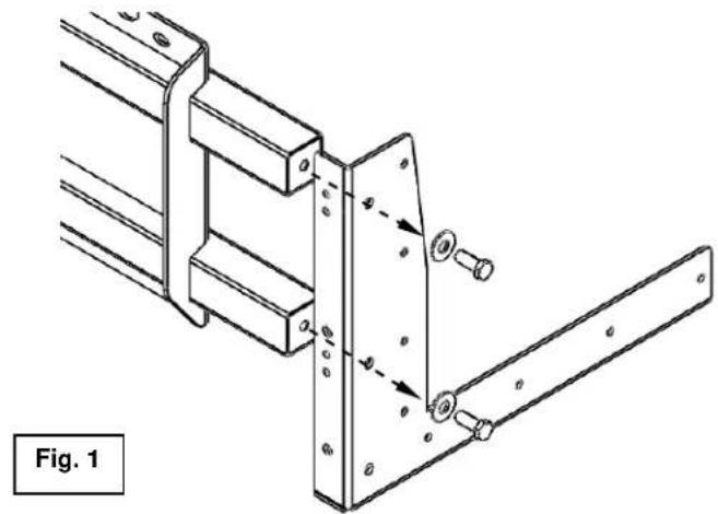
- Using (2) washers and (2) 14 "-28 bolts, assemble one of the side mount brackets to the back bracket as shown in Fig. 1. The bolts should be hand tightened only at this point. Repeat procedure to attach the other side mount bracket to the other end of the back bracket.
- The entire mounting bracket system should be assembled at this point as shown in Fig. 2 with bolts hand tightened only.
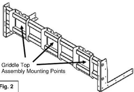
Fig. 2
natural_image
Industrial metal frame with pipes and bolts, labeled as Fig. 3 (no readable text or symbols)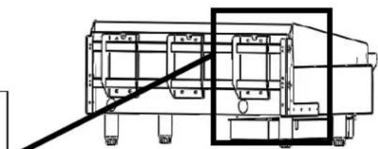
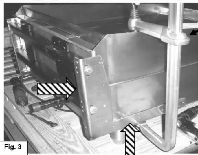
natural_image
Technical line drawing of a mechanical assembly with no visible text or symbols- Slide mounting bracket system onto back of the griddle as shown in Fig. 3. The left and right side brackets should be pushed up until stopped by the bottom of the griddle and pushed forward until stopped by the griddle back panel. Secure the mounting bracket system at this location with a "F" clamp on each side of the assembly as shown. Place a wood block or other type of protection between clamp and griddle plate.
-
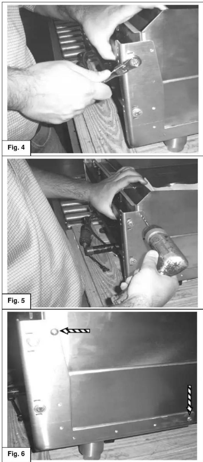
Securely tighten the mounting bracket system assembly bolts at the left and right side mounting brackets. Fig. 4.
-
Check that the left and right mounting brackets have not moved from position while the assembly bolts were tightened. The "F" clamps should still be in place to prevent the assembly from moving while drilling holes in the chassis.
Check before drilling holes in chassis, it is important that the assembly has not moved from the location prescribed in step # 3
-
Using the side mounting bracket as a guide, drill holes into the griddle chassis with the 5/32" bits only at the highest hole and the hole nearest the front of the unit on the side bracket. See Fig. 5 and Fig 6. Repeat procedure for opposite side of bracket system assembly.
-
Insert and tighten 10-24 x ½ screws into the holes that were drilled in step 6. Repeat procedure for opposite side of bracket system assembly. See Fig. 6.
natural_image
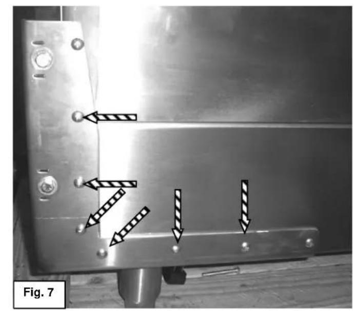
Metallic mechanical component with bolt holes and directional arrows indicating movement or force (no text or symbols)-
Drill the remaining holes through the side mounting brackets into the griddle chassis. Insert and tighten screws as shown in Fig. 7. Repeat procedure for the other side of the assembly.
-
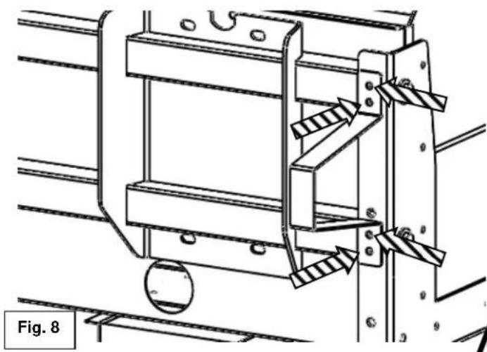
Drill holes with 5/32" bits from the rear of the side mounting bracket into the back mounting bracket and install wall spacer with (4) 10-24 x ½" screws as shown in Fig. 8. Repeat procedure for the other side of the assembly.
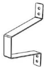
Wall Spacer
natural_image
Technical line drawing of a mechanical assembly with no visible text or symbols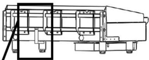
natural_image
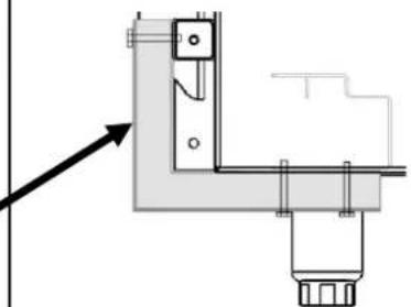
Technical line drawing of a mechanical device with no visible text or symbols- Install one bottom support bracket every two feet of griddle width between griddle top mounting points as needed for additional support. Bottom support brackets should be flush with bottom of griddle chassis and back mounting bracket. Drill two holes with 5/32" bits and attach with 10-24 x 2" screws as shown in Fig.9 to the back mounting bracket. Repeat for each bottom support bracket needed.
natural_image
Technical line drawing of a corner junction fixture with mounting bracket and support structure (no text or symbols)Cutaway side view
Fig. 9
natural_image
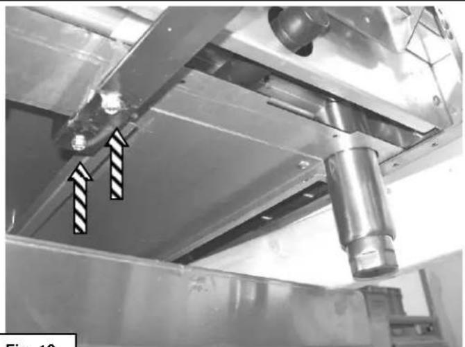
Industrial equipment component with metallic beams and a cylindrical shaft, showing two arrows pointing to features (no text or symbols visible)Fig. 10
A WARNING It may be necessary to
angle the griddle and hang one of the four legs off the edge of the table at a time to complete step 11. Ensure that the griddle is safely supported and this step is accomplished with aid of a second person.
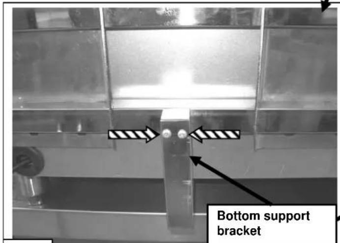
- Drill two holes with 5/32" bits through bottom support brackets and into the bottom of griddle chassis. Insert and tighten 10-24 x 2" screws as shown in Fig.10. Repeat as necessary for all bottom support brackets.
GRIDDLE TOP INSTALLATION
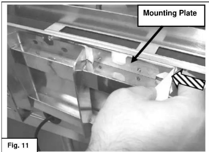
- Attach masking tape to mounting plate and slide into position between the griddle back panel and the top of the selected griddle top mounting point as shown in Fig. 11.
natural_image
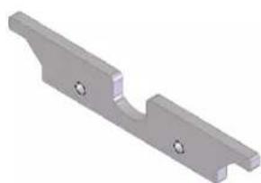
3D rendered image of a metallic mechanical bracket with two mounting holes (no text or symbols)Mounting Plate
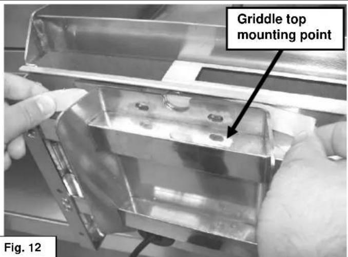
- Use tape to align holes in mounting plate with holes in griddle top mounting point as shown in Fig. 12. Tape to hold in position until installation of griddle top is complete. Repeat steps 12 and 13 for the bottom mounting point.
natural_image
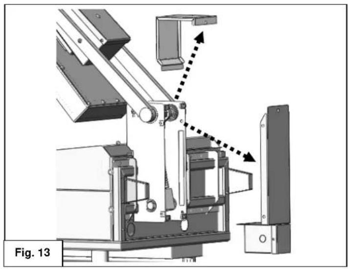
Mechanical assembly diagram showing a robotic arm with motion arrows, labeled Fig. 13 (no text or symbols on the diagram itself)- Place cardboard or other protective covering on the gas griddle surface to prevent scratching.
WARNING Ensure that the unit is safely supported and steps 15 through 20 are accomplished with aid of a second person.
- Remove top and rear spring armature covers. Set into place in the raised position. Fig. 13.
natural_image
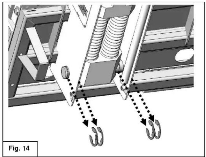
Mechanical assembly diagram showing spring and hook components with dotted arrows indicating motion (no text or symbols)- Remove the four retaining clips that secure the lower pivot rod. Fig 14.
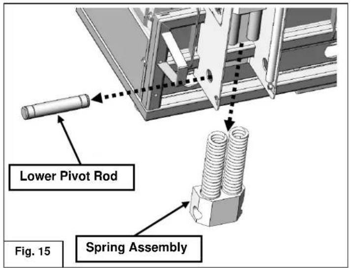
- Remove the lower pivot rod, then remove the spring assembly as shown in Fig 15.
natural_image
Technical diagram of a mechanical assembly with labeled components and alignment lines (no readable text or symbols)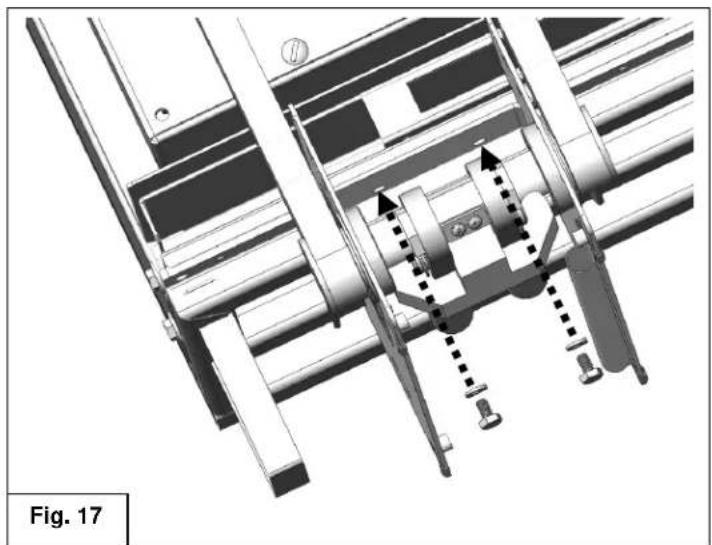
natural_image
Technical diagram of a mechanical assembly with no visible text or symbols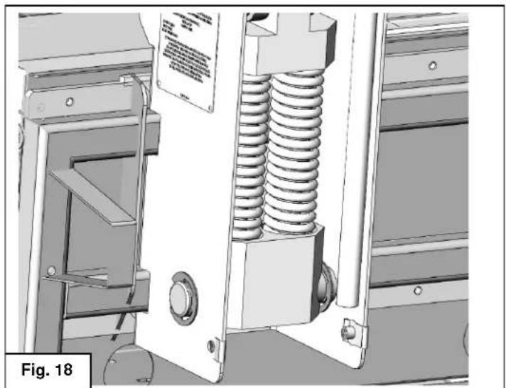
natural_image
Technical illustration of a mechanical assembly with spring and housing components (no visible text or symbols)WARNING Ensure that the unit is safely supported and steps 15 through 20 are accomplished with aid of a second person.
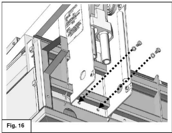
NOTICE Apply a thread locking compound to the mounting bracket screws in steps 18 and 19.
- Insert and tighten the bottom mounting bracket screws and washers. Fig.16.
Ensure the mounting screws fully engage the mounting plate that is referenced in steps 12 and 13.
- Set unit to lowered position as shown in Fig C on page 6. Insert and tighten the top mounting bracket screws and washers. Fig.17.
Ensure the mounting screws fully engage the mounting plate that is referenced in steps 12 and 13.
Recheck and tighten bottom mounting screws as necessary.
- Reverse steps 16 and 17 to reinstall the spring assembly, lower pivot rod and four retaining clips. Fig.18
natural_image
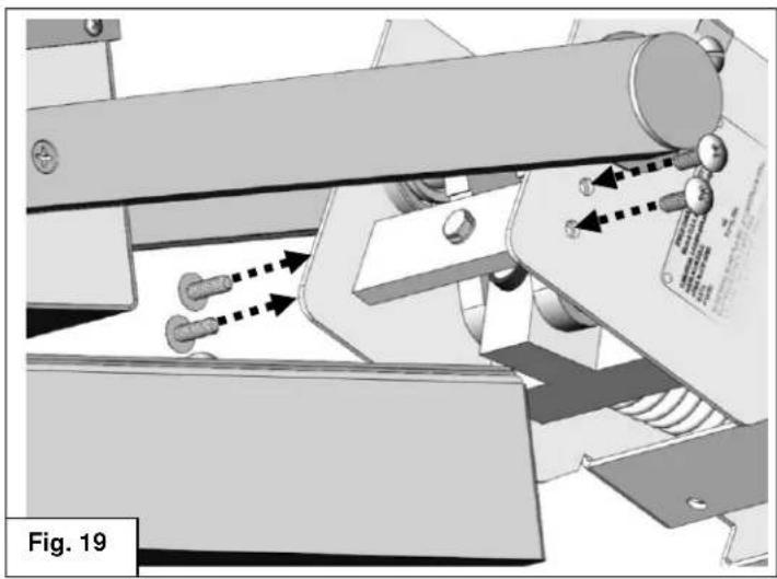
Mechanical assembly diagram showing a conveyor belt system with directional arrows indicating motion (no text or symbols present)- Install the bumper stop assembly into top of armature. Fig. 19
natural_image
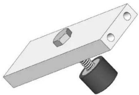
3D illustration of a mechanical clamp with a bolt and spring (no text or symbols)Bumper Stop Assembly
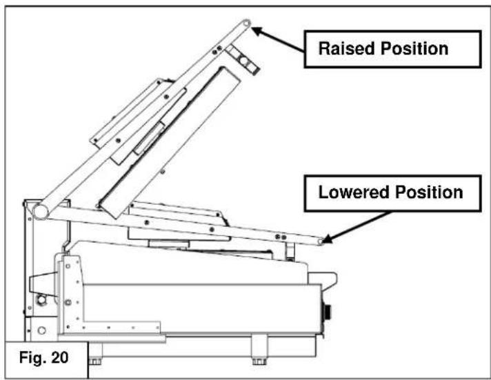
- Check range of motion as shown in Fig. 20. The assembly should hold in place at the raised, 53° position and rest under its own weight in the lowered position. Refer to page 6 for proper raising and lowering technique.
natural_image
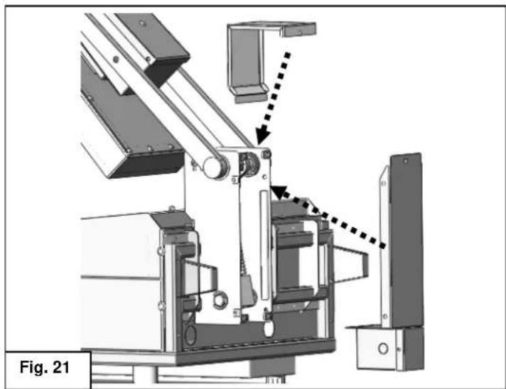
Mechanical assembly diagram showing a robotic arm with motion arrows and labeled Fig. 21 (no text or symbols on the diagram itself)-
Reinstall the top and rear spring armature covers. Fig. 21
-
Repeat proceeding steps as needed for each griddle top head assembly.
ELECTRICAL CONNECTIONS
⚠ WARNING Electrical and grounding connections must comply with the applicable portions of the National Electrical Code and/or other local electrical codes.
⚠ WARNING Disconnect the electrical power to the griddle and follow lockout / tagout procedures.
Since the griddle top is not fused, you must connect to a fused circuit equipped with a suitable disconnecting means as required by local authorities.
Electrical Connections
- Remove the small junction box cover plate on the back of the unit. This exposes the VMCS clamshell griddle line leads.
- Select a suitable knockout on the sides or bottom of the junction box.
- Connect the griddle's line leads to the supply wires with factory supplied wire connectors as shown in the applicable wiring diagrams.
- Push the excess wire into the junction box and replace the cover plate. Never operate griddle without cover in place.
| ELECTRICAL SPECIFICATIONS | ||||
| Model No | Description | Voltage | Power | 1 Phase Draw |
| VMCS-101 | FLAT | 208V | 3.6 KW | 17.3 A |
| VMCS-102 | PLATE | 240V | 15.0 A | |
| VMCS-201 | GROOVED | 208V | 17.3 A | |
| VMCS-202 | PLATE | 240V | 15.0 A | |
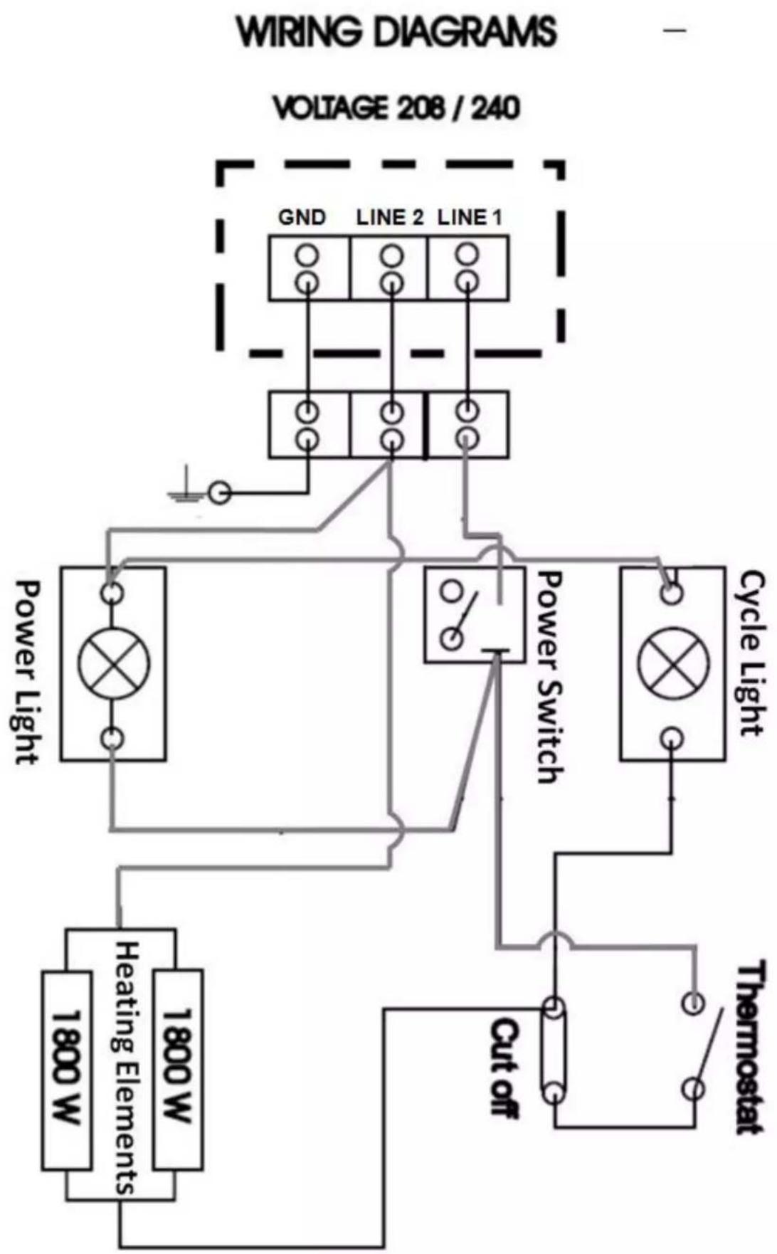
flowchart
graph TD
    A["Power Light"] --> B["Heating Elements"]
    A --> C["1800 W"]
    A --> D["1800 W"]
    E["Cycle Light"] --> F["Cycle Light"]
    G["VOLTAGE 208 / 240"] --> H["GND LINE 2 LINE 1"]
    I["Power Switch"] --> J["Switch"]
    K["Cut off"] --> L["Thermostat"]
    M["Line 2"] --> N["Line 1"]
    O["Line 1"] --> P["Line 2"]
TROUBLESHOOTING
natural_image
3D rendering of a mechanical assembly with a spring and hex nut, labeled 'Ensemble du butor' (no other text or symbols)natural_image
Technical illustration of a mechanical assembly with spring and housing (no visible text or symbols)natural_image
Technical diagram of a mechanical assembly with no visible text or symbolsnatural_image
Metal mechanical bracket component with two mounting holes (no text or symbols)natural_image
Industrial machine component with metal parts and a cylindrical component, showing no visible text or symbols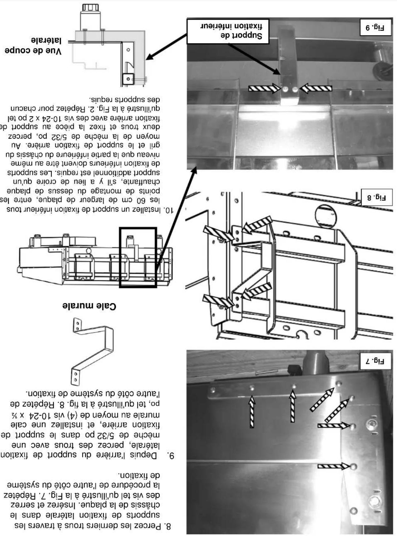
natural_image
Close-up of hands operating a mechanical tool with a drill bit, no visible text or symbols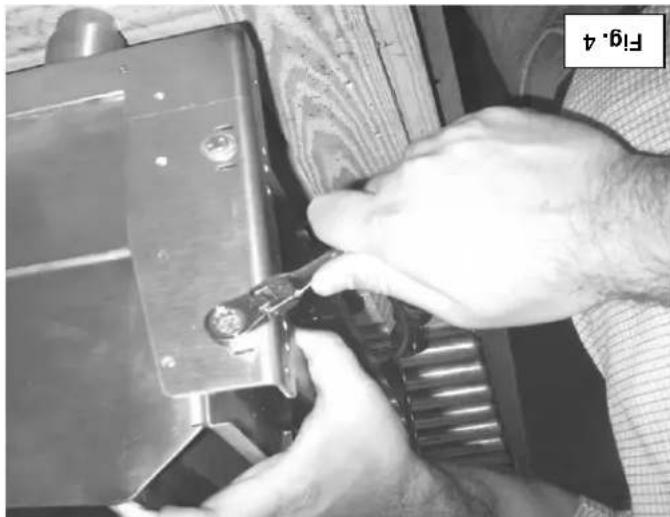
natural_image
Close-up of hands using a tool to adjust or install a mechanical component (no visible text or symbols)natural_image
Industrial metal frame with structural components and safety markings (no readable text or symbols)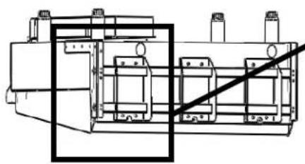
natural_image
Technical line drawing of a mechanical assembly with no visible text or symbolsFig.2
plaque chauffante
-
Cile a doubles 7/16 po
-
Cite a doubles M10
OUTILS REQUIIS POUR L'INSTALLATIONI. TOURNEYS CRUCIFORME n° 2
competences requires, Installation ne devrait jamsis etre tentee.
Park, Quincy, MA 02269.
edition), disponible auprès de la National Fire Protection Association, Batterymarch
- Norme no 96 de NFPA, Vapor Removal from Cooking Equipment, (plus recente
National Fire Protection Association, 1 Batterymarch Park, Quincy, MA 02269.
les directives fournies.
performance satisfaction.
natural_image
3D technical illustration of a mechanical assembly with mounting brackets and mounting holes (no text or symbols)VMCS-202
VMCS-201
VMCS-102
VMCS-101
MODELES
Desssus De Plaque Chauffante Electrique De Fabrication Robuste VMC5
MANUEL D'UTILISATION ET D'INSTALLATION
- OPERATION AND FIELD INSTALLATION MANUAL VMCS Heavy Duty Electric Griddle Top
- TABLE OF CONTENTS
- OPERATIONS
- FIELD INSTALLATION ASSEMBLY
- VMCS HEAVY DUTY ELECTRIC GRIDDLE TOP
- GENERAL
- INSTALLATION
- INSTALLATION CODES AND STANDARDS
- UNPACKING
- WARNING
- BEFORE FIRST USE
- CONTROLS
- USING THE VMCS ELECTRIC GRIDDLE TOP
- CARE AND CLEANING
- AFTER EACH USE
- ONCE PER DAY
- ONCE PER WEEK
- CARE AND CLEANING OF TEFLON WRAP
- SHUTDOWN OF GRIDDLE
- EXTENDED SHUTDOWN
- MAINTENANCE
- LUBRICATION
- SERVICE AND PARTS INFORMATION
- TOOLS REQUIRED FOR FIELD INSTALLATION
- Philips head screw driver
- BRACKET ASSEMBLY AND INSTALLATION
- A WARNING It may be necessary to
- GRIDDLE TOP INSTALLATION
- ELECTRICAL CONNECTIONS
- OUTILS REQUIIS POUR L'INSTALLATIONI. TOURNEYS CRUCIFORME n° 2
- Desssus De Plaque Chauffante Electrique De Fabrication Robuste VMC5
Brand : Vulcan
Model : VMCS-101
Category : Grill plate