SFE50 - Coffee maker Giesen Coffee Roasters - Free user manual and instructions
Find the device manual for free SFE50 Giesen Coffee Roasters in PDF.

| Product Type | Coffee Roaster |
| Brand | Giesen Coffee Roasters |
| Model | SFE50 |
| Dimensions (W x D x H) | 800 x 600 x 800 mm |
| Weight | 80 kg |
| Power Supply | 230V / 50Hz, 3.5 kW |
| Batch Capacity | 50 kg (green coffee) |
| Roasting Method | Drum roasting |
| Control System | Programmable touchscreen with profiling |
| Cooling System | Integrated cooling tray with fan |
| Heating Type | Gas or electric (depending on configuration) |
| Material | Stainless steel drum and body |
| Chaff Collection | Built-in chaff collection system |
| Safety Features | Overheat protection, emergency stop, smoke detection |
| Maintenance | Daily cleaning of cooling tray and chaff collector; periodic drum brush |
| Spare Parts Availability | Common parts (drum, thermocouples, bearings) available from Giesen dealers |
| Warranty | 2 years (components and workmanship) |
| Noise Level | < 75 dB(A) |
Frequently Asked Questions - SFE50 Giesen Coffee Roasters
User questions about SFE50 Giesen Coffee Roasters
0 question about this device. Answer the ones you know or ask your own.
Ask a new question about this device
Download the instructions for your Coffee maker in PDF format for free! Find your manual SFE50 - Giesen Coffee Roasters and take your electronic device back in hand. On this page are published all the documents necessary for the use of your device. SFE50 by Giesen Coffee Roasters.
USER MANUAL SFE50 Giesen Coffee Roasters
Please read this manual carefully before using. Retain the manual for further future reference.
natural_image
White industrial electrical enclosure with open door and control panel (no visible text or symbols)TABLE OF CONTENTS
1.0 Manufacturer 3
2.0 Introduction......4
3.0 Safety instructions and warnings 5
3.1 General....5
3.2 User manual 5
3.3 Pictograms and instructions on the product ..... 5
3.4 Users....5
3.5 Intended use 5
3.6 Safety features 6
3.7 General use 6
3.8 Use of SFE/HFE for welding fume extraction...... 6
3.9 Use of SFE for commercial kitchen extraction ..... 7
4.0 Service, maintenance and repairs 8
5.0 Technical specifications 9
6.0 General description.... 10
6.1 SFE and HFE for welding fume extraction 10
6.2 SFE in kitchen extraction applications.... 10
6.3 Oil drainer.... 10
6.4 Operation.... 10
7.0 Installation 11
7.1 Installation SFE 11
7.2 Installation HFE 11
8.0 Maintenance.... 12
8.1 Periodic maintenance 12
8.2 Cleaning the separate parts 12
9.0 Troubleshooting.... 14
10.0 Images.... 16
1.0 MANUFACTURER
The manufacturer of the Giesen SFE Filter is Giesen Coffee Roasters B.V. located in The Netherlands.
Address:
Giesen Coffee Roasters
Industrieweg 13-15
7071 CK Ulft
The Netherlands
Contact:
Telephone support: +31 (0)315 74 50 55
E-mail support: support@giesen.eu
Telephone service / sales: +31 (0)315 68 13 77
E-mail service / sales: info@giesen.eu
Copyright:
Copyright © 2020 by Giesen Coffee Roasters
All rights reserved. No part of this publication may be reproduced, distributed, or transmitted in any form or by any means, including photocopying, recording, or other electronic or mechanical methods, without the prior written permission of the publisher. For permission requests, write to the publisher, addressed "Attention: Manual" at the address above.
Giesen Coffee Roasters is constantly improving its products and reserves the right to change these without prior notice. This manual contains general information and is not part of the contract. Although this manual has been compiled with the utmost care, it may contain incomplete information or inaccuracies. Giesen Coffee Roasters, therefore, disclaims all liability. Giesen Coffee Roasters advises its users at all times to consult on the use of its coffee roaster and accessories. This manual applies to the type or types of machines indicated on the front cover. These instructions meet the requirements as laid down in the applicable European directive as stated on the declaration of conformity. If there are any questions or comments, please contact Giesen Coffee Roasters. The machine can only be started when the complete manual has been read and understood. Any responsibility for damage or injury resulting from non-compliance with the instructions as described in this manual, or non-observance of normal and generally accepted caution and care during installation, operation, maintenance or repairs, even if not expressly stated, will be rejected by the manufacturer.
2.0 INTRODUCTION
This manual is intended to be used as a work of reference for professional, well trained and authorised users to be able to safely install, use, maintain and repair the product mentioned on the cover of this document. The figures referred to in the text, can be found in the back of this manual.
For information about specific adjustments, maintenance or repair jobs which are not dealt with in this manual, please contact the supplier of the product. He will always be willing to help you. Make sure you have the following specifications at hand:
- product name
- serial number
These data can be found on the identification plate. The manufacturer does not accept any liability for damage to the product or personal injury caused by non-observance of the safety instructions in this manual, or by negligence during installation, use, maintenance and repair of the product mentioned on the cover of this document and any corresponding accessories.
3.0 SAFETY INSTRUCTIONS AND WARNINGS
3.1 GENERAL
The manufacturer does not accept any liability for damage to the product or personal injury caused by non-observance of the safety instructions in this manual, or by negligence during installation, use, maintenance and repair of the product mentioned on the cover of this document and any corresponding accessories. Specific working conditions or used accessories may require additional safety instructions. Immediately contact your supplier if you detect a potential danger when using the product.
The user of the product is always fully responsible for observing the local safety instructions and regulations. Observe all applicable safety instructions and regulations.
3.2 USER MANUAL
- Everyone working on or with the product, must be familiar with the contents of this manual and must strictly observe the instructions therein. The management should instruct the personnel in accordance with the manual and observe all instructions and directions given.
• Never change the order of the steps to perform.
• Always keep the manual with the product.
3.3 PICTOGRAMS AND INSTRUCTIONS ON THE PRODUCT
- The pictograms, warnings and instructions attached to the product are part of the safety features. They must not be covered or removed and must be present and legible during the entire life of the product.
- Immediately replace or repair damaged or illegible pictograms, warnings and instructions.
3.4 USERS
The use of this product is exclusively reserved to authorized, trained and qualified users. Temporary personnel and trainees can only use the product under supervision and responsibility of skilled engineers.
3.5 INTENDED USE
The product has been designed exclusively for extracting and/or filtering harmful fumes and gasses which are released during the most common welding processes and for use in commercial kitchens. Using the product for other purposes is considered contrary to its intended use. The manufacturer accepts no liability for any damage or injury resulting from such use.
The product has been built in accordance with state-of-the-art standards and recognised safety regulations. Only use the product in technically perfect condition with its intended use and the instructions laid down in the user manual.
3.6 SAFETY FEATURES
- All safety features must be correctly mounted and can only be removed for maintenance and repair jobs by skilled and authorised service engineers.
- The product must not be used if the safety features are not or only partly present, or defective.
- The safety features should be regularly checked for their proper functioning, and if required, be immediately repaired.
3.7 GENERAL USE
WARNING: Fire hazard! Never use the product for extracting and/or filtering inflammable, glowing or burning particles or solids or liquids. Never use the product for extracting and/or filtering of aggressive fumes (such as hydrochloric acid) or sharp particles.
- Inspect the product and check it for damage. Verify the functioning of the safety features.
- Check the working environment. Do not allow unauthorized persons to enter the working environment.
- Use common sense. Stay alert and pay attention to your work. Do not use the product when you are tired or under the influence of drugs, alcohol or medicine.
- Make sure the room is always sufficiently ventilated, particularly in smaller confined areas.
- Never install the product in front of entrances and exits which must be used by emergency services.
• Make sure that the workshop contains sufficient approved fire extinguishers. - Protect the product against water and humidity.
- Do not use the product at a relative humidity exceeding 80%.
- Do not use the product at temperatures below 5°C or above 45°C.
- Keep the operating controls free from dirt and grease.
- The product is not explosion-proof rated. The motor can cause sparks and should therefore not be used in areas with an explosion risk.
• Never operate the product without filters. - Do not use the product in areas with high concentrations of dry particulates (dust).
3.8 USE OF SFE/HFE FOR WELDING FUME EXTRACTION
- The product is suitable for the extraction/filtration of fumes and gasses from or during the following welding processes:
- MIG/MAG solid wire (GMAW)
- MIG/MAG flux cored wire (FCAW)
- stick welding (MMA or SMAW)
- TIG (GTAW) welding
- autogeneous welding
-
oil mists
-
Health-threatening particles in the air, such as chromium, nickel, beryllium, cadmium, lead, etc., shall not be recycled. The extracted air shall be directed outside the operating area.
- Never use the product for extracting dust particles which are released when welding surfaces treated with primer.
- Never use the product for extracting and/or filtering fumes and gases which are released during the following (welding) processes:
- arc-air gouging
- paint mist
- hot gasses (more than 40°C continuously)
- aggressive fumes (such as acid fumes)
- plasma cutting
- grindings of aluminium or magnesium
- flame cutting
- cement, saw dust or woodcuttings, etc.
- burning cigarettes, cigars, oiled tissues and other flammable or burning particles, objects and acids
- under all explosive circumstances |
(This list is not a limited list)
- The use of this product in areas with heavy oilmist is only possible using the appropriate pre filters.
- Allow 10 seconds between switching-off and dismounting the filter.
3.9 USE OF SFE FOR COMMERCIAL KITCHEN EXTRACTION
- The product is suitable for the filtration of extracted fumes from commercial kitchens.
- The product shall always be used in combination with pre and after filters that are suitable for kitchen extraction.
4.0 SERVICE, MAINTENANCE AND REPAIRS
This manual clearly makes a distinction between service maintenance and repair jobs which have to be carried out by the user and those which have to be exclusively carried out by well trained and authorized service engineers.
- Observe the maintenance intervals given in this manual. Overdue maintenance can lead to high costs for repairs and revisions and can render the guarantee null and void.
- Always use tools, parts, materials, lubricants and service techniques that have been approved by the manufacturer. Never use worn tools and ensure that tools are not left behind in or on the product.
- Do not carry out any service, maintenance or repairs on the product before it has been protected against unintended starting.
- Safety features removed for servicing, maintenance or repair shall be re-installed immediately and checked for proper functioning.
• Regularly clean the inside of the housing. - Clean or replace the filters in time.
5.0 TECHNICAL SPECIFICATIONS
TABLE 1. TECHNICAL SPECIFICATIONS
| Type SFE25 SFE50 | |
| Power consumption 35 W 40 W | |
| Max capacity 2500 m3/h 5000 m3/h | |
| Collector surface 14,2 m2 28,4 m2 | |
| Weight 60 kg | 100 kg |
| Power supply | Single / 3-phase, 50 - 60 Hz |
| Filter efficiency | Up to 98% |
| Main filter | Ioniser + collector |
| Pre and afterfilters | Optional |
| Housing | Exoxy coated steel |
| Pressure drop | < 150 Pa < 175 Pa |
6.0 GENERAL DESCRIPTION
6.1 SFE AND HFE FOR WELDING FUME EXTRACTION
These electrostatic air cleaners filter fumes, mists, smoke and dust particles from many industrial processes at a high efficiency. Normally these particles remain in the area. Some of these industrial processes are:
A: welding and grinding of metals and synthetic materials
B: milling, rotating and piercing of metals and synthetic materials
C: scouring and polishing of metals and synthetic materials
D: filling with powder and/or volatile materials
6.2 SFE IN KITCHEN EXTRACTION APPLICATIONS
This electrostatic air cleaner can remove, at a high efficiency, small grease particles that pass the grease filters. The SFE is designed to be installed in the extraction ducting of a commercial kitchen downstream of the extraction hood.
6.3 OIL DRAINER
It is possible to install an oil drainer in applications for welding of oil-treated steel, oil mist extraction or kitchen fume extraction in order to draw off superfluous liquids from the oil collector.
6.4 OPERATION
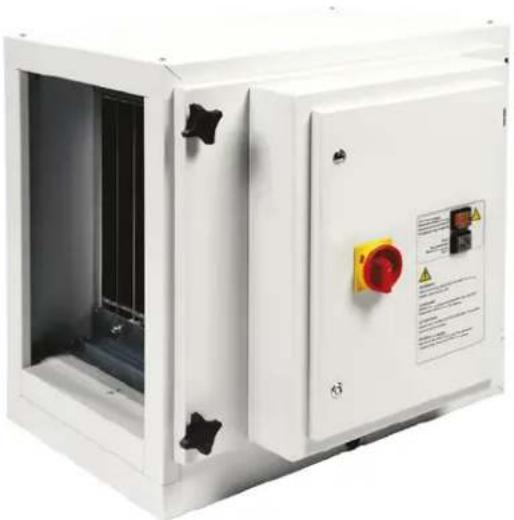
The extracted contaminated air passes the pre filter (fig. 2A) that takes out all larger particles. The pre filter also ensures a proper distribution of the airflow. After that, the air passes the ioniser (fig. 2B and 3B). The contaminations in the air are electrically charged by the high voltage (+10kV). These will then be deposited on the earthed plates (fig. 2C and 3C) by the collector voltage (+5kV). The after filter (fig. 2D) is the last filtration step and it also spreads the airflow. There are a main switch (fig. 4A), a high-voltage indicator (fig. 4B) and a reset button (fig. 4C) on the control panel. Please contact your dealer if the high voltage indicator is not working. Regularly check the functioning of the indicator when using the product, since it indicates that the electrostatic filter is properly charged. When the product produces a crackling sound, then it could be that the collector and/or ioniser are too dirty and that both need to be cleaned. Switch off the product with the main switch (fig. 4A). Wait for at least 10 seconds prior to opening the door that contains the filtration section. Subsequently, clean the collector and ionisation sections using EFC while adhering to the instructions on the EFC packaging. Check for touching collector lamellas. Consult your supplier if the lamellas are bent!
After closing the door of the housing switch on the unit by turning the main switch (fig. 4A) and press the reset button (fig. 4C). The distinguishing characteristics of the modular mounting of the ionising and collector sections are the very high separation efficiency (up to 98% of particles larger than 0.1 lm), its low air resistance and the userfriendliness while servicing the separate modules. Repairs shall only be carried out by authorised staff. Maintenance contracts are possible.
7.0 INSTALLATION
7.1 INSTALLATION SFE
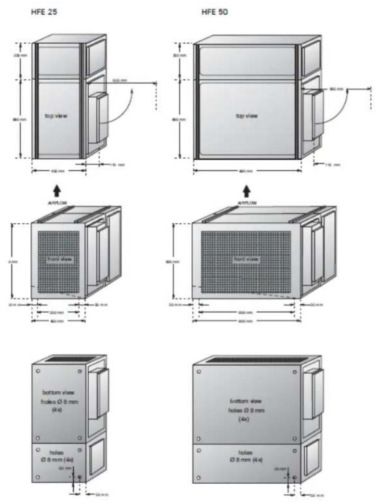
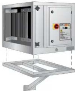
Check that the suspension construction is adequate prior to installing the product. Mount the SFE unit in the ducting system. It can be supported by a suspension bracket (fig 5A) as well as suspension by screw rods attached to the top of the SFE unit (fig. 5B). It is necessary to drill holes on the upper side for this purpose. It is also possible to place the unit on the ground providing sufficient space is allowed to use the drain plug.
Please consult the electrical diagram (separate leaflet, enclosed) when connecting the air cleaner to the mains. Use suitable rubber or neoprene cable with at least 4x1,5 mm2 wire area. Beware of possible differences in the mains power supply. The air cleaner can be stacked to a maximum of 4 units; the perforations and protrusions on the housing can be used for this purpose.
7.2 INSTALLATION HFE
Check that the suspension construction is adequate prior to installing the product. Use the profiles (fig. 6E) when mounting the product and attach the connection rings (fig. 6B), the lock rings (fig. 6C) and the sliding nuts (fig. 6D) (all supplied with the product) to the profiles. Use a suitable suspension chain (fig. 6A) in this way of mounting. You can also use the profiles (fig. 6J) together with screw rods M8 of suitable length. These should be mounted as illustrated. The following parts are used in this case: screw rod M8 (fig. 6F), self-locking nut (fig. 6G), lock ring (fig. 6H) and sliding nut (fig. 6I).
Please consult the electrical diagram (separate leaflet, enclosed) when connecting the air cleaner to the mains. Use suitable rubber or neoprene cable with at least 4 x 1,5 mm2 wire area. Beware of possible differences in the mains power supply. The position of the contact bridges may need to be changed as well as the connections inside the motor compartment. When connecting, pay attention to the direction of rotation of the motor!
Ensure at all times that the setting of the thermal relay corresponds with the nominal current rating of the motor for the applicable power mains. This rating is given on the motor identification plate.
8.0 MAINTENANCE
If you observe the necessary caution and carry out the simple maintenance and cleaning described below at regular intervals, then any problems will mostly be detected and corrected before they result in a total breakdown of the product. The indicated maintenance intervals can vary depending on the specific working and local conditions.
It is therefore recommended that the product is thoroughly inspected annually in addition to the indicated periodic maintenance. Please contact yoursupplier for this purpose.
TABLE 2. CLEANING TASKS
| Action When | |
| Clean the pre-filter, ioniser, collector and the afterfilter and check for damages | Every 2 weeks to 2 months, depending on the degree of usage / pollution |
| Clean the inside of the product and remove dust / grease from the filter compartment | Every 3 months |
| Clean the outside of the product with a mild detergent | Every 6 months |
| Check the door sealing material Every 12 months | |
8.1 PERIODIC MAINTENANCE
The maintenance activities in the table above can be carried out by the user; other activities are strictly reserved for qualified personnel.
8.2 CLEANING THE SEPERATE PARTS
Clean or replace the filters:
- When damaged
- When the ioniser and/or collector starts to make a crackling sound (indicator starts blinking or stops being lit)
- When the extraction capacity becomes inadequate
It is a matter of experience to determine when the product needs to be cleaned, since the nature and the degree of pollution depend strongly on the particular situation, humidity, intensity of use, etc. Nevertheless, the filters should be cleaned regularly (every 2 weeks up to 2 months).
To remove the filters, switch off the unit by turning the main switch (fig. 4A). Loosen the star knobs and open the door. Remove the pre filter, ioniser, collector and the after filter (in this sequence).
MAINTENANCE
Clean the pre and after filters in hot water (approx. 60^ C) added with a detergent for domestic use. This treatment can be repeated several times. Cleaning with a high-pressure spraying pistol is also possible. Allow for complete drying after cleaning.
Clean the ionizer and collector in hot water (approx. 60°C) to which a 2% EFC solution has been added. Cleaning using a high-pressure spraying pistol is also possible. Check the ionizer during washing for broken ionization wires. These broken wires can simply be replaced. Check the collector during washing for bent lamellas. These can be carefully straightened with a screwdriver. Lamellas in contact with each other can cause short-circuiting. Allow for complete drying after cleaning.
The filters can be put back in place in reversed order.
9.0 TROUBLESHOOTING
TABLE 3. SFE TROUBLESHOOTING
| Problem Possible cause Solution | ||
| Extraction capacity insufficient | Filters clogged or saturated | Clean the filters |
| False air is being sucked in | Check or replace the sealing material | |
| Dust or smoke from the outlet grid and / or indicator blinks or is not lit | Ionizer and / or collector are saturated or mounted incorrectly causing short circuiting | Clean the filters and mount the unit correctly |
| No power on filter cells Press the Reset button | ||
| Poor contacts in the ionizer and / or collector | Check and repair | |
| High voltage transformer defective | Replace the transformer | |
| High voltage PC board defective | Replace the PC board | |
| Short circuit in the ionizer and / or collector caused by bent lamellas | Check and repair | |
| Machine makes a crackling sound (= short-circuit) | Ionizer and / or collector are incorrectly mounted | Mount correctly |
| Ionizer and / or collector not totally dry | Allow for thorough drying after cleaning | |
| Bent collector lamellas Repair | ||
| Bent or broken ionization wires | Repair | |
| Ionizer and / or collector heavily polluted | Clean the filters | |
| Metal particles in ionizer and / or collector | Clean the filters | |
TABLE 4. HFE TROUBLESHOOTING
| Problem Possible cause Solution | |
| Motor does not start No mains voltage Check the mains voltage | |
| Loose contacts Repair the contacts | |
| Main switch defective Repair the main switch | |
| Blown fuse Replace the fuse | |
| Faulty transformer Repair the transformer | |
| Faulty relay Replace the relay | |
| Motor makes a humming sound but does not function | Motor uses 2 phases (only applies to 3 phase motors) Repair the phase connection |
| Motor capacitor defective or not connected (only applies to 1 phase motors) Repair, replace or connect the capacitor | |
| Motor stops automatically | Wrong direction of motor rotation Change the direction of rotation |
| Motor defective Replace the motor | |
10.0 IMAGES
Fig. 1
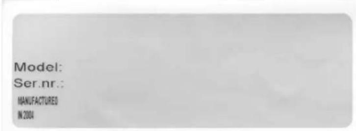
Fig. 2
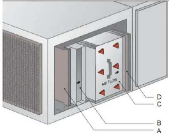
Fig. 3
B
C
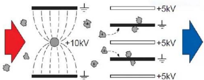
Fig. 4
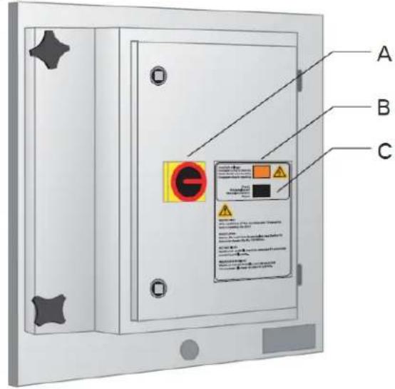
Fig. 5
natural_image
Exterior view of a stainless steel industrial control unit with mounting bracket (no visible text or symbols)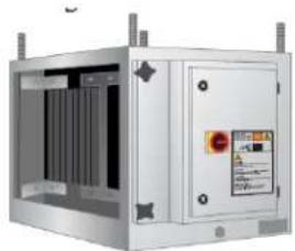
natural_image
Exterior view of a stainless steel industrial control unit with visible internal components and mounting brackets (no text or symbols)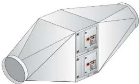
natural_image
3D rendering of a cylindrical industrial device with internal compartments and mounting holes (no text or symbols visible)Fig. 6
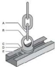
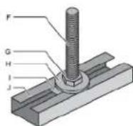
Fig. 7
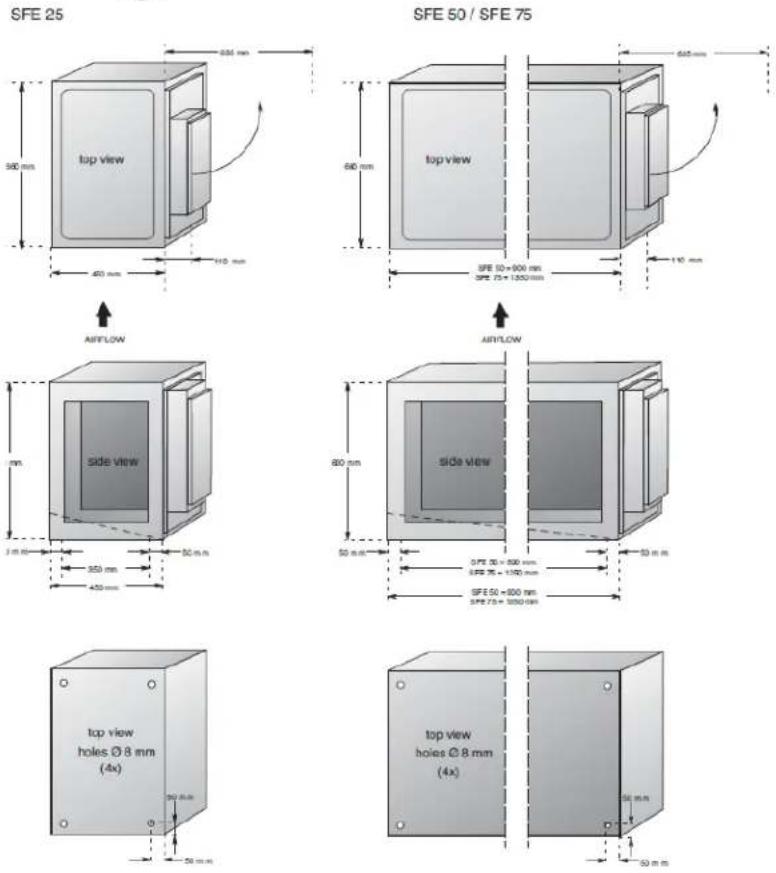
Fig. 8