
NetShelter SX AR7725 - Patch panel APC - Free user manual and instructions
Find the device manual for free NetShelter SX AR7725 APC in PDF.


| Product Type | Server Rack Enclosure |
| Brand | APC by Schneider Electric |
| Model | NetShelter SX AR7725 |
| Rack Standard | 19-inch |
| Height | 25U (approx. 44.5 mm per U) |
| Width | 600 mm (typical) |
| Depth | 1070 mm (typical) |
| Color | Black |
| Material | Steel |
| Weight | Approx. 100 kg |
| Max Load Capacity | 1000 kg |
| Mounting Rails | Front and rear, adjustable |
| U-Space Marking | Every third hole numbered |
| Included Accessories | 12 cage nuts, 1 cage nut tool, 12 pan head T30 screws, 3 wing screws, 3 foam insulation strips |
| Optional Duct Kit | 3U Duct Kit (AR7725) for airflow management |
| Safety | Two people recommended for installation, wear PPE |
| Assembly Required | Yes (tools not included: T30 screwdriver) |
| Documentation | Installation manual available |
| Support | Contact Schneider Electric Customer Care at www.apc.com/support |
| Recyclable Packaging | Yes, shipping materials are recyclable |
Frequently Asked Questions - NetShelter SX AR7725 APC
User questions about NetShelter SX AR7725 APC
0 question about this device. Answer the ones you know or ask your own.
Ask a new question about this device
Download the instructions for your Patch panel in PDF format for free! Find your manual NetShelter SX AR7725 - APC and take your electronic device back in hand. On this page are published all the documents necessary for the use of your device. NetShelter SX AR7725 by APC.
USER MANUAL NetShelter SX AR7725 APC
3U Duct Kit Installation
AR7725

natural_image
Technical line drawing of a multi-level server rack cabinet (no text or labels)Safety
CAUTION
ASSEMBLY HAZARDS
- Two people are recommended to install the kit.
- Wear appropriate Personal Protection Equipment, including safety glasses and
gloves.
Failure to follow these instructions can result in injury, or equipment damage.
NOTICE
Instructions show the bottom duct installed in U-space 3, but you may choose another U-space.
Unpacking
Open the carton and remove all parts.
Inventory
| Quantity Description | |
| 1 | Upper duct |
| 1 Lower duct | |
| 1 Rear baffle | |
| 3 Foam Insulation strips | |
| 12 Cage nuts | |
| 1 Cage nut tool | |
| 12 Pan head T30 screws | |
| 3 Wing screws | |
Note: The Upper and Lower Ducts are mirror images.
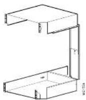
Inspection
Verify that all required components have been shipped with the kit. Contact Customer Support at www.apc.com if components are missing.
Inspect the parts for damage. Contact your shipper if damage is found. Schneider Electric is not responsible for damage sustained during shipment.
Please recycle

The shipping materials are recyclable. Save them for later use, or dispose of them appropriately.
Installation
Tools required (not provided)

T30 screwdriver
Install top and bottom duct insulation
Pull off the paper backing on the foam to adhere the 495mm foam (850-3255) to the side of both the top and bottom duct.


Identifying one U-space on the vertical mounting flange
When installing equipment, locate the top and bottom of a U-space on the mounting flanges. Every third hole on the mounting flanges of a NetShelter enclosure is numbered to indicate the middle of a U-space. A U-space consists of one of these numbered holes and one hole directly above and below it, as shown.

Install cage nuts for the bottom duct
Install cage nuts in the vertical rail in the correct locations.
Install cage nuts horizontally, with the ears engaging the sides of the square hole. Do NOT install cage nuts vertically with the ears engaging the top and bottom of the square hole.
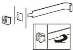
Insert the cage nut into the square hole by hooking one ear of the cage nut assembly through the far side of the hole.
Install the cage nuts on the interior of the vertical mounting flange. Place the cage nut tool (provided) on the other side of the cage nut and pull to snap it into position.
Note: To remove cage nuts, remove any attached screw then grasp the cage nut and squeeze the sides to release it from the square hole.
Install the bottom duct
① Align the bottom of the duct with the bottom of the U-space. Plan accordingly, knowing the Lower Duct is 3U high. Install two screws. Repeat for the other front mounting rail.

2 Loosen the wing screw on the left side of the Lower Duct and slide the rail toward the rear mounting rail.

3 Place the tab into the center of the appropriate U-space (in this example, U-space 3). Install two screws into the mounting rails. Re-tighten the wing screw.

Install the switch
Install the switch (not provided) per manufacturer's instructions

natural_image
Technical line drawing of a vertical structural frame with an arrow indicating direction (no text or symbols)Install the top duct
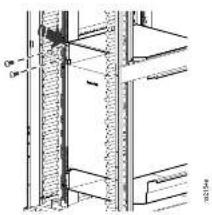
Install cage nuts in the vertical rail in the correct locations above the switch so the top duct makes proper contact. See Install cage nuts for the bottom duct installation steps for more information.
Set the Top Duct on the Switch and then install two screws into the cage nuts. Repeat for the other front mounting rail.
natural_image
Technical cross-section diagram of a structural column with embedded beams and supports (no text or labels)Install the Rear Baffle
① Assemble the Rear Baffle. Loosely tighten the wing screw so that it will allow the rear baffle to adjust.
2 Place the top tab into the Top Duct slot.
① Then place the bottom tab into the Bottom Duct slot. Lift the Bottom Duct up to the switch and tighten the wing screw.


natural_image
Technical line drawing of a structural component with an inset showing a circular detail (no text or symbols)Remove the backing paper to adhere the 620mm foam (850-3254) to the side of the assembled rear baffle.
Align the top of the baffle and the top of the foam strip. Start with the leading edge of the sticky side of the foam insulation and roll it forward (away from you) across the side edge of the baffle.

natural_image
Technical line drawing of a vertical shelving unit with internal compartments and a labeled component (no text or symbols present)Worldwide Customer Support
Contact Schneider Electric Customer Care at www.apc.com/support
© 2014 Schneider Electric. APC and the APC logo are owned by Schneider Electric Industries S.A.S., or its affiliated companies. All other trademarks are properly of their respective owners.

Brand : APC
Model : NetShelter SX AR7725
Category : Patch panel