
AMP60E - Amplifier Proel - Free user manual and instructions
Find the device manual for free AMP60E Proel in PDF.


| Product Type | Amplifier |
| Brand | Proel |
| Model | AMP60E |
| Power Output | 60W RMS per channel (stereo) or 120W bridged mono |
| Channels | 2 input channels with volume controls |
| Inputs | 2 x 1/4" jack, 2 x XLR combo, 1 x RCA stereo line input |
| Outputs | Speaker outputs via binding posts or SpeakON |
| Impedance | 4 ohms minimum per channel, 8 ohms bridged |
| Frequency Response | 20 Hz - 20 kHz (+/- 0.5 dB) |
| Signal-to-Noise Ratio | > 90 dB |
| Dimensions (W x H x D) | 483 x 88 x 300 mm (19" rack mount, 2U) |
| Weight | Approx. 10 kg |
| Power Supply | AC 230V, 50/60 Hz |
| Cooling | Forced air with variable speed fan |
| Protection Features | Short circuit, thermal, overvoltage, and DC protection |
| Controls | Power switch, volume controls per channel, EQ (bass/treble) |
| Indicators | Power LED, clip/limit LED per channel, signal present LED per channel |
| Construction | Steel chassis with rack ears |
| Operating Temperature | 0°C to 40°C |
| Accessories Included | Power cord, user manual |
| Intended Use | PA systems, monitor, and installation |
| Cleaning and Maintenance | Wipe with dry cloth; do not use liquids or solvents |
| Safety | Ensure proper ventilation; do not expose to rain or moisture |
| Spare Parts and Repairability | Contact Proel service center for qualified repair |
| General Information | User manual available for free download on notice-facile.com |
Frequently Asked Questions - AMP60E Proel
User questions about AMP60E Proel
0 question about this device. Answer the ones you know or ask your own.
Ask a new question about this device
Download the instructions for your Amplifier in PDF format for free! Find your manual AMP60E - Proel and take your electronic device back in hand. On this page are published all the documents necessary for the use of your device. AMP60E by Proel.
USER MANUAL AMP60E Proel
Watch for these symbols:
The lightning flash with arrowhead symbol within an equilateral triangle is intended to alert the user to the presence of uninsulated “dangerous voltage” within the product’s enclosure, that may be of sufficient magnitude to constitute a risk of electric shock to persons.

The exclamation point within an equilateral triangle is intended to alert the user to the presence of important operating and maintenance (servicing) instructions in the literature accompanying the appliance.
- %ead these instructions.
- Keep these instructions.
- Heed all warnings.
- Follow all instructions.
- Do not use this apparatus near water.
-
Clean only with dry cloth.
-
Do not block any ventilation openings. +nstall in accordance with the manufacturer's instructions.
- Do not install near any heat sources such as radiators, heat registers, stoves, or other apparatus (including amplifiers) that produce heat.
- Do not defeat the safety purpose of the polarized or grounding-type plug. A polarized plug has two blades with one wider than the other. A grounding-type plug has two blades and a third grounding prong. The wide blade or the third prong are provided for your safety. +f the provided plug does not fit into your outlet, consult an electrician for replacement of the obsolete outlet.
- Protect the power cord from being walked on or pinched, particularly at plugs, convenience receptacles, and the point where they exit from the apparatus.
- Only use attachments/accessories specified by the manufacturer.

-
Use only with the cart, stand, tripod, bracket, or table specified by the manufacturer, or sold with the apparatus. When a cart is used, use caution when moving the cart/apparatus combination to avoid injury from tip-over.
-
Unplug this apparatus during lightning storms or when unused for long periods of time.
- %efer all servicing to qualified service personnel. ≥servicing is required when the apparatus has been damaged in any way, such as power supply cord or plug is damaged, liquid has been spilled or objects have fallen into the apparatus, the apparatus has been exposed to rain or moisture, does not operate normally, or has been dropped.
- Warning: to reduce the risk of fire or electric shock, do not expose this apparatus to rain or moisture.
- Do not expose this equipment to dripping or splashing and ensure that no objects filled with liquids, such as vases, are placed on the equipment.
- To completely disconnect this apparatus from the ac mains, disconnect the power supply cord plug from the ac receptacle.
- The mains plug of the power supply cord shall remain readily operable.
- This apparatus contains potentially lethal voltages. To prevent electric shock or hazard, do not remove the chassis, input module or ac input covers. No user serviceable parts inside. %efer servicing to qualified service personnel.
- This owner's manual should be considered as a part of the product, it must accompany it at all times, and it needs to be delivered to the new user when this product is sold. +n this way the new owner will be aware of all the installation, operating and safety instructions.
- This apparatus should only be connected to a power source of type specified in this owner's manual or on the unit.
- You can clean the exterior of the unit with compressed air or with a dry cloth.
- Don't clean the unit using solvents like trichloroethylene, thinners, alcohol, or other volatile or flammable fluids.
- To reduce the risk, close supervision is necessary when the product is used near children.
DISPOSAL OF OLD ELECTRICAL & ELECTRONIC EQUIPMENT

This marking shown on the product or its literature, indicates that it should not be disposed with other household wastes at the end of its working life. To prevent possible harm to the environment or human health from uncontrolled waste disposal, please separate this from other types of wastes and recycle it responsibly to promote the sustainable reuse of material resources. Household users should contact either the retailer
where they purchased this product, or their local government office, for details of where and how they can take this item for environmentally safe recycling. Business users should contact their supplier and check the terms and conditions of the purchase contract. This product should not be mixed with other commercial wastes for disposal.
DECLARATION OF CONFORMITY

The product is in compliance with:
EMC Directive 2014/30/EU, LVD Directive 2014/35/EU, %oH≥ Directive 2011/65/EU and 2015/863/EU, WEEE Directive 2012/19/EU.
CONDITIONS OF USE
Proel do not accept any liability for damage caused to third parties due to improper installation, use of non-original spare parts, lack of maintenance, tampering or improper use of this product, including disregard of ascertainable and applicable safety standards. Proel strongly recommends that this apparatus must be installed taking into consideration all current National, Federal, ≥tate and Local regulations. The product must be installed by qualified personal. Please contact the manufacturer for further information.
PACKAGING7 SHIPPING AND COMPLAINT
This unit package has been submitted to +≥TA 1A integrity tests. We suggest you control the unit conditions immediately after unpacking it.
+f any damage is found, immediately advise the dealer. Keep all unit packaging parts to allow inspection.
Proel is not responsible for any damage that occurs during shipment.
Products are sold "delivered ex warehouse" and shipment is at charge and risk of the buyer.
Possible damages to unit should be immediately notified to forwarder. Each complaint for manumitted package should be done within eight days from product receipt.
WARRANTY AND PRODUCTS RETURN
Proel products have operating warranty and comply their specifications, as stated by manufacturer.
Proel warrants all materials, workmanship and proper operation of this product for a period of two years from the original date of purchase. +f any defects are found in the materials or workmanship or if the product fails to function properly during the applicable warranty period, the owner should inform about these defects the dealer or the distributor, providing receipt or invoice of date of purchase and defect detailed description. This warranty does not extend to damage resulting from improper installation, misuse, neglect or abuse. Proel ≥.p.A. will verify damage on returned units, and when the unit has been properly used and warranty is still valid, then the unit will be replaced or repaired. Proel ≥.p.A. is not responsible for any "direct damage" or "indirect damage" caused by product defectiveness.
:
IMPORTANT SAFETY INSTRUCTIONS 2:
DISPOSAL OF OLD ELECTRICAL & ELECTRONIC EQUIPMENT 3:
DECLARATION OF CONFORMITY 3:
CONDITIONS OF USE 3:
PACKAGING, SHIPPING AND COMPLAINT....3:
WARRANTY AND PRODUCTS RETURN....3:
INTRODUCTION 5:
DESCRIPTION 5:
MAIN FUNCTIONS....5:
MAIN PANEL OPERATIONS....5:
1: POWER....5:
2: MASTER....5:
3: TREBLE....6:
4: BASS....6:
5: INPUT 1....6:
6: INPUT 2 6:
7: AUX....6:
8: INPUT 1 6:
9: MIC/PH/LINE SWITCH for INPUT 1....7:
10: INPUT 1 PRIORITY....7:
11: INPUT 2....7:
12: MIC/PH/LINE SWITCH for INPUT 2....7:
13: AUX IN (RCA)....7:
14: LOUDSPEAKERS OUTPUT 7:
14.1: Constant impedance line: 8:
14.2: Constant voltage line: 8:
15: AC\~ SOCKET 8:
16: FUSE holder....9:
17: MAINS SELECTOR....9:
18: CONNECTION EXAMPLE....9:
19: TECHNICAL SPECIFICATION.... 10:
INTRODUCTION
Thank you for choosing a PROEL product. Please take some time to read this manual to understand all the features of your system and take advantage of all its performance capabilities. All PROEL products are CE approved and designed for continuous use in professional applications.
DESCRIPTION
AMP35E and AMP60E are 35W or 60W professional mixer amplifiers with constant voltage (70/100V) or constant impedance (4/8Ω) output. This new series of power amplifiers has been conceived to fulfil the needs of a wide range of Commercial Audio installations in the most flexible and professional way. The new range responds to precise operating criteria and it has been designed and tested to guarantee maximum reliability in prolonged use.
MAIN FUNCTIONS
- Speakers overload and short-circuit protection circuit
- Led start-up indicator
- Main level control (Master)
- Separated Level Controls for 1 ÷ 2 and AUX inputs
- Bass and Treble tone adjustment
• 2 MIC / MIC Phantom 48V / LINE inputs balanced on Euroblock terminals
• 1 AUX Line RCA Input - MIC 1 Input with priority function
- 4 outputs, two at constant impedance (8/4Ω) and two at constant voltage (70/100V)
MAIN PANEL OPERATIONS
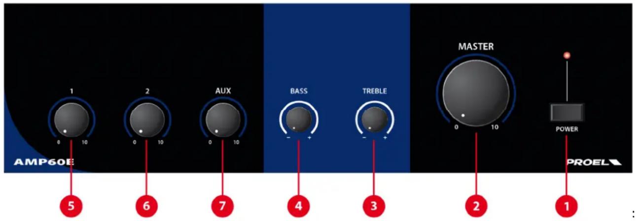
1 POWER
Main switch with LED indicator.
2 MASTER
Main level control.
3 TREBLE
The TREBLE control is used to adjust the high frequency band. The treble range is -10 dB to +10 dB. Turning the knob to the right boosts the corresponding frequency band, while turning to the left attenuates the band.
4 BASS
The BASS control is used to adjust the low frequency band. The bass range is -10 dB to +10 dB. Turning the knob to the right boosts the corresponding frequency band, while turning to the left attenuates the band.
5 INPUT 1
Level control of the signal connected to the input 1, which can be either a microphone or a line level devise (see further).
6 INPUT 2
Level control of signal connected to the input 2, which can be either a microphone or a line level devise (see further).
7 AUX
Level control of signal connected to the AUX input.

8 INPUT 1
Balanced or unbalanced input on 3.5mm pitch Euroblock connector.
This input can be used to connect low impedance dynamic microphones (30-600 ohm), condenser microphones with phantom power supply and audio sources with line level signal output (e.g. radio tuners, television receivers, media players, etc.).
a) Connection of a Balanced line to the INPUT:

b) Connection of a Unbalanced line to the INPUT:

9 MIC/PH/LINE SWITCH for INPUT 1
Use this switch to select the type of source connected to the input:
MIC for a dynamic microphones
PH for a condenser microphone with phantom power
LINE for a line level source.

WARNING
It is recommended to set the input level at minimum before changing this switch position then gradually raise up the level, otherwise when the "PH" phantom supply is engaged it would produce a loud "bump" from the audio system8
Some line level devices don't support the "PH" phantom supply, so it can cause permanent damages to the connected devises if engaged8 To avoid that, it is recommended to disconnect temporarily the Euroblock connector before changing the switch position from MIC9PH to LINE8:
10 INPUT 1 PRIORITY
INPUT 1 PRIORITY potentiometer sets the threshold level of the INPUT 1 signal that mutes temporarily the INPUT 2 and AUX channels. Priority function can be used when a microphone connected to INPUT1 is used to make a voice announcement: if turned fully counter-clockwise it has no effect on the other channels, turning it clockwise sets the level of intervention.
11 INPUT 2
Balanced or unbalanced input on 3.5mm pitch Euroblock connector with same connection as INPUT 1.
12 MIC/PH/LINE SWITCH for INPUT 2
Set this selector for the source type signal connected to this input: the sensitivity is the same of INPUT 1.
13 AUX IN (RCA)
These are two RCA female connectors that accept two RCA plug from LEFT and RIGHT channels of a line level stereo source (e.g. radio tuners, television receivers, media players, etc.). Each RCA input is wired as follows:
$$ \text { Tip } = + \text { positive or "hot" } $$
$$ \text { Sleeve } = \text { shield or ground } $$
14 LOUDSPEAKERS OUTPUTS
The device allows the connection of constant impedance speakers (4Ω or 8Ω) or constant voltage speakers at (70/100V) on 5.08 mm pitch Euroblock connector.
A Class 2 wiring is needed for fixed installation. This connector can accept 0.5 ÷ 2.5 mm^-2 / 20 ÷ 14 AWG size cables.

WARNING
DO NOT CONNECT MIXED CONSTANT IMPEDANCE AND CONSTANT VOLTAGE SPEAKERS.
To avoid the risk of electric shocks, never touch the amplifier outputs during operation8
1481 Constant impedance line
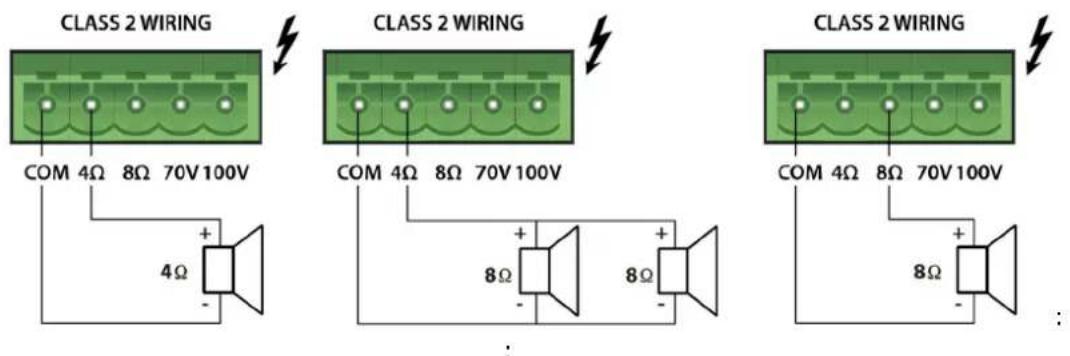
Connect the constant impedance line between "COM" and "4Ω" or "8 Ω" terminals.
- To ensure maximum performance, the total impedance of the loudspeakers connected to the line must be equivalent to the output impedance of the amplifier.
- The total power of the connected loudspeakers should not be lower than the amplifier's output power.
- It is advisable to reduce as much as possible the wires' length and to increase the cable section according to the distance covered.
1482 Constant voltage line:

MAX. 35W FOR AMP35E
MAX. 60W FOR AMP60E
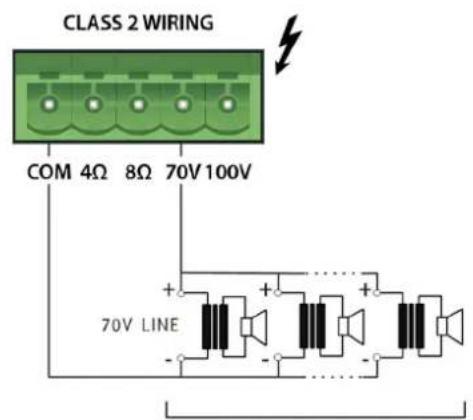
MAX. 35W FOR AMP35E
MAX. 60W FOR AMP60E
Connect the constant voltage line (100V or 70V) between "COM" and "100V" (or "70V") terminals.
- All the loudspeakers must be equipped with a transformer having an input voltage equal to that supplied by the amplifier.
- The sum of the loudspeaker power must not exceed the maximum output power of the amplifier.
15 AC\~ SOCKET
Here's where you plug in your mains supply cord. You should always use the mains cord supplied with the device. Be sure that your device is turned off before you plug the mains supply cord into an electrical outlet.
16 FUSE holder
Here is where the mains protection fuse is placed.
REPLACE THE PROTECTION FUSE ONLY WITH THE SAME TYPE.

IF, AFTER THE REPLACEMENT, THE FUSE IS BLOWN AGAIN, DO NOT TRY TO REPLACE IT AGAIN AND CONTACT THE NEAREST PROEL SERVICE CENTER.
17 MAINS SELECTOR
This switch sets the AC voltage line of your country (usually it is set by factory and isn't necessary to change it). The 115V setting is for mains lines in the range of 100-120V\~ and 230V setting is for mains lines in the range of 220-240V\~.

WARNING: an incorrect setting of AC LINE VOLTAGE could seriously damage the device!
18 CONNECTION EXAMPLE
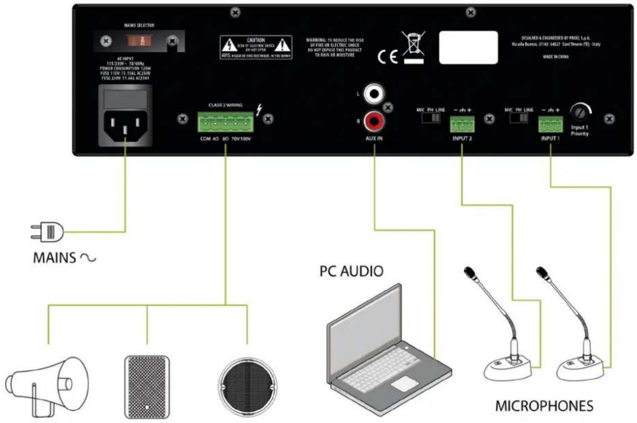
: :
19 TECHNICAL SPECIFICATION
| Model: AMP35E AMP60E | ||
| Output power RMS 35 W 60 W | ||
| Inputs | 2x MIC/PH/LINE (3.5mm EUROBLOCK)1x AUX (RCA L & R) | 2x MIC/PH/LINE (3.5mm EUROBLOCK)1x AUX (RCA L & R) |
| Input Sensitivity | MIC: -50 dBv / 1 kΩ balancedPH: as above with 24V phantom supplyLINE: -10 dBv / 100 kΩ balancedAUX: -10 dBv / 47 kΩ unbalanced | MIC: -50 dBv / 1 kΩ balancedPH: as above with 24V phantom supplyLINE: -10 dBv / 100 kΩ balancedAUX: -10 dBv / 47 kΩ unbalanced |
| Controls | MASTER VOLUME CONTROL1 TREBLE TONE CONTROL1 BASS TONE CONTROL2 MIC/LINE VOLUME CONTROLS1 AUX VOLUME CONTROL1 PRIORITY on MIC/LINE 1 | MASTER VOLUME CONTROL1 TREBLE TONE CONTROL1 BASS TONE CONTROL2 MIC/LINE VOLUME CONTROLS1 AUX VOLUME CONTROL1 PRIORITY on MIC/LINE 1 |
| Tone Controls | Shelving +/- 10 dB @ 10 kHzShelving +/- 10 dB @ 100 Hz | Shelving +/- 10 dB @ 10 kHzShelving +/- 10 dB @ 100 Hz |
| Loudspeakers outputs 100/70V/8Ω/4Ω 100/70V/8Ω/4Ω | ||
| Output Connector 5.08 mm | EUROBLOCK 5.08 mm EUROBLOCK | |
| Frequency response 60Hz -20KHz (-3dB) 60Hz -20KHz (-3dB) | ||
| Distortion (THD) | < 0.5% (@ Pnom 1KHz) | < 0.5% (@ Pnom 1KHz) |
| S9N Ratio | MIC: ≥70dBLINE: ≥70dBAUX: ≥80dB | MIC: ≥70dBLINE: ≥70dBAUX: ≥80dB |
| Operating temperature | 0 ÷ +45°C | 0 ÷ +45°C |
| Power Supply | 100-120V~ 50/60Hz (select 115V) or220-240V~ 50/60Hz (select 230V) | 100-120V~ 50/60Hz (select 115V) or220-240V~ 50/60Hz (select 230V) |
| Power Consumption | 72 W 120 W | |
| Dimensions (LxHxP) | 289 x 91 x 232 mm | 289 x 91 x 232 mm |
| Weight | 4.3 Kg | 5.3 Kg |
IMPORTANTI ISTRUZIONI qI SIKUREZZA

10: INPUT 1 PRIORITY....16:
11: INPUT 2....16:
12: MIC/PH/LINE SWITCH for INPUT 2.... 16:
13: AUX IN (RCA).... 16:
14: LOUDSPEAKERS OUTPUT 16:
(World Headquarters - Factory)
- DISPOSAL OF OLD ELECTRICAL & ELECTRONIC EQUIPMENT
- DECLARATION OF CONFORMITY
- CONDITIONS OF USE
- PACKAGING7 SHIPPING AND COMPLAINT
- WARRANTY AND PRODUCTS RETURN
- INTRODUCTION
- DESCRIPTION
- MAIN FUNCTIONS
- POWER
- MASTER
- TREBLE
- BASS
- INPUT 1
- INPUT 2
- AUX
- INPUT 1
- MIC/PH/LINE SWITCH for INPUT 1
- WARNING
- INPUT 1 PRIORITY
- INPUT 2
- MIC/PH/LINE SWITCH for INPUT 2
- AUX IN (RCA)
- LOUDSPEAKERS OUTPUTS
- Constant impedance line
- Constant voltage line:
- AC\~ SOCKET
- FUSE holder
- MAINS SELECTOR
- CONNECTION EXAMPLE
- IMPORTANTI ISTRUZIONI qI SIKUREZZA
Brand : Proel
Model : AMP60E
Category : Amplifier