
ISC-D109L - Detector Dahua Technology - Free user manual and instructions
Find the device manual for free ISC-D109L Dahua Technology in PDF.

| Product Type | Walk-through Metal Detector |
| Brand | Dahua Technology |
| Model | ISC-D109L |
| Detection Zones | 9 (3 left, 3 right, 3 middle) |
| Sensitivity Range | 0–399 per zone |
| Preset Programs | 99 (including custom) |
| Alarm Tones | 99 selectable |
| Alarm Volume | 10 levels (0–9), including mute |
| Alarm Duration | 0–9 seconds |
| Frequency Adjustment | 1–20 or auto-search |
| IR Modes | 4 (both on, both off, front only, rear only) |
| Counter Modes | Entry+Exit+ or Entry+Exit- |
| Power Supply | AC 100–240 V, 50/60 Hz (via included adapter) |
| Dimensions (H × W × D) | Approx. 2000 × 850 × 600 mm |
| Weight | Approx. 70 kg |
| Operating Temperature | 0 °C to 40 °C |
| Storage Humidity | 10%–90% RH (non-condensing) |
| Material | Metal and ABS plastic |
| Self-Diagnosis | Yes, with error codes |
| Password Protection | 5-digit password |
| Network Upgrade | Via ConfigTool |
| Safety Compliance | Very low frequency, safe for pacemakers |
| Included Accessories | Left/right panels, beam, power adapter, ribbon cables, screws, wrench, cable ties, QR code, installation guide |
Frequently Asked Questions - ISC-D109L Dahua Technology
User questions about ISC-D109L Dahua Technology
0 question about this device. Answer the ones you know or ask your own.
Ask a new question about this device
Download the instructions for your Detector in PDF format for free! Find your manual ISC-D109L - Dahua Technology and take your electronic device back in hand. On this page are published all the documents necessary for the use of your device. ISC-D109L by Dahua Technology.
USER MANUAL ISC-D109L Dahua Technology
Walk-through Metal Detector
User's Manual

natural_image
Abstract geometric composition with gray and blue color blocks (no text or symbols)Foreword
General
This manual introduces the structure, installation, and configuration of the walk-through metal detector (hereinafter referred to as "the detector"). Read carefully before using the detector, and keep the manual safe for future reference.
Safety Instructions
The following signal words might appear in the manual.
| Signal Words Meaning | ||
 | DANGER | Indicates a high potential hazard which, if not avoided, will result in death or serious injury. |
 | WARNING | Indicates a medium or low potential hazard which, if not avoided, could result in slight or moderate injury. |
 | CAUTION | Indicates a potential risk which, if not avoided, could result in property damage, data loss, reductions in performance, or unpredictable results. |
 | TIPS | Provides methods to help you solve a problem or save time. |
 | NOTE | Provides additional information as a supplement to the text. |
Revision History
| Version | Revision Content | Release Time |
| V1.0.0 | First release. | June 2022 |
Privacy Protection Notice
As the device user or data controller, you might collect the personal data of others such as their face, fingerprints, and license plate number. You need to be in compliance with your local privacy protection laws and regulations to protect the legitimate rights and interests of other people by implementing measures which include but are not limited: Providing clear and visible identification to inform people of the existence of the surveillance area and provide required contact information.
About the Manual
- The manual is for reference only. Slight differences might be found between the manual and the product.
- We are not liable for losses incurred due to operating the product in ways that are not in compliance with the manual.
- The manual will be updated according to the latest laws and regulations of related jurisdictions. For detailed information, see the paper user's manual, use our CD-ROM, scan the QR code or visit our official website. The manual is for reference only. Slight differences might be found between the electronic version and the paper version.
- All designs and software are subject to change without prior written notice. Product updates might result in some differences appearing between the actual product and the manual. Please contact customer service for the latest program and supplementary documentation.
- There might be errors in the print or deviations in the description of the functions, operations and technical data. If there is any doubt or dispute, we reserve the right of final explanation.
- Upgrade the reader software or try other mainstream reader software if the manual (in PDF format) cannot be opened.
- All trademarks, registered trademarks and company names in the manual are properties of their respective owners.
- Please visit our website, contact the supplier or customer service if any problems occur while using the device.
- If there is any uncertainty or controversy, we reserve the right of final explanation.
Important Safeguards and Warnings
This section introduces content covering the proper handling of the detector, hazard prevention, and prevention of property damage. Read carefully before using the detector, and comply with the guidelines when using it.
Transportation Requirements

Transport the detector under the allowed humidity and temperature conditions.
Storage Requirements

- Keep the detector away from dampness, dust or soot.
- Store the detector under the allowed humidity and temperature conditions.
Installation Requirements

- Do not place or install the detector in a place exposed to sunlight or near the heat source.
- Keep the detector installed horizontally on a stable place to prevent it from falling.
- Install the detector in a well-ventilated place, and do not block the ventilation of the detector.
Operation Requirements

- Do not drop or splash liquid onto the detector, and make sure that there is no object filled with liquid on the detector to prevent liquid from flowing into the detector.
- Operate the detector within the rated range of power input and output.
- Do not disassemble the detector.
- Use the detector under the allowed humidity and temperature conditions.
Maintenance Requirements

WARNING
- Use the battery of specified manufacturer. When replacing battery, make sure that the same type is used. Improper battery use might result in fire, explosion, or inflammation.
- Use the recommended power cables in the region and conform to the rated power specification.
- Use the power adapter provided with the detector; otherwise, it might result in people injury and device damage.

- Use power supply that meets ES1 but does not exceed PS2 limits defined in IEC 62368-1. For specific power supply requirements, refer to device labels.
- Connect the detector (I-type structure) to the power socket with protective earthing.
- The appliance coupler is a disconnection device. Keep the angle for easy operation.
Table of Contents
Foreword....
Important Safeguards and Warnings....III
1 Overview....1
1.1 Introduction ...... 1
1.2 Technical Advantages .... 1
2 Structure 2
2.1 Dimensions....2
2.2 Ports....3
3 Installation....4
3.1 Checklist....4
3.2 Environment Requirements 4
3.3 Installing Detector 5
3.4 Multiple Walk-through Site Installation 7
4 Configuration 9
4.1 Controls and Displays....9
4.2 Menu Description 10
4.3 Login....11
4.4 Selecting Program 11
4.5 Setting All-zone Sensitivity....12
4.6 Resetting Counter 13
4.7 Adjusting Alarm Volume......13
4.8 Changing Alarm Tone....14
4.9 Adjusting Alarm Time....14
4.10 Adjusting Frequency....14
4.11 Setting Each-zone Sensitivity....15
4.12 Setting Counter Mode....16
4.13 Setting IR Mode....17
4.14 Changing Password....18
4.15 Diagnosis....18
4.16 Viewing IP and Version....19
4.17 Factory Default....19
5 Upgrade and Changing IP 21
5.1 Configuring Network....21
5.2 Searching for Detector....21
5.3 Upgrading Detector 22
5.4 Changing IP....22
6 FAQ 24
Appendix 1 Cybersecurity Recommendations....26
1 Overview
1.1 Introduction
The walk-through metal detector uses electromagnetic field to detect carry-on metal articles, and uses sound and light alarm to indicate excessive carry-on metal. The detector consists of a host, a high-frequency signal generator, a signal receiver, and infrared sensors, and is designed with a beautiful appearance, strong metal detection capability, 9 detection zones, a unique Internet remote management system, and light weight. The walk-through metal detector can be widely used in sports meetings, conferences, schools and other scenarios.
1.2 Technical Advantages
- Optimized IR Sensors Infrared (IR) sensors with less false or missed alarms, automatic alarm and pass statistics, and IR detection with multiple detection modes.
- Counter Mode One-way counting or two-way counting.
- Digital Signal Processor Based Technology The digital signal processing and filtering system ensures immunity to electromagnetic interference.
- Adjustable Sensitivity The sensitivity of each zone can be individually adjusted to meet differentiated sensitivity requirements.
- Password Protection The five-digit password limits programming access and protects parameter configuration.
- Electromagnetic Field Emission Technology Complies with the current international security standards by using Very Low Frequency electromagnetic fields, with no harm to pacemakers, pregnant women, or magnetic storage devices.
- Adjustable Sound and Volume Up to 99 alarm tones with 10 adjustable volume levels (mute mode included), and alarm duration (0 s–10 s).
- Adjustable Frequency Automatically searches and applies suitable operating frequency. Also supports manual adjustment (0–20).
- Multiple Scenarios Designed with 99 programs with different sensitivities for various application needs.
- Self Diagnosis Automatic diagnosis with an error code showing the results.
- Upgrade Supports firmware upgrade through network.
2 Structure
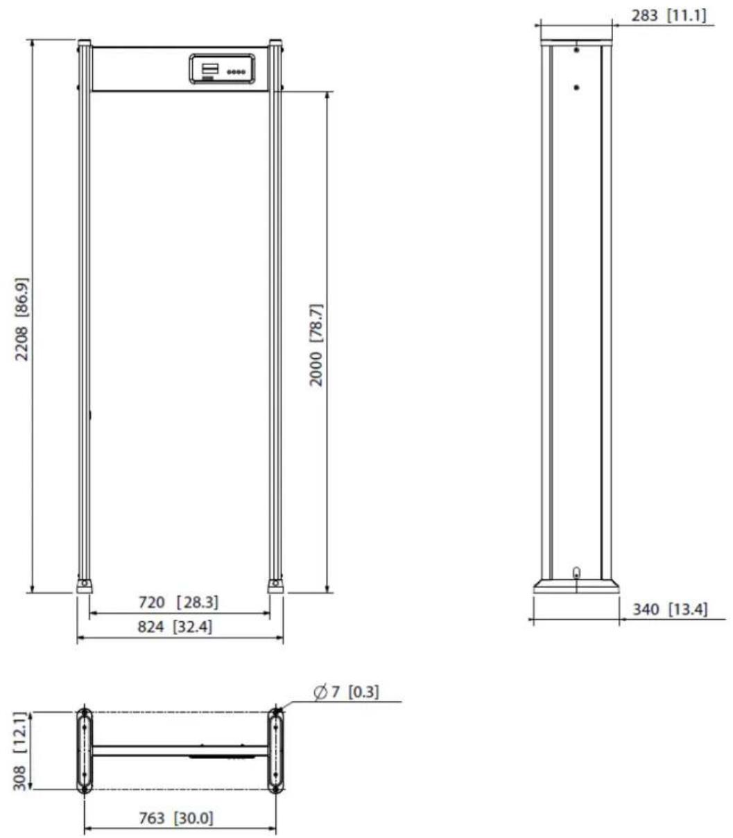
2.1 Dimensions
Figure 2-1 Dimensions (mm [inch])
2.2 Ports
Figure 2-2 Port (1)
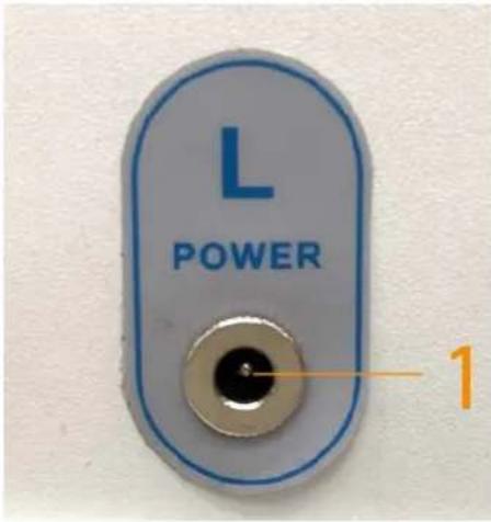
Figure 2-3 Port (2)
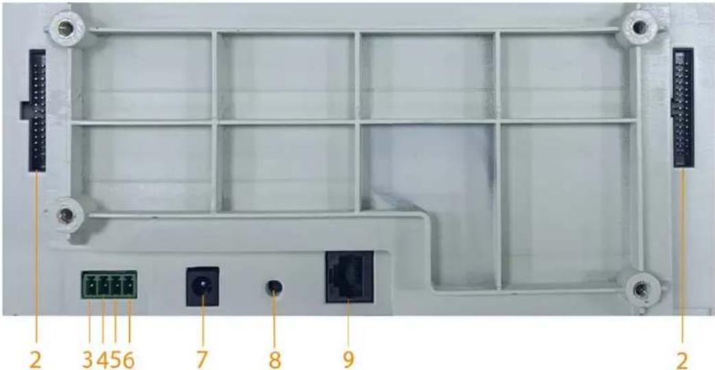
Table 2-1 Port description
| No. | Name Description | |
| 1 | Power input | Connects to the power adapter to get power supply. |
| 2 | Ribbon cable port | Connects the host to the panels with the ribbon cables. |
| 3 RS-485 A | Communication ports. | |
| 4 RS-485 B | ||
| 5 NO | Outputs alarm signals to external alarm devices. | |
| 6 COM | ||
| 7 | Power input | Connects to this port if you need to test the host. |
| 8 Reset button | Press and hold the button for more than 5 s to restore the detector to factory default settings. | |
| 9 | Ethernet port | Connects to network with a network cable. |
3 Installation
3.1 Checklist
After receiving the product, check against the table below. If there are any problems, contact our after-sales service.
Table 3-1 Checklist
| No. | List Description | ||
| 1 | Overall packaging | Appearance Obvious damage | |
| Packaging Accidental impact | |||
| Accessories Complete or not | |||
| 2 | Host | Appearance Obvious damage | |
| Model | Whether consistent with the order contract | ||
Table 3-2 Packing list
| Name Quantity | |
| Left panel 1 | |
| Right panel 1 | |
| Beam (with host) 1 | |
| Power adapter (power input) 1 | |
| Ribbon cable 2 | |
| Fixing screws (M8 × 60) 4 | |
| Wrench | 1 |
| Cable zip tie | 2 |
| Self-adhesive cable zip tie mount | 2 |
| QR code | 1 |
| Installation guide | 1 |
3.2 Environment Requirements
• The ground is flat and sturdy
The ground should be flat and firmly supporting to prevent vibration. If there is a vibrating metal structure under the ground, there can be unnecessary alarm when people pass through the metal detector.
Do not install the detector on a metal ground.
- Keep away from fixed metal objects
Large metal objects that are fixed or immobile should be at least 50 cm away from the detector (detecting large metal objects) because they might make the detector more susceptible to vibration.

The distance in this section is the recommended distance. The actual installation distance depends on the installation site conditions.
- Keep away from moving metal objects Large moving metal objects should be kept 0.5 m to 2 m away from the detector to avoid false alarms. Depending on the size of the metal object, the distance between the moving metal object and the detector might vary.
- Keep away from radioactive electronic interference The distance between the electronic interference source and the receiving coil should be as large as possible. The recommended distance is 0.5 m to 4 m. However, the actual distance needs to be based on specific circumstances. For example, you can go through a metal detector with a source of interference until the best position is found. Interference can occur from electronic control panels, radios and computers, image displays, high-power motors and transformers, AC wires, transistor control circuits, flash fluorescent tubes, arc welding equipment, and more.
- Keep away from conductive electronic interference Connect the power cord to a line that is not connected to other large loads, such as high-power motors, because they can cause a large power or voltage shock in the line.
3.3 Installing Detector
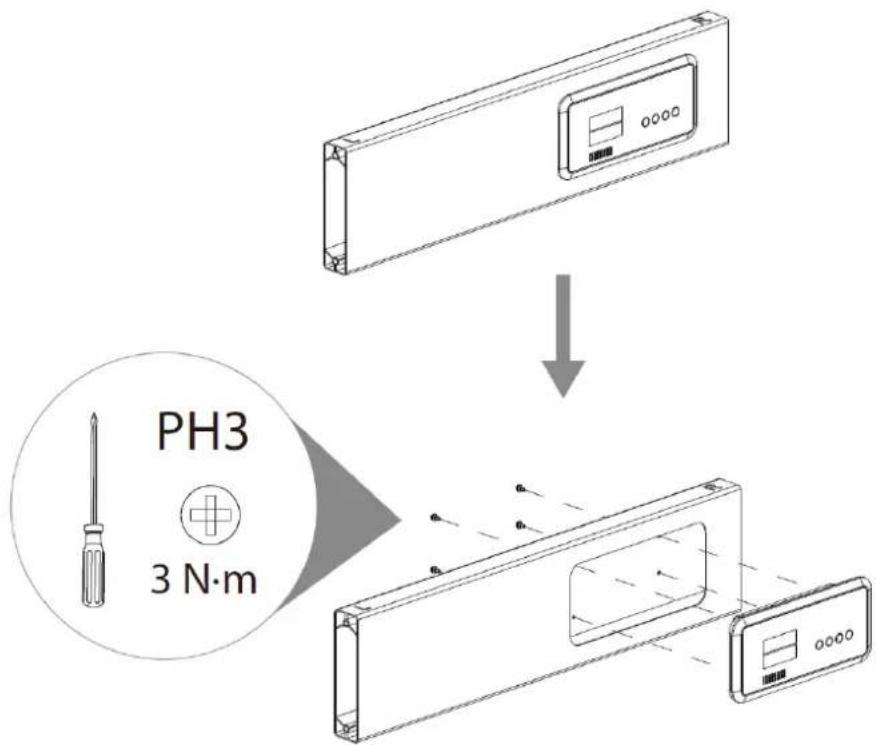
Step 1 Open the packing box and take out the accessories.
Step 2 Loosen the 4 fixing screws with a crosshead screwdriver to separate the host box and the beam.
Figure 3-1 Remove host box
Step 3 Attach the two ribbon cables to the host box.
Figure 3-2 Attach ribbon cables
natural_image
Technical diagram of a cable connector assembly with a magnified inset showing internal structure (no text or symbols)Step 4 Feed the ribbon cables through the opening of the beam, thread them out from the two sides, and then attach the host box back to the beam with the fixing screws.
Figure 3-3 Attach host box
Step 5 Connect the left ribbon cable to the left panel, and then use the wrench to attach the left side of the beam to the left panel with two M8 × 60 screws. Connect the right ribbon cable
to the right panel, and then attach the right side of the beam to the right panel with two M8 × 60 screws.
Figure 3-4 Attach panels
Step 6 Stand the detector up, connect the power supply, and then secure the power cord to avoid accidental plug-off during use.
1) Attach the self-adhesive cable zip tie mount to one panel.
2) Connect the power supply.
3) Wind the power cord to the cable zip tie mount, and then feed the cable zip tie through the mount to tie up the power cord.
Figure 3-5 Connect and secure power cord
natural_image
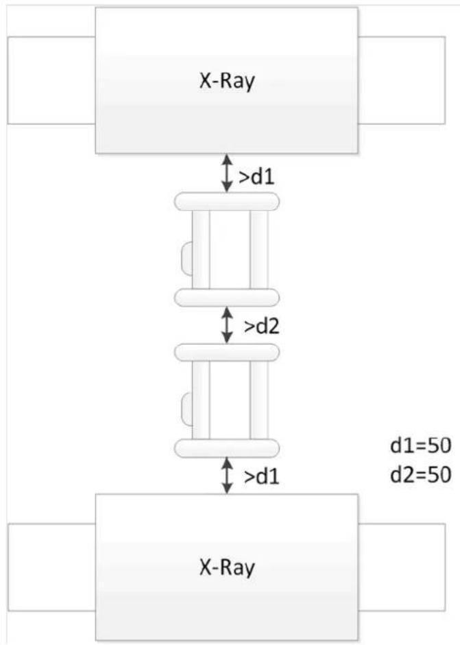
Technical line drawing of a vertical electrical meter with a close-up inset showing wiring and a plug (no text or symbols)3.4 Multiple Walk-through Site Installation
When installing multiple devices, space the devices at least 50 cm (d2), and also space the device and X-ray security screening machine larger than 50 cm (d1). This recommended spacing can make
the little metal objects (such as coin) detected. If you install the devices with space smaller than 50 cm, there might be false alarm. If the spacing needs to be shortened because of limited installation site, you need to adjust the frequency, lower the security level and sensitivity according to the actual situation; otherwise, small metal objects might not be detected.
Figure 3-6 Multiple walk-through detectors site installation
flowchart
graph TD
    A["X-Ray"] -->|d1| B["Left Block"]
    B -->|d2| C["Right Block"]
    C -->|d1=50, d2=50| D["Bottom Block"]
    style A fill:#f9f,stroke:#333
    style C fill:#bbf,stroke:#333
    style D fill:#dfd,stroke:#333
4 Configuration
4.1 Controls and Displays
Figure 4-1 Control panel
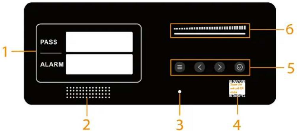
Table 4-1 Control panel description
| No. | Name Description | ||
| 1 | LED display | Two sets of 5-digit LED display.By default, the screen displays the number of passes and the number of alarms.After logging in, the screen displays the configuration menu cyclically.To know the menu order, see "4.2 Menu Description". | |
| 2 Buzzer Outputs sound alarm. | |||
| 3 | Indicator | Flashes green when the system is working. | |
| 4 | QR code | Scan the QR code on the actual device to get the user's manual. | |
| 5 Buttons |  | On the home screen, press≡to log in.When configuring parameters, press≡to save changes and move on to the next item. Hold the button for 5 s to cancel and exit. For setting all-zone sensitivity, resetting counter, automatic frequency search, factory reset, and diagnosis, you must press✓to save or confirm. For setting all-zone sensitivity, resetting counter, automatic frequency search, factory reset, and diagnosis, you must press✓to save or confirm. | |
 | Add up numbers or go to the previous item. | ||
 | Move to the next digit or next item. | ||
 | Save the current change.Hold the button for 5 s to shut down or start the host. | ||
| No. | Name Description |
| 6 Bar graph | Indicates the intensity of metal detection.The bar graph is comprised of 5 indicators. The indicator activity represents the level of metal detection intensity occurring within the archway. When 4 or 5 indicators are on, an alarm will be triggered. |
4.2 Menu Description
The function codes are displayed cyclically in the following order.
Table 4-2 Menu Order
| Order | Menu/Function/Parameter | Function Code | Range | Factory Default |
| 1 Program | PRO | 0-99 Middle | ||
| 2 Sensitivity | SENSI | 0-399 300 | ||
| 3 ReCount (Reset Counter) | rEcou | 0/1 0 | ||
| 4 Volume | Uo Iun | 0-9 8 | ||
| 5 Tone | tonE | 0-99 1 | ||
| 6 Alarm Time | AL-E | 0 s-9 s 1 s | ||
| 7 Frequency | FrE9u | 1-20 or auto frequency | 9 | |
| 8 L1-Zo (Left Zone 1) | L1-2o | 0-399 300 | ||
| 9 L2-Zo (Left Zone 2) | L2-2o | |||
| 10 | L3-Zo (Left Zone 3) | L3-2o | ||
| 11 R1-Zo (Rigth Zone 1) | R1-2o | |||
| 12 | R2-Zo (Rigth Zone 2) | R2-2o | ||
| 13 R3-Zo (Right Zone 3) | R3-2o | |||
| 14 Counter Mode | cound | 1/2 1 | ||
| 15 IR | IR | 0-3 1 | ||
| 16 Password | PASSU | 00000-99999 00000 | ||
| 17 Diagnosis | dioG | 0/1 0 | ||
| 18 Info | Info | — | Default IP: 192.168.1.108Version: Jxxxxxx ordxxxxxxVersion may differdepending on theactual product. | |
| 19 Default | DEFRU | 0/1 0 | ||
4.3 Login
You need to enter the password before going to the menu and configuring any parameter.
Step 1 Connect the power supply.
The detector starts and displays the number of passes and the number of alarms.

Do not stand in the walk-through during power-on to prevent IR sensor exception.

- The self-test routine automatically starts when the device is powered on, during which a power-on audio will go off for 2 seconds and the zone lights on the panels will be on from bottom to top.
- If the self-test discovers a problem other than a network connection exception, an error code will appear and audio and light alarms will go off for 2 seconds. For error code description, see "Error code description".
Step 2 Press ≡, and then enter the password.
Press < to increase the number from 0 to 9 or press > to reduce them, and then press to move to the next digit.
The default password is 000000.
Step 3 Press to confirm.
If the password is wrong, E is displayed.
4.4 Selecting Program
The detector is equipped with 100 programs to address a variety of security needs. Each program is designed with a set of sensitivity settings suitable for its application. After selecting a program, the sensitivity of each zone will change correspondingly.
Step 1 Log in to the menu, and ProG is displayed.
Step 2 Press < or > to navigate between the programs.
Step 3 Press ☑ to save or press ≡ to save and move to the next parameter.

Press ≡ for more than 2 s or after 60 s of inactivity, the system cancels the configuration and goes back to the home screen.
Table 4-3 Program sensitivity
| Program Code | Program | Default Sensitivity |
| CUSTo | Custom 0 | |
| Hi | High 395 | |
| CNi | Middle 300 | |
| Lo | Low 200 | |
| SL-01 | SL01-SL40 | 10-400 |
| P-01 | P01-P56 Predefined values |

- For the custom program, sensitivity value will be saved regardless of program change.
- For predefined programs, if you change any sensitivity value, the program will become a custom program while the original predefined sensitivity values keep the same.
Table 4-4 Program definition
| Program | Scenario | Program | Scenario |
| P-01 | Buildings1 | P-29 | Airport5 |
| P-02 | Buildings2 | P-30 | Airport6 |
| P-03 | Schools1 | P-31 | Railway Stations1 |
| P-04 | Schools2 | P-32 | Railway Stations2 |
| P-05 | Restaurants1 | P-33 | Bus Stations1 |
| P-06 | Restaurants2 | P-34 | Bus Stations2 |
| P-07 | Hotels1 | P-35 | Metro Stations1 |
| P-08 | Hotels2 | P-36 | Metro Stations2 |
| P-09 | Hospitals1 | P-37 | Stadiums1 |
| P-10 | Hospitals2 | P-38 | Stadiums2 |
| P-11 | Bar1 | P-39 | Critical infrastructures1 |
| P-12 | Bar2 | P-40 | Critical infrastructures2 |
| P-13 | Special Events1 | P-41 | Borders1 |
| P-14 | Special Events2 | P-42 | Borders2 |
| P-15 | Exhibitions1 | P-43 | Procuratorates1 |
| P-16 | Exhibitions2 | P-44 | Procuratorates2 |
| P-17 | Concert Halls1 | P-45 | Court House1 |
| P-18 | Concert Halls2 | P-46 | Court House2 |
| P-19 | Arenas1 | P-47 | Prisons1 |
| P-20 | Arenas2 | P-48 | Prisons2 |
| P-21 | Logistics1 | P-49 | Mail1 |
| P-22 | Logistics2 | P-50 | Mail2 |
| P-23 | Express1 | P-51 | Warehouse1 |
| P-24 | Express2 | P-52 | Warehouse2 |
| P-25 | Airport1 | P-53 | Mines1 |
| P-26 | Airport2 | P-54 | Mines2 |
| P-27 | Airport3 | P-55 | Power Station1 |
| P-28 | Airport4 | P-56 | Power Station2 |
4.5 Setting All-zone Sensitivity
At high sensitivity levels, small metal objects are easily detected. At low sensitivity settings, large metal objects are easily detected. This function supports quick setting of a same sensitivity value for
all zones. The value ranges from 0 to 399.
Keep in mind that the sensitivity should be set high enough so that the smallest forbidden object (depending on your security needs) can be detected. If you set it as 0, no alarm will be triggered.
Step 1 Log in to the menu, and then press ≡ until SENS is displayed.
Step 2 Press < or > to adjust the value, and then press √ to save.
The sensitivity of all zones will be changed correspondingly.

Press and hold < or > to make a 10-step adjustment.

- Press ≡ to move to the next parameter without saving the configuration.
- Press ≡ for more than 2 s or after 60 s of inactivity, the system cancels the configuration and goes back to the home screen.
4.6 Resetting Counter
A built-in and user resettable traffic counter records the number of passes and the number of alarms. You can reset the counter.
Step 1 Log in to the menu, and then keep pressing ≡ until rEcou is displayed.
Step 2 Press < or > to navigate to 1.
1 means to reset the counter, and 0 means not to reset the counter.
Step 3 Press to confirm.
DonE indicates that the counter is successfully reset. Both the number of passes and alarms become 0.

- Press ≡ to move to the next parameter without saving the configuration.
- Press ≡ for more than 2 s or after 60 s of inactivity, the system cancels the configuration and goes back to the home screen.
4.7 Adjusting Alarm Volume
The alarm volume ranges from 0 to 9. It is 8 by default. If you set it as 0, there will be no sound alarm.
Step 1 Log in to the menu, and then keep pressing ≡ until Uo lun is displayed.
Step 2 Press < or > to adjust the volume.
Step 3 Press ☑ to save or press ≡ to save and move to the next parameter.

Press ≡ for more than 2 s or after 60 s of inactivity, the system cancels the configuration and goes back to the home screen.
4.8 Changing Alarm Tone
A total of 99 tones are available. Select one that you prefer. Tone 1 is selected by default.
Step 1 Log in to the menu, and then keep pressing ≡ until tonE is displayed.
Step 2 Press < or > to navigate between the options.
Step 3 Press ☑ to save or press ≡ to save and move to the next parameter.

Press ≡ for more than 2 s or after 60 s of inactivity, the system cancels the configuration and goes back to the home screen.
4.9 Adjusting Alarm Time
Adjust the duration of sound and light alarm. It ranges from 0 s to 9 s. When it is set as 0, there will be no sound or light alarm.
Step 1 Log in to the menu, and then keep pressing ≡ until RL-E is displayed.
Step 2 Press < or > to navigate between the options.
Step 3 Press ☑ to save or press ≡ to save and move to the next parameter.

Press ≡ for more than 2 s or after 60 s of inactivity, the system cancels the configuration and goes back to the home screen.
4.10 Adjusting Frequency
For multiple walk-through metal detector operation, set each of them to a different frequency to reduce mutual interference. It can be adjusted from 0 to 20 or automatically search the ambient frequency.
Step 1 Log in to the menu, and then keep pressing ≡ until Fr-E9u is displayed.
Step 2 Press < or > to navigate between the options.
- Select a frequency from 1 to 20, and then press ☑ to save or press ≡ to save and move to the next parameter.
- Select AuFrE and then press √ and the detector starts to search the ambient frequency automatically with - scrolling from left to right.
After few seconds, DonE will be displayed, indicating it is successful.

Press ≡ to move to the next parameter without saving the configuration.
Press ≡ for more than 2 s or after 60 s of inactivity, the system cancels the configuration and goes back to the home screen.
4.11 Setting Each-zone Sensitivity
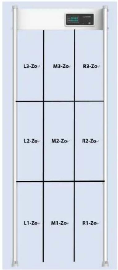
At high sensitivity levels, small metal objects are easily detected. At low sensitivity settings, large metal objects are easily detected. This function supports individually adjusting the sensitivity of the detector's zones. The detector contains 9 zones: 3 zones from bottom to top and 3 zones from left to right.
The sensitivity ranges from 0 to 399. Keep in mind that the sensitivity should be set high enough so that the smallest forbidden object (depending on your security needs) can be detected. If you set it as 0, there will be no alarms.
Step 1 Log in to the menu, and then keep pressing ≡ until L1-20 (Left Zone 1, followed by L2-Zo, L3-Zo, R1-Zo, R2-Zo, and R3-Zo) is displayed.

When you move to a zone, the corresponding zone light will be on indicating its position.
Step 2 Press < or > to adjust the value.

Press and hold < or > to make a 10-step adjustment.
Step 3 Press ☑ to save, or press ≡ to save and move to the next zone.

Press ≡ for more than 2 s or after 60 s of inactivity, the system cancels the configuration and goes back to the home screen.

For M1-Zo, M2-Zo, and M3-Zo, their sensitivity will be automatically adjusted according to the sensitivity of adjacent zones.
Figure 4-2 Detection zones
4.12 Setting Counter Mode
A built-in traffic counter records the number of people who pass through the detector. Two modes are available: entry+ exit+ or entry+ exit-.
Figure 4-3 Entry
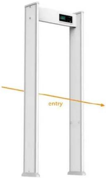

Going towards the side where the host is facing or where an operator stands represents an entry.
Step 1 Log in to the menu, and then keep pressing ≡ until couno is displayed.
Step 2 Press < or > to navigate between 1 and 2.
1 represents entry+ exit+, and 2 represents entry+ exit-.
Step 3 Press ☑ to save or press ≡ to save and move to the next parameter.

Press ≡ for more than 2 s or after 60 s of inactivity, the system cancels the configuration and goes back to the home screen.
4.13 Setting IR Mode
Infrared sensors have been designed to help prevent false alarms caused by nearby external moving metallic materials such as wheelchairs, elevators, persons possessing metal, and more, and when outdoors by wind causing the unit to rock and then alarm.
There are two groups of IR sensors and four modes.

The side where the host is facing is the front side, and the opposite is the rear side.
Table 4-5 IR modes
| No. Mode Note | |
| 0 Both off | When both groups are off, the detector may alarm under the above circumstances even when no one is passing through the detector. |
| 1 Both on | When both groups are on, the above circumstances will not cause the detector to alarm when no one is passing through the detector. |
| 2 Front on | If one or one group of sensors are broken, you can enable another sensor group, so that the detector and the counter can still work normally. |
| 3 Rear on |
Step 1 Log in to the menu, and then keep pressing ≡ until RA is displayed.
Step 2 Press < or > to navigate between 0, 1, 2 and 3.
Step 3 Press √ to save or press ≡ to save and move to the next parameter.

Press ≡ for more than 2 s or after 60 s of inactivity, the system cancels the configuration and goes back to the home screen.
4.14 Changing Password
Change the password regularly to keep the device safe.
Step 1 Log in to the menu, and then keep pressing ≡ until PASSU is displayed.
Step 2 Press < or > to set the number to 1, and then press √.
Step 3 Press < to increase the number from 0 to 9 or press > to reduce them, and then
press to move to the next digit.
Step 4 Press √ and the screen displays Conf.
Step 5 Enter the new password again and then press ☑ to confirm.
- indicates success.
- Indicates failure.

- Press ≡ to move to the next parameter without saving the configuration. - Press ≡ for more than 2 s or after 60 s of inactivity, the system cancels the configuration and goes back to the home screen.
4.15 Diagnosis
The self-test routine automatically starts when the detector is powered on. You can also manually test the system, including the network connection, IR sensors, panel connection, and sound and light alarm.

- The self-test routine automatically starts when the device is powered on, during which a power-on audio will go off for 2 seconds and the zone lights on the panels will be on from bottom to top.
- If the self-test discovers a problem other than a network connection exception, an error code will appear and audio and light alarms will go off for 2 seconds. For error code description, see "Error code description".
Procedure
Step 1 Log in to the menu, and then keep pressing ≡ until d:\oG is displayed.
Step 2 Press < or > to navigate to 1.
1 represents to diagnose and 0 represents not to diagnose.
Step 3 Press √, and the self-test starts, during which the zone lights will be on.
If the self test discovers a problem, an error code will appear and an audio alarm will go off for 2 seconds.

- Press ≡ to move to the next parameter without saving the configuration.
- Press ≡ for more than 2 s or after 60 s of inactivity, the system cancels the configuration and goes back to the home screen.
Result
Error code (example)
doo
E133
Table 4-6 Error code description
| Code | Description | Note |
| E | Error — | |
| First digit (1 in the example) | Network cable connection | 0: connected1: not connected |
| Second digit (3 in the example) | IR sensor status | 0: normal1: front sensor(s) exception2: rear sensor(s) exception3: front and rear sensors exception |
| Third digit (3 in the example) | Door panel connection | 0: normal1: left panel exception2: right panel exception3: exception of both panels |
4.16 Viewing IP and Version
View the IP and the software version of the detector.
Step 1 Log in to the menu, and then keep pressing ≡ until lnFo is displayed.
The screen displays the IP and version information in a loop.
The default IP is 192.168.1.108, and the version is a 6-letter string started with J or D which might differ depending on the actual product.

To change the detector IP, see "5.4 Changing IP".
Step 2 Press ≡ to move to the next parameter.
4.17 Factory Default
Restore the detector to factory default settings.
Step 1 Log in to the menu, and then keep pressing ≡ until DEFRU is displayed.
Step 2 Press < or > to navigate to 1.
1 means to restore to default settings, and 0 means not to restore.
Step 3 Press √, and then the detector will restart, displaying rE600

- Press ≡ to move to the next parameter without saving the configuration.
- Press ≡ for more than 2 s or after 60 s of inactivity, the system cancels the configuration and goes back to the home screen.
5 Upgrade and Changing IP
You can use ConfigTool to upgrade the detector software and change the detector IP.

Contact our overseas sales team to acquire ConfigTool.
5.1 Configuring Network
Before upgrading the detector, you need to connect your computer and the detector to the same local network first.
Step 1 Use a network cable to connect the host and your computer, so that the detector and the computer are on the same local network.
Step 2 Set the IP of the detector and the computer on the same network segment. For example, the IP of the detector is 192.168.1.108 by default, so you can set the IP of the computer as 192.168.1.1, the network mask as 255.255.255.0, and the default gateway as 192.168.1.2.
5.2 Searching for Detector
Search for the detector on ConfigTool.
Step 1 Open ConfigTool, and then select Modify IP > Search Setting.
Step 2 Enter the network segment of the detector in the Start IP box and End IP box.
Step 3 Enter the username and password (admin/admin by default).
Figure 5-1 Search for detector on ConfigTool
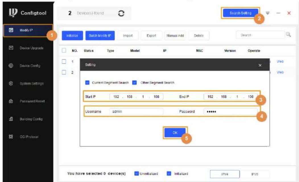
Step 4 Click OK.
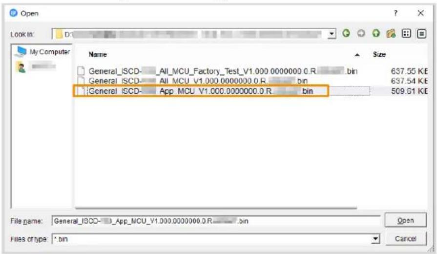
5.3 Upgrading Detector
Upload the program file to upgrade the detector.
Step 1 Click Device Upgrade.
Step 2 Click, select General_ISCD- xxx_APP_MCU_V1.000.000000.0R_xxxxxxfrom the
General_ISCD-xxx_V1.000.000000.0R_xxxxxx directory, and then click Open.
Figure 5-2 Select upgrade file
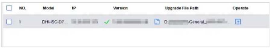
Step 3 Click ↑ to start upgrading.
After upgrade is complete, a notice dialog box will be displayed indicating the detector will be restarted. Then the detector restarts automatically.
A green tick is displayed after the upgrade is successful.
Figure 5-3 Upgrade completed
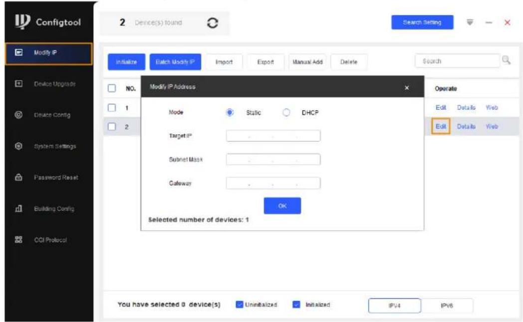
5.4 Changing IP
Change the detector IP with ConfigTool.
Step 1 Click Modify IP.
Step 2 On the device list, click Edit.
Step 3 Change the target IP, subnet mask, and gateway of the detector.
Figure 5-4 Change detector IP
6 FAQ
1. Deal with the replaced spare parts.
Contact our overseas service center to check whether you need to send back the spare parts.
2. The detector cannot start.
a. Check whether the power is switched on.
b. Check whether the host box is powered on.
c. Check whether the power cable is loose or broken.
d. Replace the host box.
3. The screen cannot display content after the detector starts.
a. Check whether the power is switched on.
b. Check whether the host box is powered on.
c. Check whether the cable between the detector panel and the host box is well connected.
d. Replace the host box.
4. The passed people cannot be counted (The indicator light cannot work normally, or the detector alarms without people passing).
a. Check whether both groups of IR are enabled. If not, set the IR mode to 1.
b. Goes to the diagnosis page, and check the error code.
c. Remove the host box and test it with the detector panels that can work normally. If the problem is still there, replace the host box; otherwise, replace detector panels.
5. There are false alarms.
a. Check whether the environment influences the detection rate of the detector. For example, check whether there is direct light to the infrared sensors, and whether there are large metals within 1 meter's range.
b. Adjust the frequency. Use the function of auto search frequency first. If the result is not good, adjust the frequency manually. To quickly set the suitable frequency, we recommend 3 levels for an adjustment. For example, when the current frequency is 3, adjust it to 6, and then check whether there are false alarms; if yes, adjust it to 9, and then check whether there are false alarms again. Repeat the operation until there is no false alarm.
c. Adjust the sensitivity to lower level.
d. Replace the host box for testing.
e. If the problem is still there, replace the detector panels.
6. No alarm is triggered when a person with carry-on metal is passing.
a. Set the sensitivity of each zone higher.
b. If no alarm is triggered with the highest sensitivity level, replace the host box for testing.
c. Check the alarm volume and alarm time, make sure the value is not 0.
d. If the problem is still there, replace the detector panels.
7. Alarm lights are not on.
a. Check whether the power supplies of the host and the detector panel are normal.
b. Check whether the ribbon cables of the alarm light are loose or broken.
c. Check the alarm time and make sure the value is not 0.
d. If the problem is still there, replace the panels.
8. No alarm is triggered in zones.
a. Set the sensitivity value higher.
b. Replace the host detector.
c. If the problem is still there, replace detector panels.
9. No alarm sound.
a. Check whether the alarm sound is disabled.
b. Check the alarm duration, make sure the value is not 0.
c. Replace the speaker.
10. There are big differences among the zone sensitivity values.
a. Configure the sensitivity values according to the actual situation of each zone.
b. If the problem is still there, replace detector panels.
11. Buttons on the host box cannot work normally.
a. Check whether buttons are in good contact.
b. If buttons are in good contact, replace the mainboard.
12. The remote controller cannot work normally.
a. Replace the batteries.
b. Check whether the buttons work normally.
c. Check whether the IR sensor on the host box is blocked or interfered.
13. The network of the host box is not successfully connected.
a. Check whether the network cable is well connected, and whether the detector IP and the default IP are in the same network segment.
b. Check whether the connection board and the cable are well connected, or whether they are broken.
c. Install the mainboard program again.
d. If the problem is still there, replace related accessories.
14. Forget Password.
a. Press and hold the reset button for more than 5 s to reset the password.
b. If failed, contact our overseas service center or service hotline.
15. Failed to connect the detector to platforms.
a. Check whether the detector connects to the same network segment as the platform.
b. Check whether the username and password are correct.
c. If you forget the password, press and hold the reset button to restore the detector.
Appendix 1 Cybersecurity Recommendations
Mandatory actions to be taken for basic device network security:
1. Use Strong Passwords
Please refer to the following suggestions to set passwords:
- The length should not be less than 8 characters.
- Include at least two types of characters; character types include upper and lower case letters, numbers and symbols.
- Do not contain the account name or the account name in reverse order.
- Do not use continuous characters, such as 123, abc, etc.
- Do not use overlapped characters, such as 111, aaa, etc.
2. Update Firmware and Client Software in Time
- According to the standard procedure in Tech-industry, we recommend to keep your device (such as NVR, DVR, IP camera, etc.) firmware up-to-date to ensure the system is equipped with the latest security patches and fixes. When the device is connected to the public network, it is recommended to enable the "auto-check for updates" function to obtain timely information of firmware updates released by the manufacturer.
- We suggest that you download and use the latest version of client software.
"Nice to have" recommendations to improve your device network security:
1. Physical Protection
We suggest that you perform physical protection to device, especially storage devices. For example, place the device in a special computer room and cabinet, and implement well-done access control permission and key management to prevent unauthorized personnel from carrying out physical contacts such as damaging hardware, unauthorized connection of removable device (such as USB flash disk, serial port), etc.
2. Change Passwords Regularly
We suggest that you change passwords regularly to reduce the risk of being guessed or cracked.
3. Set and Update Passwords Reset Information Timely
The device supports password reset function. Please set up related information for password reset in time, including the end user's mailbox and password protection questions. If the information changes, please modify it in time. When setting password protection questions, it is suggested not to use those that can be easily guessed.
4. Enable Account Lock
The account lock feature is enabled by default, and we recommend you to keep it on to guarantee the account security. If an attacker attempts to log in with the wrong password several times, the corresponding account and the source IP address will be locked.
5. Change Default HTTP and Other Service Ports
We suggest you to change default HTTP and other service ports into any set of numbers between 1024–65535, reducing the risk of outsiders being able to guess which ports you are using.
6. Enable HTTPS
We suggest you to enable HTTPS, so that you visit Web service through a secure communication channel.
7. MAC Address Binding
We recommend you to bind the IP and MAC address of the gateway to the device, thus reducing the risk of ARP spoofing.
8. Assign Accounts and Privileges Reasonably
According to business and management requirements, reasonably add users and assign a minimum set of permissions to them.
9. Disable Unnecessary Services and Choose Secure Modes
If not needed, it is recommended to turn off some services such as SNMP, SMTP, UPnP, etc., to reduce risks.
If necessary, it is highly recommended that you use safe modes, including but not limited to the following services:
- SNMP: Choose SNMP v3, and set up strong encryption passwords and authentication passwords.
- SMTP: Choose TLS to access mailbox server.
- FTP: Choose SFTP, and set up strong passwords.
- AP hotspot: Choose WPA2-PSK encryption mode, and set up strong passwords.
10. Audio and Video Encrypted Transmission
If your audio and video data contents are very important or sensitive, we recommend that you use encrypted transmission function, to reduce the risk of audio and video data being stolen during transmission.
Reminder: encrypted transmission will cause some loss in transmission efficiency.
11. Secure Auditing
- Check online users: we suggest that you check online users regularly to see if the device is logged in without authorization.
- Check device log: By viewing the logs, you can know the IP addresses that were used to log in to your devices and their key operations.
12. Network Log
Due to the limited storage capacity of the device, the stored log is limited. If you need to save the log for a long time, it is recommended that you enable the network log function to ensure that the critical logs are synchronized to the network log server for tracing.
13. Construct a Safe Network Environment
In order to better ensure the safety of device and reduce potential cyber risks, we recommend:
- Disable the port mapping function of the router to avoid direct access to the intranet devices from external network.
- The network should be partitioned and isolated according to the actual network needs. If there are no communication requirements between two sub networks, it is suggested to use VLAN, network GAP and other technologies to partition the network, so as to achieve the network isolation effect.
- Establish the 802.1x access authentication system to reduce the risk of unauthorized access to private networks.
- Enable IP/MAC address filtering function to limit the range of hosts allowed to access the device.
- Walk-through Metal Detector
- Foreword
- General
- Safety Instructions
- Revision History
- Privacy Protection Notice
- About the Manual
- Important Safeguards and Warnings
- Transportation Requirements
- Storage Requirements
- Installation Requirements
- Operation Requirements
- Maintenance Requirements
- WARNING
- Table of Contents
- Foreword....
- Important Safeguards and Warnings....III
- Overview....1
- Structure 2
- Installation....4
- Configuration 9
- Upgrade and Changing IP 21
- Overview
- Introduction
- Technical Advantages
- Structure
- Dimensions
- Ports
- Installation
- Checklist
- Environment Requirements
- Installing Detector
- Multiple Walk-through Site Installation
- Configuration
- Controls and Displays
- Menu Description
- Login
- Selecting Program
- Setting All-zone Sensitivity
- Resetting Counter
- Adjusting Alarm Volume
- Changing Alarm Tone
- Adjusting Alarm Time
- Adjusting Frequency
- Setting Each-zone Sensitivity
- Setting Counter Mode
- Setting IR Mode
- Changing Password
- Diagnosis
- Procedure
- Result
- Viewing IP and Version
- Factory Default
- Upgrade and Changing IP
- Configuring Network
- Searching for Detector
- Upgrading Detector
- Changing IP
- FAQ
- Deal with the replaced spare parts.
- The detector cannot start.
- The screen cannot display content after the detector starts.
- The passed people cannot be counted (The indicator light cannot work normally, or the detector alarms without people passing).
- There are false alarms.
- No alarm is triggered when a person with carry-on metal is passing.
- Alarm lights are not on.
- No alarm is triggered in zones.
- No alarm sound.
- There are big differences among the zone sensitivity values.
- Buttons on the host box cannot work normally.
- The remote controller cannot work normally.
- The network of the host box is not successfully connected.
- Forget Password.
- Failed to connect the detector to platforms.
- Appendix 1 Cybersecurity Recommendations
- Mandatory actions to be taken for basic device network security:
- Use Strong Passwords
- Update Firmware and Client Software in Time
- "Nice to have" recommendations to improve your device network security:
- Physical Protection
- Change Passwords Regularly
- Set and Update Passwords Reset Information Timely
- Enable Account Lock
- Change Default HTTP and Other Service Ports
- Enable HTTPS
- MAC Address Binding
- Assign Accounts and Privileges Reasonably
- Disable Unnecessary Services and Choose Secure Modes
- Audio and Video Encrypted Transmission
- Secure Auditing
- Network Log
- Construct a Safe Network Environment
Brand : Dahua Technology
Model : ISC-D109L
Category : Detector