Tungsten Smart-Heat BH0510005 - Heating Bromic - Free user manual and instructions
Find the device manual for free Tungsten Smart-Heat BH0510005 Bromic in PDF.


| Product Type | Electric Infrared Patio Heater |
| Brand | Bromic |
| Model | Tungsten Smart-Heat BH0510005 |
| Heating Technology | Quartz Tungsten Infrared |
| Power Source | Electric (Hardwired) |
| Power Rating | 1500W / 2000W (Selectable) |
| Voltage | 120V or 240V (Check local model) |
| Heat Output | Up to 6,800 BTU/h |
| Heating Coverage | Up to 100 sq ft (9.3 m²) |
| Dimensions (H x W x D) | 28.7 x 10.6 x 7.5 in (73 x 27 x 19 cm) |
| Weight | 13.2 lbs (6 kg) |
| Mounting Type | Wall-mounted or Ceiling-mounted |
| Smart Control | Yes – Wi-Fi enabled, Smart-Heat app control |
| Remote Control | Included (handheld) |
| Heat Settings | Low / Medium / High (or variable) |
| Safety Features | Tip-over protection, Overheat protection, Cool-touch housing |
| Weather Resistance | IP65 rated – Suitable for outdoor use |
| Housing Material | Aluminum with stainless steel grille |
| Color | Silver / Black (depending on variant) |
| Noise Level | Silent operation |
| Compliance/Certifications | ETL, CSA, UL (varies by region) |
| Warranty | Limited 2-year warranty |
| Included Accessories | Mounting bracket, remote control, user manual |
| Maintenance | Wipe with damp cloth; do not use abrasive cleaners |
| Spare Parts Availability | Contact Bromic customer service |
Frequently Asked Questions - Tungsten Smart-Heat BH0510005 Bromic
User questions about Tungsten Smart-Heat BH0510005 Bromic
0 question about this device. Answer the ones you know or ask your own.
Ask a new question about this device
Download the instructions for your Heating in PDF format for free! Find your manual Tungsten Smart-Heat BH0510005 - Bromic and take your electronic device back in hand. On this page are published all the documents necessary for the use of your device. Tungsten Smart-Heat BH0510005 by Bromic.
USER MANUAL Tungsten Smart-Heat BH0510005 Bromic
INSTALLATION, INSTRUCTION AND SERVICE MANUAL
SUITABLE FOR GAS RADIANT HEATER MODELS: TUNGSTEN SMART-HEAT™

WARNING
Do not store or use petrol or other flammable vapor and liquids in the vicinity of this or any other appliance.
An LP-cylinder not connected for use shall not be stored in the vicinity of this or any other appliance.

NING: Improper installation,
adjustment, alteration, service or maintenance can cause property damage, injury or death. Read the installation, operating and maintenance instructions thoroughly before installing or servicing this equipment.

DANGER
If you smell gas:
- Shut off gas to the appliance
- Extinguish any open flame
- If odour continues, keep away from the appliance and immediately call your gas supplier or fire department.

WARNING: For Outdoor Use Only.

This manual contains important information about the assembly, operation, and maintenance of TUNGSTEN Smart-Heat™ Heaters. Please pay close attention to the important safety information shown throughout this instruction manual. Any safety information will be accompanied by the following safety alert symbols:
⚠️DANGER, ⚠️WARNING, ⚠️IMPORTANT
READ THIS MANUAL CAREFULLY before installing or servicing this product
- Installation and repair should be done by a qualified service person.
- The heater should be inspected before use and at least annually by a qualified service person.
- Improper installation, operation, or maintenance can result indeath, severe injury, or property damage.
- This manual must be left with the consumer following installation & the consumer must retain them for future reference.

Head Office: 13223 Black Mountain Rd. Suite 1305 San Diego California 92129 United States
Telephone: 1 800 301 1293 Fax: +61 2 9748 4289
Email: info@bromicheating.com Web: www.bromicheating.com
Note: Bromic Heating Pty Ltd reserves the right to make changes to specifications, parts, components and equipment without prior notification. This Installation, operation and service manual may not be reproduced in any form without prior written consent from Bromic Heating Pty Ltd.
CONTENTS
IMPORTANT NOTES & WARNINGS 4
PRODUCT OVERVIEW 5
PRODUCT DESCRIPTION 5
SPECIFICATIONS 5
GENERAL INFORMATION 6
PRODUCT FEATURES 6
INSTALLATION REQUIREMENTS 7-8
GAS REQUIREMENTS 7
INSTALLATION CLEARANCES 8
INSTALLATION INSTRUCTIONS 9-20
HEATER INSTALLATION INSTRUCTIONS 9-19
LEAKAGE TEST 20
OPERATING INSTRUCTIONS 21
TURNING THE APPLIANCE ON 21
TURNING THE APPLIANCE OFF 21
MAINTENANCE AND SERVICING 22
TROUBLE SHOOTING 23
APPENDIX A 24 - 26
IMPORTANT NOTES AND WARNINGS

WARNING
Failure to follow the warnings and instructions in this manual could result in severe personal injury, death or property damage.
- Installation and repair should be done by a qualified service person. The heater should be inspected before use and at least annually by a qualified service person.
- Do not use or store flammable materials near this appliance
- Do not spray aerosols or flammable materials in the vaccinity of this appliance while it is in operation
- Any guard or other protective device removed for servicing (conducted by an authorised person) must be replaced before operating the heater.
- Children and adults should be alerted to the hazards of high surface temperatures and should stay away to avoid burns or clothing ignition.
- Children should be carefully supervised when they are in the area of the heater.
- Clothing or other flammable materials should not be hung from the heater or placed on or near the heater.
- Do not perform maintenance until heater has been turned off, and heater temperature has cooled to room temperature.
- Do not expose the burner to water or moisture. The appliance must be protected from rain.
- Do not use the heater if any of these parts are exposed to water until the appliance is inspected or repaired by an authorised service person.
- The installer is to ensure that the requirements of the local authority, local gas fitting regulations, municipal building codes, and any other relevant statutory regulations are carried out.
- Certain materials or items, when stored under or near the appliance, will be subjected to radiant heat and could be seriously damaged.
- The whole gas system, hose assembly, regulator, pipes, and burner should be inspected for damage and leaks before each use and at least annually by an authorized person for the life of the heater.
- The hose assembly must be replaced prior to the appliance being put into operation if there is evidence of excessive abrasion or wear, or if the hose is damaged. The replacement hose must be purchased from Bromic Heating Pty Ltd.
- All leak tests should be done with a soap solution. Never use an open flame to check for leaks.
- Do not use the heater until all connections have been leak tested by an authorised person.
- This radiant heater is NOT intended to be installed on recreational vehicles and/or boats.
- Improper installation, adjustment, or alteration can cause personal injury, property damage, or even death.
- Do not attempt to alter the unit in any manner.
- Do not paint any surface of the heater or top canopy reflector.
- Burner and circulation air passageways of the heater must be kept clean. Frequent cleaning may be required as necessary.
- Turn Gas Supply off when not in use.
- Check the heater immediately if any of the following occurs: »The heater does not reach temperature.
»The burner makes popping noise during use (a slight noise is normal when the burner is ignited or extinguished). - This appliance is not intended for use by young or infirm persons unless they have been adequately supervised by a
responsible person to ensure that they can use the appliance safely.
- Check for damage to the appliance regularly. If damage to the appliance is suspected, discontinue use immediately and contact the supplier or qualified person for repair.
- Avoid inhaling fumes emitted from the heater's first use. Smoke and odour from the burning of oils used in manufacturing will appear. Both the smoke and odour will dissipate after approximately 30 minutes.
- The pressure regulator and hose assembly supplied with the appliance must be used. Replacement regulator and hose assemblies must be purchased from Bromic Heating Pty Ltd.
- Storage of an appliance indoors is permissible only if the cylinder is disconnected and removed from the appliance.
- A cylinder must be stored outdoors in a well-ventilated area out of the reach of children. A disconnected cylinder must have dust caps tightly installed and must not be stored in a building, garage or any other enclosed area.
- Do not store a spare LP-gas cylinder under or near this appliance;
- Never fill the cylinder beyond 80% full
PRODUCT DESCRIPTION
The TUNGSTEN Gas Radiant Heater is designed to provide effective outdoor heating to both commercial and residential premises whilst offering an appealing design.
The heater incorporates a pivoting head and adjustable heat output for precise heat control. The heater has been designed to withstand the rigors of the outdoors.
SPECIFICATIONS
| TUNGSTEN Smart-HeatTM | |
| Ignition 1.5V repetitive spark ignitor | |
| Manufactured by BROMIC PTY LTD | |
| ETL approval number 4009079 | |
| Gas consumption 21,304 BTU - | 38,500 BTU |
| Gas Type Propane Gas (LPG) only | |
| Gas Supply 20Lb (9kg) LP- Gas | Cylinder |
| Injector size 0.85mm | |
| Weight 56Kg - 123.5lB | |
| Safety features Flame failure device, anti-tilt switch | |
| Gas supply pressure Min 11”wc – Max 14”wc | |
TUNGSTEN SMART-HEAT™ HEATER DIMENSIONAL DETAILS


IMPORTANT
This appliance is to be protected from rain. Install under a protective cover.
This appliance shall only be used in an above ground, open-air situation with sufficient natural ventilation. The heater must not be operated in any stagnant areas and should be positioned where any potential gas leakage and products of combustion are rapidly dispersed by wind and natural convection.
PRODUCT OVERVIEW CONTINUED...
GENERAL INFORMATION
The TUNGSTEN Gas Patio Heaters are suitable for outdoor spaces. In addition to the installation Instructions provided, authorized installers must abide by local codes, or in the absence of local codes, with the National Fuel Gas Code, ANSI Z223.1/NFPA 54, Natural Gas and Propane Installation Code, CSA B149.1, or Propane Storage and Handling Code, B149.2. Please note that these standards are subject to change.
PRODUCT FEATURES
TUNGSTEN Gas Patio Heaters are revolutionizing the outdoor heating industry by introducing ground breaking benefits never seen before in traditional gas or electric heaters. TUNGSTEN heaters have set the industry benchmark with stylish good looks and world-first innovation.
TUNGSTEN heaters excel in the areas of:
- Aesthetic appeal
- Innovation
- Performance
- Flexibility
- Cost effectiveness
For more detailed product information, visit www.bromicheating.com

IMPORTANT
Installation and repair should be done by a qualified service person. The heater should be inspected before use and at least annually by a qualified service person.
This appliance shall only be used in above ground open-air situations with:
- natural ventilation
• without stagnant areas - where gas leakage and products of combustion are rapidly dispersed by wind and natural convection
Any enclosure in which the appliance is used shall comply with one of the following:
- An enclosure with walls on all sides, but at least one permanent opening at ground level (ref. Appendix A, Example 1)
- Within a partial enclosure that includes an overhead cover and no more than two walls (ref. Appendix A, Example 2)
-
Within a partial enclosure that includes an overhead cover and more than two walls, the following shall apply:
-
At least 25% of the total wall area is completely open (ref. Appendix A, Example 4), and
- At least 30% of the remaining wall area is open and unrestricted (ref. Appendix A, Example 4)
Note: The definition of outdoors is an above ground open-air situation with natural ventilation, without stagnant areas, where gas leakage and products of combustion are rapidly dispersed by wind and natural convection.
GAS REQUIREMENTS
• Use Propane (LPG) gas cylinder only
- The approved manifold pressure to the appliance is 10" W.C.
- The MIN inlet pressure to the appliance is 11" W.C
- The MAX inlet pressure to the appliance is 14" W.C
IMPORTANT
• The LPG gas cylinder must be:
- Constructed and marked in accordance with the Specifications for LP-gas cylinders of the U.S. Department Transportation (DOT); or the Standard for Cylinders, Spheres and Tubes for Transportation of Dangerous Goods and Commission, CAN/CSA-B339, as applicable;
- Provided with a listed overfilling prevention device; and
- Provided with a cylinder connection device compatible with the connection for the appliance.
- Cylinder must have include a collar to protect the cylinder valve
INSTALLATION REQUIREMENTS CONTINUED...
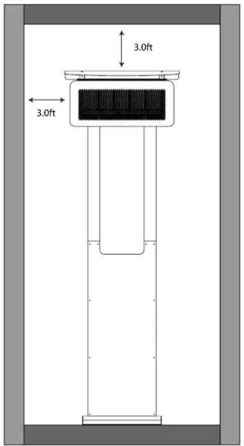
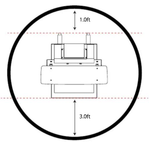
LOCATION CLEARANCES
When selecting the location for the TUNGSTEN Gas Patio Heater, the following clearances should be followed.
Care should be taken to ensure that the heater is not installed:
- Where heat/ignition can cause damage to gas cylinders/lines
• Near other combustible materials
• In open locations subject to rain
Note: Heater should be installed in such a way so as to allow adequate;
- Clearance around air openings to combustion chamber
- Clearance from combustible material
- Provisions for accessibility and clearance for combustion and ventilating air supply.

IMPORTANT
This appliance must only be used in a well ventilated area.
When selecting the installation location for the Tungsten Smart-Heat Portable, the following clearances should be followed.
INSTALLATION INSTRUCTIONS
CONTENTS PACKED IN (2) BOXES
Box 1 Contents

Head Assembly
AAA Battery
Box 2 Contents

Base Assembly

Front Assembly

Rear Arm Assembly x 2
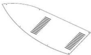
Side Panels x 2
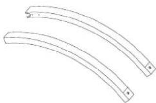
Top Arms x 2
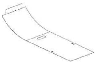
Rear Cover
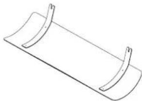
Top Flame Deflector

Regulator
INSTALLATION INSTRUCTIONS CONTINUED...
Supplied Fasteners
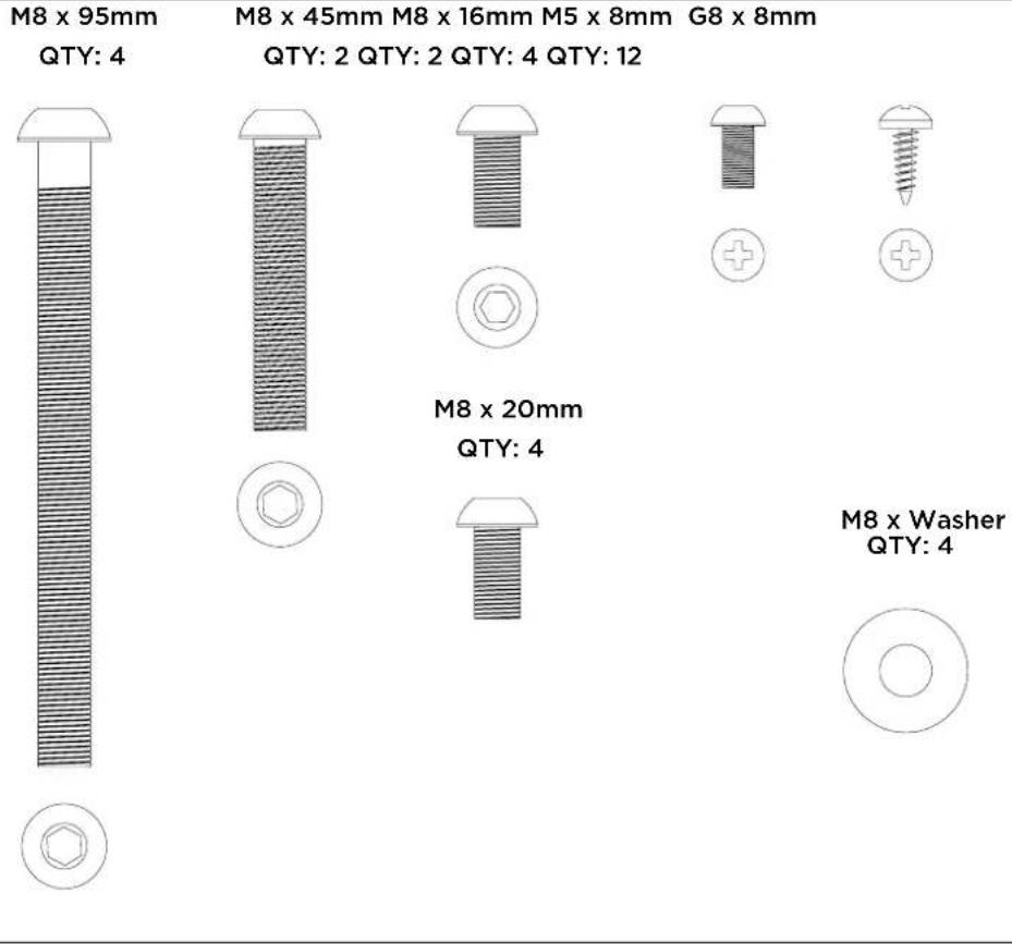
Supplied Tools

Tools Not Included
Phillips head screw driver and Spray Bottle
INSTALLATION INSTRUCTIONS CONTINUED...
STEP 1:
Unpack boxes and place all items on a non abrasive surface.
STEP 2:
Fasten rear arms to base using 2 x M8 20mm screws and the supplied M8 Hex Key.


STEP 3:
Position front assembly and fasten using 2 x M8 20mm screws using supplied M8 Hex Key.


INSTALLATION INSTRUCTIONS CONTINUED...
STEP 4:
Secure the rear arms to front assembly using 2 x M8 x 16mm screws and supplied M8 Hex Key.


STEP 5:
Secure the side panels to frame using 12 x G8 screws - A Phillips screw driver is required for this step. Repeat for opposite side.


INSTALLATION INSTRUCTIONS CONTINUED...
STEP 6:
Slide top arms over front assembly slip joints - Ensure top screw holes are faced inwards.
Secure the front panel to top arms using 4 x M5 screws and supplied M5 Hex Key.
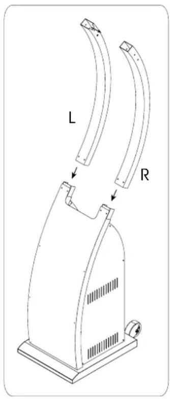

* Note: The joint between the lower and upper arms is firm to ensure` rigidily and stability of the product. To engage slowly lever the two sections together using some force and push down fully
STEP 7:
Secure the top arms to lower arm slip joint using 2 x M8 x45 screws and supplied M8 Hex Key.


INSTALLATION INSTRUCTIONS CONTINUED...
STEP 8:
Lay both heater head and stand on a non abrasive surface as shown. Two people are required for this step.

NON ABRASIVE SURFACE
STEP 9:
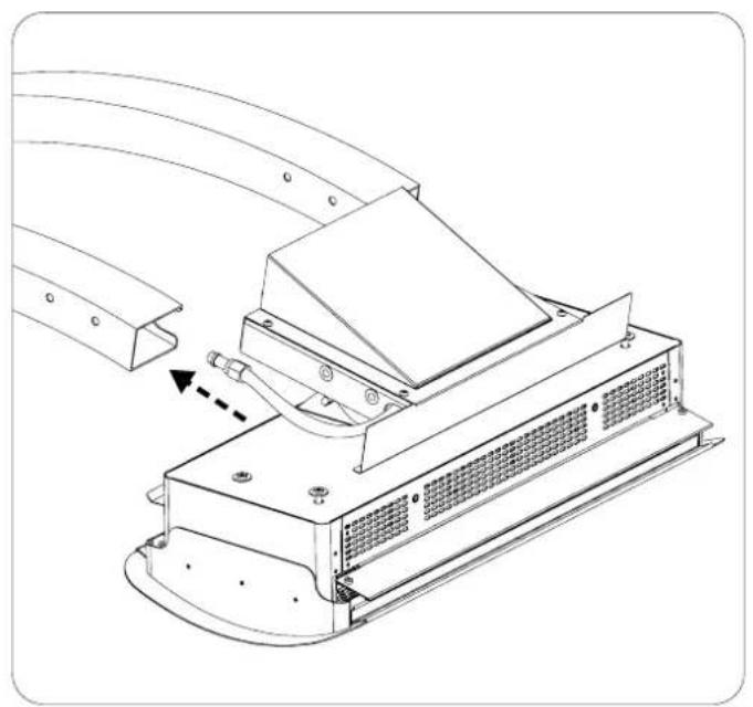
Feed gas hose through arm slot and push through until it reaches slot in bottom arm. Keep feeding hose until all slack is taken up.

INSTALLATION INSTRUCTIONS CONTINUED...
STEP 10:
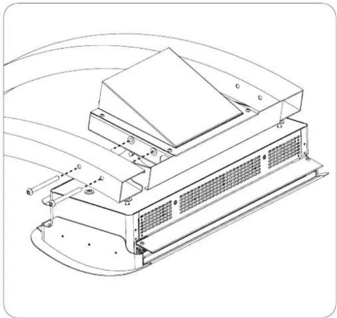
Secure the heater head to arms using 4 x M8 screws and supplied washers with M8 Hex Key.
STEP 13:
Return heater to upright position. Two people are required for this step.

NON ABRASIVE SURFACE
INSTALLATION INSTRUCTIONS CONTINUED...
STEP 14:
Screw regulator assembly to gas bottle.
STEP 15:
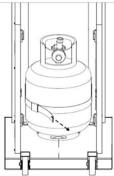
Place gas bottle into lower enclosure and fasten strap tightly.

STEP 16:
Pull sleeve back on regulator connector, insert hose fitting & release sleeve on regulator connector.
STEP 17:
Lower gas bottle bracket into position.


INSTALLATION INSTRUCTIONS CONTINUED...
STEP 18:
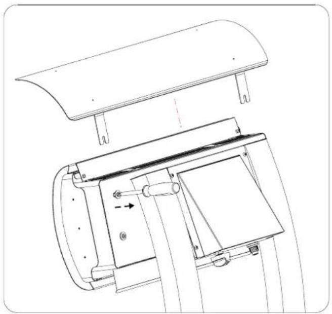
Secure deflector to heater by loosening the two screws and secure brackets underneath washers.
Re-tighten screws to original position using screw driver.

STEP 19:
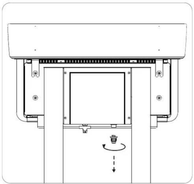
Unscrew igniter cap. Insert supplied AAA battery into cap and re-screw to original position

STEP 20:
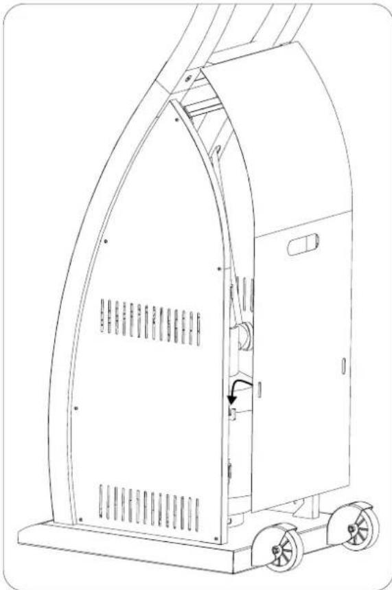
Perform Gas leakage test as shown on page 20
INSTALLATION INSTRUCTIONS CONTINUED...
STEP 21:
The back cover is secured by magnets. Firstly position slots in back cover over the two hooks then lower cover to allow magnets to catch
Adjusting the heater head angle
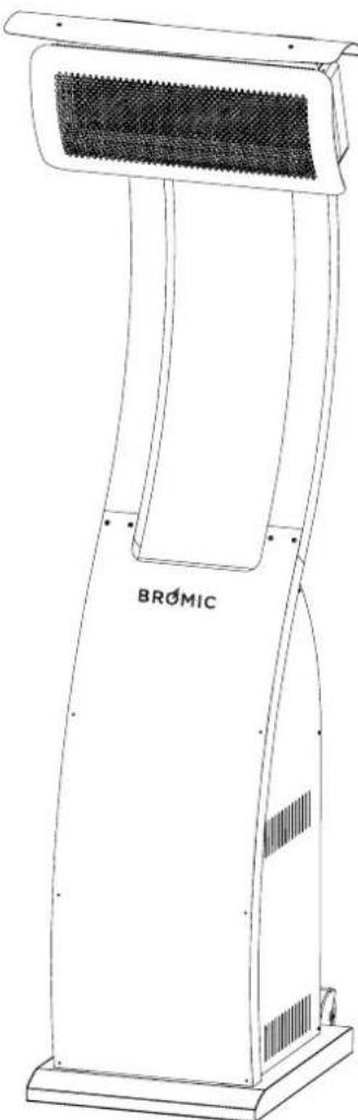
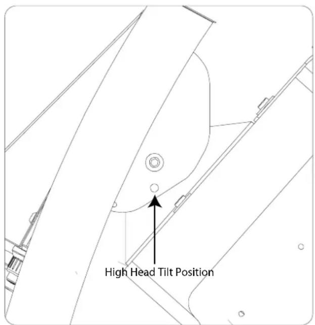
CAUTION: ONLY ADJUST THE HEATER HEAD ANGLE PRIOR TO OPERATION. ADJUSTING WHILST UNIT IS IN OPERATION OR POST OPERATION CAN CAUSE SERIOUS BURNS

To set heater head angle at high position, manually push heater head up to align hole then insert slip pin.
To set heater head angle at low position, remove slip pin & allow heater head to rest in low position. Slip pin does not need to be inserted.
LEAK TEST
Gas connections on heater are leak tested at the factory prior to shipment. A complete gas leak test must also be performed after assembly before operating the heater due to possible damage occurring during transportation.
- Never leak test while smoking.
- The heater must be checked with a full gas cylinder.
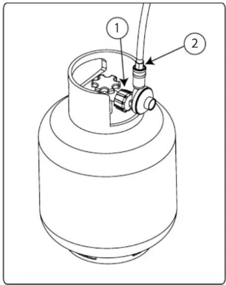
- Ensure connection all 3 connections illustrated below are connected correctly & tight.
- Make sure the control knob is in the OFF position.
-
Make a mild soapy water solution. The soapy solution can be applied with a spray bottle, or soft cloth.
-
Turn on the gas supply at the gas cylinder.
- Apply the soapy water solution to the 3 connections illustrated below.
- To check connection #3 the gas control knob must be pressed in to open the gas valve.
- If bubbles appear at any of the connections, there is a gas leak.
- If a gas leak is detected, turn off the gas supply. Tighten any leaking fittings, and repeat process described above.
- If soap bubbles still appear (gas is still leaking), turn off the gas supply at the cylinder, disconnect the regulator from the gas cylinder, and contact the store of purchase for assistance and advice.
- If gas connections are gas tight, the heater is ready to be used.

OPERATING INSTRUCTIONS
TURNING THE APPLIANCE ON
- Ensure that installation has been carried out in accordance with the manufacturers instructions outlined in this document.
- Test the spark ignite button is working correctly by pressing the button and observing sparks at the ignition rods at the front of the heater. If sparks are not observed do not proceed with turning appliance on. Contact the store of purchase for assistance and advice.

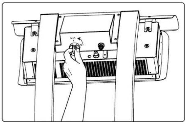
- Push in and hold control knob whilst simultaneously pressing the spark ignite button. Continue to hold in the controls for 10 seconds for ignition to complete.
Release the controls. If the heater has not ignited wait 5 minutes and then repeat Step 5.

TURNING THE APPLIANCE OFF
- Press and turn the control knob to "OFF" position to stop the supply of gas to the burner. The tiles should change colour from red to black.

WARNING
Do not turn the heater on with people standing in front of heater. Heater must be turned on while standing behind the heater.
WARNING
Improper lighting procedures can cause personal injury, property damage, or even death.
- Turn ON the gas supply at the LPG storage bottle.
- Turn on gas control knob to maximum setting
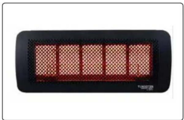
- When appliance is correctly turned on the tiles will start to glow red.
- Turn OFF the gas supply at the LPG storage bottle.

MAINTENANCE AND SERVICING
It is important that regular maintenance is carried out on the heater to maintain efficient operation. All maintenance should be carried out ONLY by authorized service personnel. Inspect and clean at least every six months or more frequently in adverse conditions.
Never obstruct the flow of combustion and ventilation air. Always keep the appliance area clear and free from combustible materials, gasoline and other flammable vapors and liquids. Do not clean heater with cleaners that are combustible or corrosive.
REGULAR SERVICE REQUIREMENTS
- The whole gas system, hose assembly, regulator, pipes, and burner should be inspected for damage and leaks before each use and at least annually by an authorized person for the life of the heater. To check the gas hose within the mounting arm, disassemble heater by reversing the installation instructions as outlined in installation section of this manual. The hose assembly must be replaced prior to the appliance being put into operation if there is evidence of excessive abrasion or wear, or if the hose is damaged. The replacement hose must be purchased from Bromic Heating Pty Ltd.
2. VISUALLY CHECK BURNER FLAMES.
During heaters function visually check that all burners are alight and glowing hot. This can be done by observing the red glow through the translucent face, or by peering down the product combustion passageway. Note: A slight variation in colour is to be expected.
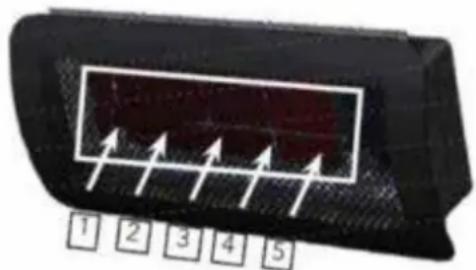
- Clean burners: Burners can be cleaned by directing compressed air (max20PSI) at outlet ports. Avoid directing air at gasket material between ceramic tile and burner cup.
- Clean manifold and injectors: Undo gas hose from gas valve outlet (heater should be switched off) and inject compressed air (max20PSI) down the inlet fittings.
- Clean dust and foreign matter from inside of heater housing: Open up rear housing and clear dust using compressed air (max20PSI) and a damp cloth.
- Remove debris, spider and insect nests from, control compartment, burner and circulation air passageways of the heater with heavy-duty pipe cleaner or compressed air to keep appliance clean and safe for use. Never clear ports or other openings with toothpicks or other articles that will break and block the ports.
- In a salt-air environment, such as near an ocean, corrosion occurs more quickly than normal. Remove salt spray from the heater immediately to prolong heater life. Check frequently for corroded areas and repair them promptly.
- The exterior components of the heater are constructed from stainless steel, and high temperature black paint.
- Over the life of the heater internal non-painted parts
may slightly discolour from high temperatures emitted by the heater. This is a normal occurrence and does not affect the operation of the appliance.
- Replacement parts can be purchased to restore the heater to its original appearance from Bromic Heating Pty Ltd.
IMPORTANT
Installation and repair should be done by a qualified service person.
The heater should be inspected before use and at least annually by a qualified service person.
More frequent cleaning may be required as necessary. It is imperative that control compartment, burners and circulating air passageways of the heater be kept clean.
IMPORTANT
Do not apply any additional surface coating to the heater under any circumstances. Use of additional coating other than those applied during manufacture could result in hazardous reactions such as toxic fumes or fires. Additional coatings will void the warranty.
TROUBLESHOOTING
| Problem Possible cause | What you can do(if these do not work, contact an authorised technician) | What ONLY an authorised service technician can do | |
| Burner will not light | Gas valve may be OFFTank fuel emptyOpening blockedLoose connectionsLow gas pressureThermocouple badNot in correct location | Turn the gas valve ONCheck all fittingsReplace cylinder with a new cylinder | Refill LPG tankRemove and cleanReplace thermocouple |
| Burner will not stay on | Loose connectionsThermocouple badGas leak in lineLack of fuel pressureTank near empty | Tighten connectionsCheck connections | Clean dirty areaReplace thermocoupleRefill LPG tank. |
| Burner flame is low | Supply hose is bent or twisted | Straighten hose and perform leak test on hose | |
| Emitter glows uneven | Low gas pressureBase is not on a level surface | Replace cylinder with a new cylinderPlace heater on a level surface | |
| Thick black smoke | Blockage in burner Turn off | the heater and let it cool. | Remove blockage and clear burner inside and outside |
| Carbon build-up | Dirt or film on reflector and flame screen | Clean reflector and flame screen | |
APPENDIX A
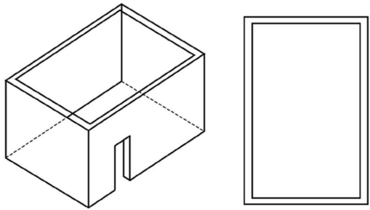
OUTDOOR AREA-EXAMPLE 1


OUTDOOR AREA-EXAMPLE 2

OUTDOOR AREA-EXAMPLE 3
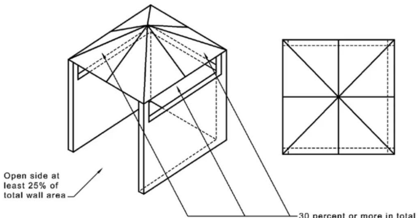

-30 percent or more in total of the remaining wall area is open and unrestricted
OUTDOOR AREA-EXAMPLE 4
APPENDIX A CONTINUED...

OUTDOOR AREA-EXAMPLE 5
- INSTALLATION, INSTRUCTION AND SERVICE MANUAL
- CONTENTS
- IMPORTANT NOTES & WARNINGS 4
- PRODUCT OVERVIEW 5
- INSTALLATION REQUIREMENTS 7-8
- INSTALLATION INSTRUCTIONS 9-20
- OPERATING INSTRUCTIONS 21
- MAINTENANCE AND SERVICING 22
- TROUBLE SHOOTING 23
- APPENDIX A 24 - 26
- IMPORTANT NOTES AND WARNINGS
- WARNING
- PRODUCT DESCRIPTION
- IMPORTANT
- PRODUCT OVERVIEW CONTINUED
- GENERAL INFORMATION
- PRODUCT FEATURES
- GAS REQUIREMENTS
- INSTALLATION REQUIREMENTS CONTINUED
- LOCATION CLEARANCES
- INSTALLATION INSTRUCTIONS
- CONTENTS PACKED IN (2) BOXES
- INSTALLATION INSTRUCTIONS CONTINUED
- STEP 1
- STEP 2
- STEP 3
- STEP 4
- STEP 5
- STEP 6
- STEP 7
- STEP 8
- STEP 9
- STEP 18
- STEP 19
- STEP 20
- STEP 21
- ADJUSTING THE HEATER HEAD ANGLE
- LEAK TEST
- OPERATING INSTRUCTIONS
- TURNING THE APPLIANCE ON
- TURNING THE APPLIANCE OFF
- MAINTENANCE AND SERVICING
- REGULAR SERVICE REQUIREMENTS
- VISUALLY CHECK BURNER FLAMES
- APPENDIX A
- APPENDIX A CONTINUED
Brand : Bromic
Model : Tungsten Smart-Heat BH0510005
Category : Heating