MPS 1.1100 Limited - Receiver Morel - Free user manual and instructions
Find the device manual for free MPS 1.1100 Limited Morel in PDF.

| Product Type | Car Audio Monoblock Amplifier |
| Model | MPS 1.1100 Limited |
| Brand | Morel |
| Dimensions (L x W x H) | 200 x 100 x 50 mm |
| Weight | 1.5 kg |
| Power Supply | 12V DC (10-16V) |
| RMS Power Output | 1 x 1100W @ 1 ohm |
| Max Power Output | 1 x 2200W @ 1 ohm |
| Frequency Response | 20 Hz - 200 Hz |
| Input Sensitivity | 0.2V - 6V |
| Low-Pass Filter | Variable 40-200 Hz |
| Bass Boost | 0-12 dB at 45 Hz |
| Subsonic Filter | 15 Hz (fixed) |
| Speaker Impedance | 1-4 ohms |
| Remote Control | Wired bass level remote included |
| Protection Circuits | Thermal, short circuit, over-voltage |
| Cooling | Aluminum heatsink with fan |
| Dimensions (Packing) | 300 x 200 x 100 mm |
Frequently Asked Questions - MPS 1.1100 Limited Morel
User questions about MPS 1.1100 Limited Morel
0 question about this device. Answer the ones you know or ask your own.
Ask a new question about this device
Download the instructions for your Receiver in PDF format for free! Find your manual MPS 1.1100 Limited - Morel and take your electronic device back in hand. On this page are published all the documents necessary for the use of your device. MPS 1.1100 Limited by Morel.
USER MANUAL MPS 1.1100 Limited Morel
Thank you for selecting Morel's 45th anniversary MPS Limited amplifiers to power your system. These two special amplifier models were designed with the same passion and innovative philosophy that drives all of Morel's product development. With an emphasis on high fidelity, the unique design and superior componentry provide the MPS Limited the ability to power speakers with precise detail and an engaging musical experience few other amplifiers can produce. Their high-power output design makes them a dynamic and powerful experience for anyone seeking audiophile levels of performance.
Before installation, it is very important to reference the following manual to ensure safe and optimal operation of the amplifier. There are many parameters that needs to be taken into consideration when installing an amplifier to safeguard that the car's electrical system is not compromised in any way and the sound system is tuned properly. Morel highly recommends having your new MPS Limited amplifier professionally installed by an authorized Morel retailer.
PRODUCT REGISTRATION
Please take the time to locate the warranty registration card for your new MPS Limited amplifier. This contains instructions on how to register your product with Morel and includes the serial number as well as a unique warranty card number for your product.
natural_image
Front view of a rectangular electronic device with indicator lights and a logo (no readable text or symbols beyond branding)X1

2mm
X1

2.5mm

4mm
X1

X4 X2X1

Available Accessories
- MPS-STKP stacking plates kit for MPS Limited amplifiers
- MPS-R1 subwoofer remote level control (MPS 1.1100 only)
- MPS-HL high-low level adaptor with 50-ohm load resistor
Practice Safe Sound!
Studies have shown that continuous exposure to high sound pressure levels from high power audio systems can lead to permanent hearing loss. Additionally, high volume levels can obscure noises from outside your vehicle such as emergency vehicles and horns. As a valued Morel customer, we urge you to use common sense and practice restraint in the operation of this product.
Precaution
The MPS Limited amplifiers are designed to work with a 12VDC electrical system with negative ground. Use of this product in vehicles with positive ground and/or voltages other than 12V may result in damage to the product and/or vehicle and will void the warranty. The MPS Limited amplifiers are designed to work with a 12VDC electrical system with negative ground. Use of this product in vehicles with positive ground and/or voltages other than 12V may result in damage to the product and/or vehicle and will void the warranty.
Choose a location for the amplifier with ample ventilation for optimum cooling performance. Be sure the amplifier is mounted with at least 2-inches (50mm) of clearance around the chassis. Never fully enclose the amplifier in a confined space without active ventilation. Also avoid mounting in areas of direct sunlight and in areas of high vibration, such as a subwoofer enclosure. Ideal mounting consists of the chassis being mounted with the base of the amplifier parallel with the floor or perpendicular to the floor with the fins of the heatsink facing upward for the most effective heat dissipation. Your amplifier should always be installed in a location that will remain free of moisture and dirt, and in a manner that does not interfere with any of the electronics or safety gear of the vehicle.
For safety purposes, be sure to take the time to properly mount the amplifier using suitable mounting hardware so the amplifier stays stationary in the event of a collision or unforeseen circumstance.
Plate location for normal mounting
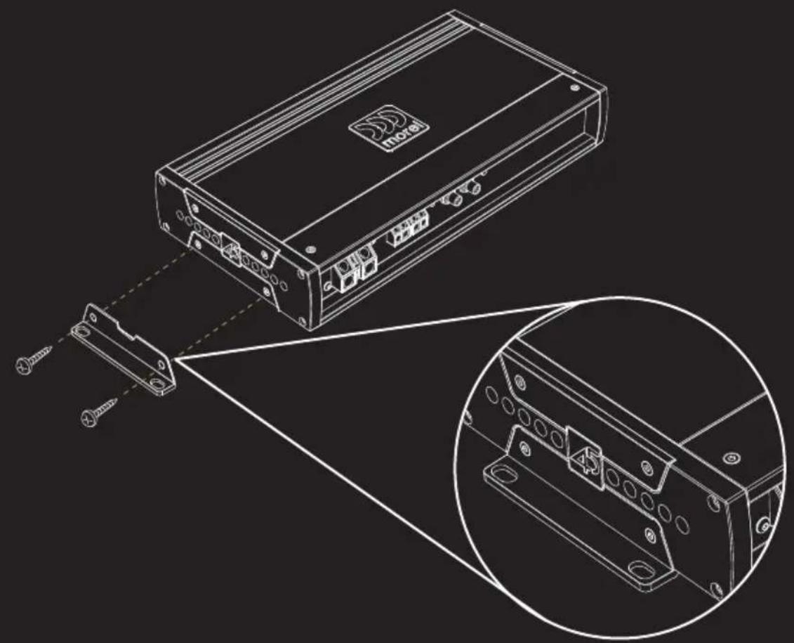
natural_image
Technical line drawing of a device with an external connector and close-up inset showing internal components (no text or symbols)Mounting
Plate location for discreet mount
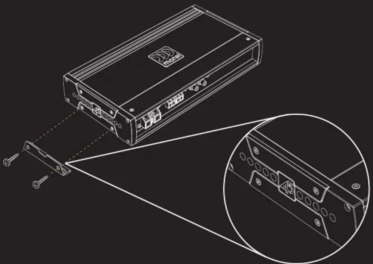
natural_image
Technical line drawing of a device with screwdriver and internal components, showing close-up detail (no text or symbols)Plate location for parcel shelf mounting
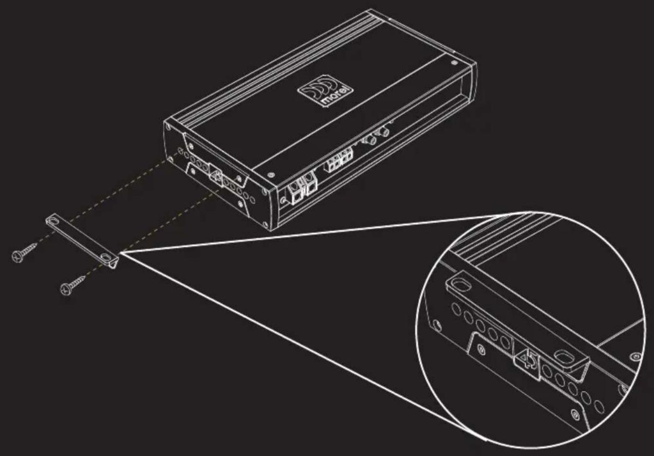
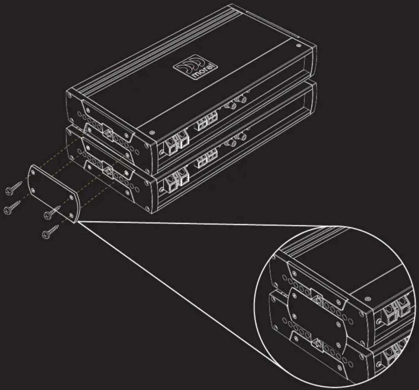
natural_image
Technical line drawing of a device with an external connector and internal components, showing wiring connections (no text or symbols)The MPS Limited chassis also allow for amplifiers to be stacked using the optional MPS-STKP stacking plates (see illustration). When using the stacking plates, it is recommended the base amplifier be securely mounted with a nut and bolt to a non-movable portion of the vehicle. Morel also recommends no more than two amplifiers to be stacked for safety.
natural_image
Technical line drawing of a multi-chamber electronic device with screw spout and connector ports, showing internal wiring connections (no text or symbols)Protection
Protection
Please note that there are no chassis mounted fuses on the MPS Limited amplifiers. Instead these amplifiers use a sophisticated microprocessor controlled protection circuit which enables the amplifier to optimize the current flow coming into the power supply. This design reduces loss within the circuitry, increases efficiency and improves sound dynamics of the amplifier for the best listening experience. However, for the safety of you and your vehicle, please follow instructions for installing an inline fuse (not included) with your MPS Limited amplifier.
Planning and Installation
For best results, determine the best configuration of your new amplifier and plan the wiring routes to ease installation and optimize performance.
- IMPORTANT! Disconnect the vehicle's primary ground terminal from the battery post prior to commencing the installation.
- Make sure the mounting location you chose for the amplifier does not interfere with any functions of the vehicle mechanics and/or electronic devices. Also, be aware of the locations of the gas tank, wiring harnesses, fuel and brake lines, and other vital components of the vehicle prior to drilling any holes in the vehicle's chassis.
- Select high quality signal cables and proper wire. It is highly recommended to use 100% OFC (oxygen free copper) power and speaker wire of proper size for best performance and longevity of the product.
- Do not run power or audio cables on the exterior of the vehicle as this can result in severe damage to the vehicle and person.
- Avoid running power and audio cables next to sensitive electronics within the vehicle, and avoid crossing the signal cables with the power cables.
- Always use rubber grommets when running wire through metal walls or barriers. Use loom to protect the cable from sharp edges or areas of high heat.
- Power amplifiers place an increased load on the electrical charging system. A modern vehicle's factory electrical system should be able to standup to the extra load of an MPS Limited amplifier without concern. However, multiple amplifier systems can draw excess current and create a strain on the electrical system. It is best to consult your audio specialist for advise on whether or not it is necessary to upgrade your electrical system to meet the demands of the audio system.
- Place an insulated in-line fuse holder (not included) of the appropriate current capacity (see specifications) within 16 inches (40cm) of the battery positive (+) terminal. This is to be connected to the (+) power cable connecting the amplifier. Only install the fuse once the power cable has been secured to the amplifier.
- Locate a solid metal area close to the amplifier to connect the ground wire terminal. Use the same gauge wire for ground as for the power wire. The length of the ground wire should not exceed 36 inches (90cm) from the amplifier. To ensure a solid connection, remove surface paint at the ground point prior to securing the connector in place.
MPS 2.150 LIMITED - Features
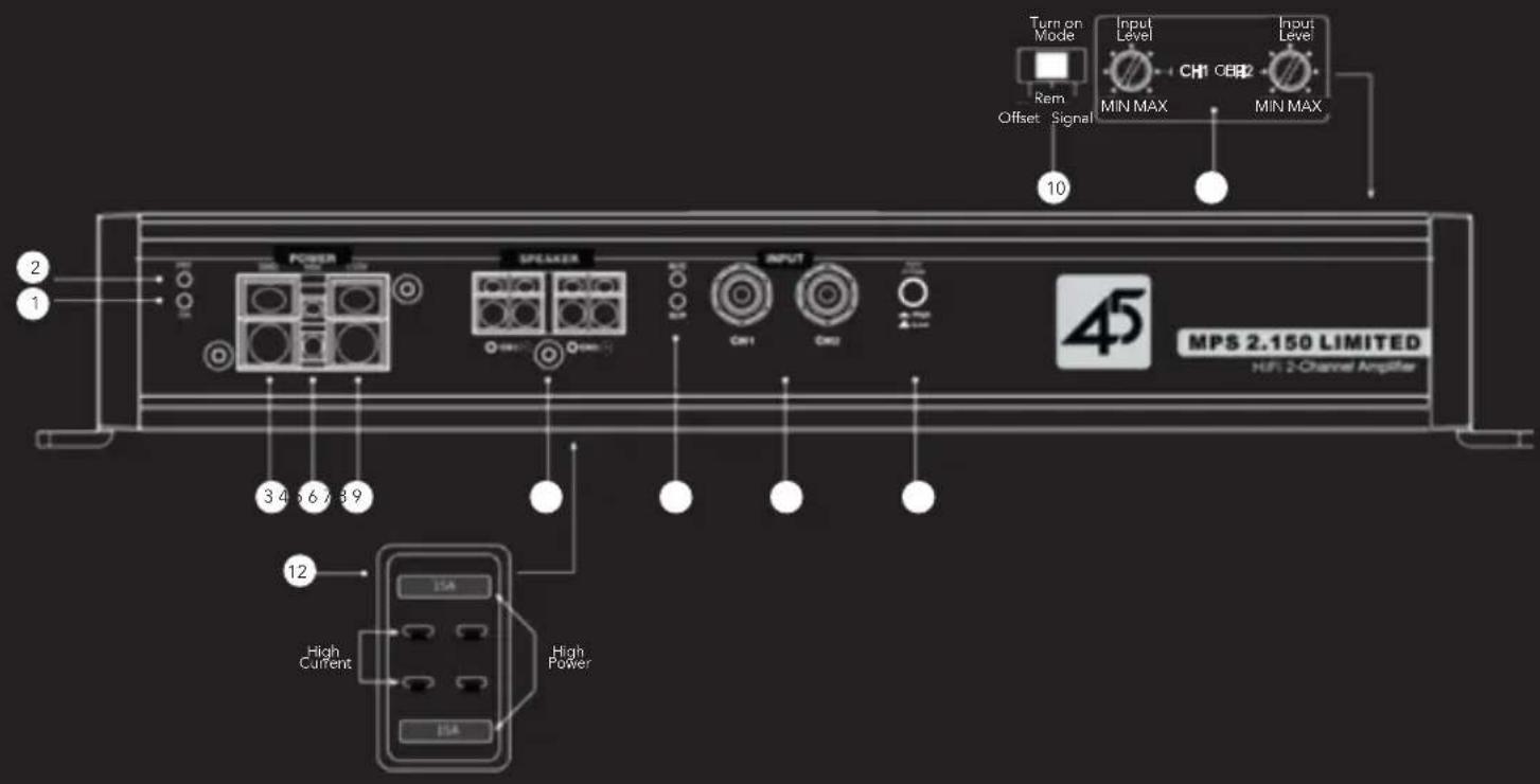
1 Power Status Indicator
The ON LED will illuminate blue when amplifier is properly powered on.
2 Protection Status Indicator
The PRT LED will illuminate red if the amplifier faults and goes into protect mode. There are several reasons that could cause that amplifier fault including over current, over or under voltage, short circuit,
thermal protection, or an internal error within the amplifier. If the fault is caused by thermal protection, the amplifier will reset automatically once the heatsink has cooled to about 70^ C ( 160^ F). If the PRT LED stays illuminated, the power status LED will flash a code indicating the potential issue. See Fault Code at rear of manual.
3 Negative Chassis Ground Connection
Connect an 8 gauge or larger OFC (oxygen-free copper) wire for ground (same gauge used for +12V power wire). The length of the ground wire should not exceed 36 inches (90cm) from the amplifier. To ensure a solid connection, remove surface paint at the ground point prior to securing the connector in place.
4 Remote Turn-On Connector
Connect to wire lead from a switched +12V source. This could be a remote turn on lead from a head unit or switched ignition lead. If neither of these sources is available, switch Turn On Mode to signal sensing or DC offset (see #10)
MPS 2.150 LIMITED - Features
5 +12VDC Power Connection
For optimum performance, connect an 8 gauge or larger OFC (oxygen-free copper) wire to the +12V terminal. This wire should be connected directly to the positive terminal (+12V) of the car's battery in conjunction with a 30 amp inline fuse. For safety purposes, the fuse must be located within 16 inches (40cm) of the battery.
6 Channel 1 & 2 Speaker Outputs
Connect speaker wire up to 10 gauge. Channel 1 and 2 connections can be configured in stereo using the + and - of both channel outputs, or in a bridged configuration using CH1 + and CH2 -.
7 High Power/High Current Mode Indicator
This amplifier has a High Power and High Current power mode. Two LEDs are used to indicate what mode the amplifier is in (refer to #12 for Mode Selection). When High Power mode (default) is selected, the LED marked H/P will illuminate BLUE. When High Current mode is selected, the LED marked H/C will illuminate YELLOW.
8 RCA Inputs
Accepts both low-level and high-level signal via RCA style connectors. Use the Input Voltage Selector (refer to #9) to choose appropriate voltage level.
9 High/Low Level Input Voltage Selector
Select signal input voltage based on the signal source used. When using an aftermarket radio, DSP or line level convertor, select Low for levels up to 4V. When using high-level input from an amplified factory audio system, select High for levels up to 8V. High-level inputs require the MPS-LC line level adaptor (sold separately) to convert amplified speaker outputs from factory audio systems to RCA style connections.
10 Turn-on Mode Selector
Select between 3 modes to turn on the amplifier. When using a switched lead such as the +12v remote output of a radio, use the default position REM. When connecting to a factory audio system or alternative source, select Signal and the amplifier will turn on when it senses voltage through the inputs. DC (DC offset) may be used in some vehicles where signal sensing does not reliably turn the amplifier on.
MPS 2.150 LIMITED - Features
11 Input Level
This amplifier has two input level (gain) adjustments - one for Channel 1 and one for Channel 2. These are used to properly match input levels with the source signal to optimize the amplifier outputs. THEY ARE NOT A VOLUME CONTROL! To set properly, the maximum unclipped output from the radio or source must be known using proper test equipment. The input level adjustments can then be properly set to maximize output without overdriving the amplifier. If the gain is not set properly the amplifier may clip and damage your speakers and the amplifier itself. It is highly recommended to use an audio specialist to properly adjust.
12 High Power/High Current Mode Selector
This amplifier is designed to maximize power in 4-ohm or 2-ohm operation through two repositionable fuses accessible through a removeable window on the bottom of the amplifier.
High Power:
In this default setting, the amplifier will maximize its output when powering 4-ohm speakers in stereo. This requires the fuses to be placed into the outer two receptacles.
High Current:
In the High Current setting, the amplifier will maximize its output when powering a 2-ohm speaker load in stereo or a 4-ohm speaker load when bridged. This requires the fuses to be moved to the inner two receptacles.
MPS 2.150 LIMITED
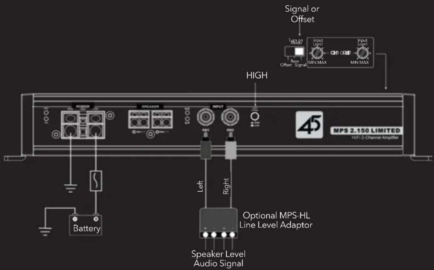
Power and Signal Connections
LOW LEVEL - RCA INPUTS
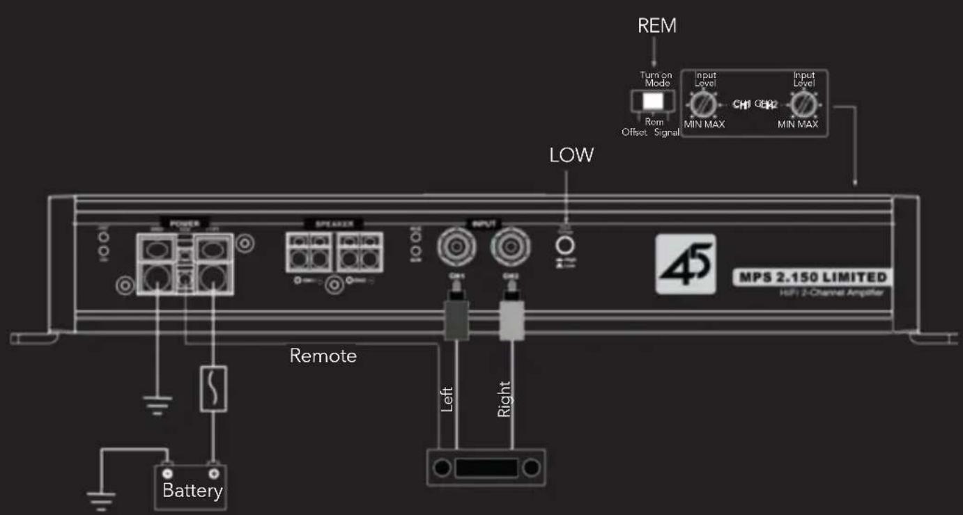
HIGH LEVEL - SPEAKER TO RCA INPUTS
MPS 2.150 LIMITED Speaker Connections
2-CHANNEL STEREO-HIGH POWER (4Ω) MODE
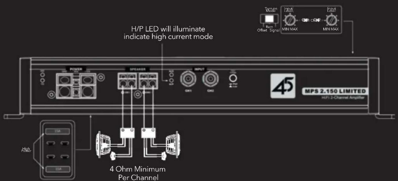
Default setting. Fuses must be positioned to outer fuse holders to maximize output power when connecting a 4-ohm speaker load.
2-CHANNEL STEREO-HIGH CURRENT (2Ω) MODE
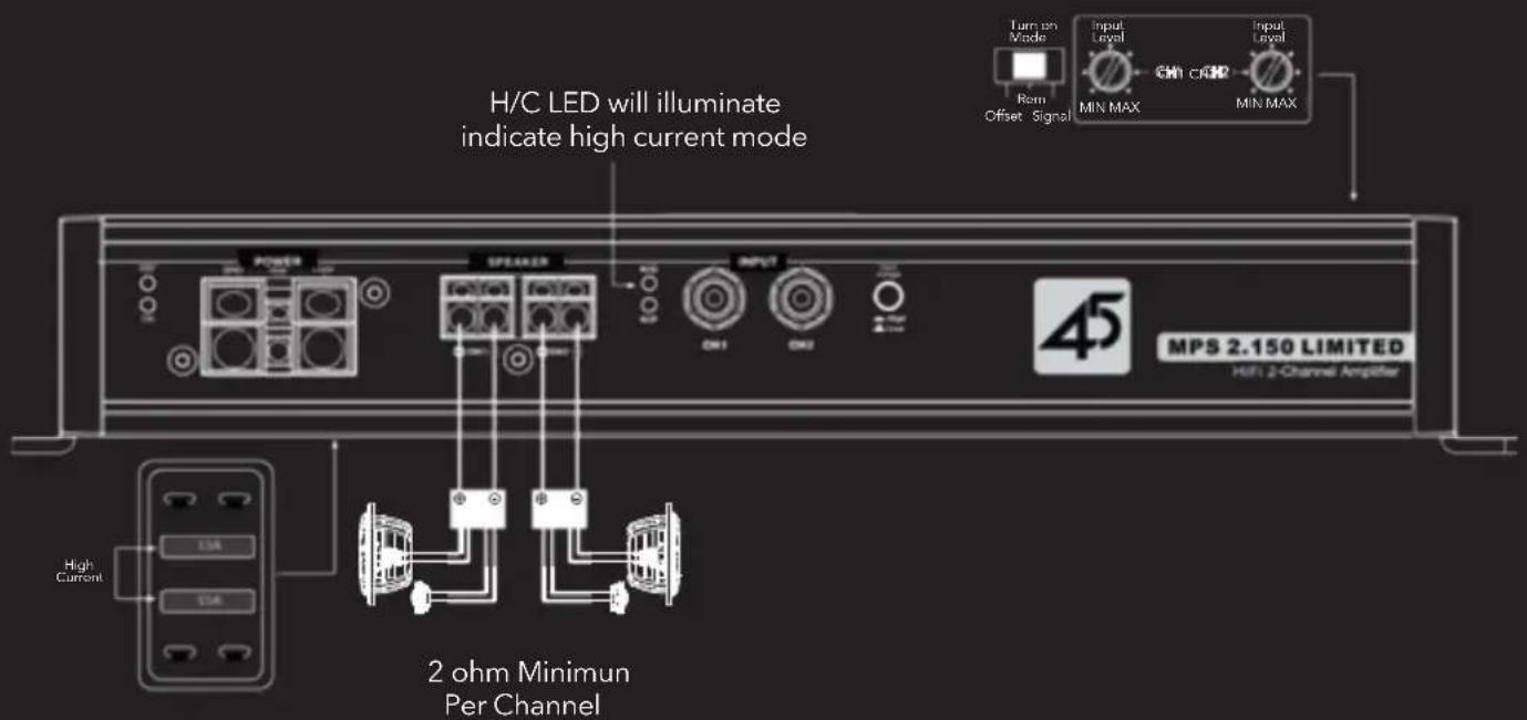
Fuses must be positioned to inner fuse holders to maximize output power when connecting a 2-ohm speaker load
MPS 2.150 LIMITED Speaker Connections
BRIDGED MODE (4Ω MONO LOAD ONLY)
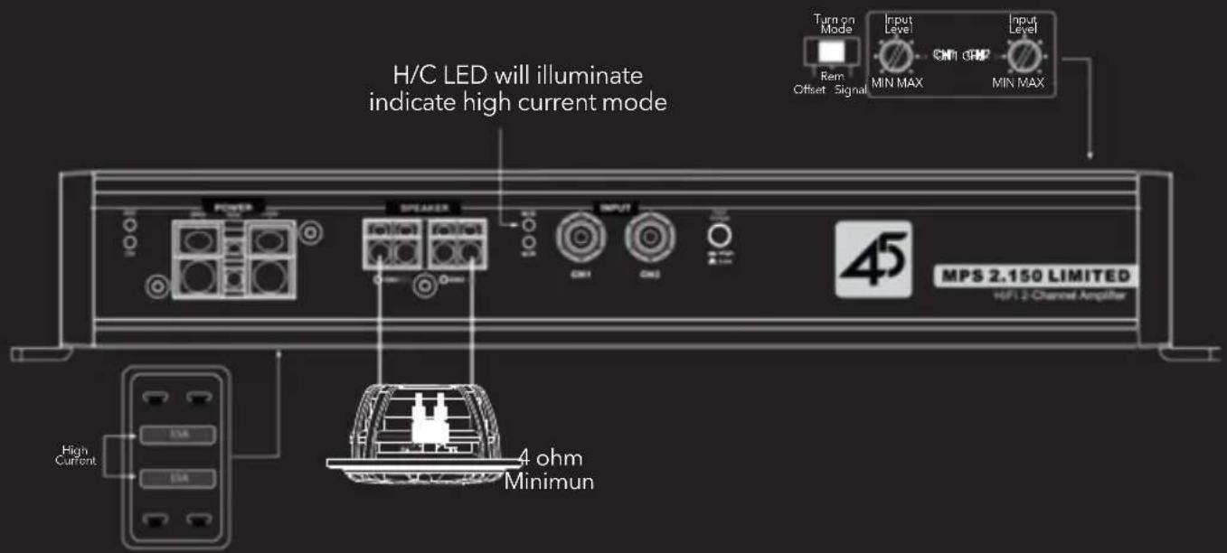
Fuses must be positioned to inner fuse holders labeled "High Current" to maximize output power when connecting a 4-ohm mono speaker load
MPS 1.1100 LIMITED - Features
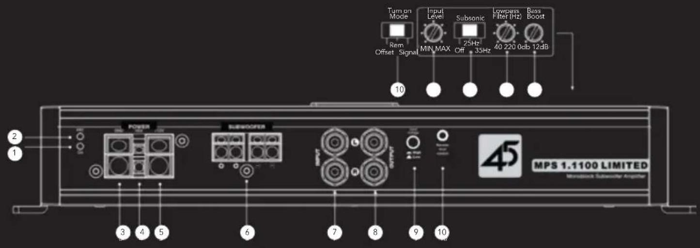
1 Power Status Indicator
The ON LED will illuminate blue when amplifier is properly powered on.
2 Protection Status Indicator
The PRT LED will illuminate red if the amplifier faults and goes into protect mode. There are several reasons that could cause that amplifier fault including over current, over or under voltage, short circuit, thermal protection, or an internal error within the amplifier. If the fault is caused by thermal protection, the amplifier will reset automatically once the heatsink has cooled to about 70°C (160°F). If the PRT LED stays illuminated, the power status LED will flash a code indicating the potential issue. See Fault Code at rear of manual.
3 Negative Chassis Ground Connection
Connect an 8 gauge or larger OFC (oxygen-free copper) wire for ground (same gauge used for +12V power wire). The length of the ground wire should not exceed 36 inches (90cm) from the amplifier. To ensure a solid connection, remove surface paint at the ground point prior to securing the connector in place.
4 Remote Turn-On Connector
Connect to wire lead from a switched +12V source. This could be a remote turn on lead from a head unit or switched ignition lead. If neither of these sources is available, switch Turn On Mode to signal sensing or DC offset (see #10).
MPS 1.1100 LIMITED - Features
5 +12VDC Power Connection
For optimum performance, connect a 4 gauge OFC (oxygen-free copper) wire to the +12V terminal. This wire should be connected directly to the positive terminal (+12V) of the car's battery in conjunction with a 100 amp inline fuse. For safety purposes, the fuse must be located within 16 inches (40cm) of the battery.
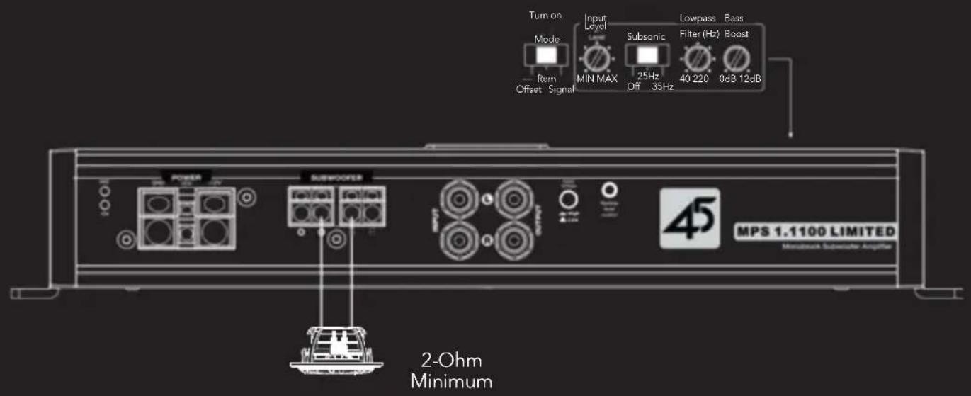
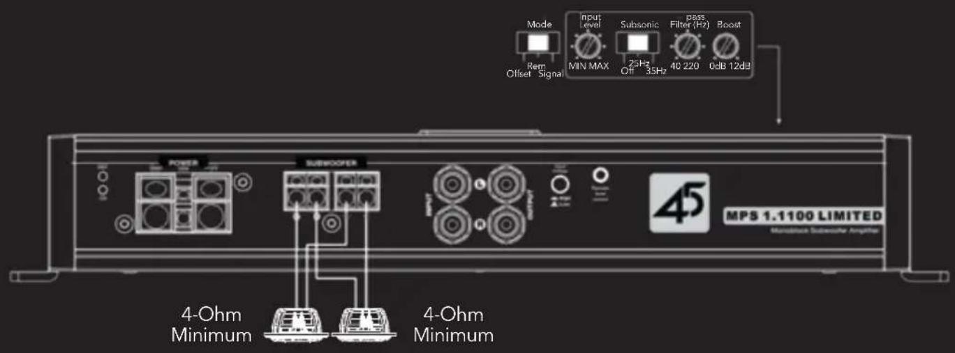
6 Subwoofer Outputs
There are two speaker terminals labeled + and two terminals labeled -. This is a single channel amplifier so both pairs of the terminals are internally parallel. See Speaker Connections.
7 RCA Inputs
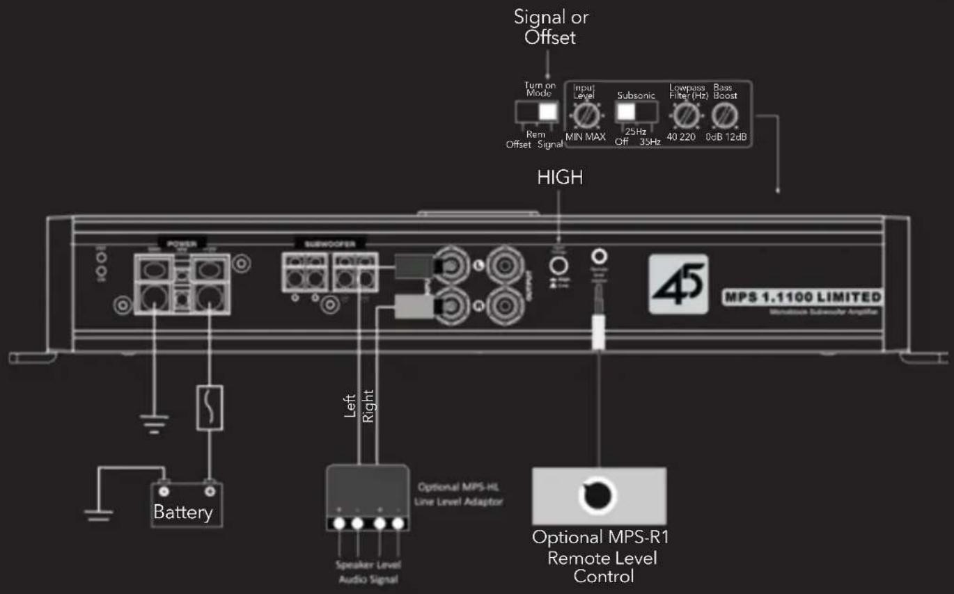
Accepts both low-level and high-level signal via RCA style connectors. Use Input Voltage Selector to choose appropriate voltage level. High-level inputs require the MPS-LC line level adaptor (sold separately) to convert amplified speaker outputs from factory audio systems to RCA style connections.
8 RCA Outputs
These are non-buffered through-pass outputs used to connect additional amplifiers. Not that the internal crossover does not affect signal to these outputs.
9 High/Low Level Input Voltage Selector
Select signal input voltage based on the type of input used. When using an aftermarket radio, DSP or line level convertor, select Low for levels up to 4V. When using high-level input from an amplified factory audio system, select High for levels up to 20V.
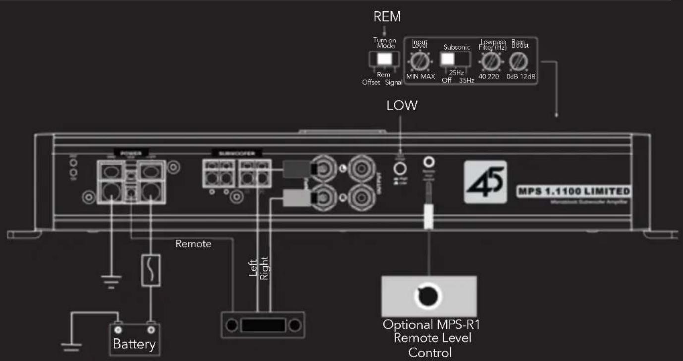
10 Remote Level Control
Connection for optional MPS-R1 remote subwoofer level control. This allows the user to adjust the output level of the amplifier on the fly from a remote location within the vehicle.
11 Turn On Mode Selector
Select between 3 modes to turn on the amplifier. When using a switched lead such as the remove output of a radio, select the default position REM. When connecting to a factory audio system or alternative source, select Signal and the amplifier will turn on when it senses voltage through the inputs. DC (DC offset) may be used in some vehicles where signal sensing does not reliably turn the amplifier on.
MPS 1.1100 LIMITED - Features
12 Input Sensitivity Controller
These are used to properly match input levels with the source signal to optimize the amplifier outputs. THEY ARE NOT A VOLUME CONTROL! To set properly, the maximum unclipped output from the radio or source must be known using proper test equipment. The input level adjustments can then be properly set to maximize output without overdriving the amplifier. If the gain is not set properly the amplifier may clip and damage your speakers and the amplifier itself. It is highly recommended to use an audio specialist to properly adjust.
13 Subsonic Filter Selector
Designed to be used with small subwoofers or vented enclosures with a high tuning frequency, users can opt to select a 12dB subsonic filter (highpass crossover) centered at either 25Hz or 35Hz.
14 Lowpass Frequency Controller
This amplifier is designed as strictly a subwoofer amplifier and therefore the crossover cannot be defeated. The crossover frequency controller allows the user to adjust the frequency of the Lowpass crossover filter between 40 and 220Hz.
15 Bass Boost Controller
This allows the user to boost the output of the amplifier centered around 45Hz with a range of 0 to +12dB.
MPS 1.1100 LIMITED
Power and Signal Connections
LOW LEVEL - RCA INPUTS
HIGH LEVEL - SPEAKER TO RCA INPUTS
MPS 1.1100 LIMITED Speaker Connections
SINGLE SUBWOOFER CONNECTION
DUAL SUBWOOFER CONNECTION
Fault Code Indicator
| UNDERVOLTAGE | Power supply voltage is too low for normal operation. Outputs mute. | Blue LED: light outRed LED: 2 flashes |
| OVERVOLTAGE | Power supply voltage is too high for normal operation. Outputs mute. | Blue LED: light outRed LED: 3 flashes |
| OVER HEAT (Heatsink) | Amplifier heatsink temperature in excess of 80-degrees Celcius. Outputs mute until temperature decreases to normal range. | Blue LED: onRed LED: 1 flashes |
| OVER HEAT (Power Supply) | Amplifier power supply has over heated. Outputs mute until temperature decreases to normal range. | Blue LED: onRed LED: 2 flashes |
| OVER CURRENT | Excessive current draw at power supply. Speaker load may be of too low an impedance or amplifier may be overdriven. Outputs mute. | Blue LED: light outRed LED: 1 flash |
| INTERNAL POWER FAILURE | Amplifier heatsink temperature in excess of 80-degrees Celcius. Outputs mute until temperature decreases to normal range. | Blue LED: onRed LED: 1 flashes |
Morel warrants this product to be free of defects in materials and workmanship for a period of four (4) years from the original date of purchase if purchased and installed by an authorized Morel retailer, and one (1) year if purchased over counter or online. This warranty is not transferable and applies only to the original purchaser from an authorized retailer in the USA only. Should service be necessary under this warranty for any reason due to manufacturing defect or malfunction, Morel will (at its discretion) repair or replace the defective product with new or remanufactured product at no charge. Damaged cause by the following is not covered under warranty: accident, misuse, abuse, product modification or neglect, failure to follow installation instructions, unauthorized repairs, or misrepresentations by the seller. This warranty does not cover incidental or consequential damages and does not cover costs associated with removing or reinstalling the amplifier. Cosmetic damage due to accident or normal wear and tear is not covered under warranty.
International
Products purchased outside the USA are covered only by that country's Authorized Morel reseller and not Morel. Consumers needing service or warranty information for these Morel products must contact that country's reseller or distributor for warranty information including duration and coverage.
Specifications
MPS 1.1100 LIMITED MPS 2.150 LIMITEDMODEL
| HIGH POWER | HIGH CURRENT | ||
| 4Ω stereo N/A | 150w x 2 | 100w x 2 | |
| 2Ω stereo | N/A | N/A | 150w x 2 |
| 4Ω Mono/Bridged | 650w | N/A | 300w x 1 |
| 2Ω Mono/Bridged | 1,100w | N/A | N/A |
| Minimum Impedance 2 Ohm | 4 Ohm Stereo 2 Ohm Stereo | ||
SPECIFICATIONS
| THD+N 0.10% | 0.02% | |
| Frequency Response (+/-1dB) | 10Hz~220Hz | 10Hz~80kHz |
| S/N Ratio (Rated Power, A-weighted) | 102dB | 111dB |
| S/N Ratio @ 1W (CEA-2006) | 75dB | 91dB |
| Channel Separation | NA | 68dB |
| Operating Voltage | 8.1-16.5 VDC | 8.1-16.5 VDC |
| Input Sensitivity | Low: 0.2-4V | Low: 0.2-4V |
| High: 0.8-20V | High: 0.4-8V | |
PREAMP
| Filter Slope (dB/Octave) 12dB/oct | N/A | |
| Crossover Filter | Lowpass 40Hz–220Hz | N/A |
| Subsonic Filter | OFF/25Hz/35Hz | N/A |
| Bass boost | 0dB to +12dB | N/A |
| Remote Level Control | Optional MPS-R1 | N/A |
| Pass-Through Preamp Output | YES | N/A |
DIMENSIONS
| Height (H) 2" (51mm) | 2" (51mm) | |
| Width (W) | 6.7" (170mm) | 6.7" (170mm) |
| Length (L) | 12.65" (322mm) | 12.65" (322mm) |
FUSE RECOMMENDATION
100 Amp 40 Amp
*All specifications are measured using 14.4VDC
Morel is constantly developing new technology and processes to improve its products.
Morel reserves the right to modify specifications or change product design without notice.
- PRODUCT REGISTRATION
- Available Accessories
- Practice Safe Sound!
- Precaution
- Mounting
- Protection
- Planning and Installation
- MPS 2.150 LIMITED - Features
- Power Status Indicator
- Protection Status Indicator
- Negative Chassis Ground Connection
- Remote Turn-On Connector
- +12VDC Power Connection
- Channel 1 & 2 Speaker Outputs
- High Power/High Current Mode Indicator
- RCA Inputs
- High/Low Level Input Voltage Selector
- Turn-on Mode Selector
- Input Level
- High Power/High Current Mode Selector
- High Power:
- High Current:
- MPS 2.150 LIMITED
- Power and Signal Connections
- MPS 2.150 LIMITED Speaker Connections
- MPS 1.1100 LIMITED - Features
- Subwoofer Outputs
- RCA Inputs
- RCA Outputs
- Remote Level Control
- Turn On Mode Selector
- Input Sensitivity Controller
- Subsonic Filter Selector
- Lowpass Frequency Controller
- Bass Boost Controller
- MPS 1.1100 LIMITED
- MPS 1.1100 LIMITED Speaker Connections
- International
- Specifications
- FUSE RECOMMENDATION
Brand : Morel
Model : MPS 1.1100 Limited
Category : Receiver