MPS 1.550 - Receiver Morel - Free user manual and instructions
Find the device manual for free MPS 1.550 Morel in PDF.


| Product Type | Mono subwoofer amplifier |
| RMS Power @ 4 Ohm | 350W x 1 |
| RMS Power @ 2 Ohm | 550W x 1 |
| Frequency Response | 10 - 220 Hz |
| Signal-to-Noise Ratio | 100 dB (A-weighted) |
| Input Voltage Range (Low) | 200 mV - 5 V |
| Input Voltage Range (High) | 800 mV - 20 V |
| Crossover Type | Low-pass, 12 dB/octave |
| Crossover Frequency Range | 40 - 220 Hz |
| Subsonic Filter | Selectable Off / 25 Hz / 35 Hz |
| Bass Boost | 0 - 12 dB @ 45 Hz |
| Remote Level Control | Optional MPS-R1 (sold separately) |
| Turn-On Modes | Remote (REM), Signal Sensing, DC Offset |
| Protection Features | Over current, short circuit, thermal protection |
| Power Supply | 12 V DC, negative ground |
| Recommended Fuse | 50 A inline (within 16" of battery) |
| Dimensions (H x W x D) | 2" x 6.7" x 8.44" (51 x 170 x 214.5 mm) |
| Cooling | Heatsink with fins; require 2" (50 mm) clearance |
| Package Contents | Amplifier, hex wrenches (2, 2.5, 3 mm), mounting screws, user manual, top panel screws |
Frequently Asked Questions - MPS 1.550 Morel
User questions about MPS 1.550 Morel
0 question about this device. Answer the ones you know or ask your own.
Ask a new question about this device
Download the instructions for your Receiver in PDF format for free! Find your manual MPS 1.550 - Morel and take your electronic device back in hand. On this page are published all the documents necessary for the use of your device. MPS 1.550 by Morel.
USER MANUAL MPS 1.550 Morel
We thank you for choosing Morel amplifiers to complement your car audio system. The new MPS amplifiers were developed with the same passion and innovative philosophy that is driving all of Morel's product development. The MPS amplifiers are musical, dynamic, with clean, uncolored power that can drive speakers to their full sonic potential.
It is very important to carefully read this manual to ensure safe and optimal operation of the amplifier. We highly recommend to have a professional installer integrate the amp into the sound system. There are many parameters that needs to be taken into consideration when installing an amplifier to safeguard that the car's electrical system is not compromised in any way and the sound system is tuned properly.
SERIAL NUMBER
Please take the time to enter the serial number in the space provided below. The serial number can be found on the bottom panel of the amplifier and on the amplifier packaging. This is required in the event that your amplifier requires warranty service and may be helpful in recovering your amplifier in case of a theft. Be sure to store you this manual in a safe location.
Serial Number:

All Morel MPS amplifiers comply with CE and EMC regulations.

MOREL PERFORMANCE SERIES AMPLIFIERS / Owner's ManualMOREL3 PERFORM
PACKAGE CONTENT
• (1) MPS amplifier
• (1) 2mm hex wrench
• (1) 2.5mm hex wrench
• (1) 3mm hex wrench
• (4) Mounting screws
• (1) User manual
• (2) Top panel replacement screws
AVAILABLE ACCESSORIES
- MPS-R1 subwoofer remote level control (works with MPS 1.550 and MPS 5.950 only)
• MPS-HL high-low level adaptor with 50-ohm load resistor

PRACTICE SAFE SOUND!
Studies have shown that continuous exposure to high sound pressure levels from high power audio systems can lead to permanent hearing loss. Additionally, high volume levels can obscure noises from outside your vehicle such as emergency vehicles and horns. As a valued Morel customer, we urge you to use common sense and practice restraint in the operation of this product.

PRECAUTION
The MPS amplifiers are designed to work with a 12V DC electrical system with negative to ground. Use of this product in vehicles with positive ground and/or voltages other than 12V may result in damage to the product and/or vehicle and will void the warranty.

PLEASE MAKE SURE TO CAREFULLY READ AND UNDERSTAND ALL INSTRUCTIONS PRIOR TO INSTALLATION
MOUNTING THE AMPLIFIER
Choose a location for the amplifier with ample ventilation for optimum cooling performance. Be sure the amplifier is mounted with at least 2-inches (50mm) of clearance around the chassis, and never fully enclosure the amplifier in a confined space without active ventilation. It is strongly discouraged to mount the amplifier upside down as this will limit the heatsink's ability to remove heat from the circuitry. Also avoid mounting in areas of direct sunlight and in areas of high vibration, such as a subwoofer enclosure.
Proper mounting consists of the chassis being mounted with the base of the amplifier parallel with the floor or perpendicular to the floor with the fins of the heatsink facing upward for effective cooling.
Your amplifier should always be installed in a location that will remain free of moisture and dirt, and in a manner that does not interfere with any of the electronics or safety gear of the vehicle.
For safety purposes, be sure to take the time to properly mount the amplifier using suitable mounting hardware so the amplifier does not come loose in the event of a collision or unforeseen circumstance.
PROTECTION
Please note that there are no chassis mounted fuses on the MPS amplifiers. Instead our design uses a microprocessor controlled protection circuit which enables the amplifier to optimize the current flow coming into the power supply. This design lowers loss within the circuitry, increase the power output and improves the sound dynamics of the amplifier for the best listening experience. However, for the safety of you and your vehicle, please follow instructions for installing an inline fuse with your amplifier.
PLANNING AND INSTALLATION
For best results, determine the best configuration of your new amplifier and plan the wiring routes to ease installation and optimize performance.
- IMPORTANT! Disconnect the vehicle's primary ground terminal from the battery post prior to commencing the installation.
- Make sure the mounting location you chose for the amplifier does not interfere with any functions of the vehicle mechanics and/or electronic devices. Also, be aware of the locations of the gas tank, wiring harnesses, fuel and brake lines, and other vital components of the vehicle prior to drilling any holes in the vehicle's chassis.
- Select high quality signal cables and proper wire. It is highly recommended to use 100% OFC (oxygen free copper) power and speaker wire of proper size for best performance and longevity of the product.
- Do not run power or audio cables on the exterior of the vehicle, including underneath, as this can result in severe damage to the vehicle and person.
- Avoid running power and audio cables next to sensitive electronics within the vehicle, and be sure to route the signal cables away from the power cables.
- Always use rubber grommets when running wire through metal walls or barriers, and use loom to protect the cable from sharp edges or areas of high heat.
- Power amplifiers place an increased load on the electrical charging system. Generally, factory charge systems in good condition should be able to withstand the extra load of an MPS amplifier without a problem. However, multiple amplifier systems can draw excess current and create a serious strain on the electrical system. It is best to consult your audio specialist for advise on whether or not it is necessary to upgrade your electrical system to meet the demands of the audio system.
- Place an insulated in-line fuse holder of the appropriate current capacity within 16 inches (40cm) of the battery positive (+) terminal. Connect to this to the power cable connecting the positive terminal of the amplifier. This fuse is designed to protect the vehicle in the event of a short. Only install the fuse once the power cable has been secured to the amplifier.
- Locate a solid metal area as close to the amplifier as possible to connect the ground wire terminal. Use the same gauge wire for ground as for the power wire. The length of the ground wire should not exceed 36 inches (90cm) from the amplifier. To ensure a solid connection, remove surface paint at the ground point prior to securing the connector in place.
MPS 4.400 / Features
1. Power Status Indicator
LED illuminates blue when amplifier is properly powered on
2. Protection Status Indicator
LED will illuminate red when the amplifier is in faults into protect mode related to over current, short circuit, thermal protection or internal error within the amplifier. If the fault is caused by thermal protection, the amplifier will reset automatically once the heatsink has cooled to about 70°C (160°F). If the protection LED stays illuminated, turn the amplifier off and check the speakers and wiring.
3. Negative Chassis Ground Connector
Connect to a matching B gauge or larger OFC (oxygen-free copper) wire for ground as used the power wire. The length of the ground wire should not exceed 36 inches (90cm) from the amplifier. To ensure a solid connection, remove surface paint at the ground point prior to securing the connector in place.
4. Remote Turn-On Connector
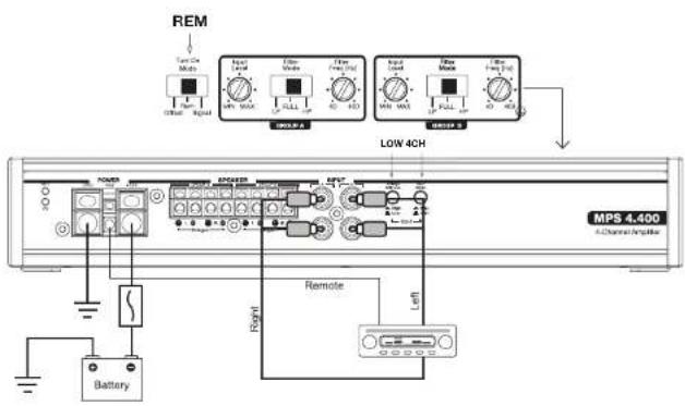
Connect to wire lead from a switched +12V source. This could be from a head unit or switched ignition lead. If neither of these sources is available, switch Turn On Mode to signal sensing or DC offset.
5. +12VDC Power Connection
For safety and optimum performance, connect an 8 gauge or larger OFC (oxygen-free copper) wire to the +12V terminal. Connect directly to the positive terminal (+12V) of the car's battery via a 50A inline fuse. The fuse must be located within 16 inches (40cm) of the battery.
6-7. Left & Right Speaker Outputs
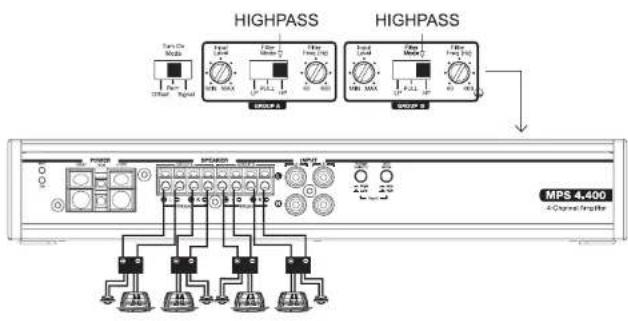
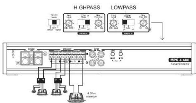
Connect speaker wire up to 10 gauge. Group A and Group B connections can be configured in stereo using the + and - of both L & R outputs, or in a mono configuration using the L+ and R- within Group A or Group B (DO NOT cross-wire between Group A and B). 3-Channel can also be configured using a stereo in Group A and mono in Group B.
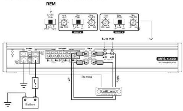
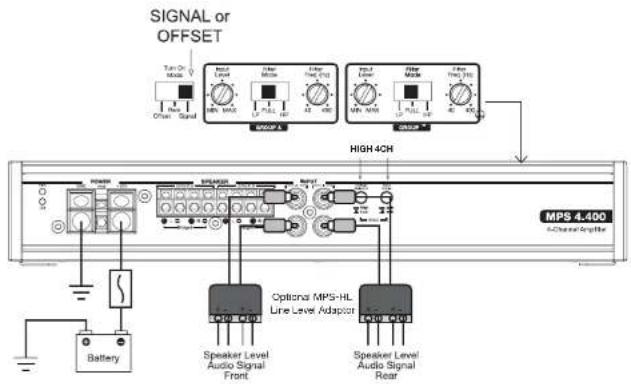
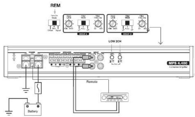
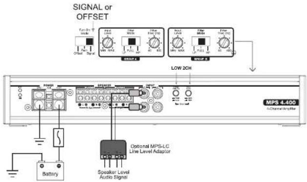
8-9. RCA Inputs
Accepts both low-level and high-level signal via RCA style connectors. Use Input Voltage Selector to choose appropriate voltage level, and 2/4 channel input selector for number of inputs used. High-level inputs require the MPS-HL line level adaptor (sold separately) to convert amplified speaker outputs from factory audio systems to RCA style connections.
10. High/Low Level Input Voltage Selector
Select signal input voltage based on the type of input used. When using an aftermarket radio, DSP or line level converter, select Low for levels up to 5V. When using high-level input from an amplified factory audio system, select High for levels up to 10V.
11. 2/4 Channel Input Mode Selector
Selector allows amplifier to accept signal from 2 or 4 channels of input. Selecting 2CH will take signal from Group A L and R input only and send signal to Group B L and R channels.

12. Turn On Mode Selector
Select between 3 modes to turn on the amplifier. When using a switched lead such as the remove output of a radio, select the default position REM. When connecting to a factory audio system or alternative source, select Signal and the amplifier will turn on when it senses voltage through the inputs. DC (DC offset) may be used in some vehicles where signal sensing does not reliably turn the amplifier on.

8
13 & 16. Input Sensitivity Controller
The input sensitivity controller (gain) is used to properly match input signal levels from the signal source to optimize the amplifier outputs. THIS IS NOT A VOLUME CONTROL! To properly set, the maximum unclipped output from the radio or source must be known using either an oscilloscope or, at minimum, a multi-meter and test program. The amplifier can then be properly set to maximize output. If the gain is not set properly the amplifier may clip early and damage your speakers and the amplifier itself. It is highly recommended to use an audio specialist to properly adjust. Independent gain controls are available for Group A and Group B channels.
14 & 17. Crossover Filter Selector
Select between Full (full range), LP (lowpass) and HP (highpass) depending on the requirements of the speakers in your system. Selecting LP or HP turns on a 12dB filter that can be adjusted using the Filter Frequency. This is selected independently for Group A and Group B channels.
15 & 18. Crossover Frequency Controller
Use this feature to adjust the frequency of the crossover filter between 40 and 400Hz. This is controlled independently for Group A and Group B channels.
MPS 4.400 / Power And Signal Connections
4-CHANNEL LOW LEVEL - RCA INPUTS

MOREL PERFORMANCE SERIES AMPLIFIERS / Owner's ManualMORELPERFORM
4-CHANNEL HIGH LEVEL - SPEAKER TO RCA INPUTS
2-CHANNEL LOW LEVEL - RCA INPUTS

10
2-CHANNEL HIGH LEVEL - SPEAKER TO RCA INPUTS
2-CHANNEL BRIDGED OUTPUTS - LOW LEVEL RCA INPUTS

MOREL PERFORMANCE SERIES AMPLIFIERS / Owner's ManualMOREL PERFORM
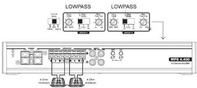
MPS 4.400 / Speaker Connections
4-CHANNEL STEREO MODE - HIGHPASS
3-CHANNEL STEREO + MONO MODE - HIGHPASS + LOWPASS

12
2-CHANNEL BRIDGED MODE - STEREO HIGHPASS
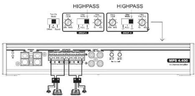
2-CHANNEL BRIDGED MODE - LOWPASS SUBWOOFER

MOREL PERFORMANCE SERIES AMPLIFIERS / Owner's ManualMOREL3PERFORM
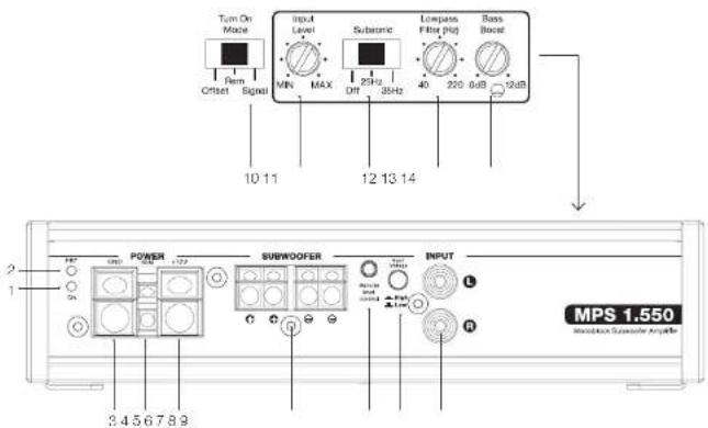
MPS 1.550 / Features
1. Power Status Indicator
LED illuminates blue when amplifier is properly powered on
2. Protection Status Indicator
LED will illuminate red when the amplifier is in faults into protect mode related to over current, short circuit, thermal protection or internal error within the amplifier. If the fault is caused by thermal protection, the amplifier will reset automatically once the heatsink has cooled to about 70°C (160°F). If the protection LED stays illuminated, turn the amplifier off and check the speakers and wiring.
3. Negative Chassis Ground Connector
Connect to a matching 8 gauge or larger OFC (oxygen-free copper) wire for ground as used the power wire. The length of the ground wire should not exceed 36 inches (90cm) from the amplifier. To ensure a solid connection, remove surface paint at the ground point prior to securing the connector in place.
4. Remote Turn-On Connector
Connect to wire lead from a switched +12V source. This could be from a head unit or switched ignition lead. If neither of these sources is available, switch Turn On Mode to signal sensing or DC offset.
5. +12VDC Power Connection
For safety and optimum performance, connect an 8 gauge or larger OFC (oxygen-free copper) wire to the +12V terminal. Connect directly to the positive terminal (+12V) of the car's battery via a 50A inline fuse. The fuse must be located within 16 inches (40cm) of the battery.
6. Subwoofer Outputs
There are two speaker connections are labeled + and -. The two output connections are internally parallel as this is a single channel amplifier. When using both sets of + and -, you will need to use Ohm's law to calculate the impedance in a parallel configuration. Connect speaker wire up to 10 gauge.
7. Remote Level Control
Connector for optional MPS-R1 remote subwoofer level control. This allows the user to adjust the output level of the amplifier on the fly from a remote location within the vehicle.

14
8. High/Low Level Input Voltage Selector
Select signal input voltage based on the type of input used. When using an aftermarket radio, DSP or line level converter, select Low for levels up to 5V. When using high-level input from an amplified factory audio system, select High for levels up to 20V.
9. RCA Inputs
Accepts both low-level and high-level signal via RCA style connectors. Use Input Voltage Selector to choose appropriate voltage level. High-level inputs require the MPS-HL line level adaptor (sold separately) to convert amplified speaker outputs from factory audio systems to RCA style connections.

MOREL PERFORMANCE SERIES AMPLIFIERS / Owner's ManualMOREL5PERFORM
10. Turn On Mode Selector
Select between 3 modes to turn on the amplifier. When using a switched lead such as the remove output of a radio, select the default position REM. When connecting to a factory audio system or alternative source, select Signal and the amplifier will turn on when it senses voltage through the inputs. DC (DC offset) may be used in some vehicles where signal sensing does not reliably turn the amplifier on.
11. Input Sensitivity Controller
The input sensitivity controller (gain) is used to properly match input signal levels from the signal source to optimize the amplifier outputs. THIS IS NOT A VOLUME CONTROL! To properly set, the maximum unclipped output from the radio or source must be known using either an oscilloscope or, at minimum, a multi-meter and test program. The amplifier can then be properly set to maximize output. If the gain is not set properly the amplifier may clip early and damage your speakers and the amplifier itself. It is highly recommended to use an audio specialist to properly adjust,
12. Subsonic Filter Selector
Designed to be used with small subwoofers or vented enclosures with a high tuning frequency, users can opt to select a 12dB subsonic filter (highpass crossover) centered at either 25Hz or 35Hz.
13. Lowpass Frequency Controller
This amplifier is designed as strictly a subwoofer amplifier and therefore the crossover cannot be defeated. The crossover frequency controller allows the user to adjust the frequency of the Lowpass crossover filter between 40 and 220Hz.
14. Bass Boost Controller
This allows the user to boost the output of the amplifier centered around 45Hz with a range of 0 to +12dB.

16
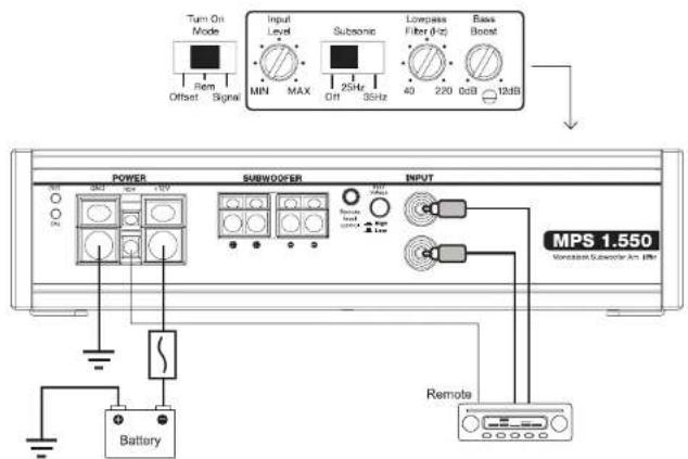
LOW LEVEL RCA INPUTS
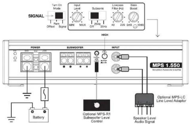
HIGH LEVEL SPEAKER TO RCA INPUTS

MOREL PERFORMANCE SERIES AMPLIFIERS / Owner's ManualMORELYPERFORM
MPS 1.550 / Speaker Connections
SINGLE SUBWOOFER CONNECTION
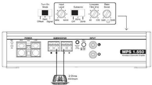
DUAL SUBWOOFER CONNECTION
![Turn On Mode Input Level Subsonic Lowpass Filter [Hz] Bass Boost Offset Signal MIN MAX 25Hz OFF 35Hz 40 220 0dB 12dB POWER SUSWOOFER INPUT MPS 1.550 Vasiblock Subwoofer Analyzer 4 Ohms minimum 4 Ohms minimum](/content/2026/05/877028/images/48869e0ed6c082090104d0ae71523bdf8081df2ec075a8b74d68d31e81ec3182.jpg)
MPS 5.950 / Features
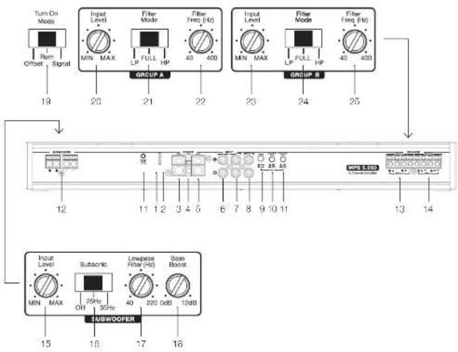
1. Power Status Indicator
LED illuminates blue when amplifier is properly powered on
2. Protection Status Indicator
LED will illuminate red when the amplifier is in faults into protect mode related to over current, short circuit, thermal protection or internal error within the amplifier. If the fault is caused by thermal protection, the amplifier will reset automatically once the heatsink has cooled to about 70°C (160°F). If the protection LED stays illuminated, turn the amplifier off and check the speakers and wiring.
3. Negative Chassis Ground Connector
Connect to a matching 4 gauge OFC or larger OFC (oxygen-free copper) wire for ground as used the power wire. The length of the ground wire should not exceed 36 inches (90cm) from the amplifier. To ensure a solid connection, remove surface paint at the ground point prior to securing the connector in place.
4. Remote Turn-On Connector
Connect to wire lead from a switched +12V source. This could be from a head unit or switched ignition lead. If neither of these sources is available, switch Turn On Mode to signal sensing or DC offset.
5. +12VDC Power Connection
For safety and optimum performance, connect an 4 gauge OFC or larger OFC (oxygen-free copper) wire to the +12V terminal. Connect directly to the positive terminal (+12V) of the car's battery via a 50A inline fuse. The fuse must be located within 16 inches (40cm) of the battery.
6-8. RCA Inputs
Accepts both low-level and high-level signal via RCA style connectors. Separate inputs can be used for Group A, Group B and Subwoofer channels. Use Input Voltage Selector to choose appropriate voltage level, and 2/4 channel and subwoofer mode input selector for number of inputs used. High-level inputs require the MPS-HL line level adaptor (sold separately) to convert amplified speaker outputs from factory audio systems to RCA style connections.
9. High/Low Level Input Voltage Selector
Select signal input voltage based on the type of input used. When using an aftermarket radio, DSP or line level converter, select Low for levels up to 5V. When using high-level input from an amplified factory audio system, select High for levels up to 10V on Group A & B inputs, and up to 20V on subwoofer inputs.
10. 2/4 Channel Input Mode Selector
Selector allows amplifier to accept signal from 2 or 4 channels of input. Selecting 2CH will take signal from Group A L and R input only and send signal to Group B L and R channels.
11. Subwoofer Input Mode Selector
Selector allows amplifier to accept signal from Subwoofer inputs or Group A & B channels of input. Selecting 4CH will take signal from Group A and B only and send signal to Subwoofer channel.
12. Subwoofer Outputs
There are two speaker connections are labeled + and -. The two output connections are internally parallel as this is a single channel amplifier. When using both sets of + and -, you will need to use Ohm's law to calculate the impedance in a parallel configuration. Connect speaker wire up to 10 gauge.Group A Left & Right Speaker Outputs
13-14. Left & Right Speaker Outputs
Connect speaker wire up to 10 gauge. Group A and Group B connections can be configured in stereo using the + and - of both L & R outputs, or in a mono configuration using the L+ and R- within Group A or Group B (DO NOT cross-wire between Group A and B).
15. Input Sensitivity Controller
The input sensitivity controller (gain) is used to properly match input signal levels from the signal source to optimize the amplifier outputs. THIS IS NOT A VOLUME CONTROL! To properly set, the maximum unclipped output from the radio or source must be known using either an oscilloscope or, at minimum, a multi-meter and test program. The amplifier can then be properly set to maximize output. If the gain is not set properly the amplifier may clip early and damage your speakers and the amplifier itself. It is highly recommended to use an audio specialist to properly adjust.
16. Subsonic Filter Selector
Designed to be used with small subwoofers or vented enclosures with a high tuning frequency, users can opt to select a 12dB subsonic filler (highpass crossover) centered at either 25Hz or 35Hz.

20
17. Lowpass Frequency Controller
This amplifier is designed as strictly a subwoofer amplifier and therefore the crossover cannot be defeated. The crossover frequency controller allows the user to adjust the frequency of the Lowpass crossover filter between 40 and 220Hz.
18. Bass Boost Controller
This allows the user to boost the output of the amplifier centered around 45Hz with a range of 0 to +12dB.
flowchart
graph TD
    A["Turn On Mode"] -->|19| B["Group A"]
    C["Input Level"] -->|20| B
    D["Filter Mode"] -->|21| B
    E["Filter Freq (Hz)"] -->|22| B
    F["Input Level"] -->|23| G["Group B"]
    H["Filter Mode"] -->|24| G
    I["Filter Freq (Hz)"] -->|25| G
    J["Subwoofer"] --> K["Output"]
    L["Input Level"] --> M["Subwoofer"]
    N["Lowpass Filter (Hz)"] --> O["Base Boost"]
    P["MIN MAX OFF 35Hz"] --> Q["Subwoofer"]
    R["40 220.06B 124B"] --> S["Output"]
19. Turn On Mode Selector
Select between 3 modes to turn on the amplifier. When using a switched load such as the remove output of a radio, select the default position REM. When connecting to a factory audio system or alternative source, select Signal and the amplifier will turn on when it senses voltage through the inputs. DC (DC offset) may be used in some vehicles where signal sensing does not reliably turn the amplifier on. Group A Input Sensitivity Controller

MOREL PERFORMANCE SERIES AMPLIFIERS / Owner's ManualMOREL PERFORM
20 & 23. Input Sensitivity Controller
The input sensitivity controller (gain) is used to properly match input signal levels from the signal source to optimize the amplifier outputs. THIS IS NOT A VOLUME CONTROL! To properly set, the maximum unclipped output from the radio or source must be known using either an oscilloscope or, at minimum, a multi-meter and test program. The amplifier can then be properly set to maximize output. If the gain is not set properly the amplifier may clip early and damage your speakers and the amplifier itself. It is highly recommended to use an audio specialist to properly adjust. Independent gain controls are available for Group A and Group B channels.
21 & 24. Crossover Filter Selector
Select between Full (full range), LP (lowpass) and HP (highpass) depending on the requirements of the speakers in your system. Selecting LP or HP turns on a 12dB filter that can be adjusted using the Filter Frequency. This is selected independently for Group A and Group B channels.
22 & 25. Crossover Frequency Controller
Use this feature to adjust the frequency of the crossover filter between 40 and 400Hz. This is controlled independently for Group A and Group B channels.
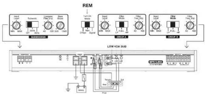
MPS 5.950 / Power And Signal Connections
6-CHANNEL LOW LEVEL RCA INPUT (FRONT + REAR + SUB)
flowchart
graph TD
    A["Input Input"] --> B["Subwoofer"]
    C["Input Signal"] --> B
    D["Input Level"] --> E["Low Chip Sub"]
    F["Input Level"] --> E
    G["Input Level"] --> E
    H["Input Level"] --> E
    I["Input Level"] --> E
    J["Input Level"] --> E
    K["Input Level"] --> E
    L["Input Level"] --> E
    M["Input Level"] --> E
    N["Input Level"] --> E
    O["Input Level"] --> E
    P["Input Level"] --> E
    Q["Input Level"] --> E
    R["Input Level"] --> E
    S["Input Level"] --> E
    T["Input Level"] --> E
    U["Input Level"] --> E
    V["Input Level"] --> E
    W["Input Level"] --> E
    X["Input Level"] --> E
    Y["Input Level"] --> E
    Z["Input Level"] --> E
    AA["Input Level"] --> E
    AB["Input Level"] --> E
    AC["Input Level"] --> E
    AD["Input Level"] --> E
    AE["Input Level"] --> E
    AF["Input Level"] --> E
    AG["Input Level"] --> E
    AH["Input Level"] --> E
    AI["Input Level"] --> E
    AJ["Input Level"] --> E
    AK["Input Level"] --> E
    AL["Input Level"] --> E
    AM["Input Level"] --> E
    AN["Input Level"] --> E
    AO["Input Level"] --> E
    AP["Input Level"] --> E
    AQ["Input Level"] --> E
    AR["Input Level"] --> E
    AS["Input Level"] --> E
    AT["Input Level"] --> E
    AU["Input Level"] --> E
    AV["Input Level"] --> E
    AW["Input Level"] --> E
    AX["Input Level"] --> E
    AY["Input Signal"] --> AZ["SUBwoofer"]
    BA["Output Signal"] --> BB["LOW Chip Sub"]
    BC["Memory"] --> BD["Low Chip Sub"]
    BE["Nature/Power Supply"] --> BF["MPE SSD"]

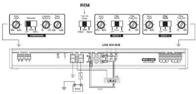
22
4-CHANNEL LOW LEVEL RCA INPUT (FRONT + SUB)
flowchart
graph TD
    A["SubMODER"] --> B["Input Level MIN MAX"]
    A --> C["Submoder"]
    A --> D["Longleaf Filter (LQ) 40 220 dB 10dB"]
    A --> E["Gain Filter"]
    A --> F["Turn On Maple"]
    A --> G["Output Signal"]
    H["LOW 4CH SUB"] --> I["Control Panel"]
    I --> J["Power Supply"]
    I --> K["Ground"]
    I --> L["Memory"]
    I --> M["Switch"]
    I --> N["Sub"]
    I --> O["Ground"]
    P["REM"] --> Q["Output Signal"]
    P --> R["Signal"]
    P --> S["Output Power"]
    P --> T["Output Current"]
    U["Group A"] --> V["Input Level MIN MAX"]
    U --> W["Output Level LP FULL UP"]
    U --> X["Output Power 40 400"]
    Y["Group B"] --> Z["Input Level MUN MAX"]
    Y --> AA["Output Level LP FULL UP"]
    Y --> AB["Output Power 40 400"]
4-CHANNEL LOW LEVEL RCA INPUT (FRONT + REAR)
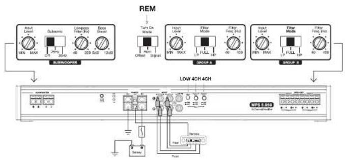
flowchart
graph TD
    A["Input Level"] --> B["SUBWOOFER"]
    C["Substrate"] --> B
    D["Lowpass Filter (Hz)"] --> B
    E["Boss Signal"] --> B
    B --> F["Turn On Mode"]
    F --> G["Offset Signal"]
    G --> H["Group A"]
    H --> I["Output Level"]
    I --> J["Group B"]
    J --> K["Output Level"]
    K --> L["Group B"]
    L --> M["LOW 40H 4CH"]
    M --> N["MPE 2.50D Display"]
    N --> O["Power Supply"]
    O --> P["Ground"]

MOREL PERFORMANCE SERIES AMPLIFIERS / Owner's ManualMOREL3PERFORM
2-CHANNEL LOW LEVEL RCA INPUT - FRONT ONLY
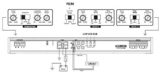
flowchart
graph TD
    A["REM"] --> B["Substation Module"]
    B --> C["Low 2CH Substation"]
    C --> D["Power Supply"]
    D --> E["Control Unit"]
    E --> F["Output"]
    style A fill:#f9f,stroke:#333
    style B fill:#ccf,stroke:#333
    style C fill:#cfc,stroke:#333
    style D fill:#fcc,stroke:#333
    style E fill:#ffc,stroke:#333
    style F fill:#fcc,stroke:#333
2-CHANNEL HIGH LEVEL RCA INPUT - FRONT ONLY
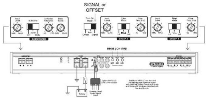
MPS 5.950 / Speaker Connections
5-CHANNEL STEREO/MONO - MODE
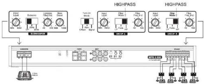
flowchart
graph TD
    subgraph Input_Layer
        A["Input Level MIN MAX"] --> B["Substrate"]
        B --> C["Leptase Filter Hid"]
        C --> D["Base Boost"]
        D --> E["BUXOOFER"]
    end

    subgraph HighPass_Layer
        F["Input Level MIN MAX"] --> G["Filter Mode T"]
        G --> H["Filter From Pin"]
        H --> I["Group A"]
        J["Input Level MIN MAX"] --> K["Filter Mode T"]
        K --> L["Filter From Pin"]
        L --> M["Group B"]
    end

    subgraph HighPass_HighPass_Layer
        N["Output Module"] --> O["MPE 9.550"]
        P["Signal"] --> Q["Ground"]
        R["Power"] --> S["Ground"]
    end

    style Input_Layer fill:#f9f,stroke:#333
    style HighPass_Layer fill:#bbf,stroke:#333
    style HighPass_HighPass_Layer fill:#dfd,stroke:#333
3-CHANNEL BRIDGED - STEREO/MONO MODE
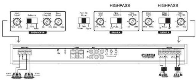
flowchart
graph TD
    subgraph BURWOOFER
        A["Input: MUN MAX 220V, Filter: 40 200 35N, NMR"]
        B["Turn On Mode: Brain Signal"]
        C["Output: Input Level: MUN MAX L PUL 1P, Filter Field: 40 400"]
        D["Group A"]
        E["Group B"]
    end
    subgraph HIGHPASS
        F["Input: MUN MAX L PUL 1P, Filter Field: 40 400"]
        G["Output: Input Level: MUN MAX L PUL 1P, Filter Field: 40 400"]
        H["Group A"]
        I["Group B"]
    end
    J["MPS 5.980"] --> K["Ground Interface"]
    style BURWOOFER fill:#f9f,stroke:#333
    style HIGHPASS fill:#ccf,stroke:#333
    style BURWOOFER fill:#fff,stroke:#333
    style HIGHPASS fill:#fff,stroke:#333
    style BURWOOFER fill:#fff,stroke:#333
    style HIGHPASS fill:#fff,stroke:#333
WARRANTY
Morel warrants this product to be free of defects in materials and workmanship for a period of two (2) years from the original date of purchase if installed by an authorized installer and one (1) year if sold over the counter or online. This warranty is not transferable and applies only to the original purchaser from an authorized Morel dealer in the USA only. Should service be necessary under this warranty for any reason due to manufacturing defect or malfunction, Morel will (at its discretion) repair or replace the defective product with new or remanufactured product at no charge. Damage caused by the following is not covered under warranty: accident, misuse, abuse, product modification or neglect, failure to follow installation instructions, unauthorized repair attempts, misrepresentations by the seller. This warranty does not cover incidental or consequential damages and does not cover the cost of removing or reinstalling the unit(s). Cosmetic damage due to accident or normal wear and tear is not covered under warranty.
INTERNATIONAL WARRANTIES:
Products purchased outside the USA are covered only by that country's Authorized Morel reseller and not by Morel. Consumers needing service or warranty information for these products must contact that country's reseller for information.
| MPS 5.950MPS 1. | |||
| RMS POWER @ 14V | |||
| 4 x 70w + 1 x 350w1 x 350w4 x 70w4 Ohm | |||
| 4 x 100w + 1 x 550w1 x 550A x 100w2 Ohm | |||
| Main ChannelsBridged, 4 ohm | 2 x 200w (Sub N/A)/N/A * 2 x 200w | ||
| 2 Ohms2 Ohms2 OhmsMinimum Impedance | |||
| SPECIFICATIONS | |||
| 0.15%0.05%THD | 0%0% (main), 0.15% (sub) | ||
| Frequency Response(main) | 10Hz 30kHz | N/A | 10Hz 30kHz |
| Frequency Response(sub) | N/A | 10-220Hz 10-220Hz | |
| S/N Ratio (Rated Power,A weightcd) | 100dB | 100dB | 100dB |
| Channel separation | 64dB | N/A | 84dB |
| Damping Factor >108/100 (main), >150 (sub)>150 | |||
| Selectable Input Range | Yes (x1/x2) | Yes (x1/x4) | Yes (x1/x2/x4) |
| Input Voltage Range(main, x1) | 200mV-5V | N/A | 200mV-5V |
| Input Voltage Range(main, x2) | 400mV-10V | 400mV-10VN/A | |
| Input Voltage Range(sub, x1) | N/A | 200mV-5V | 200mV-5V |
| Input Voltage Range(sub, x4) | 800mV-20VN/A | 800mV-20V | |
| PREAMP | |||
| Filters (main) | HP/LP, 40Hz-400Hz | N/A | HP/LP, 40Hz-400Hz |
| Filters (sub) | N/A | LP, 40-220Hz | LP, 40-220Hz |
| 12dB/OctaveCrossover Slopt2dB/Octave | 12dB/Octave | ||
| Subwoofer Level Control | No | YES, 0-20dB | YES, 0-20dB |
| Channel Input Mode NoYes (2/4 channel) | Yes (2/4/6 channel) | ||
| Subsonic Filter | No | SelectableOff/25Hz/35Hz | SelectableOff/25Hz/35Hz |
| Remote Level Control (sub) | N/A | Optional MPS-R1 | Optional MPS-R1 |
| TURN ON | |||
| YesDC Offset | Yes | Yes | |
| Signal Sensing | Yes | Yes | Yes |
| Ramicle | Yes | Yes | Yes |
| PHYSICAL SPECIFICATIONS | |||
| 2" (51mm)Height (ft) | 2" (51mm) | 2" (51mm) | |
| 6.7" (170mm)Width (W) | 6.7" (170mm) | 6.7" (170mm) | |
| Length (L) | 12.39" (314.5mm) | 8.44" (214.5mm) | 18.29" (≥64.5mm) |
| FUSERECOMMENDATION | *INLINE FUSE MUST BE USED WITHIN 16" (40cm) OF BATTERY | ||
| 80 Amp50 Amp40 Amp | |||
Morel constantly developing new technology and process to improve its products Morel reserves its right to modify specifications without notice. Images may not conform to specific product listed in this manual.

- SERIAL NUMBER
- Serial Number:
- PACKAGE CONTENT
- AVAILABLE ACCESSORIES
- PRACTICE SAFE SOUND!
- PRECAUTION
- MOUNTING THE AMPLIFIER
- PROTECTION
- PLANNING AND INSTALLATION
- MPS 4.400 / Features
- Power Status Indicator
- Protection Status Indicator
- Negative Chassis Ground Connector
- Remote Turn-On Connector
- +12VDC Power Connection
- 6-7. Left & Right Speaker Outputs
- 8-9. RCA Inputs
- High/Low Level Input Voltage Selector
- 2/4 Channel Input Mode Selector
- Turn On Mode Selector
- & 16. Input Sensitivity Controller
- & 17. Crossover Filter Selector
- & 18. Crossover Frequency Controller
- MPS 4.400 / Power And Signal Connections
- MPS 4.400 / Speaker Connections
- 2-CHANNEL BRIDGED MODE - STEREO HIGHPASS
- 2-CHANNEL BRIDGED MODE - LOWPASS SUBWOOFER
- MPS 1.550 / Features
- Subwoofer Outputs
- Remote Level Control
- High/Low Level Input Voltage Selector
- RCA Inputs
- Turn On Mode Selector
- Input Sensitivity Controller
- Subsonic Filter Selector
- Lowpass Frequency Controller
- Bass Boost Controller
- MPS 1.550 / Speaker Connections
- MPS 5.950 / Features
- 6-8. RCA Inputs
- High/Low Level Input Voltage Selector
- 2/4 Channel Input Mode Selector
- Subwoofer Input Mode Selector
- Subwoofer Outputs
- 13-14. Left & Right Speaker Outputs
- Input Sensitivity Controller
- Subsonic Filter Selector
- Lowpass Frequency Controller
- Bass Boost Controller
- Turn On Mode Selector
- & 23. Input Sensitivity Controller
- & 24. Crossover Filter Selector
- & 25. Crossover Frequency Controller
- MPS 5.950 / Power And Signal Connections
- MPS 5.950 / Speaker Connections
- WARRANTY
- INTERNATIONAL WARRANTIES:
Brand : Morel
Model : MPS 1.550
Category : Receiver