EP8204 - Router Netis - Free user manual and instructions
Find the device manual for free EP8204 Netis in PDF.

User questions about EP8204 Netis
0 question about this device. Answer the ones you know or ask your own.
Ask a new question about this device
Download the instructions for your Router in PDF format for free! Find your manual EP8204 - Netis and take your electronic device back in hand. On this page are published all the documents necessary for the use of your device. EP8204 by Netis.
USER MANUAL EP8204 Netis
natural_image
Pixelated grayscale squares on white background with no text or symbolsTable of contents
User Guide of netis PON OLT 7
1. Login to the graphical management interface ....7
1.1.Log into the management interface ....7
1.2. Management interface and usage ....8
2. System Information....10
2.1. Device Information....10
2.2. Slot Information....10
2.3. ONU Resister Information....10
2.4. ONU Register History....11
2.5. Illegal ONU 11
3. Switch Attribute....13
3.1. MAC Aging Time....13
3.2. Eth-Trunk ...... 13
3.3. Mirror 14
3.4. MAC Management....14
3.5. MAC Table ......15
4. Ethernet Port....16
4.1. Port Management....16
4.2. Port Attribute....16
4.3. Port Mode ....17
4.4. Port Function....18
4.5. Port QoS ....18
4.6. Port Isolation....19
5. VLAN....20
5.1.VLAN Stack 20
5.2.VLAN Table 20
5.3. Port VLAN....21
5.4.VLAN Translation....22
6. PON Global Attribute....23
6.1. Global Settings....23
6.2. Protection....23
6.3. Optical Power 24
- PON Slot Attribute....25
7.1. MAC Aging Time 25
7.2. DBA Mode....25
7.3. DBA Parameter .....26
7.4.MAC Table 26
7.5. MAC-TO-ONU....27
- PON Port Attribute ....28
8.1. Attribute....28
8.2. ONU Authentication Mode....28
8.3. ONU Authentication Table ......29
8.4. Health 29
- LLID Attribute 31
9.1. MAC Limit ....31
9.2.SLA 31
9.3.Encryption....32
9.4. LLID Information ....33
- ONU Global Attribute....33
10.1. Multicast Mode....33
10.2. Multicast Fastleave ....34
10.3.FEC 35
10.4.DBA 35
10.5. Holdover....36
10.6. Active PON Port....36
- ONU UNI Port Attribute ....38
11.1. Pause....38
11.2. Egress Rate Limit ....38
11.3. Ingress Policy....39
11.4.VLAN 39
11.5. Classification Mark ......40
11.6. Multicast VLAN....41
11.7. Multicast VLAN Strip 41
11.8. Maximum Multicast Group....42
11.9. Administration....43
11.10. Negotiate....43
11.11. Loop Detect ....44
- ONU Alarm....45
12.1. ONU Alarm Administration ....45
12.2. UNI Alarm Administration ....45
12.3. ONU Alarm Threshold....46
12.4. UNI Alarm Threshold....47
- ONU Global Information ....48
13.1. ONU SN 48
13.2.Firmware....48
13.3. Chip Information 49
13.4. Capacity 49
13.5. Multicast Fastleave Capacity....50
13.6. Multicast Fastleave State....50
13.7. FEC State 50
- ONU UNI Port State....51
14.1. Link State....51
14.2. Administration State ....51
14.3. Auto Negotiation ....52
14.4. Local Capability ....52
14.5. Declare Capability ....53
- ONU Maintenance....54
15.1. Reset ONU 54
15.2. Restart UNI Negotiation....54
- Multicast....55
16.1. Multicast Parameter Settings....55
16.2. Multicast Source....55
16.3. Static Multicast Group....56
16.4. Group Profile....56
16.5. Channel Limit and User Channel....57
16.6.CDR....58
16.7. Statistic Control....58
16.8. Channel Statistic....59
16.9. Channel Information....59
16.10. Specify User Information....59
16.11. Specify Channel Information....60
- STP....61
17.1. STP Bridge Settings....61
17.2. STP Port Settings....61
17.3. STP Bridge State....62
17.4. STP Port State....62
- DHCP....64
18.1.Option82....64
18.2. Statistics....64
- PPPoE....66
19.1. PPPoE+ 66
19.2. Statistics....66
- Alarm....68
20.1. Alarm Redefine ......68
20.2. Alarm Mask....68
20.3. Alarm Filtering Time 69
20.4. Alarm Definition Table ......69
20.5. Current Alarm....70
20.6. History Alarm....71
20.7. Auto Alarm ....71
- Statistics Management....73
21.1. Statistic Task 73
21.2. Statistic Object....73
21.3.Time Template....74
21.4. Ethernet port Statistics ....74
21.5. PON Port Statistics ....75
21.6. LLID Statistics....76
21.7. Ethernet Port Period Statistics ....77
21.8. PON Port Period Statistics....78
21.9. LLID Period Statistics ......78
21.10. ONU Performance Analysis....78
21.11. PON Performance Analysis ......79
22. System Maintenance....81
22.1. Network Parameter 81
22.2. FTP Service....81
22.3. Overload Threshold....82
22.4. Clock....82
22.5. Reset....83
22.6.Add User 83
22.7. Delete User....83
22.8. Delete User....84
22.9. Log....84
22.10. Upgrade 85
22.11.Restore....86
User Guide of netis PON OLT
1. Login to the graphical management interface
1.1.Log into the management interface
- Open a web browser and type http://192.168.2.201 into the URL bar. Press Enter as shown in Figure (1-1).

text_image
http://192.168.2.201Figure 1-1
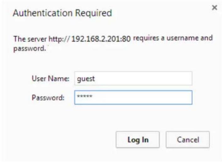
- In a pop-up window type "guest" as the username and password respectively and click Log In or OK as shown in Figure (1-2). (Prompt: Enter username "guest" and password "guest" to login as a normal user. Enter username "root" and password "epondevp" to login as an administrator.)
text_image
Authentication Required The server http://192.168.2.201:80 requires a username and password. User Name: guest Password: ***** Log In CancelFigure1-2
1.2. Management interface and usage
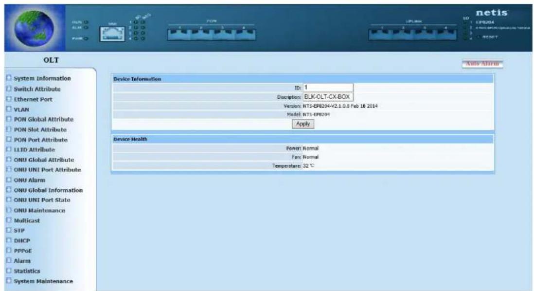
- Enter into main interface after login, as shown in following figure.
BLK-C1 front panel structure chart is shown at top of page, the function menu interface has a tree structure as shown on the left of the page. There is a block of region in the middle of the page, which is also the main window displays configuration and query information, as shown in Figure (1-3).
text_image
OLT System Information Switch Attribute Ethernet Port VLAN PON Global Attribute PON Slot Attribute PON Port Attribute LLTD Attribute ONU Global Attribute ONU UNI Port Attribute ONU Alarm ONU Global Information ONU UNI Port State ONU Maintenance Multicast STP DHCP PPPoE Alarm Statistics System Maintenance Device Information ID: 1 Description: BLK-OLT-CX-BOX Version: NT5-EPB204+V2.1.0.8 Feb 18 2014 Model: NT5-EPB204 Apply Device Health Power: Normal Fan: Normal Temperature: 32 °CFigure 1-3
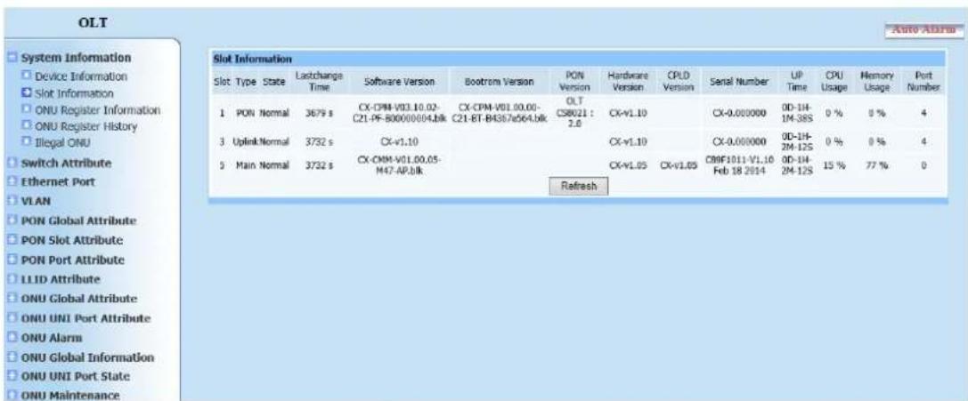
- The function menu shows the directory tree structure divided into two layers. Click any main item to display the item information. Select the desired item, the main window will switch to item configuration or query display page.
Function menu is shown as Figure (1-4).
text_image
OLT System Information Device Information Slot Information ONU Register Information ONU Register History Illegal ONU Switch Attribute Ethernet Port VLAN PON Global Attribute PON Slot Attribute PON Port Attribute LLID Attribute ONU Global Attribute ONU UNI Port Attribute ONU Alarm ONU Global Information ONU UNI Port State ONU Maintenance Slot Information Slot Type State Lastchange Time Software Version Bootrom Version PON Version Hardware Version CPLD Version Serial Number UP Time CPU Usage Memory Usage Port Number 1 PON Normal 3679 s CX-CPM-V01.10.02-C21-PF-B00000004.blk CX-CPM-V01.00.00-C21-BT-B4387a564.blk OLTCSB021: 2.0 CX-V1.10 CX-0.000000 0D-1H-1M-38S 0 % 8 % 4 3 Uplink Normal 3732 s CX-V1.10 CX-V1.10 CX-0.000000 0D-1H-2M-12S 0 % 0 % 4 5 Main Normal 3732 s CX-CMM-V01.00.05-M47-AP.blk CX-V1.05 CX-V1.05 C99F1011-V1.10 0D-1H-2M-12S 15 % 77 % 0 RefreshFigure 1-4
2. System Information
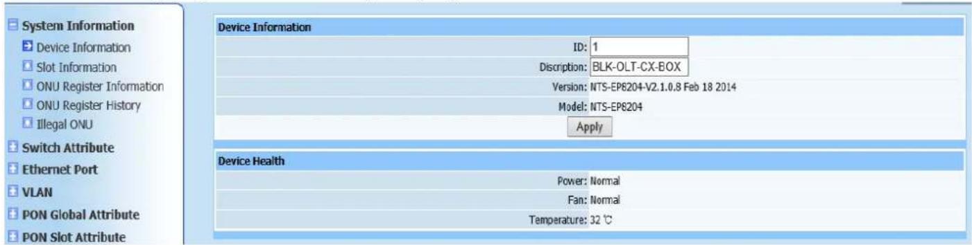
2.1. Device Information
Query page is shown as Figure (2-1):
text_image
System Information Device Information ID: 1 Discription: BLK-OLT-CX-BOX Version: NTS-EP8204-V2.1.0.8 Feb 18 2014 Model: NTS-EP8204 Apply Device Health Power: Normal Fan: Normal Temperature: 32 °CFigure 2-1
This query page is mainly to find OLT network element information, including equipment ID, equipment name, equipment version, power state, fan state and environment temperature.
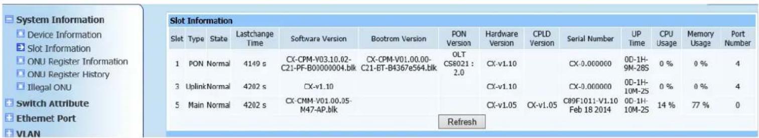
2.2. Slot Information
Query page is shown as Figure (2-2):
text_image
Slot Information Slot Type State Lastchange Software Version Bootrom Version PON Version Hardware Version CPLD Version Serial Number UP Time CPU Usage Memory Usage Port Number 1 PON Normal 4149 s CX-CPM-V03.10.02-C21-PF-B00000004.blk CX-CPM-V01.00.00-C21-ET-B4367e564.blk OLT CS8021 : 2.0 CX-v1.10 CX-0.000000 0D-1H-9M-28S 0 % 0 % 4 3 UplinkNormal 4202 s CX-v1.10 CX-v1.10 CX-0.000000 0D-1H-10M-2S 0 % 0 % 4 5 Main Normal 4202 s CX-CMM-V01.00.05-M47-AP.blk CX-v1.05 CX-v1.05 C89F1011-V1.10 Feb 18 2014 0D-1H-10M-2S 14 % 77 % 0 RefreshFigure 2-2
This query page is mainly to find OLT module information, including PON module, uplink module and control module.
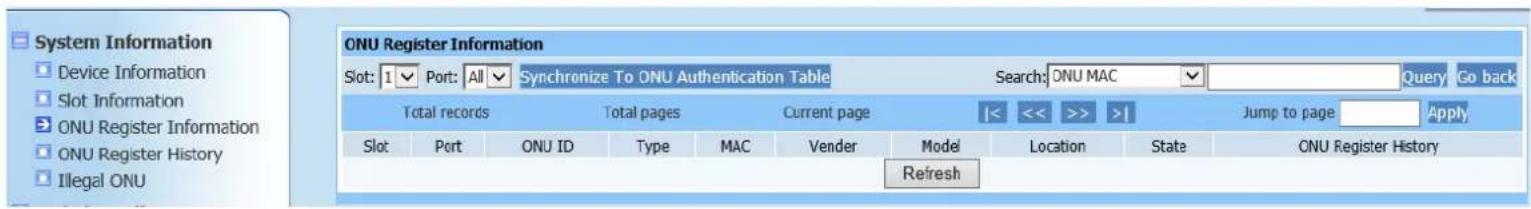
2.3. ONU Resister Information
Query page is shown as Figure (2-3):
text_image
System Information Device Information Slot Information ONU Register Information ONU Register History Illegal ONU ONU Register Information Slot: 1 Port: All Synchronize To ONU Authentication Table Search: ONU MAC Query Go back Total records Total pages Current page |<< >> >| Jump to page Apply Slot Port ONU ID Type MAC Vendor Model Location State ONU Register History RefreshFigure 2-3
This query page is mainly to find all registered ONU information of OLT, in which ONUs registered under each PON are labeled in detail, including ONU type, MAC address, manufacturer ID and ONU model.
Automatically add authentication. ONU can be all registered in un- authentication mode. If registered ONU is required to configure to authentication mode, select required modules and ports (if none is selected, authentication will add to all PON ports of OLT by default), then click Auto Add Authentication, corresponding PON ports of OLT will generate registered ONU authentication table (view relevant information via "ONU Authentication Table" in "PON Port Attributes").
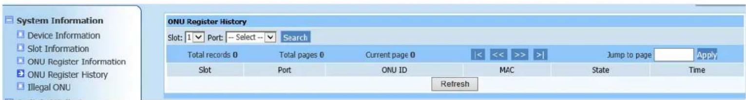
2.4. ONU Register History
Query page is shown as Figure (2-4):
text_image
System Information Device Information Slot Information ONU Register Information ONU Register History Illegal ONU ONU Register History Slot: 1▼ Port: — Select —▼ Search Total records 0 Total pages 0 Current page 0 |< << >> >| Jump to page Apply Slot Port ONU ID MAC State Time RefreshFigure 2-5
This query page is mainly to find registered ONU history on OLT.
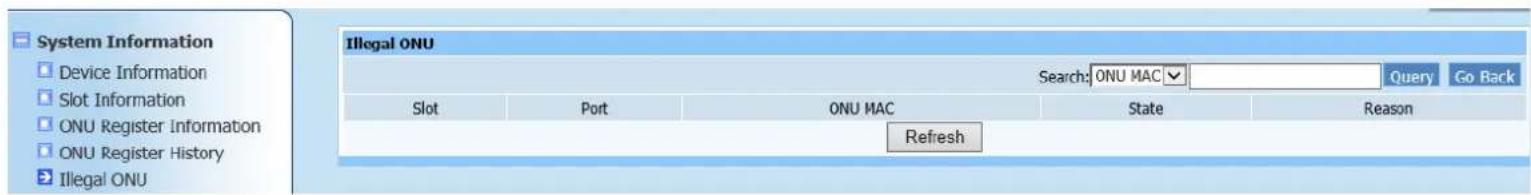
2.5. Illegal ONU
Query page is shown as Figure (2-5):
text_image
System Information Device Information Slot Information ONU Register Information ONU Register History Illegal ONU Illegal ONU Search: ONU MAC Query Go Back Slot Port ONU MAC State Reason RefreshFigure 2-5
This query page is mainly to find illegally registered ONU information on OLT.
3. Switch Attribute
3.1. MAC Aging Time
Web configuration page is shown as Figure (3-1):

text_image
System Information Switch Attribute MAC Aging Time Eth-Trunk MAC Aging Time: 300 [0,1000000]s ApplyFigure 3-1
This page is to configure MAC aging time. After configuration is completed, MAC address will be auto-aging in a period of time [0 1000000] if no address is forwarded, it shows when aging time is 0, no aging time exists and this is only used for test.
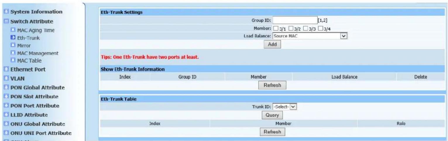
3.2. Eth-Trunk
Web configuration page is shown as Figure (3-2):
text_image
System Information Switch Attribute MAC Aging Time Eth-Trunk Mirror MAC Management MAC Table Ethernet Port VLAN PON Global Attribute PON Slot Attribute PON Port Attribute LLID Attribute ONU Global Attribute ONU UNI Port Attribute Eth-Trunk Settings Group ID: [1,2] Member: □3/1 □3/2 □3/3 □3/4 Load Balance: Source MAC Add Tips: One Eth-Trunk have two ports at least. Show Eth-Trunk Information Index Group ID Member Load Balance Delete Refresh Eth-Trunk Table Trunk ID: -Select- Query Index Member Role RefreshFigure 3-2
This Web configuration page is to add static TRUNK group. Click Add to refresh page after configuration is completed. The following TRUNK group displays static TRUNK group information which has been added.
If static TRUNK group information query is required, enter ID in corresponding
message field and click Query button, specific information displays in static TRUNK group information field.
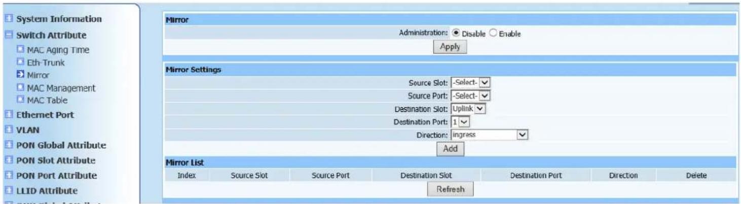
3.3. Mirror
Web configuration page is shown as Figure (3-3):
text_image
System Information Switch Attribute MAC Aging Time Eth-Trunk Mirror MAC Management MAC Table Ethernet Port VLAN PON Global Attribute PON Slot Attribute PON Port Attribute LLID Attribute Mirror Administration: ● Disable ○ Enable Apply Mirror Settings Source Slot: -Select- Source Port: -Select- Destination Slot: Uplink Destination Port: 1 Direction: ingress Add Mirror List Index Source Slot Source Port Destination Slot Destination Port Direction Delete RefreshFigure 3-3
1. Overview
Mirroring is to mirror input/output message of certain port to another port. Output port is usually connected to network protocol analyzer. This function is often used to diagnose network failure and analyze network flow.
2. Configuration instructions
Enable Administration configuration, and click Apply, then configure port mirroring in Mirror Settings field. Click Add to automatically refresh page after configuration is completed, the added information displays in Mirror List field. Check if the information is configured as required.
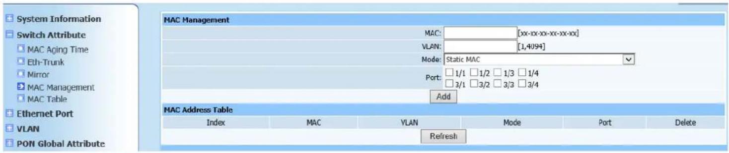
3.4. MAC Management
Web configuration page is shown as Figure (3-4):
text_image
System Information Switch Attribute MAC Aging Time Eth-Trunk Mirror MAC Management MAC Table Ethernet Port VLAN PON Global Attribute MAC Management MAC: [xx-xx-xx-xx-xx-xx] VLAN: [1,4094] Mode: Static MAC Port: 1/1 1/2 1/3 1/4 3/1 3/2 3/3 3/4 Add MAC Address Table Index MAC VLAN Mode Port Delete RefreshFigure 3-4
This page is to configure port MAC filtering. The purpose is disallow specific MAC addresses to pass the configured ports.
Enter as required in the following format in rectangle input field next to MAC. Enter VLAN of MAC address in its own configuration item. Configure filtering mode according to your need and select port to be configured, click Add to automatically refresh page after configuration is completed, added information displays in MAC filtering table.
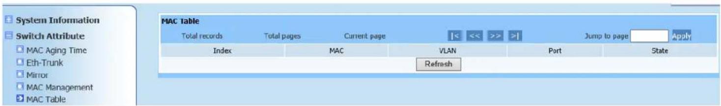
3.5. MAC Table
Query page is shown as Figure (3-5):
text_image
System Information Switch Attribute MAC Aging Time Eth-Trunk Mirror MAC Management MAC Table MAC Table Total records Total pages Current page |<< >> >| Jump to page Apply Index MAC VLAN Port State RefreshFigure 3-5
This page is to query MAC address forwarding table of uplink port and accessory MAC VLAN information.
4. Ethernet Port
4.1. Port Management
Web configuration page is shown as Figure (4-1):
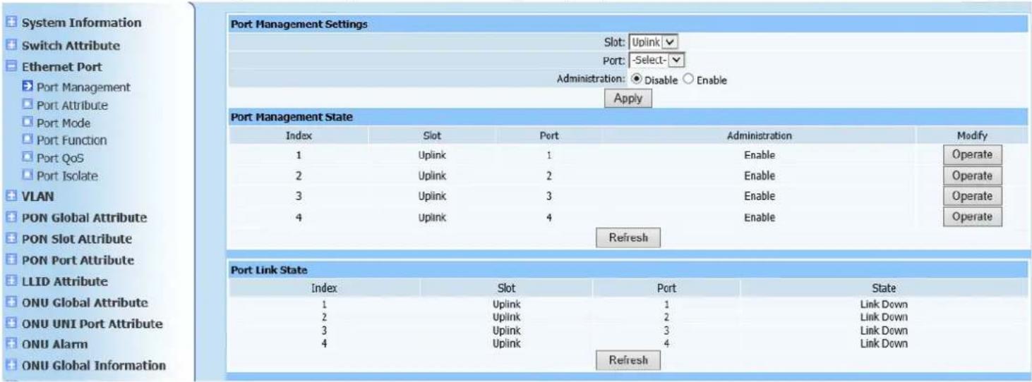
text_image
System Information Switch Attribute Ethernet Port Port Management Port Attribute Port Mode Port Function Port QoS Port Isolate VLAN PON Global Attribute PON Slot Attribute PON Port Attribute LLID Attribute ONU Global Attribute ONU UNI Port Attribute ONU Alarm ONU Global Information Port Management Settings Slot: Uplink Port: -Select- Administration: Disable Enable Apply Port Management State Index Slot Port Administration Modify 1 Uplink 1 Enable Operate 2 Uplink 2 Enable Operate 3 Uplink 3 Enable Operate 4 Uplink 4 Enable Operate Refresh Port Link State Index Slot Port State 1 Uplink 1 Link Down 2 Uplink 2 Link Down 3 Uplink 3 Link Down 4 Uplink 4 Link Down RefreshFigure 4-1
Port Management Setting is to configure Administration status of uplink port as required. Click Apply to automatically refresh Port Management State page after configuration is completed. Check if the displayed configuration information is as required.
4.2. Port Attribute
Web configuration page is shown as Figure (4-2):
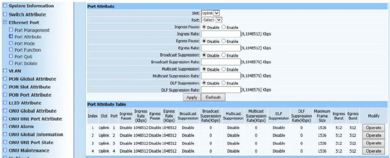
text_image
System Information Switch Attribute Ethernet Port Port Management Port Attribute Port Mode Port Function Port QoS Port Isolate VLAN PON Global Attribute PON Slot Attribute PON Port Attribute LLID Attribute ONU Global Attribute ONU UNI Port Attribute ONU Alarm ONU Global Information ONU UNI Port State ONU Maintenance Multiport Port Attribute Table Slot: Uplink Port: -Select- Ingress Pause: Disable Enable Ingress Rate: [0,1048512] Kbps Egress Pause: Disable Enable Egress Rate: [0,1048512] Kbps Broadcast Suppression: Disable Enable Broadcast Suppression Rate: [0,1048576] Kbps Multicast Suppression: Disable Enable Multicast Suppression Rate: [0,1048576] Kbps DLF Suppression: Disable Enable DLF Suppression Rate: [0,1048576] Kbps Apply Refresh Port Attribute Table Index Slot Port Ingress Ingress Multicast Multicast DLF Maximum Ingress Modify Ingress Rate Egress Egress Broadcast Suppression Suppression Multicast Suppression Suppression Suppression Suppression Suppression Suppression Suppression Suppression Suppression Suppression Suppression Suppression Suppression Suppression Suppression Suppression Suppression Suppression Suppression Suppression Suppression Suppression Suppression Suppression Suppression Suppression Suppression Suppression Suppression Suppression Suppression Suppression Suppression Suppression Suppression Suppression Suppression Suppression Suppression Suppression Suppression Suppression Suppression Suppression Suppression Suppression Suppression Suppression Suppression Suppression Suppressor 1 Uplink 1 Disable 1048512 Disable 1048512 Disable 0 Disable 0 Disable 0 1536 512 512 Operate 2 Uplink 2 Disable 1048512 Disable 1048512 Disable 0 Disable 0 Disable 0 1536 512 512 Operate 3 Uplink 3 Disable 1048512 Disable 1048512 Disable 0 Disable 0 Disable 0 1536 512 512 Operate 4 Uplink 4 Disable 1048512 Disable 1048512 Disable 0 Disable 0 Disable 0 1536 512 512 OperateFigure 4-2
This page is to configure flow control of uplink port as required in configure prompt page. Click Apply to refresh port attribute list. Check if the displayed information is as required to add.
4.3. Port Mode
Web configuration page is shown as Figure (4-3):
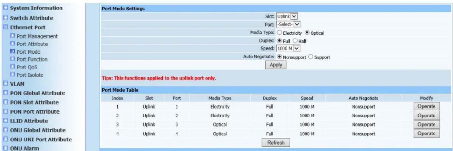
text_image
System Information Switch Attribute Ethernet Port Port Management Port Attribute Port Mode Port Function Port QoS Port Isolate VLAN PON Global Attribute PON Slot Attribute PON Port Attribute LLID Attribute ONU Global Attribute ONU UNI Port Attribute ONU Alarm Port Mode Settings Slot: Uplink Port: -Select- Media Type: ○ Electricity ● Optical Duplex: ● Full ○ Half Speed: 1000 M Auto Negotiate: ● Nonsupport ○ Support Apply Tips: This functions applied to the uplink port only. Port Mode Table Index Slot Port Media Type Duplex Speed Auto Negotiate Modify 1 Uplink 1 Electricity Full 1000 M Nonsupport Operate 2 Uplink 2 Electricity Full 1000 M Nonsupport Operate 3 Uplink 3 Optical Full 1000 M Nonsupport Operate 4 Uplink 4 Optical Full 1000 M Nonsupport Operate RefreshFigure 4-3
This page is mainly to configure media type, duplex mode, speed of uplink port and whether self-adaption information is supported. Configure uplink port mode
according to your needs, and click Apply to automatically refresh port mode list after configuration is completed. Check if the displayed configuration information is as required.
4.4. Port Function
Web configuration page is shown as Figure (4-4):
text_image
System Information Switch Attribute Ethernet Port Port Management Port Attribute Port Mode Port Function Port QoS Port Isolate VLAN PON Global Attribute PON Slot Attribute PON Port Attribute LLID Attribute ONU Global Attribute ONU UNI Port Attribute ONU Alarm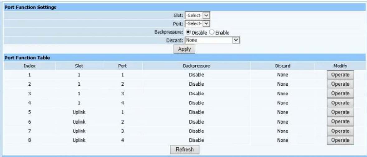
text_image
Port Function Settings Slot: Select Port: Select- Backpressure: ● Disable ○ Enable Discard: None Apply Port Function Table Index Slot Port Backpressure Discard Modify 1 1 1 Disable None Operate 2 1 2 Disable None Operate 3 1 3 Disable None Operate 4 1 4 Disable None Operate 5 Uplink 1 Disable None Operate 6 Uplink 2 Disable None Operate 7 Uplink 3 Disable None Operate 8 Uplink 4 Disable None Operate RefreshFigure 4-4
This page is to configure back-pressure administration of ports. If you need to limit packets received on ports, configure back-pressure administration as activated state to specific ports and select required mode in discard mode. Click Apply to automatically refresh port function list after configuration is completed. Check if the displayed configuration information is as required.
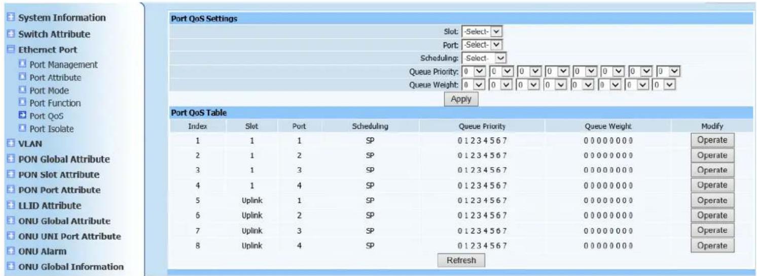
4.5. Port QoS
Web configuration page is shown as Figure (4-5):
text_image
System Information Switch Attribute Ethernet Port Port Management Port Attribute Port Mode Port Function Port QoS Port Isolate VLAN PON Global Attribute PON Slot Attribute PON Port Attribute LLID Attribute ONU Global Attribute ONU UNI Port Attribute ONU Alarm ONU Global Information Port QoS Settings Slot: -Select- Port: -Select- Scheduling: Select- Queue Priority: 0 0 0 0 0 0 0 0 0 0 0 0 0 0 Queue Weight: 0 0 0 0 0 0 0 0 0 0 0 0 0 Apply Port QoS Table Index Slot Port Scheduling Queue Priority Queue Weight Modify 1 1 1 SP 0 1 2 3 4 5 6 7 0 0 0 0 0 0 0 Operate 2 1 2 SP 0 1 2 3 4 5 6 7 0 0 0 0 0 0 0 Operate 3 1 3 SP 0 1 2 3 4 5 6 7 0 0 0 0 0 0 0 Operate 4 1 4 SP 0 1 2 3 4 5 6 7 0 0 0 0 0 0 0 Operate 5 Uplink 1 SP 0 1 2 3 4 5 6 7 0 0 0 0 0 0 0 Operate 6 Uplink 2 SP 0 1 2 3 4 5 6 7 0 0 0 0 0 0 0 Operate 7 Uplink 3 SP 0 1 2 3 4 5 6 7 0 0 0 0 0 0 0 Operate 8 Uplink 4 SP 0 1 2 3 4 5 6 7 0 0 0 0 0 0 0 Operate RefreshFigure 4-5
This configuration Web page is to configure QoS scheduling of ports. Select modules and ports required to configure according to demand in which there are three algorithms (sp scheduling, wrr scheduling and sp+wrr scheduling), then configure queue priority and queue Weight, click Apply after configuration is finished. Port Qos scheduling list will automatically refresh. Check displayed information is identical as required configuration.
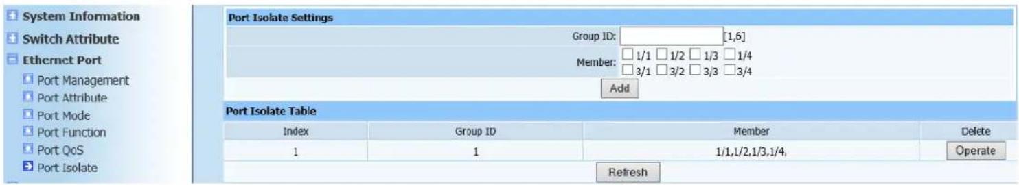
4.6. Port Isolation
Web configuration page is shown as Figure (4-6):
text_image
System Information Switch Attribute Ethernet Port Port Management Port Attribute Port Mode Port Function Port QoS Port Isolate Port Isolate Settings Group ID: [1,6] Member: 1/1 1/2 1/3 1/4 3/1 3/2 3/3 3/4 Add Port Isolate Table Index Group ID Member Delete 1 1 1/1,1/2,1/3,1/4, Operate RefreshFigure 4-6
This page is to configure OLT port isolation. Select ports need to isolate from each other, click Add button. After ports are successfully added, port isolation list displays configured information to verify the ports has configured correctly. If not, delete and re-configure.
5. VLAN
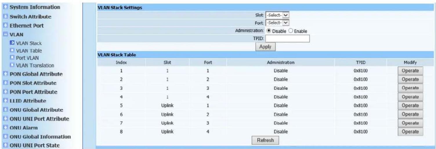
5.1. VLAN Stack
Web configuration page is shown as Figure (5-1):
text_image
System Information Switch Attribute Ethernet Port VLAN VLAN Stack VLAN Table Port VLAN VLAN Translation PON Global Attribute PON Slot Attribute PON Port Attribute LLID Attribute ONU Global Attribute ONU UNI Port Attribute ONU Alarm ONU Global Information ONU UNI Port State VLAN Stack Settings Slot: -Select- Port: -Select- Administration: ● Disable ○ Enable TPID: Apply VLAN Stack Table Index Slot Port Administration TPID Modify 1 1 1 Disable 0x8100 Operate 2 1 2 Disable 0x8100 Operate 3 1 3 Disable 0x8100 Operate 4 1 4 Disable 0x8100 Operate 5 Uplink 1 Disable 0x8100 Operate 6 Uplink 2 Disable 0x8100 Operate 7 Uplink 3 Disable 0x8100 Operate 8 Uplink 4 Disable 0x8100 Operate RefreshFigure 5-1
This page is to configure multiple VLAN Stack configuration status.
Select modules and ports according to page prompting, and select
Administration status. TPID is hexadecimal format, default to 0x8100. Click
Apply to automatically refresh multiple VLAN stack list after configuration is completed. Check if the displayed configuration information is as required.
5.2. VLAN Table
Web configuration page is shown as Figure (5-2):
text_image
System Information Switch Attribute Ethernet Port VLAN VLAN Stack VLAN Table Port VLAN VLAN Translation PON Global Attribute PON Slot Attribute PON Port Attribute LLID Attribute ONU Global Attribute ONU UNI Port Attribute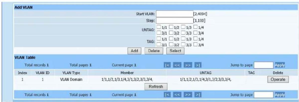
text_image
Add VLAN Start VLAN: ________ [2,4094] Step: ________ [1,100] UNTAG: 1/1 1/2 1/3 1/4 3/1 3/2 3/3 3/4 TAG: 1/1 1/2 1/3 1/4 3/1 3/2 3/3 3/4 Add Delete Select VLAN Table Total records 1 Total pages 1 Current page 1 |<< >> >>| Jump to page Apply Index VLAN ID VLAN Type Member UNTAG TAG Delete 1 1 VLAN Domain 1/1,1/2,1/3,1/4,3/1,3/2,3/3,3/4, 1/1,1/2,1/3,1/4,3/1,3/2,3/3,3/4, Refresh Total records 1 Total pages 1 Current page 1 |<< >> >>| Jump to page ApplyFigure 5-2
This page is to configure port VLAN and VLAN domain. Initial ID configure of VLAN is PON port VLAN domain's starting ID and VLAN's step size is vlan range. VLAN types divide into port VLAN and VLAN domain. Select port members and then select TAG string method. Click Apply to automatically refresh multiple VLAN table after configuration is completed. Check if the displayed configuration information is as required.
5.3. Port VLAN
Web configuration page is shown as Figure (5-3):
text_image
System Information Switch Attribute Ethernet Port VLAN VLAN Stack VLAN Table Port VLAN VLAN Translation PON Global Attribute PON Slot Attribute PON Port Attribute LLID Attribute ONU Global Attribute ONU UNI Port Attribute ONU Alarm ONU Global Information ONU UNI Port State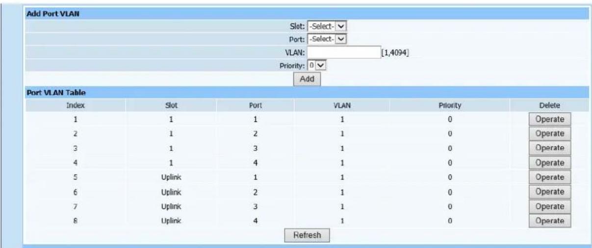
text_image
Add Port VLAN Slot: -Select- Port: -Select- VLAN: [1,4094] Priority: 0 Add Port VLAN Table Index Slot Port VLAN Priority Delete 1 1 1 1 0 Operate 2 1 2 1 0 Operate 3 1 3 1 0 Operate 4 1 4 1 0 Operate 5 Uplink 1 1 0 Operate 6 Uplink 2 1 0 Operate 7 Uplink 3 1 0 Operate 8 Uplink 4 1 0 Operate RefreshFigure5-3
This page is to configure port VLAN. Select modules and ports, enter port
VLAN's size in VLAN ID field, then select priority. Click Add to automatically refresh VLAN table after configuration is completed. Check if the displayed configuration information is as required.
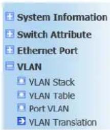
5.4. VLAN Translation
Web configuration page is shown as Figure (5-4):
text_image
System Information Switch Attribute Ethernet Port VLAN VLAN Stack VLAN Table Port VLAN VLAN Translation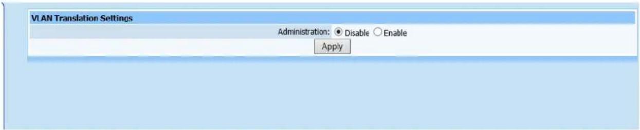
text_image
VLAN Translation Settings Administration: ● Disable ○ Enable ApplyFigure 5-4
This page is to configure VLAN Translation Administration. It's Disabled in default.
6. PON Global Attribute
6.1. Global Settings
Web configuration page is shown as Figure (6-1):
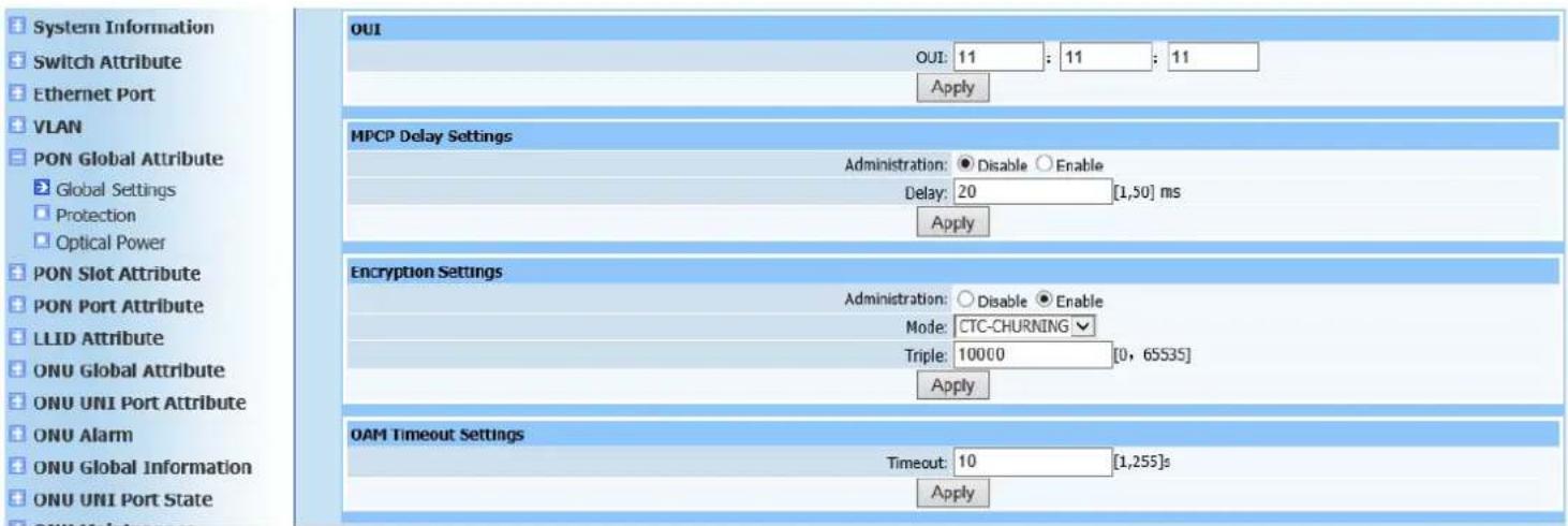
text_image
System Information Switch Attribute Ethernet Port VLAN PON Global Attribute Global Settings Protection Optical Power PON Slot Attribute PON Port Attribute LLID Attribute ONU Global Attribute ONU UNI Port Attribute ONU Alarm ONU Global Information ONU UNI Port State OUI OUI: 11 : 11 : 11 Apply MPCP Delay Settings Administration: Disable Enable Delay: 20 [1,50] ms Apply Encryption Settings Administration: Disable Enable Mode: CTC-CHURNING Triple: 10000 [0, 65535] Apply OAM Timeout Settings Timeout: 10 [1,255]s ApplyFigure 6-1
This page is to configure operator identifier, multi-point control protocol Administration (disable or enable), MPCP discovery delay time, PON encryption Administration (disable or enable), encryption mode, key update time and OAM timeout period.
6.2. Protection
Web configuration page is shown as Figure (6-2):
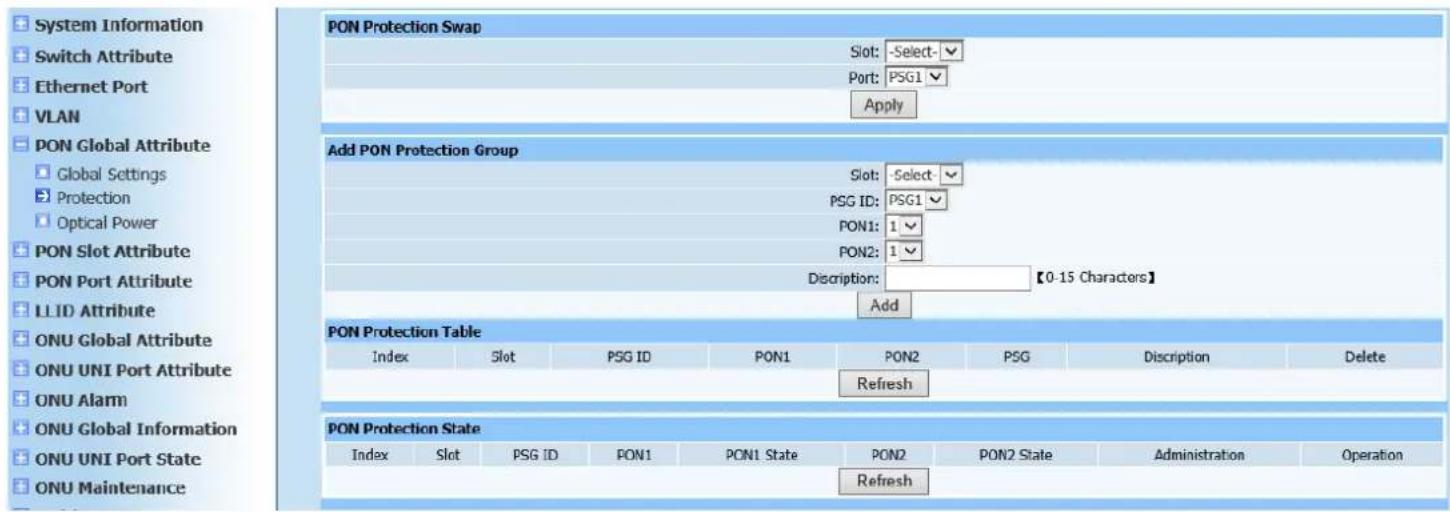
text_image
System Information Switch Attribute Ethernet Port VLAN PON Global Attribute Global Settings Protection Optical Power PON Slot Attribute PON Port Attribute LL ID Attribute ONU Global Attribute ONU UNI Port Attribute ONU Alarm ONU Global Information ONU UNI Port State ONU Maintenance PON Protection Swap Slot: -Select-✓ Port: PSG1 ✓ Apply Add PON Protection Group Slot: -Select-✓ PSG ID: PSG1 ✓ PON1: 1 ✓ PON2: 1 ✓ Discription: 【0-15 Characters】 Add PON Protection Table Index Slot PSG ID PON1 PON2 PSG Discrption Delete Refresh PON Protection State Index Slot PSG ID PON1 PON1 State PON2 PON2 State Administration Operation RefreshFigure 6-2
This page is to configure PON modules. If configuration is required, all PON ports of PON modules must be in unmanaged status (all PON ports Administration are disabled), then configure as required.
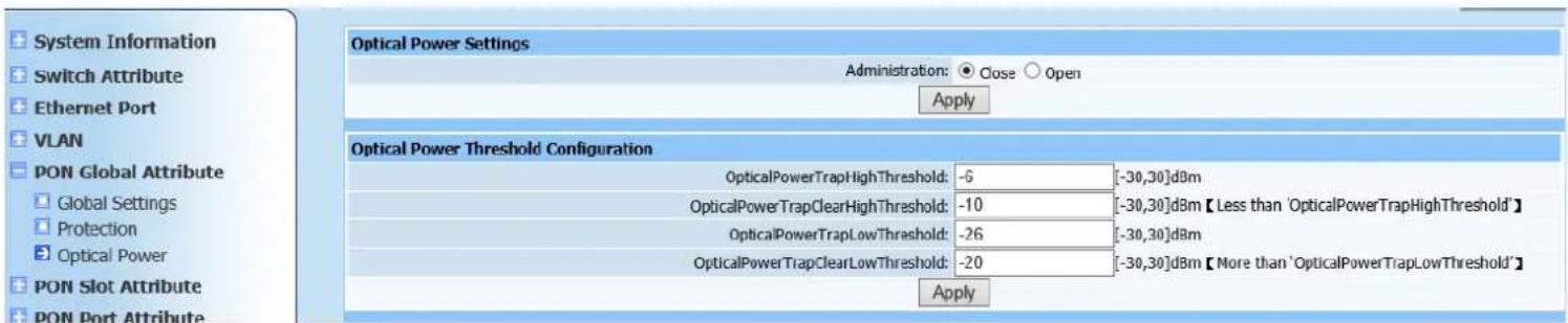
6.3. Optical Power
Web configuration page is shown as Figure (6-3):
text_image
System Information Switch Attribute Ethernet Port VLAN PON Global Attribute Global Settings Protection Optical Power PON Slot Attribute PON Port Attribute Optical Power Settings Administration: Close Open Apply Optical Power Threshold Configuration OpticalPowerTrapHighThreshold: -6 [-30,30]dBm OpticalPowerTrapClearHighThreshold: -10 [-30,30]dBm【Less than 'OpticalPowerTrapHighThreshold'】 OpticalPowerTrapLowThreshold: -26 [-30,30]dBm OpticalPowerTrapClearLowThreshold: -20 [-30,30]dBm【More than 'OpticalPowerTrapLowThreshold'】 ApplyFigure 6-3
This page is to configure optical power. Configure optical power detector switch control as enable/disable, then configure the following parameters.
7. PON Slot Attribute
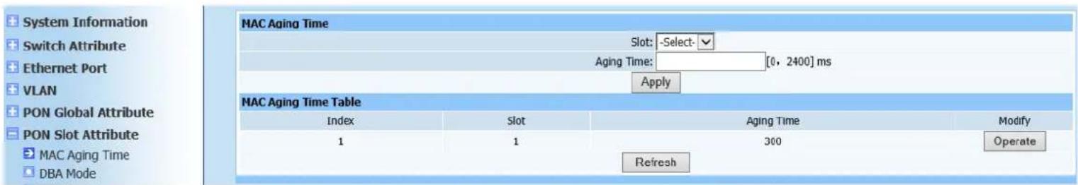
7.1. MAC Aging Time
Web configuration page is shown as Figure (7-1):
text_image
System Information Switch Attribute Ethernet Port VLAN PON Global Attribute PON Slot Attribute MAC Aging Time DBA Mode MAC Aging Time Table Index Slot Aging Time Modify 1 1 300 Operate RefreshFigure 7-1
This page is to configure module aging time. Select modules required to configure and its aging time, ranging [0.2400] and default to 300ms. Click Apply button after configuration is completed. MAC aging time-table will automatically refresh. Check displayed information is identical as required.
7.2. DBA Mode
Web configuration page is shown as Figure (7-2):

text_image
System Information Switch Attribute Ethernet Port VLAN PON Global Attribute PON Slot Attribute MAC Aging Time DBA Mode DBA Parameter DBA Mode Settings Slot: -Select- Mode: Hardware Algorithm: WORK CONSERV Apply DBA Mode Table Index Slot Mode Algorithm Modify 1 1 Hardware Dynamic CBR Operate RefreshFigure 7-2
This page is to configure PON module DBA modes. DBA modes divide into hardware DBA, software DBA, hardware DBA and dynamic cycling time adjustment and software DBA and dynamic cycling time adjustment. DBA algorithms divide into three types of <maxMinWorkConserv|
maxMinNonWorkConserv |maxMinCbr>. Click Apply to automatically refresh DBA mode table after configuration is completed. Check if the displayed configuration information is as required.
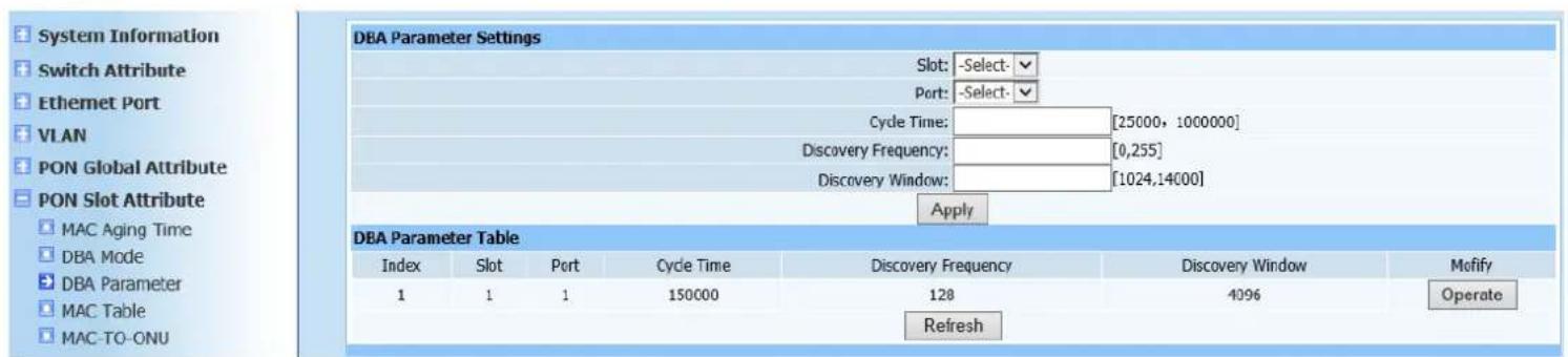
7.3. DBA Parameter
Web configuration page is shown as Figure (7-3):
text_image
System Information Switch Attribute Ethernet Port VLAN PON Global Attribute PON Slot Attribute MAC Aging Time DBA Mode DBA Parameter MAC Table MAC-TO-ONU DBA Parameter Settings Slot: -Select: Port: -Select: Cycle Time: [25000, 1000000] Discovery Frequency: [0,255] Discovery Window: [1024,14000] Apply DBA Parameter Table Index Slot Port Cycle Time Discovery Frequency Discovery Window Motify 1 1 1 150000 128 4096 Operate RefreshFigure 7-3
This page is to configure DBA parameters, including DBA cycle time, DBA discovery frequency and DBA discovery window. Select required modules and PON ports, type configured value 1024TQ(TQ=16ns) in corresponding DBA parameter fields. Click Apply to automatically refresh the DBA parameter table after configuration is completed. Check if the displayed configuration information is as required.
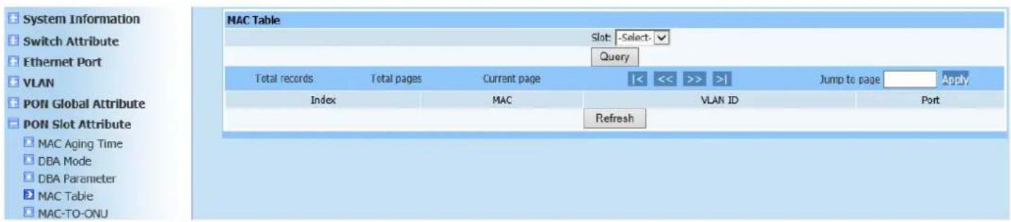
7.4. MAC Table
Query page is shown as Figure (7-4):
text_image
System Information Switch Attribute Ethernet Port VLAN PON Global Attribute PON Slot Attribute MAC Aging Time DBA Mode DBA Parameter MAC Table MAC-TO-ONJ MAC Table Slot: -Select- Query Total records Total pages Current page |<< >> | Jump to page Apply Index MAC VLAN ID Port RefreshFigure7-4
This query page is used to find MAC forwarding table of PON modules.
7.5. MAC-TO-ONU
Query page is shown as Figure (7-5):
text_image
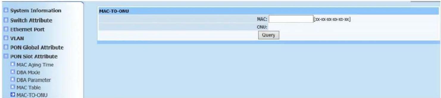
System Information Switch Attribute Ethernet Port VLAN PON Global Attribute PON Slot Attribute MAC Aging Time DBA Mode DBA Parameter MAC Table MAC-TO-ONU MAC: [xx-xx-xx-xx-xx-xx] ONU: QueryFigure7-5
This query page is used to find unknown information of OUN. Type MAC address to required ONU, click Search to display OUN location.
8. PON Port Attribute
8.1. Attribute
Web configuration page is shown as Figure (8-1):
text_image
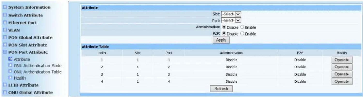
System Information Switch Attribute Ethernet Port VLAN PON Global Attribute PON Slot Attribute PON Port Attribute Attribute 1 2 3 4 Attribute Table Index Slot Port Administration P2P Modify 1 1 1 Disable Disable Operate 2 1 2 Disable Disable Operate 3 1 3 Disable Disable Operate 4 1 4 Disable Disable Operate RefreshFigure 8-1
This page is to configure PON port attribution, including management state and P2P configuration. Select modules and PON ports, configure management state to disable or enable and P2P to disable or enable (to configure all registered ONU under same PON port to intercommunication). Click Apply to automatically refresh the PON port attribution list after configuration is completed. Check if the displayed configuration information is as required.
8.2. ONU Authentication Mode
Web configuration page is shown as Figure (8-2):
text_image
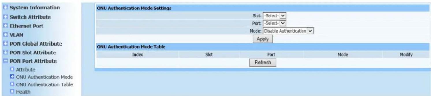
System Information Switch Attribute Ethernet Port VLAN PON Global Attribute PON Slot Attribute PON Port Attribute Attribute ONU Authentication Mode ONU Authentication Table Health ONU Authentication Mode Settings Slot: -Select-✓ Port: -Select-✓ Mode: Disable Authentication ✓ Apply ONU Authentication Mode Table Index Slot Port Mode Modify RefreshFigure 8-2
This page is to configure ONU authentication mode configuration, including Disable Authentication, MAC Authentication, LOID Authentication and Hybrid Authentication (mixed with MAC Authentication and LOID Authentication). Select modules and ports and then select corresponding authentication mode. Click Apply to automatically refresh the ONU authentication mode list after configuration is completed. Check if the displayed configuration information is as required.
8.3. ONU Authentication Table
Web configuration page is shown as Figure (8-3):
text_image
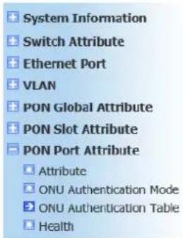
System Information Switch Attribute Ethernet Port VLAN PON Global Attribute PON Slot Attribute PON Port Attribute Attribute ONU Authentication Mode ONU Authentication Table Health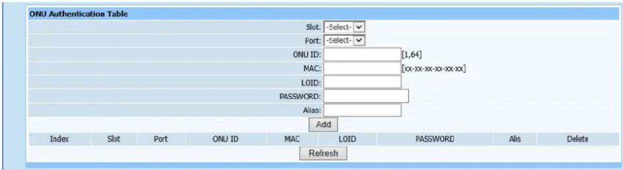
text_image
ONU Authentication Table Slot: -Select- Port: -Select- ONU ID: [1,64] MAC: [xx-xx-xx-xx-xx-xx] LOID: PASSWORD: Alias: Add Index Slot Port ONU ID MAC LOID PASSWORD Alis Delete RefreshFigure 8-3
This page is to add ONU authentication table and only ONU in the authentication table is allowed to register. Select modules and ports, type logic ONU ID and its MAC address, LOID, Password and Alias. Click Add to automatically refresh the ONU authentication table after configuration is completed. Check if the ONU has been added into list as required.
8.4. Health
Query page is shown as Figure (8-4):
text_image
System Information Switch Attribute Ethernet Port VLAN PON Global Attribute PON Slot Attribute PON Port Attribute Attribute ONU Authentication Mode ONU Authentication Table Health| Health Information | |||||||
| Index | Slot | Port | Temperature(℃) | Voltage(V) | Bias Current(mA) | Tx Power(uW) | Rx Power(uW) |
| 1 | 1 | 1 | 0.00 | 0.00 | 0.00 | 0.00 | 0.00 |
| 2 | 1 | 2 | 0.00 | 0.00 | 0.00 | 0.00 | 0.00 |
| 3 | 1 | 3 | 0.00 | 0.00 | 0.00 | 0.00 | 0.00 |
| 4 | 1 | 4 | 0.00 | 0.00 | 0.00 | 0.00 | 0.00 |
| Refresh | |||||||
Figure 8-4
This query page is used to find PON port environment diagnosis information.
9. LLID Attribute
9.1. MAC Limit
Web configuration page is shown as Figure (9-1):
text_image
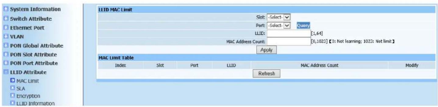
System Information Switch Attribute Ethernet Port VLAN PON Global Attribute PON Slot Attribute PON Port Attribute LLID Attribute MAC Limit SLA Encryption LLID Information LLID MAC Limit Slot: -Select- Port: -Select- Query LLID: [1,64] MAC Address Count: [0,1023] 【0: Not learning; 1023: Not limit】 Apply MAC Limit Table Index Slot Port LLID MAC Address Count Modify RefreshFigure 9-1
This page is to limit MAC of LLID port (grant maximum MAC address capacity table of ONU port). Select modules and ports, type required LLID number of ONU and MAC address capacity value. Click Apply to automatically refresh the LLID MAC limitation list after configuration is completed. Check if the displayed configuration information is as required.
9.2. SLA
Web configuration page is shown as Figure (9-2):
text_image
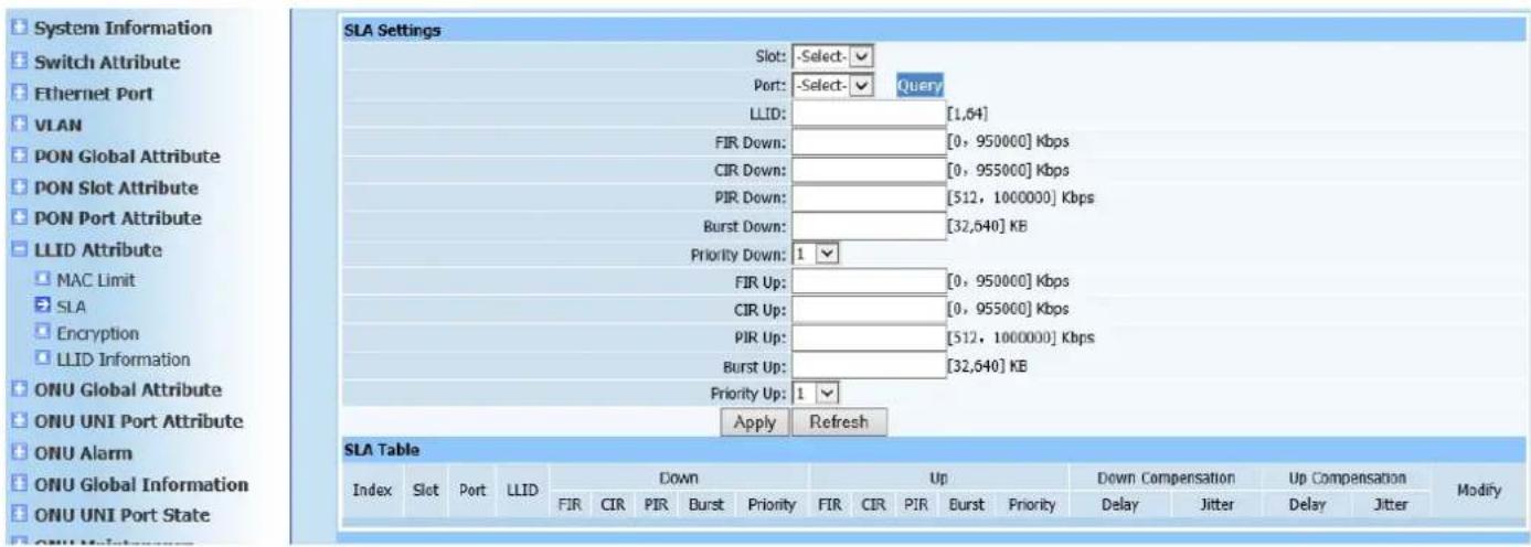
System Information Switch Attribute Ethernet Port VLAN PON Global Attribute PON Slot Attribute PON Port Attribute LLID Attribute MAC Limit SLA Encryption LLID Information ONU Global Attribute ONU UNI Port Attribute ONU Alarm ONU Global Information ONU UNI Port State SLA Settings Slot: -Select- ✓ Port: -Select- ✓ Query LLID: [1,64] FIR Down: [0, 950000] Kbps CIR Down: [0, 955000] Kbps PIR Down: [512, 1000000] Kbps Burst Down: [32,640] KB Priority Down: 1 ✓ FIR Up: [0, 950000] Kbps CIR Up: [0, 955000] Kbps PIR Up: [512, 1000000] Kbps Burst Up: [32,640] KB Priority Up: 1 ✓ Apply Refresh SLA Table Index Slot Port LLID Down Up Down Compensation Up Compensation Modify FIR CIR PIR Burst Priority FIR CIR PIR Burst Priority Delay Jitter Delay Jitter Delay ONU Global Information ONU UNI Port State ONU AlarmFigure 9-2
This page is to configure SLA parameter of ONU (DBA parameter configuration of ONU mainly refers to configure different types of band width). Select modules and ports, enter required LLID number of ONU and type SLA parameters. Click Apply to automatically refresh the LLID SLA parameter list after configuration is completed. Check if the displayed configuration information is as required.
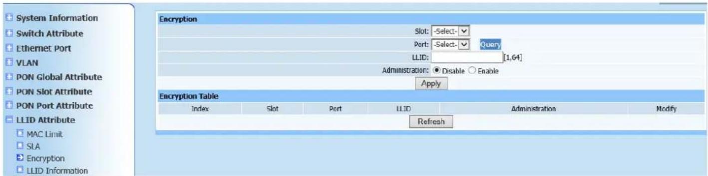
9.3. Encryption
Web configuration page is shown as Figure (9-3):
text_image
System Information Switch Attribute Ethernet Port VLAN PON Global Attribute PON Slot Attribute PON Port Attribute LLID Attribute MAC Limit SIA Encryption LLID Information Encryption Slot: -Select- Port: -Select- Query LLID: [1,64] Administration: ● Disable ○ Enable Apply Encryption Table Index Slot Port LLID Administration Modify RefreshFigure 9-3
This page is to configure ONU encryption Administration. Select modules and ports, enter required LLID number of ONU, and select encryption status (disable or enable). Click Apply to automatically refresh the LLID encryption enabling control list after configuration is completed. Check if the displayed
configuration information is as required.
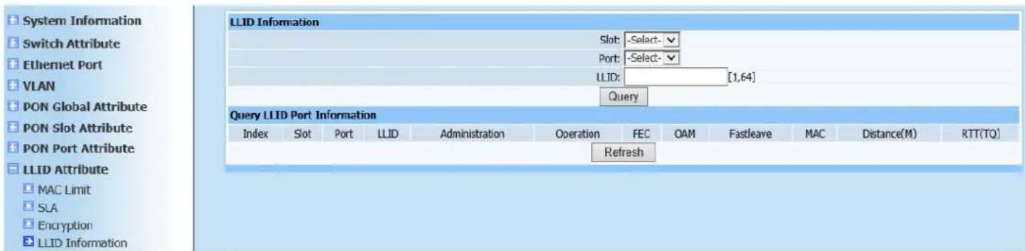
9.4. LLID Information
Query page is shown as Figure (9-4):
text_image
System Information Switch Attribute Ethernet Port VLAN PON Global Attribute PON Slot Attribute PON Port Attribute LLID Attribute MAC Limit SLA Encryption LLID Information LLID Information Slot: -Select- Port: -Select- LLID: [1,64] Query LLID Port Information Index Slot Port LLID Administration Operation FEC OAM Fastleave MAC Distance(M) RTT(TQ) RefreshFigure 9-4
This query page is used to find ONU information, including state management, port state, FEC state, OAM PUD limitation, Fastleave state, MAC address, LLID distance and LLID RTT distance.
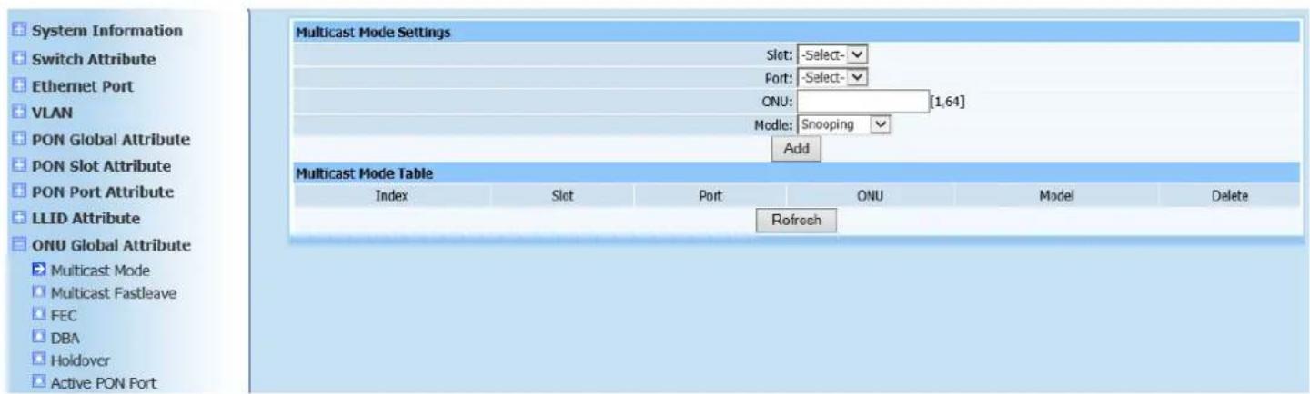
10. ONU Global Attribute
10.1. Multicast Mode
Web configuration page is shown as Figure (10-1):
text_image
System Information Switch Attribute Ethernet Port VLAN PON Global Attribute PON Slot Attribute PON Port Attribute LLID Attribute ONU Global Attribute Multicast Mode Multicast Fastleave FEC DBA Holdover Active PON Port Multicast Mode Settings Slot: -Select- Port: -Select- ONU: [1,64] Mode: Snooping Add Multicast Mode Table Index Slot Port ONU Model Delete RefreshFigure 10-1
This page is to configure ONU multicast mode. Multicast types fall into snooping and telecom-controllable. Click Apply to automatically refresh the ONU multicast mode list after configuration is completed. Check if the displayed configuration information is as required.
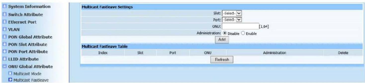
10.2. Multicast Fastleave
Web configuration page is shown as Figure (10-2):
text_image
System Information Switch Attribute Ethernet Port VLAN PON Global Attribute PON Slot Attribute PON Port Attribute LLID Attribute ONU Global Attribute Multicast Fastleave Settings Slot: -Select- Port: -Select- ONU: [1,64] Administration: ● Disable ○ Enable Add Multicast Fastleave Table Index Slot Port ONU Administration Delete RefreshFigure 10-2
This page is to configure multicast Fastleave management state of ONU. Select management state to disable or enable. Click Add to automatically refresh the ONU multicast Fastleave list after configuration is completed. Check if the ONU has been added into the table as required.
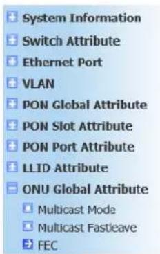
10.3. FEC
Web configuration page is shown as Figure (10-3):
text_image
System Information Switch Attribute Ethernet Port VLAN PON Global Attribute PON Slot Attribute PON Port Attribute LLID Attribute ONU Global Attribute Multicast Mode Multicast Fastleave FEC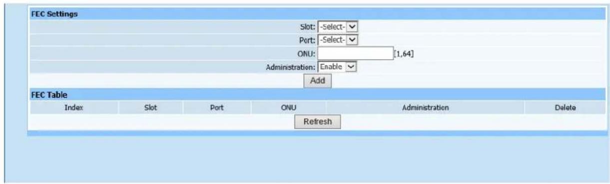
text_image
FEC Settings Slot: -Select- Port: -Select- ONU: [1,64] Administration: Enable Add FEC Table Index Slot Port ONU Administration Delete RefreshFigure 10-3
This page is to configure FEC capacity set of ONU. Select modules, ports, ONU logic ID and FEC capacity set (Unknown! Allowed! and Disable!). Click Add to automatically refresh the ONU FEC capacity list after configuration is completed. Check if the ONU FEC capacity set has been added into the table as required.
10.4. DBA
Web configuration page is shown as Figure (10-4):
text_image
DBA Settings Slot: -Select- Port: -Select- ONU: [1,6+] Query System Information Switch Attribute Ethernet Port VLAN PON Global Attribute PON Slot Attribute PON Port Attribute LLID Attribute ONU Global Attribute Multicast Mode Multicast Fastleave FEC DBAFigure 10-4
This page is to configure DBA of ONU. Select modules, ports, ONU logic ID and required queue number. Each queue has 8 mapping from from 0-7. Click Apply after configuration is completed. Prompt will pop up to show if it's
successfully configured.
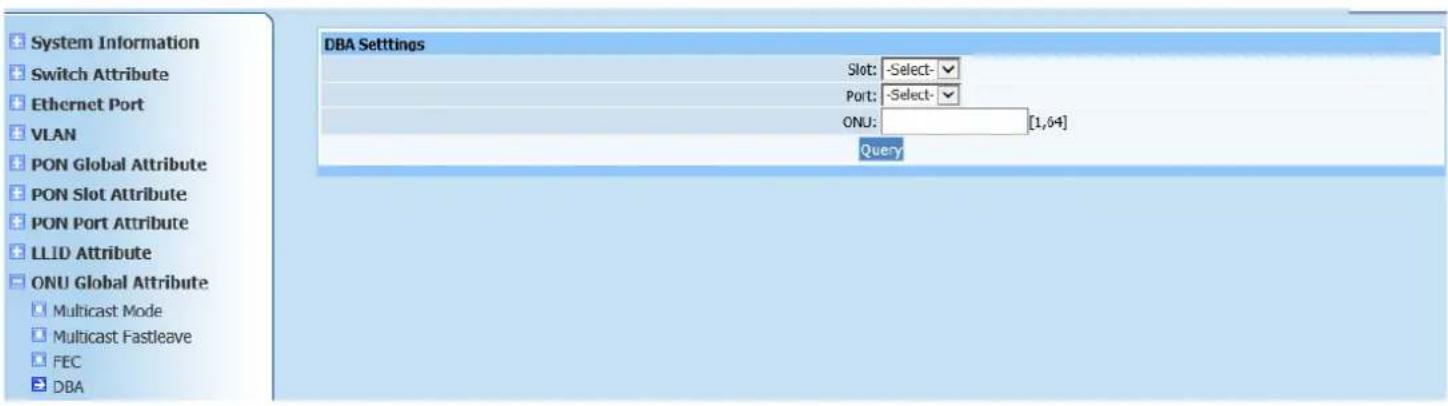
10.5. Holdover
Web configuration page is shown as Figure (10-5):
text_image
System Information Switch Attribute Ethernet Port VLAN PON Global Attribute PON Slot Attribute PON Port Attribute LLID Attribute ONU Global Attribute Multicast Mode Multicast Fastleave FEC DBA Holdover Holdover Settings Slot: -Select- Port: -Select- ONU: [1,64] Administration: Disable Enable Time: ms Apply Holdover Table Index Slot Port ONU Administration Time Delete RefreshFigure 10-5
This page is to configure holdover time of ONU. If Holdover status is enabled, ONU needs not to register again only if ONU can be connected within certain time range in case of abnormal outage.
Select modules, ports, ONU logic ID, holdover state and state hold time parameters. Click Apply to automatically refresh the ONU protection switching time list after configuration is completed. Check if the list information is as required.
10.6. Active PON Port
Web configuration page is shown as Figure (10-6):
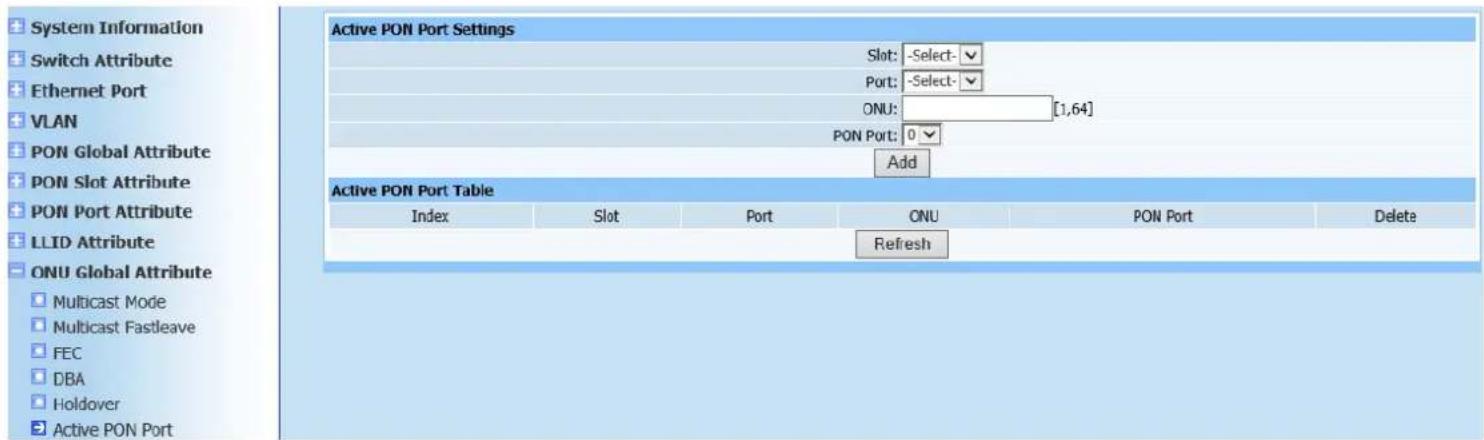
text_image
System Information Switch Attribute Ethernet Port VLAN PON Global Attribute PON Slot Attribute PON Port Attribute LLID Attribute ONU Global Attribute Multicast Mode Multicast Fastleave FEC DBA Holdover Active PON Port Active PON Port Settings Slot: -Select- Port: -Select- ONU: [1,64] PON Port: 0 Add Active PON Port Table Index Slot Port ONU PON Port Delete RefreshFigure 10-6
This page is to configure ONU Active port. Some ONUs have two PON ports, then Active port and backup port needs to configure when two PON ports are connected to OLT at the same time. If there is a failure to Active PON port, it will automatically switch to backup port. Select modules, ports, ONU logic ID and Active port parameters. Click Apply to automatically refresh the ONU Active port list after configuration is completed. Check if the required ONU Active port has been added.
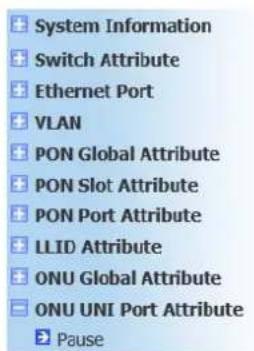
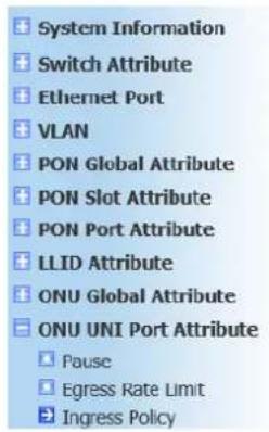
11. ONU UNI Port Attribute
11.1. Pause
Web configuration page is shown as Figure (11-1):
text_image
System Information Switch Attribute Ethernet Port VLAN PON Global Attribute PON Slot Attribute PON Port Attribute LLID Attribute ONU Global Attribute ONU UNI Port Attribute Pause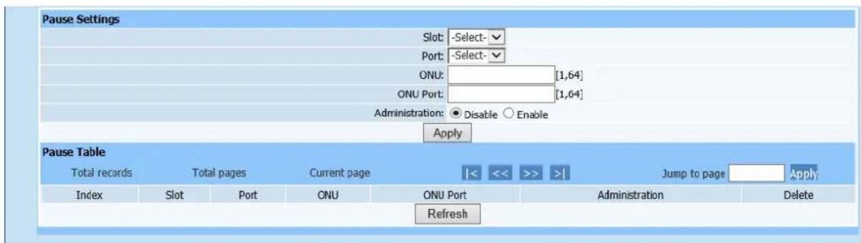
text_image
Pause Settings Slot: -Select- Port: -Select- ONU: [1,64] ONU Port: [1,64] Administration: ● Disable ○ Enable Apply Pause Table Total records Total pages Current page |<< >> >| Jump to page Apply Index Slot Port ONU ONU Port Administration Delete RefreshFigure 11-1
This page is to configure ONU UNI port Pause frame in order to play a role in flow control. If it exceeds limiting flow control, Pause frame will return.
Select modules, ports, ONU logic ID, ONU ports and configure flow control Administration to disable or enable. Click Apply to automatically refresh the Pause frame configuration list after configuration is completed. Check if the displayed configuration information is as required.
11.2. Egress Rate Limit
Web configuration page is shown as Figure (11-2):
text_image
System Information Switch Attribute Ethernet Port VLAN PON Global Attribute PON Slot Attribute PON Port Attribute LLID Attribute ONU Global Attribute ONU UNI Port Attribute Pause Egress Rate Limit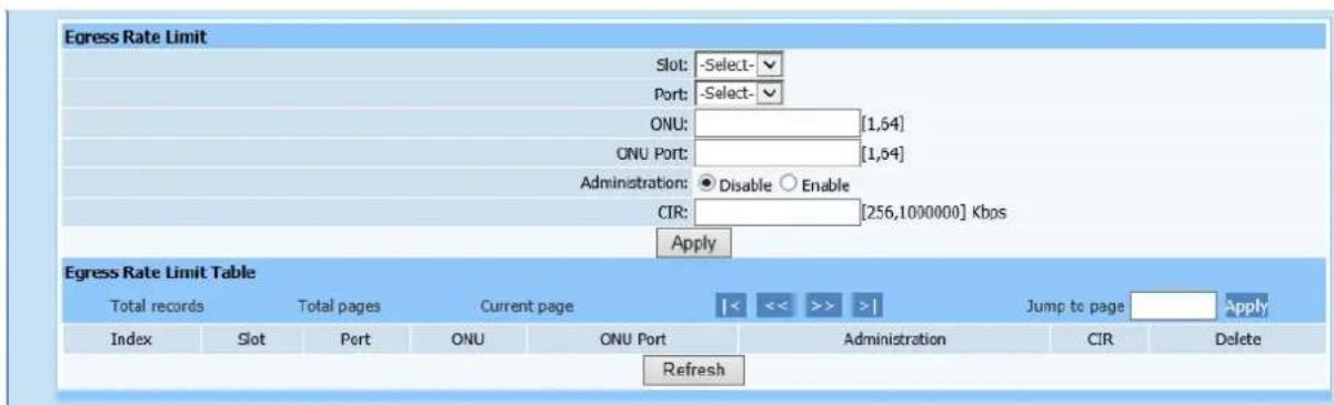
text_image
Egress Rate Limit Slot: -Select- Port: -Select- ONU: [1,64] ONU Port: [1,64] Administration: ● Disable ○ Enable CIR: [256,1000000] Kbps Apply Egress Rate Limit Table Total records Total pages Current page |<< >> >| Jump to page Apply Index Slot Port ONU ONU Port Administration CIR Delete RefreshFigure 11-2
This page is to configure ONU UNI port egress rate limit. Select required configuration parameter according to page prompting. Click Apply to automatically refresh the ONU UNI port egress rate limit table after configuration is completed. Check if the ONU UNI port upstream rate-limiting has been added.
11.3. Ingress Policy
Web configuration page is shown as Figure (11-3):
text_image
System Information Switch Attribute Ethernet Port VLAN PON Global Attribute PON Slot Attribute PON Port Attribute LLID Attribute ONU Global Attribute ONU UNI Port Attribute Pause Egress Rate Limit Ingress Policy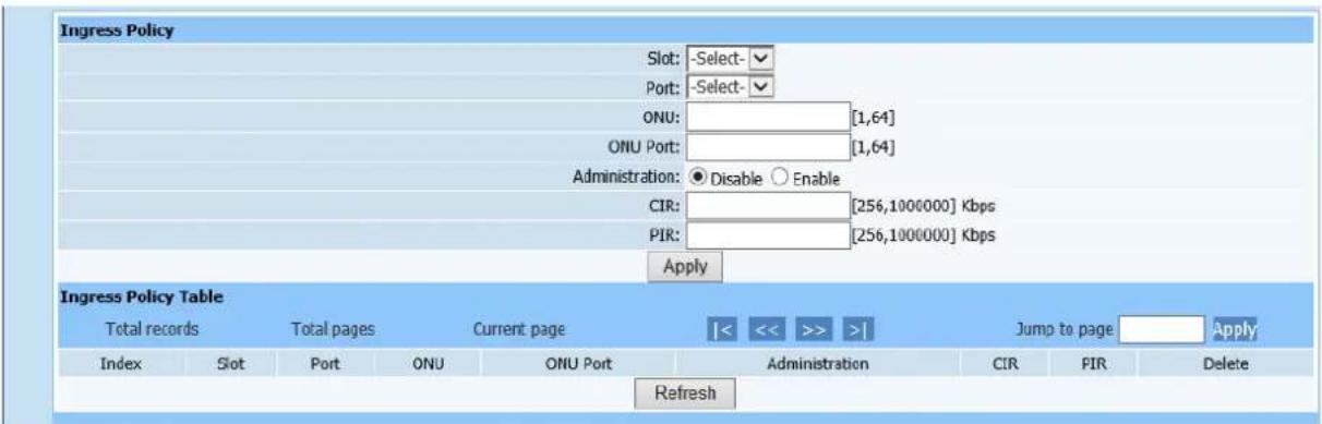
text_image
Ingress Policy Slot: -Select- Port: -Select- ONU: [1,64] ONU Port: [1,64] Administration: ● Disable ○ Enable CIR: [256,1000000] Kbps PIR: [256,1000000] Kbps Apply Ingress Policy Table Total records Total pages Current page Jump to page Apply Index Slot Port ONU ONU Port Administration CIR FIR Delete RefreshFigure11-3
This page is to configure ONU UNI port ingress rate limit. Select required configuration parameter according to page prompting. Click Apply to automatically refresh the ONU UNI port ingress rate limit table after configuration is completed. Check if the ONU UNI port downstream rate-limiting has been added.
11.4. VLAN
Web configuration page is shown as Figure (11-4):
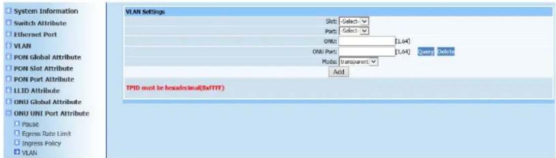
text_image
System Information Switch Attribute Ethernet Port VLAN PON Global Attribute PON Slot Attribute PON Port Attribute LLID Attribute ONU Global Attribute ONU UNI Port Attribute Pause Egress Rate Limit Ingress Policy VLAN VLAN Settings Slot: Select - Port: Select - ONU: [1,64] ONU Port: [1,64] Query Delete Mode: transparent Add TPID must be hexadecimal(0xFTTF)Figure 11-4
This page is to configure ONU UNI port VLAN. Select required configuration parameter according to page prompting. VLAN modes fall into transparent, tag, translation, N:1 aggregate and trunk. Select any mode rather than transparent, more configuration items will appear below. User needs to enter required parameters. Click Add after configuration is completed. A prompt will pop up to show if configuration has been successfully done on the page.
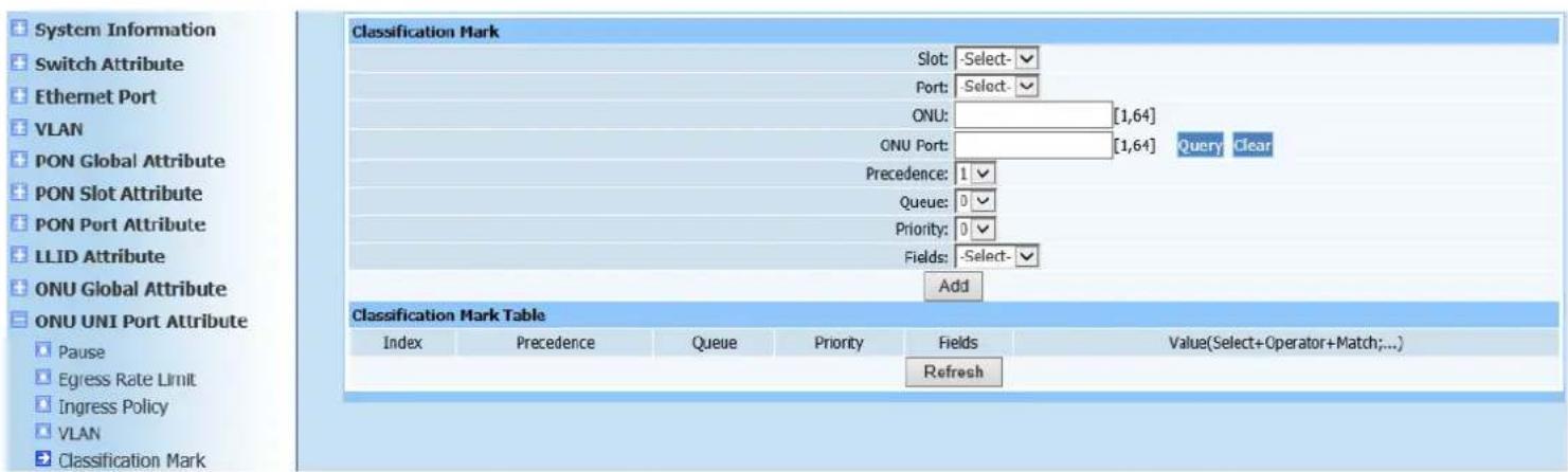
11.5. Classification Mark
Web configuration page is shown as Figure (11-5):
text_image
System Information Switch Attribute Ethernet Port VLAN PON Global Attribute PON Slot Attribute PON Port Attribute LLID Attribute ONU Global Attribute ONU UNI Port Attribute Pause Egress Rate Limit Ingress Policy VLAN Classification Mark Classification Mark Slot: -Select- Port: -Select- ONU: [1,64] ONU Port: [1,64] Query Clear Precedence: 1 Queue: 0 Priority: 0 Fields: -Select- Add Classification Mark Table Index Precedence Queue Priority Fields Value(Select+Operator+Match;...) RefreshFigure 11-5
This page is to configure ONU UNI port flow classification. Enter required configuration parameter according to page prompting. Notice that red font word should be corresponding the format of in item. Click Add to automatically refresh the flow classification configuration after configuration is completed.
Check if required configuration parameters has been added into list.
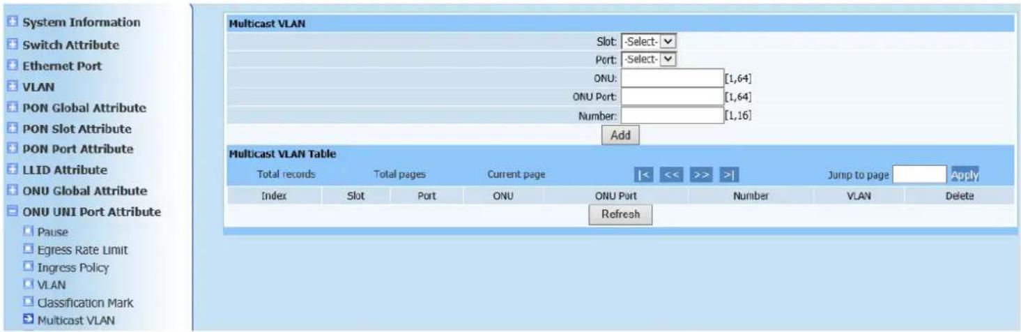
11.6. Multicast VLAN
Web configuration page is shown as Figure (11-6):
text_image
System Information Switch Attribute Ethernet Port VLAN PON Global Attribute PON Slot Attribute PON Port Attribute LLID Attribute ONU Global Attribute ONU UNI Port Attribute Pause Egress Rate Limit Ingress Policy VLAN Classification Mark Multicast VLAN Multicast VLAN Table Total records Total pages Current page << << >> >| Jump to page Apply Index Slot Port ONU ONU Port Number VLAN Delete RefreshFigure 11-6
This page is to configure ONU UNI port VLAN.
Instruction: Number of required VLAN for ONU port configuration is maximum number of multicast VLAN received at the port.
Click Add to automatically refresh the multicast VLAN list after configuration is completed. Check if required configuration has been added into list.
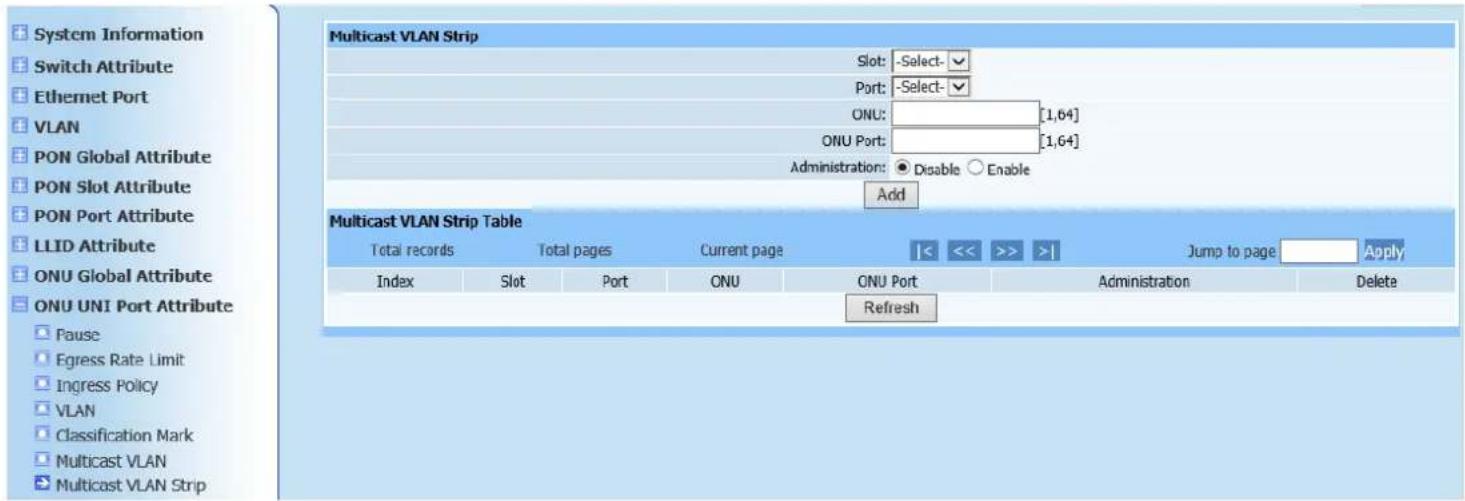
11.7. Multicast VLAN Strip
Web configuration page is shown as Figure (11-7):
text_image
System Information Switch Attribute Ethernet Port VLAN PON Global Attribute PON Slot Attribute PON Port Attribute LLID Attribute ONU Global Attribute ONU UNI Port Attribute Pause Egress Rate Limit Ingress Policy VLAN Classification Mark Multicast VLAN Multicast VLAN Strip Multicast VLAN Strip Table Total records Total pages Current page |<< >> | Jump to page Apply Index Slot Port ONU ONU Port Administration Delete RefreshFigure 11-7
This page is to clear ONU UNI port multicast VLAN. Select required configuration parameter according to page prompting. Click Add to automatically refresh the ONU UNI port multicast VLAN clearing after configuration is completed. Check if required parameters have been added into list.
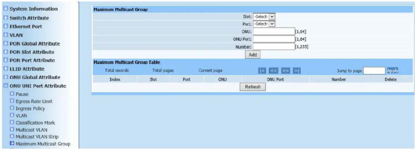
11.8. Maximum Multicast Group
Web configuration page is shown as Figure (11-8):
text_image
System Information Switch Attribute Ethernet Port VLAN PON Global Attribute PON Slot Attribute PON Port Attribute LLID Attribute ONU Global Attribute ONU UNI Port Attribute Pause Egress Rate Limit Ingress Policy VLAN Classification Mark Multicast VLAN Multicast VLAN Strip Maximum Multicast Group Slot: -Select-✓ Port: -Select-✓ ONU: [1,64] ONU Port: [1,64] Number: [1,255] Add Maximum Multicast Group Table Total records Total pages Current page Jump to page Apply Index Slot Port ONU ONU Port Number Delete RefreshFigure 11-8
This page is to configure ONU UNI port maximum multicast group, which is maximum multicast number supported by ONU ports. Configure parameters according to page prompting. Click Add to automatically refresh the maximum multicast group list after configuration is completed. Check if required configuration information has been added into list.
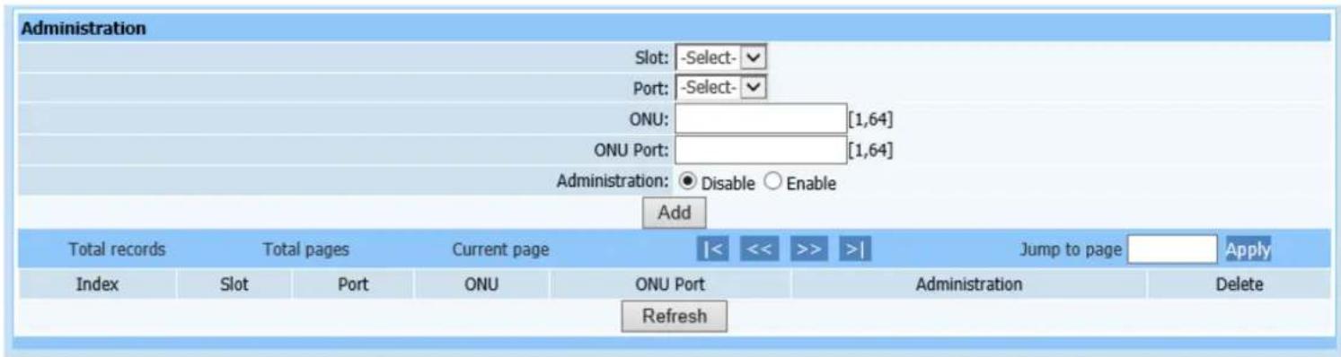
11.9. Administration
Web configuration page is shown as Figure (11-9):
text_image
Administration Slot: -Select- Port: -Select- ONU: [1,64] ONU Port: [1,64] Administration: ● Disable ○ Enable Add Total records Total pages Current page |< << >> >| Jump to page Apply Index Slot Port ONU ONU Port Administration Delete RefreshFigure 11-9
This page is to configure ONU UNI port Administration. Configure parameters according to page prompting. Select Administration status to disable or enable (disable means this ONU port is not available; enable means this ONU port under normal operation). Click Add to automatically refresh the PHY Administration list after configuration is completed. Check if required configuration information has been added into list.
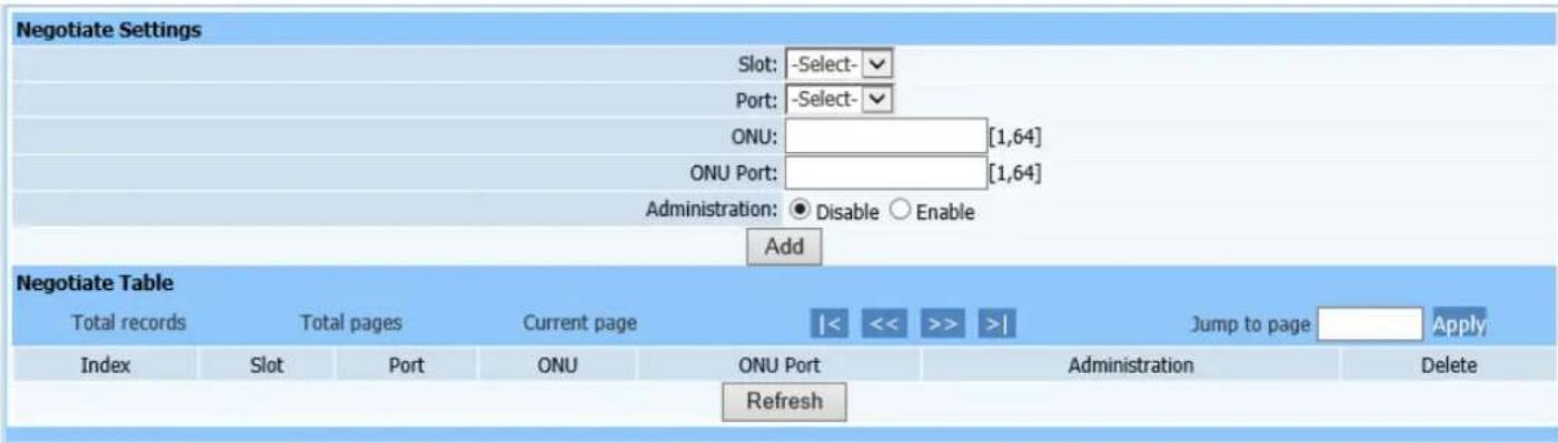
11.10. Negotiate
Web configuration page is shown as Figure (11-10):
text_image
Negotiate Settings Slot: -Select- Port: -Select- ONU: [1,64] ONU Port: [1,64] Administration: ● Disable ○ Enable Add Negotiate Table Total records Total pages Current page |< << >> >| Jump to page Apply Index Slot Port ONU ONU Port Administration Delete RefreshFigure 11-10
This page is to configure ONU UNI port automated negotiation. Configure parameters according to page prompting. Click Add to automatically refresh the automated negotiation list after configuration is completed. Check if required configuration information has been added into list.
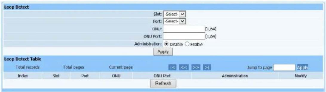
11.11. Loop Detect
Web configuration page is shown as Figure (11-11):
text_image
Loop Detect Slot: Select-✓ Port: -Select-✓ ONU: [1,64] ONU Port: [1,64] Administration: ● Disable ○ Enable Apply Loop Detect Table Total records Total pages Current page Jump to page Apply Index Slot Port ONU ONU Port Administration Modify RefreshFigure 11-11
This page is to detect UNI port loopback. Only select required modules, PON ports, ONU logic ID, ports, and loop detection administration status, then click Apply. Check if ONU UNI port loop detection has been added into following list.
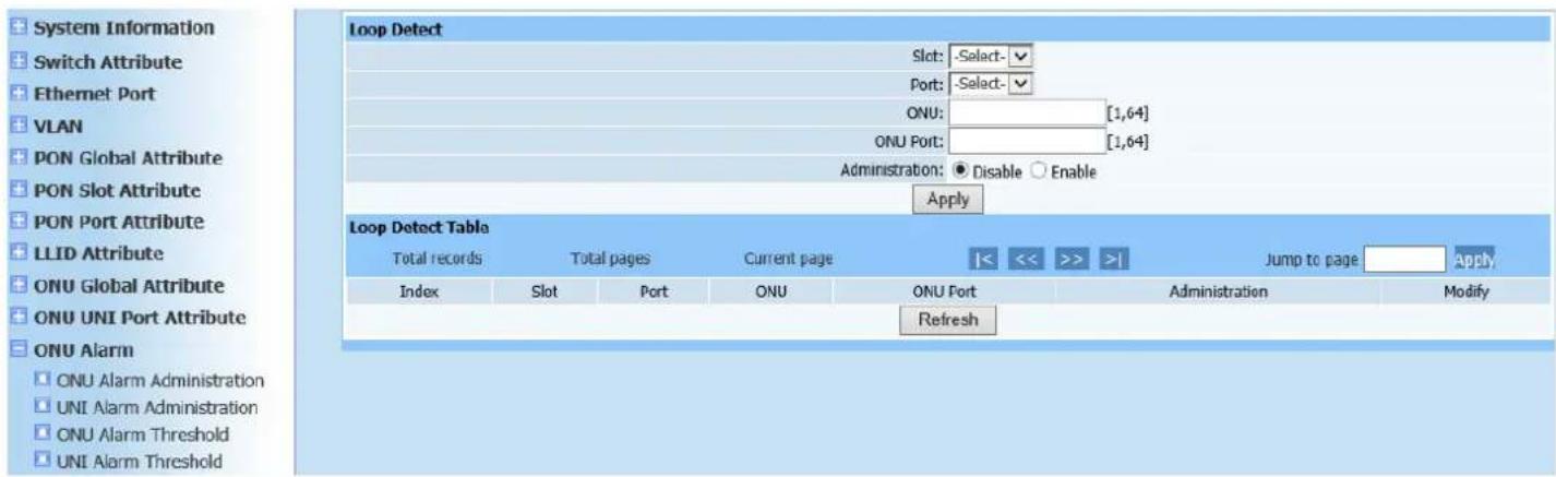
12. ONU Alarm
12.1. ONU Alarm Administration
Web configuration page is shown as Figure (12-1):
text_image
System Information Switch Attribute Ethernet Port VLAN PON Global Attribute PON Slot Attribute PON Port Attribute LLID Attribute ONU Global Attribute ONU UNI Port Attribute ONU Alarm ONU Alarm Administration UNI Alarm Administration ONU Alarm Threshold UNI Alarm Threshold Loop Detect Slot: -Select-✓ Port: -Select-✓ ONU: [1,64] ONU Port: [1,64] Administration: ● Disable ○ Enable Apply Loop Detect Table Total records Total pages Current page |<< >> >| Jump to page Apply Index Slot Port ONU ONU Port Administration Modify RefreshFigure 12-1
This page is to configure ONU Alarm Administration. Configure parameters according to page prompting. Click Add to automatically refresh the ONU Alarm Administration Table after configuration is completed. Check if required configuration information has been added into list.
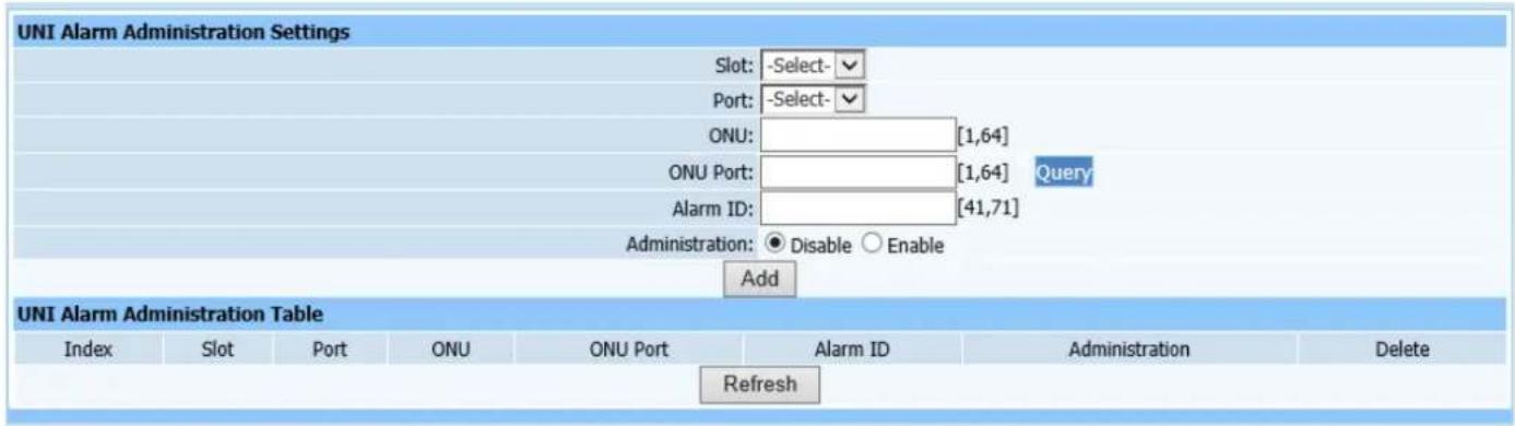
12.2. UNI Alarm Administration
Web configuration page is shown as Figure (12-2):
text_image
UNI Alarm Administration Settings Slot: -Select- Port: -Select- ONU: [1,64] ONU Port: [1,64] Query Alarm ID: [41,71] Administration: ● Disable ○ Enable Add UNI Alarm Administration Table Index Slot Port ONU ONU Port Alarm ID Administration Delete RefreshFigure 12-2
This page is to configure ONU UNI port Alarm. Configure parameters according to page prompting. Click Add to automatically refresh the ONU UNI port Alarm Administration Table after configuration is completed. Check if required configuration information has been added into list.
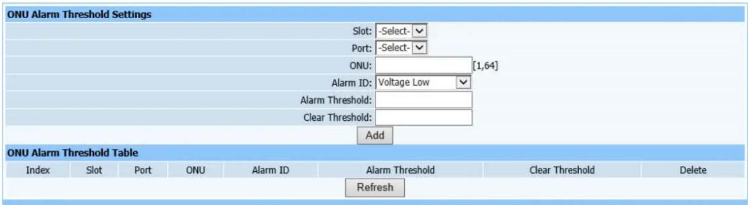
12.3. ONU Alarm Threshold
Web configuration page is shown as Figure (12-3):
text_image
ONU Alarm Threshold Settings Slot: -Select- Port: -Select- ONU: [1,64] Alarm ID: Voltage Low Alarm Threshold: Clear Threshold: Add ONU Alarm Threshold Table Index Slot Port ONU Alarm ID Alarm Threshold Clear Threshold Delete RefreshFigure 12-3
This page is to configure ONU alarm threshold. Configure alarm code first (i.e. Alarm mode, divided into brownout, high temperature and low temperature), and configure the threshold value of the required alarm mode. Click Add to automatically refresh the ONU UNI port alarm threshold list after configuration is completed. Check if required configuration information has been added into
list.
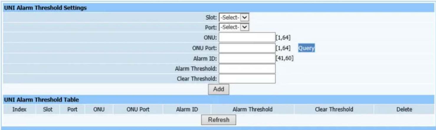
12.4. UNI Alarm Threshold
Web configuration page is shown as Figure (12-4):
text_image
UNI Alarm Threshold Settings Slot: -Select- Port: -Select- ONU: [1,64] ONU Port: [1,64] Query Alarm ID: [41,60] Alarm Threshold: Clear Threshold: Add UNI Alarm Threshold Table Index Slot Port ONU ONU Port Alarm ID Alarm Threshold Clear Threshold Delete RefreshFigure 12-4
This page is to configure ONU UNI port alarm threshold. Configuration instructions are the same format as ONU alarm threshold.
13. ONU Global Information
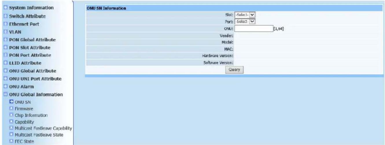
13.1. ONU SN
Query page is shown as Figure (13-1):
text_image
System Information Switch Attribute Ethernet Port VLAN PON Global Attribute PON Slot Attribute PON Port Attribute LLID Attribute ONU Global Attribute ONU UNI Port Attribute ONU Alarm ONU Global Information ONU SN Firmware Chip Information Capability Multicast Fastleave Capability Multicast Fastleave State FEC State ONU SN Information Slot: -Select- Port: -Select- ONU: [1,54] Vendor: Model: MAC: Hardware Version: Software Version: QueryFigure13-1
This page is to query ONU version information. Only select required modules and ports including ONU logic ID, and click Query.
13.2. Firmware
Query page is shown as Figure (13-2):
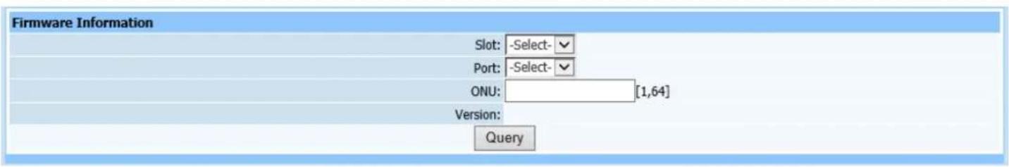
text_image
Firmware Information Slot: -Select- Port: -Select- ONU: [1,64] Version: QueryFigure 13-2
This query page is used to find ONU firmware information. Only select required modules and ports including ONU logic ID, and click Query.
13.3. Chip Information
Query page is shown as Figure (13-3):

text_image
Chip Information Slot: -Select- Port: -Select- ONU: [1,64] Vendor: Model: Version: Date: QueryFigure 13-3
This query page is used to find PON chip information. Only select required modules and ports including ONU logic ID, and click Query.
13.4. Capacity
Query page is shown as Figure (13-4):
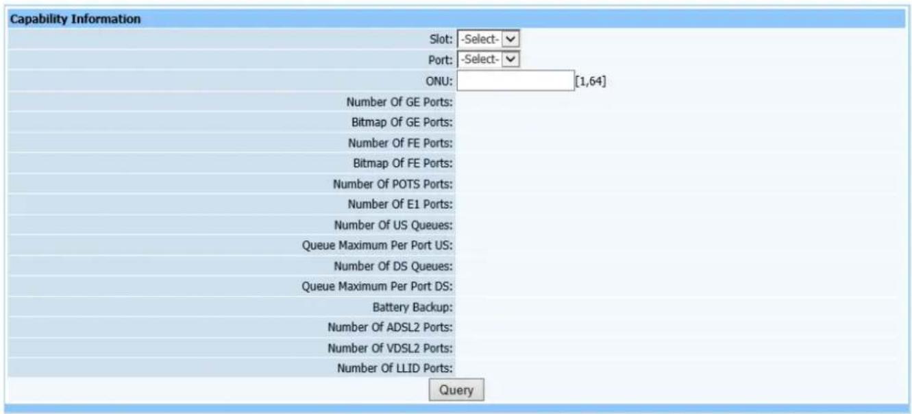
text_image
Capability Information Slot: -Select- Port: -Select- ONU: [1,64] Number Of GE Ports: Bitmap Of GE Ports: Number Of FE Ports: Bitmap Of FE Ports: Number Of POTS Ports: Number Of E1 Ports: Number Of US Queues: Queue Maximum Per Port US: Number Of DS Queues: Queue Maximum Per Port DS: Battery Backup: Number Of ADSL2 Ports: Number Of VDSL2 Ports: Number Of LLID Ports: QueryFigure 13-4
This query page is used to find PON capacity set. Only select required modules and ports including ONU logic ID, and click Query.
13.5. Multicast Fastleave Capacity
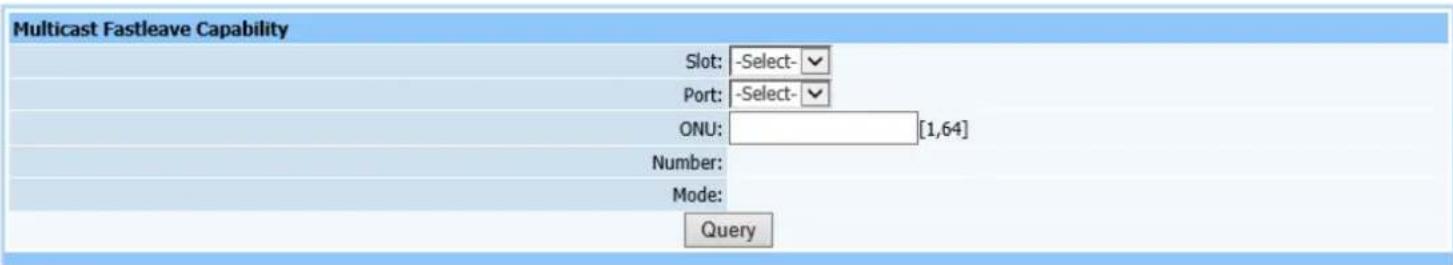
text_image
Multicast Fastleave Capability Slot: -Select- Port: -Select- ONU: [1,64] Number: Mode: QueryFigure 13-5
This query page is used to find multicast Fastleave capacity. Only select required modules and ports including ONU logic ID, and click Query.
13.6. Multicast Fastleave State
Query page is shown as Figure (13-6):
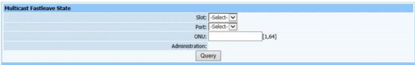
text_image
Multicast Fastleave State Slot: -Select- Port: -Select- ONU: [1,64] Administration: QueryFigure13-6
This query page is used to find multicast Fastleave state. Only select required modules and ports including ONU logic ID, and click Query.
13.7. FEC State
Query page is shown as Figure (13-7):

text_image
FEC State Information Slot: -Select- Port: -Select- ONU: [1,64] State: QueryFigure13-7
This query page is used to find FEC state. Only select required modules and ports including ONU logic ID, and click Query.
14. ONU UNI Port State
14.1. Link State
Query page is shown as Figure (14-1):
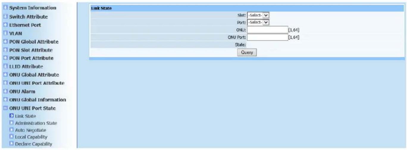
text_image
System Information Switch Attribute Ethernet Port VLAN PON Global Attribute PON Slot Attribute PON Port Attribute LLID Attribute ONU Global Attribute ONU UNI Port Attribute ONU Alarm ONU Global Information ONU UNI Port State Link State Administration State Auto Negotiate Local Capability Declare Capability Link State Slot: -Select- Port: -Select- ONU: [1,64] ONU Port: [1,64] State: QueryFigure 14-1
This query page is used to find ONU UNI port link status information. Only select required modules and ports including ONU logic ID and port, and click Query.
14.2. Administration State
Query page is shown as Figure (14-2):

text_image
Administration State Information Slot: -Select- Port: -Select- ONU: [1,64] ONU Port: [1,64] State: QueryFigure 14-2
This query page is used to find ONU UNI port administration state. Only select required modules and ports including ONU logic ID and port, and click Query.
14.3. Auto Negotiation
Query page is shown as Figure (14-3):

text_image
Auto Negotiate Slot: -Select- Port: -Select- ONU: [1,64] ONU Port: [1,64] State: QueryFigure 14-3
This query page is used to find ONU UNI port UNI auto negotiation information.
Only select required modules and ports including ONU logic ID and port, and click Query.
14.4. Local Capability
Query page is shown as Figure (14-4):
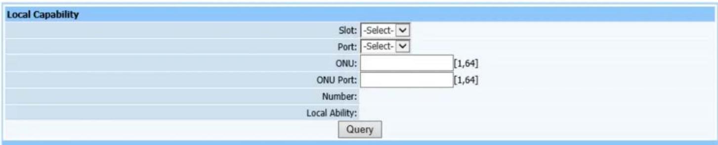
text_image
Local Capability Slot: -Select- Port: -Select- ONU: [1,64] ONU Port: [1,64] Number: Local Ability: QueryFigure 14-4
This query page is used to find ONU UNI port UNI local capability information.
Only select required modules and ports including ONU logic ID and port, and click Query.
14.5. Declare Capability
Query page is shown as Figure (14-5):
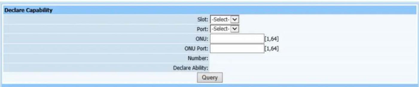
text_image
Declare Capability Slot: -Select- Port: -Select- ONU: [1,64] ONU Port: [1,64] Number: Declare Ability: QueryFigure 14-5
This query page is used to find ONU UNI port declare capability. Only select required modules and ports including ONU logic ID and port, and click Query.
15. ONU Maintenance
15.1. Reset ONU
Web configuration page is shown as Figure (15-1):
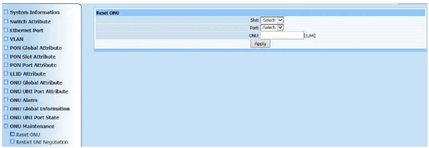
text_image
System Information Switch Attribute Ethernet Port VLAN PON Global Attribute PON Slot Attribute PON Port Attribute LLID Attribute ONU Global Attribute ONU UNI Port Attribute ONU Alarm ONU Global Information ONU UNI Port State ONU Maintenance Reset ONU Restart UNI Negotiation Reset ONU Slot: Select - Port: Select - CNU: [1,64] ApplyFigure 15-1
This page is to reset ONU. Only select required modules, PON ports and ONU logic ID, then click Apply.
15.2. Restart UNI Negotiation
Web configuration page is shown as Figure (15-2):

text_image
Restart UNI Negotiation Slot: -Select- Port: -Select- ONU: [1,64] ONU Port: [1,64] ApplyFigure 15-2
This page is to restart UNI auto negotiation. Only select required modules, PON ports and ONU logic ID, then click Apply.
16. Multicast
16.1. Multicast Parameter Settings
Web configuration page is shown as Figure (16-1):
text_image
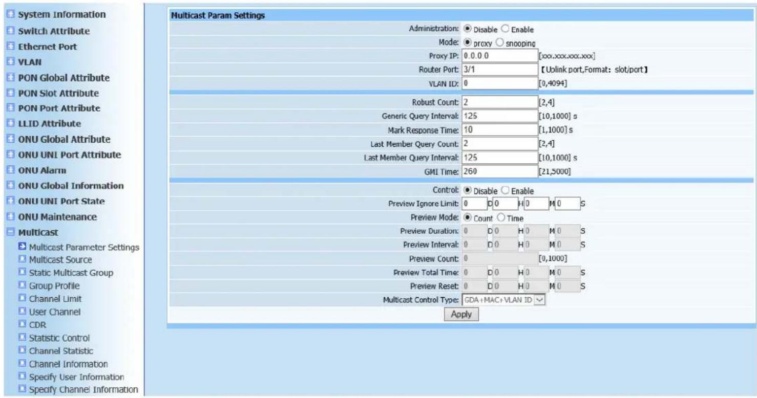
System Information Switch Attribute Ethernet Port VLAN PON Global Attribute PON Slot Attribute PON Port Attribute LLID Attribute ONU Global Attribute ONU UNI Port Attribute ONU Alarm ONU Global Information ONU UNI Port State ONU Maintenance Multicast Multicast Parameter Settings Multicast Source Static Multicast Group Group Profile Channel Limit User Channel CDR Statistic Control Channel Statistic Channel Information Specify User Information Specify Channel Information Multicast Param Settings Administration: Disable Enable Mode: proxy snooping Proxy IP: 0.0.0 [xxx.xxx.xxx.xxx] Router Port: 3/1 【Uplink port,Format: slot/port】 VLAN ID: 0 [0,4094] Robust Count: 2 [2,4] Generic Query Interval: 125 [10,1000] s Mark Response Time: 10 [1,1000] s Last Member Query Count: 2 [2,4] Last Member Query Interval: 125 [10,1000] s GMI Time: 260 [21,5000] Control: Disable Enable Preview Ignore Limit: 0 D 0 H 0 M 0 S Preview Mode: Count Time Preview Duration: 0 D 0 H 0 M 0 S Preview Interval: 0 D 0 H 0 M 0 S Preview Count: 0 [0,1000] Preview Total Time: 0 D 0 H 0 M 0 S Preview Reset: 0 D 0 H 0 M 0 S Multicast Control Type: GDA+MAC+VLAN ID ApplyFigure 16-1
This page is to configure multicast parameters. Configure required parameters according to page prompting. The gray part can only be configured when controlled multicast enabling status is selected to enable. Click Apply after configuration is completed. Prompt will pop up to show if it's successfully configured.
16.2. Multicast Source
Web configuration page is shown as Figure (16-2):
text_image
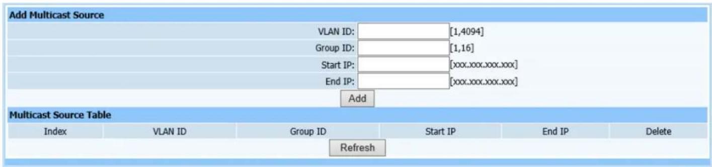
Add Multicast Source VLAN ID: [1,4094] Group ID: [1,16] Start IP: [xxx.xxx.xxx.xxx] End IP: [xxx.xxx.xxx.xxx] Add Multicast Source Table Index VLAN ID Group ID Start IP End IP Delete RefreshFigure 16-2
This page is to add multicast source. Configure required parameters according to page prompting. One thing to note is that starting IP and cut-of IP are all multicast IP which has strict definition. Click Add to automatically refresh the multicast source list after configuration is completed. Check if the configured parameters have been added into list.
16.3. Static Multicast Group
Web configuration page is shown as Figure (16-3):
text_image
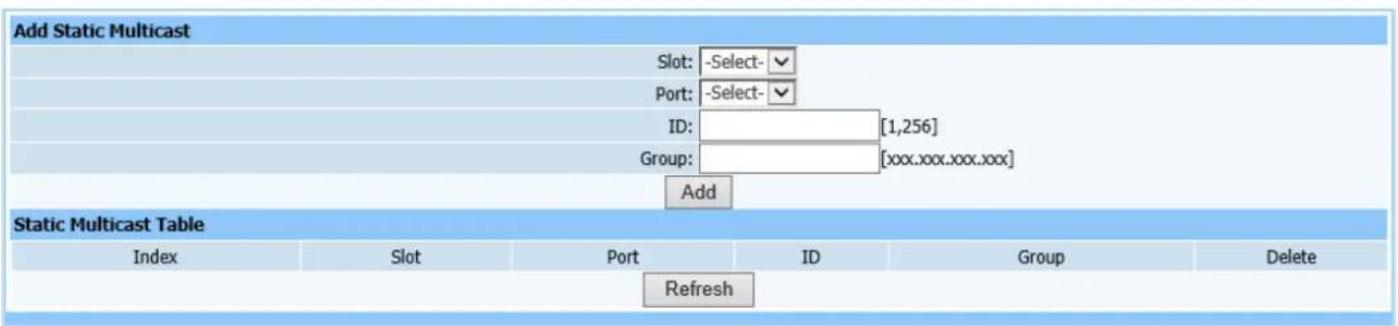
Add Static Multicast Slot: -Select- Port: -Select- ID: [1,256] Group: [xxx.xxx.xxx.xxx] Add Static Multicast Table Index Slot Port ID Group Delete RefreshFigure 16-3
This page is to configure static multicast group. Select modules, ports and indexes numbered as static multicast group, then enter multicast source ip. Click Add to automatically refresh the static multicast group after configuration is completed. Check if the configured parameters have been added into list.
16.4. Group Profile
Web configuration page is shown as Figure (16-4):
text_image
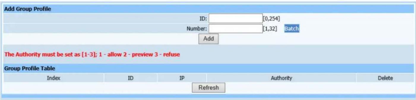
Add Group Profile ID: [0,254] Number: [1,32] Batch Add The Authority must be set as [1-3]; 1 - allow 2 - preview 3 - refuse Group Profile Table Index ID IP Authority Delete RefreshFigure 16-4
This page is to configure multicast group profile. Tips: Every multicast IP has three type permission: 1 represents allow, 2 represents preview and 3 represents decline. Click Add to automatically refresh the multicast permission template list after configuration is completed. Check if the configured parameters have been added into list.
16.5. Channel Limit and User Channel
Web configuration page is shown as Figure (16-5) and (16-6):
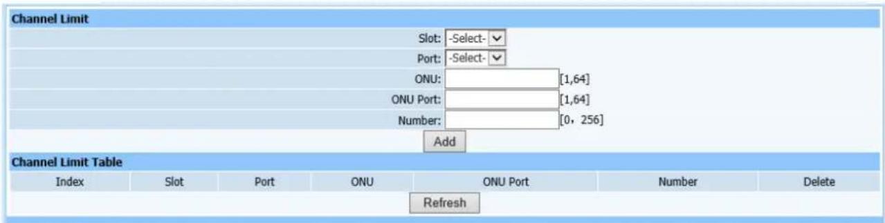
text_image
Channel Limit Slot: -Select- Port: -Select- ONU: [1,64] ONU Port: [1,64] Number: [0, 256] Add Channel Limit Table Index Slot Port ONU ONU Port Number Delete RefreshFigure 16-5

text_image
User Channel Slot: -Select- Port: -Select- ONU: [1,64] ONU Port: [1,64] ID: [1, 8] Query Mode: Bind Mode Profile ID: AddFigure 16-6
This page is to configure multicast channel limit and user multicast channel. Configure required parameters according to page prompting. Tips: Index is the value of multicast permission template. Click Add after configuration is completed. Window prompt will pop up to show if it's successfully configured on the page.
16.6. CDR
Web configuration page is shown as Figure (16-6):
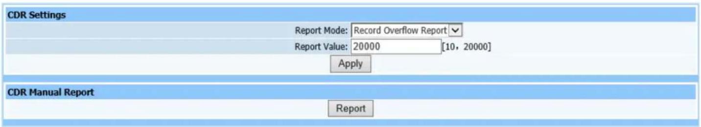
text_image
CDR Settings Report Mode: Record Overflow Report Report Value: 20000 [10, 20000] Apply CDR Manual Report ReportFigure 16-6
This page is to configure multicast CDR control parameters. CDR refers to report. Configure report mode and overflow parameters of CDR according page prompting. Click Apply after configuration is completed. Window prompt will pop up to show if it's successfully configured on the page.
16.7. Statistic Control
Web configuration page is shown as Figure (16-7):
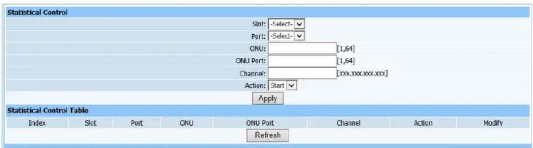
text_image
Statistical Control Slot: -Select- Port: -Select- ONU: [1,64] ONU Port: [1,64] Channel: [xxx.xxx.xxx.xxx] Action: Start Apply Statistical Control Table Index Slot Port ONU ONU Port Channel Action Modify RefreshFigure 16-7
This page is to configure multicast statistic control parameters for ONU port. Click Apply after configuration is completed. Window prompt will pop up to show if it's successfully configured on the page.
16.8. Channel Statistic
Web configuration page is shown as Figure (16-8):
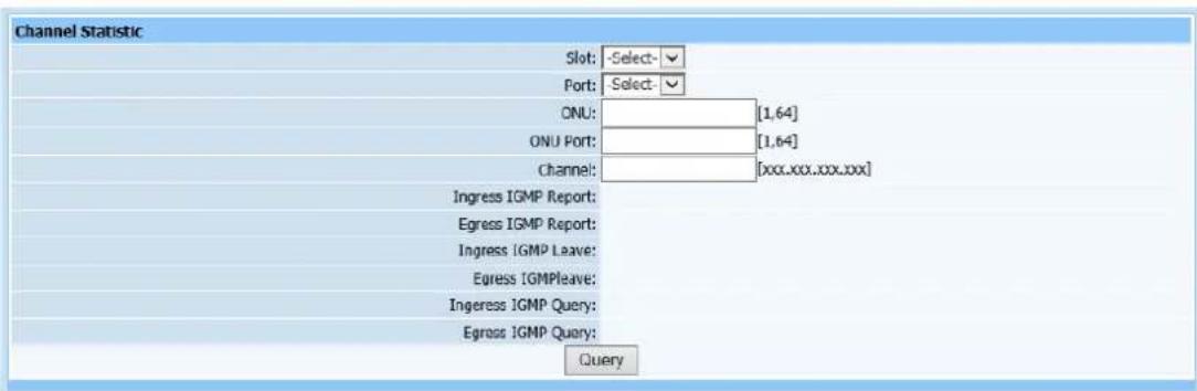
text_image
Channel Statistic Slot: -Select- Port: Select- ONU: [1,64] ONU Port: [1,64] Channel: [xxx.xxx.xxx.xx] Ingress IGMP Report: Egress IGMP Report: Ingress IGMP Leave: Egress IGMPleave: Ingress IGMP Query: Egress IGMP Query: QueryFigure 16-8
This page is to check multicast channel statistic. Only select required modules and ports including ONU logic ID, port and Channel, and click Query.
16.9. Channel Information
Query page is shown as Figure (16-9):

text_image
Channel Information Total records Total pages Current page |<< >> >1 Jump to page Apply Index Slot Port ONU ID ONU Port IP RefreshFigure 16-9
This query page is used to find all user channel information. Only switch to this page, all user channel information will display in the list on this page.
16.10. Specify User Information
Query page is shown as Figure (16-10):

text_image
Specify User Information Slot: -Select- Port: -Select- ONU: [1,64] ONU Port: [1,64] IP QueryFigure 16-10
This query page is used to find specific user channel information. Switch to this page, select modules, ports, OUN logic ID and ONU ports, multicast ip address of specific user channel information will display.
16.11. Specify Channel Information
Query page is shown as Figure (16-11):
text_image
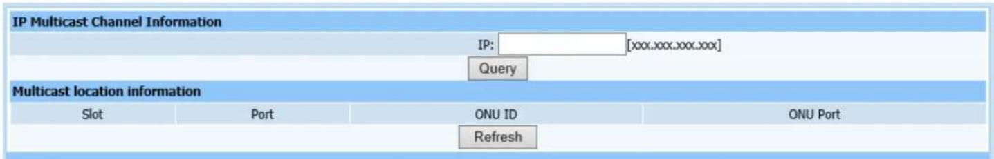
IP Multicast Channel Information IP: ________[xxx.xxx.xxx.xxx] Query Multicast location information Slot Port ONU ID ONU Port RefreshFigure 16-11
This query page is used to find user information of specific channel. Enter multicast IP address, then click Refresh to display all user information of the channel.
17. STP
17.1. STP Bridge Settings
Web configuration page is shown as Figure (17-1):
text_image
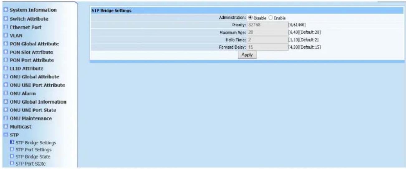
System Information Switch Attribute Ethernet Port VLAN PON Global Attribute PON Slot Attribute PON Port Attribute LLID Attribute ONU Global Attribute ONU UNI Port Attribute ONU Alarm ONU Global Information ONU UNI Port State ONU Maintenance Multicast STP STP Bridge Settings STP Port Settings STP Bridge State STP Port State STP Bridge Settings Administration: Disable Enable Priority: 32768 [0,61440] Maximum Age: 20 [6,40][Default:20] Hello Time: 2 [1,10][Default:2] Forward Delay: 15 [4,30][Default:15] ApplyFigure 17-1
This page is to configure bridge of STP. Main parameters required to configure are spanning administration, priority, aging time, hello time and forward delay time. Click Apply after configuration is completed. Window prompt will pop up to show if it's successfully configured on the page.
17.2. STP Port Settings
Web configuration page is shown as Figure (17-2):
text_image
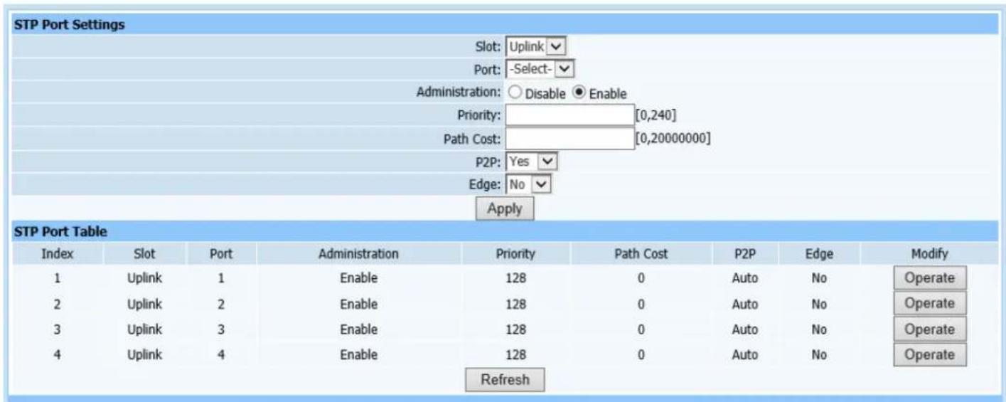
STP Port Settings Slot: Uplink Port: -Select- Administration: ○ Disable ● Enable Priority: [0,240] Path Cost: [0,20000000] P2P: Yes Edge: No Apply STP Port Table Index Slot Port Administration Priority Path Cost P2P Edge Modify 1 Uplink 1 Enable 128 0 Auto No Operate 2 Uplink 2 Enable 128 0 Auto No Operate 3 Uplink 3 Enable 128 0 Auto No Operate 4 Uplink 4 Enable 128 0 Auto No Operate RefreshFigure 17-2
This page is to configure ports of STP. Configure required parameters according to page prompting as shown in Figure 17-2. Click Apply to automatically refresh the spanning tree port configuration list after configuration is completed. Check if the required parameters have been added into list..
17.3. STP Bridge State
Query page is shown as Figure (17-3):
| STP Bridge State | |
| MAC: 00-00-00-00-00-00 | |
| Priority: 32768 | |
| Root MAC: 00-00-00-00-00-00 | |
| Root Port: 0 | |
| Root Path Cost: 0 | |
| Root Maximum Age: 0 | |
| Root Hello Time: 0 | |
| Root Forward Delay: 0 | |
Figure 17-3
This query page is used to find configured parameters above to see if they are required parameters. Only switch to this page to query required information.
17.4. STP Port State
Web configuration page is shown as Figure (17-4):
text_image
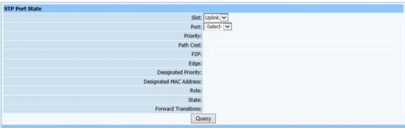
STP Port State Slot: Uplink Port: -Select- Priority: Path Cost: P2P: Edge: Designated Priority: Designated MAC Address: Role: State: Forward Transitions: QueryFigure 17-4
This query page is used to find port state of STP. Only select modules and ports, then click Query to find required information.
18. DHCP
18.1. Option82
Web configuration page is shown as Figure (18-1):
text_image
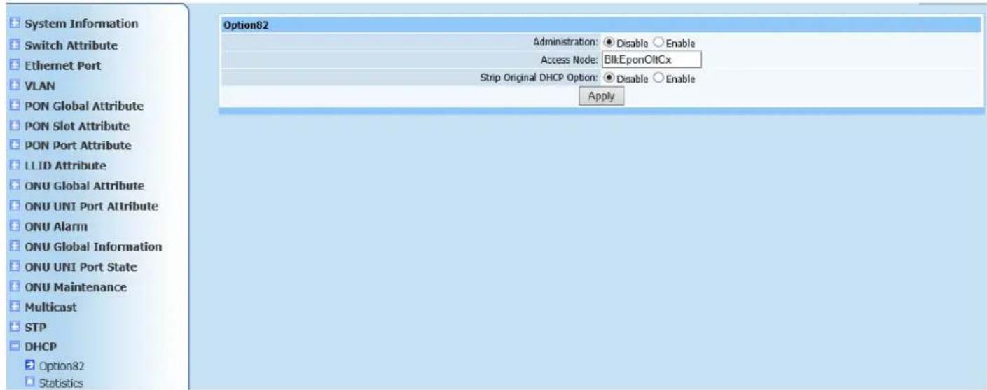
System Information Switch Attribute Ethernet Port VLAN PON Global Attribute PON Slot Attribute PON Port Attribute LLID Attribute ONU Global Attribute ONU UNI Port Attribute ONU Alarm ONU Global Information ONU UNI Port State ONU Maintenance Multicast STP DHCP Option82 Statistics Option82 Administration: Disable Enable Access Node: EikEponOltCx Strip Original DHCP Option: Disable Enable ApplyFigure 18-1
This page is to configure DHCP. Configure required parameters according to page prompting as shown in Figure 18-1. Click Apply after configuration is completed. Window prompt will pop up to show if it's successfully configured on the page.
18.2. Statistics
Query page is shown as Figure (18-2):
text_image
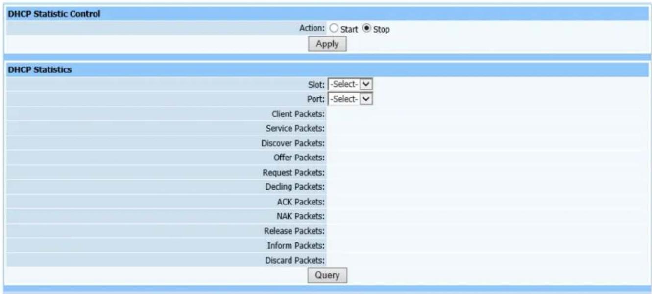
DHCP Statistic Control Action: ○ Start ● Stop Apply DHCP Statistics Slot: -Select- Port: -Select- Client Packets: Service Packets: Discover Packets: Offer Packets: Request Packets: Decling Packets: ACK Packets: NAK Packets: Release Packets: Inform Packets: Discard Packets: QueryFigure 18-2
This query page is used to find DHCP information. Configure DHCP message statistic control to starting statistical mode first, select modules and ports, then click Query to find required information.
19. PPPoE
19.1. PPPoE+
Web configuration page is shown as Figure (19-1):
text_image
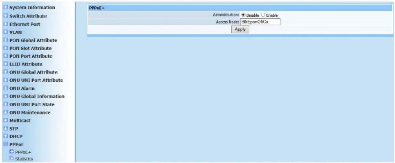
System Information Switch Attribute Ethernet Port VLAN PON Global Attribute PON Slot Attribute PON Port Attribute LLID Attribute ONU Global Attribute ONU UNI Port Attribute ONU Alarm ONU Global Information ONU UNI Port State ONU Maintenance Multicast STP DHCP PPPoE PPPoE+ Statistics PPPoE+ Administration: Disable Enable Access Node: BlkEponOltCx ApplyFigure 19-1
This page is to configure PPPoE. Configure according to prompt as shown in Figure 19-1.
19.2. Statistics
Query page is shown as Figure (19-2):
text_image
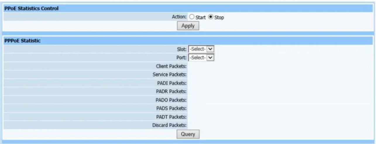
PPoE Statistics Control Action: ○ Start ● Stop Apply PPPoE Statistic Slot: -Select- Port: -Select- Client Packets: Service Packets: PADI Packets: PADR Packets: PADO Packets: PADS Packets: PADT Packets: Discard Packets: QueryFigure 19-2
This query page is used to find PPPoE message statistics.
20. Alarm
20.1. Alarm Redefine
Web configuration page is shown as Figure (20-1):
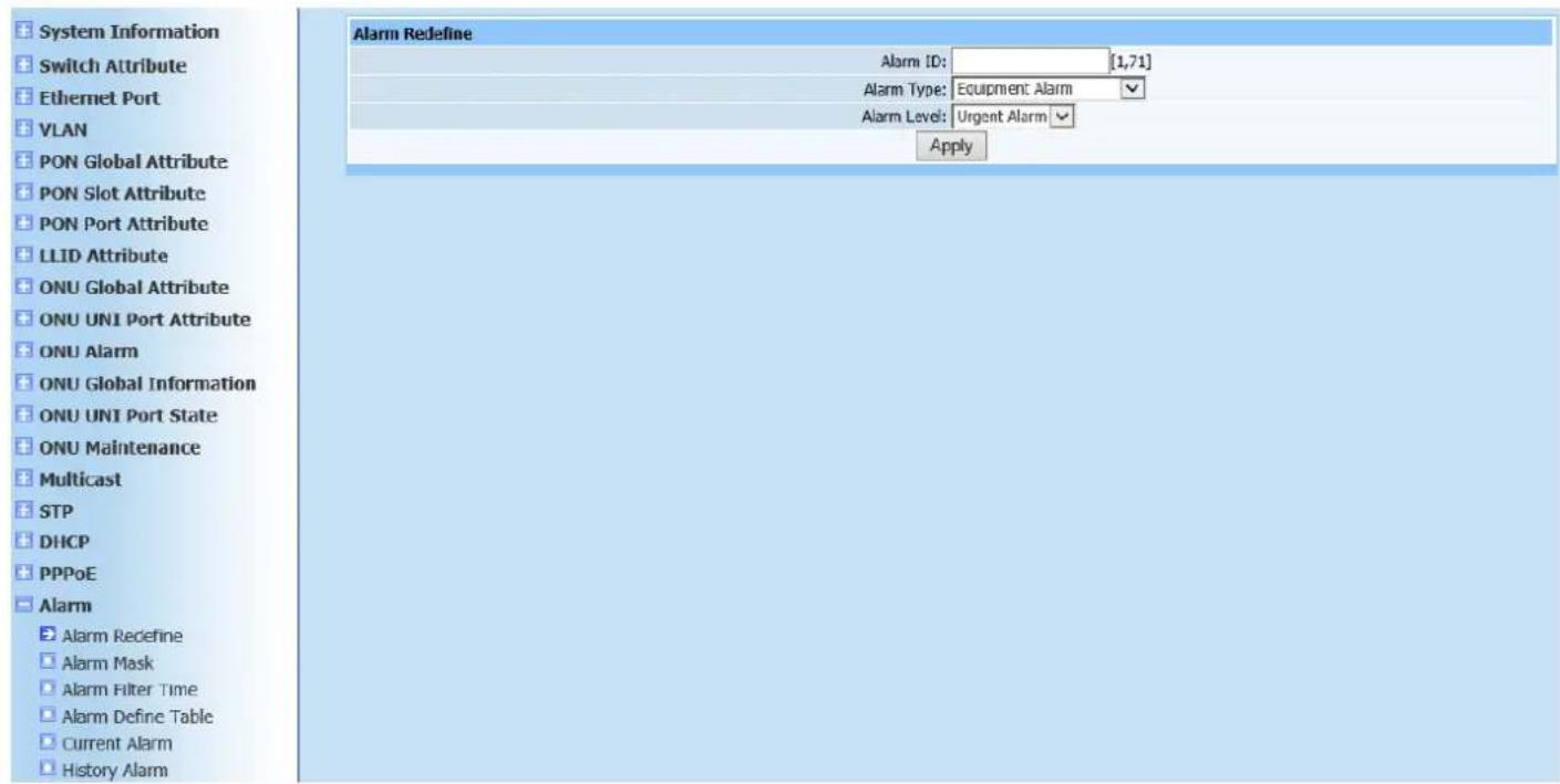
text_image
System Information Switch Attribute Ethernet Port VLAN PON Global Attribute PON Slot Attribute PON Port Attribute LLID Attribute ONU Global Attribute ONU UNI Port Attribute ONU Alarm ONU Global Information ONU UNI Port State ONU Maintenance Multicast STP DHCP PPPoE Alarm Alarm Redefine Alarm Mask Alarm Filter Time Alarm Define Table Current Alarm History Alarm Alarm Redefine Alarm ID: [1,71] Alarm Type: Equipment Alarm Alarm Level: Urgent Alarm ApplyFigure 20-1
This page is to configure alarm redefinition. Configure alarm ID parameters, alarm types (1 Equipment Alarm, 2 Service Alarm, 3 Communication Alarm, 4 Environment Alarm and 5 Processing Failed Alarm) and alarm (1 Urgent Alarm, 2 Major Alarm, 3 Minor Alarm and 4 Warning). Click Apply after configuration is completed. A serial interface window will appear if configuration was completed successfully.
20.2. Alarm Mask
Query page is shown as Figure (20-2):

text_image
Alarm Mask Administration: ○ Disable ● Enable ApplyFigure 20-2
This page is to configure alarm block Administration.
20.3. Alarm Filtering Time
Web configuration page is shown as Figure (20-3):

text_image
Alarm Filter Time Time: 5 [1,10] s ApplyFigure 20-3
This page is to configure alarm filtering time.
20.4. Alarm Definition Table
Query page is shown as Figure (20-4):
| Alarm Define Table | |||||||
| Index | ID | Source | Reason | Mask | Clear | Solution | Other |
| 1 | 1 | CMM(Main control Module) | Power voltage lower than threshold | 0 | Auto clear | Please check device power board | 0 |
| 2 | 2 | Olt Device Power board | Voltage lower or fuse melted | 0 | Auto clear | Please check device power board | 0 |
| 3 | 3 | Olt Device Power board | Voltage lower or fuse melted | 0 | Auto clear | Please check device power board | 0 |
| 4 | 4 | Olt device FAN board | FAN stopped | 0 | Auto clear | Please check device FAN | 0 |
| 5 | 5 | Olt device FAN board | FAN stopped | 0 | Auto clear | Please check device FAN | 0 |
| 6 | 6 | CUM port | Fiber not inserted or failure | 0 | Auto clear | Please check Optics fiber link | 0 |
| 7 | 7 | Ether port | Eth Port Loopback | 0 | Manual clear | Please check link connection | 0 |
| 8 | 8 | CMM(Main control Module) | Temperature exceeds threshold | 0 | Auto clear | Please check cooler or FAN system | 0 |
| 9 | 9 | OLT device board | Circuit board pulled out illegally | 0 | Auto clear | Please check board state | 0 |
| 10 | 10 | CMM(Main control Module) | FAN board absent | 0 | Auto clear | Please check device FAN | 0 |
| 11 | 11 | OLT device board | Temperature exceeds threshold | 0 | Auto clear | Please check cooler or FAN system | 0 |
| 12 | 12 | CMM(Main control Module) | CPU over charging | 0 | Auto clear | Please check configuration data | 0 |
| 13 | 13 | Ether port | Link layer failure | 0 | Auto clear | Please check link line | 0 |
| 14 | 14 | CPM(PON Module) | Optics Link failure | 0 | Manual clear | Please check Optics fiber link | 0 |
| 15 | 15 | CPM(PON Module) | Optics Link failure | 0 | Manual clear | Please check Optics fiber link | 0 |
| 16 | 16 | CPM(PON Module) | Optics Link failure | 0 | Manual clear | Please check Optics fiber link | 0 |
| 17 | 17 | ONU | ONU dying gasp | 0 | Auto clear | Please check ONU power | 0 |
| 18 | 18 | CPM(PON Module) | Link disconnected | 0 | Manual clear | Please check Optics fiber link | 0 |
| 19 | 19 | PON port | Optics Link failure | 0 | Manual clear | Please check Optics fiber link | 0 |
| 20 | 20 | CMM(Main control Module) | CMM absent or Standby CMM heartbeat abnormal | 0 | Auto clear | Please check Standby CMM | 0 |
| 21 | 21 | CMM(Main control Module) | Link layer failure | 0 | Auto clear | Please check PHY link | 0 |
| 22 | 22 | CMM(Main control Module) | Device loading | 0 | Auto clear | Please examine LED state | 0 |
| 23 | 23 | CMM(Main control Module) | Memory over charging | 0 | Auto clear | Please check configuration data | 0 |
| 24 | 24 | CPM(PON Module) | Optics Link failure | 0 | Manual clear | Please check Optics fiber link | 0 |
| 25 | 25 | CPM(PON Module) | Optics Link failure | 0 | Manual clear | Please check Optics fiber link | 0 |
| 26 | 26 | CPM(PON Module) | Optics Link failure | 0 | Manual clear | Please check Optics fiber link | 0 |
| 27 | 27 | ONU | Too short distance from onu to olt or deficiency of opt-pwr attenuation | 0 | Auto clear | Enlarge opt-pwr attenuation | 0 |
| 28 | 28 | ONU | Too far distance from onu to olt or large of opt-pwr attenuation | 0 | Auto clear | Reduce opt-pwr attenuation | 0 |
| 29 | 29 | ONU | ONU fiber pull out or link error | 0 | Auto clear | Please check Optics fiber link | 0 |
| 30 | 30 | ONU | Onu:Equipment Alarm | 0 | Manual clear | Please check hardware | 0 |
| 31 | 31 | ONU | Onu:Power Alarm | 0 | Auto clear | Please check standby battery | 0 |
| 32 | 32 | ONU | Onu:Battery Missing | 0 | Auto clear | Please check standby battery | 0 |
| 33 | 33 | ONU | Onu:Battery Failure | 0 | Auto clear | Please check current battery or replace the battery | 0 |
Figure 20-4
This query page is used to find alarm definition table.
20.5. Current Alarm
Query page is shown as Figure (20-5):
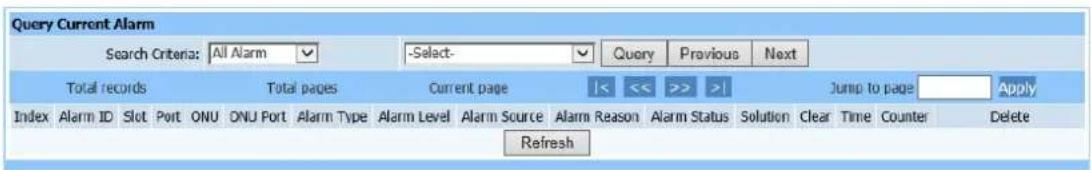
text_image
Query Current Alarm Search Criteria: All Alarm -Select- Query Previous Next Total records Total pages Current page |<< >> >| Jump to page Apply Index Alarm ID Slot Port ONU ONU Port Alarm Type Alarm Level Alarm Source Alarm Reason Alarm Status Solution Clear Time Counter Delete RefreshFigure 20-5
This query page is used to find all alarms. Query condition divides into alarm, alarm type, alarm level, alarm source, alarm reason and alarm time. Each query condition contains many kinds of conditions. Query current alarm according to user need.
20.6. History Alarm
Query page is shown as Figure (20-6):
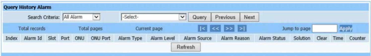
text_image
Query History Alarm Search Criteria: All Alarm Select- Query Previous Next Total records Total pages Current page Jump to page Apply Index Alarm Id Slot Port ONU ONU Port Alarm Type Alarm Level Alarm Source Alarm Reason Alarm Status Solution Clear Time Counter RefreshFigure 20-6
This query page is used to find history alarm. Inquiry mode is as the same of current alarm query.
20.7. Auto Alarm
Query page is shown as Figure (20-7):
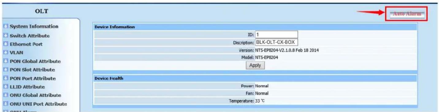
text_image
OLT System Information Switch Attribute Ethernet Port VLAN PON Global Attribute PON Slot Attribute PON Port Attribute LLID Attribute ONU Global Attribute ONU UNI Port Attribute Device Information ID: 1 Discription: BLK-OLT-CX-BOX Version: NTS-EP8204-V2.1.0.8 Feb 18 2014 Model: NTS-EP8204 Apply Device Health Power: Normal Fan: Normal Temperature: 33 ℃ Auto AlarmFigure 20-7
Click Auto Alarm, it is the red button in the top right corner of the window; an alarm window will appear as shown in Figure (20-8):
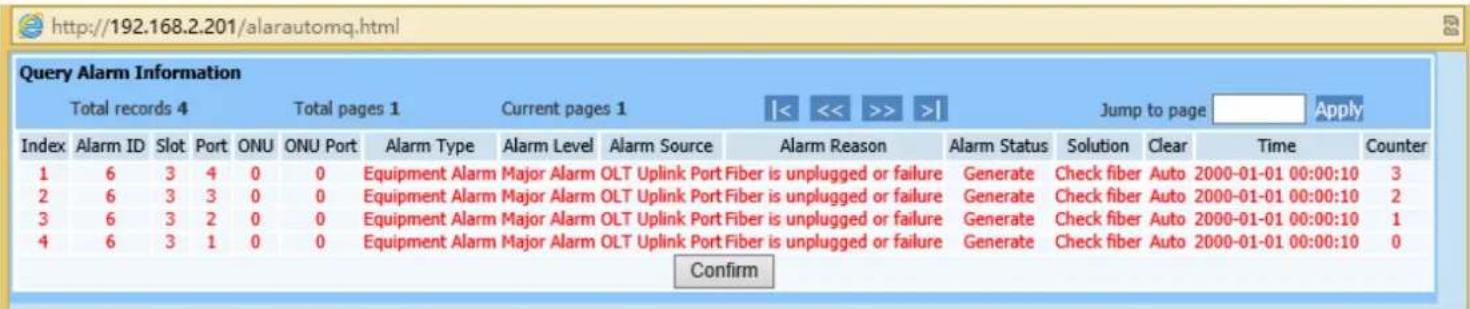
text_image
http://192.168.2.201/alarautomq.html Query Alarm Information Total records 4 Total pages 1 Current pages 1 Jump to page Apply Index Alarm ID Slot Port ONU ONU Port Alarm Type Alarm Level Alarm Source Alarm Reason Alarm Status Solution Clear Time Counter 1 6 3 4 0 0 Equipment Alarm Major Alarm OLT Uplink Port Fiber is unplugged or failure Generate Check fiber Auto 2000-01-01 00:00:10 3 2 6 3 3 0 0 Equipment Alarm Major Alarm OLT Uplink Port Fiber is unplugged or failure Generate Check fiber Auto 2000-01-01 00:00:10 2 3 6 3 2 0 0 Equipment Alarm Major Alarm OLT Uplink Port Fiber is unplugged or failure Generate Check fiber Auto 2000-01-01 00:00:10 1 4 6 3 1 0 0 Equipment Alarm Major Alarm OLT Uplink Port Fiber is unplugged or failure Generate Check fiber Auto 2000-01-01 00:00:10 0 ConfirmFigure 20-8
Clicking Auto Alarm, page as shown in Figure 20-8 will pop up and refresh every 30 seconds. Any alarm on OLT will report to this page after refreshing.
21. Statistics Management
21.1. Statistic Task
Web configuration page is shown as Figure (21-1):
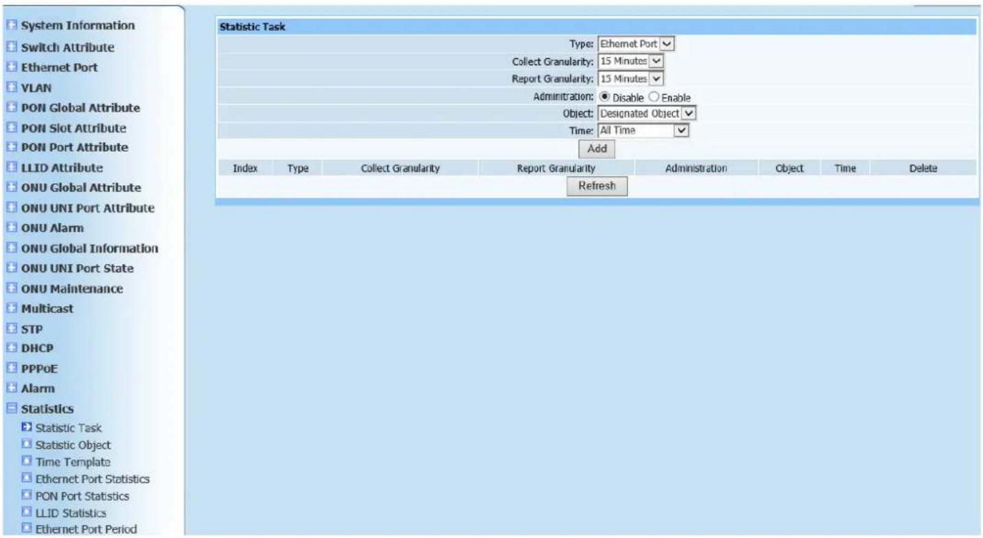
text_image
System Information Switch Attribute Ethernet Port VLAN PON Global Attribute PON Slot Attribute PON Port Attribute LLID Attribute ONU Global Attribute ONU UNI Port Attribute ONU Alarm ONU Global Information ONU UNI Port State ONU Maintenance Multicast STP DHCP PPPoE Alarm Statistics Statistic Task Statistic Object Time Template Ethernet Port Statistics PON Port Statistics LLID Statistics Ethernet Port Period Statistic Task Type: Ethernet Port Collect Granularity: 15 Minutes Report Granularity: 15 Minutes Administration: Disable Enable Object: Designated Object Time: All Time Add Index Type Collect Granularity Report Granularity Administration Object Time Delete RefreshFigure 21-1
This page is to configure statistic task to add statistical object. Configure according to Figure 21-1. Click Add to automatically refresh the statistics task list after configuration is completed. Check if the configured parameters have been added into list.
21.2. Statistic Object
Web configuration page is shown as Figure (21-2):
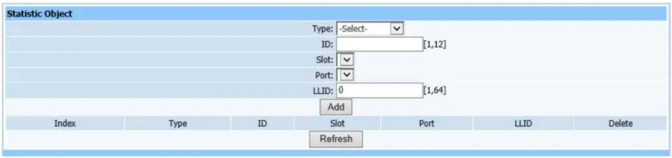
text_image
Statistic Object Type: -Select- ID: [1,12] Slot: Port: LLID: 0 [1,64] Add Index Type ID Slot Port LLID Delete RefreshFigure21-2
This page is to add statistic object, it can specific to certain port.
21.3. Time Template
Web configuration page is shown as Figure (21-1):
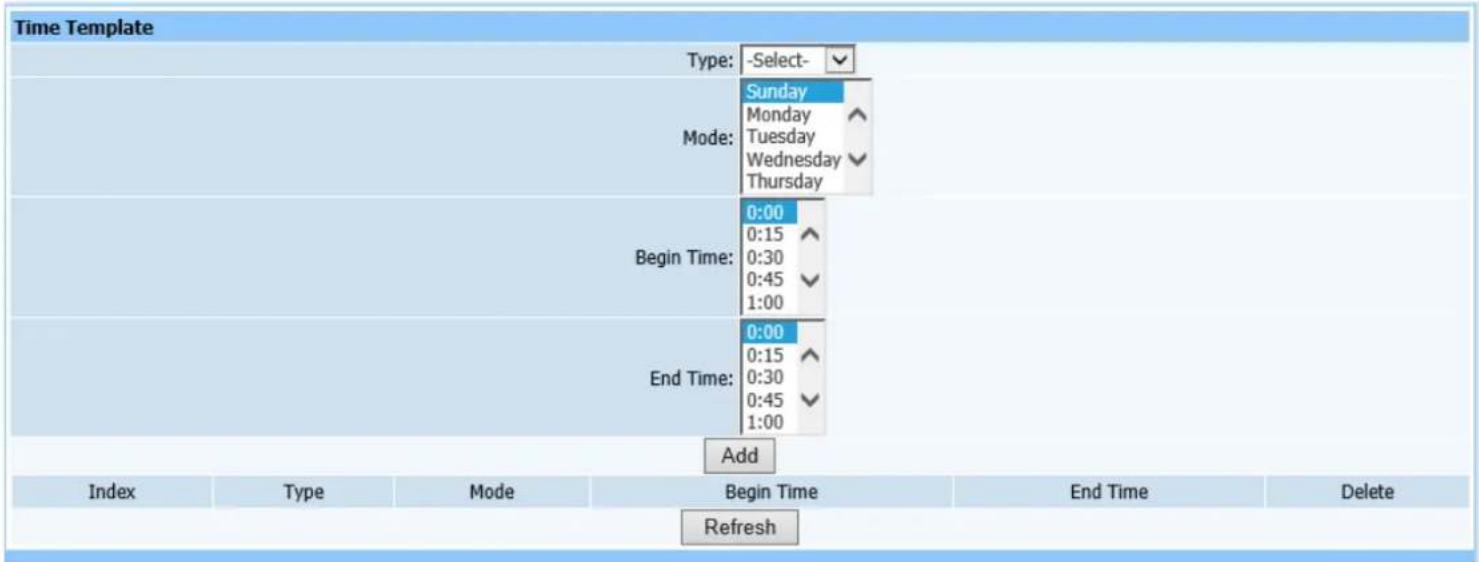
text_image
Time Template Type: -Select- Sunday Monday Tuesday Wednesday Thursday Mode: Begin Time: 0:00 0:15 0:30 0:45 1:00 End Time: 0:00 0:15 0:30 0:45 1:00 Add Index Type Mode Begin Time End Time Delete RefreshFigure 21-3
If a specific time is configured in Statistic Task item, the time slot must be configured in the time template. Select object type, time mode and start time and end time.
21.4. Ethernet port Statistics
Web configuration page is shown as Figure (21-4):
| Ethernet Port Statistics | |
| Slot: | -Select-✓ |
| Port: | -Select-✓ |
| InOctets: | |
| InUcastpkts: | |
| InMultipkts: | |
| InBroadpkts: | |
| InErrs: | |
| InNoerrs: | |
| InPause: | |
| OutOctets: | |
| OutUcastpkts: | |
| OutMultipkts: | |
| OutBroadpkts: | |
| OutErrs: | |
| OutNoerrs: | |
| OutPause: | |
| Less64b: | |
| Size64b: | |
| Size65To127b: | |
| Size128To255b: | |
| Size256To511b: | |
| Size512To1023b: | |
| Size1024To1518b: | |
| Size1519b: | |
| CrcErrs: | |
| DropEvents: | |
| SingLecollisions: | |
| Multicollisions: | |
| Collisions: | |
| CarrierErrs: | |
| AlignmentErrs: | |
| Deferreds: | |
| Latecollisions: | |
| Excessivecollisions: | |
| Query | Refresh |
Figure 21-4
This query page is used to find Ethernet port information.
21.5. PON Port Statistics
Query page is shown as Figure (21-5):
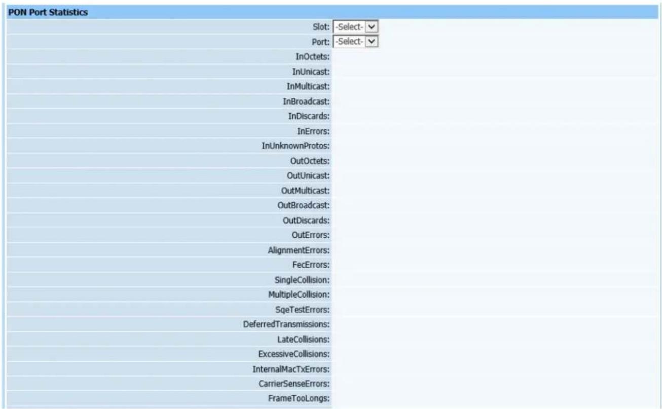
text_image
PON Port Statistics Slot: -Select- Port: -Select- InOctets: InUnicast: InMulticast: InBroadcast: InDiscards: InErrors: InUnknownProtos: OutOctets: OutUnicast: OutMulticast: OutBroadcast: OutDiscards: OutErrors: AlignmentErrors: FecErrors: SingleCollision: MultipleCollision: SqTestErrors: DeferredTransmissions: LateCollisions: ExcessiveCollisions: InternalMacTxErrors: CarrierSenseErrors: FrameTooLongs:Figure 21-5
This query page is used to find statistical information of PON port.
21.6. LLID Statistics
Query page is shown as Figure (21-6):
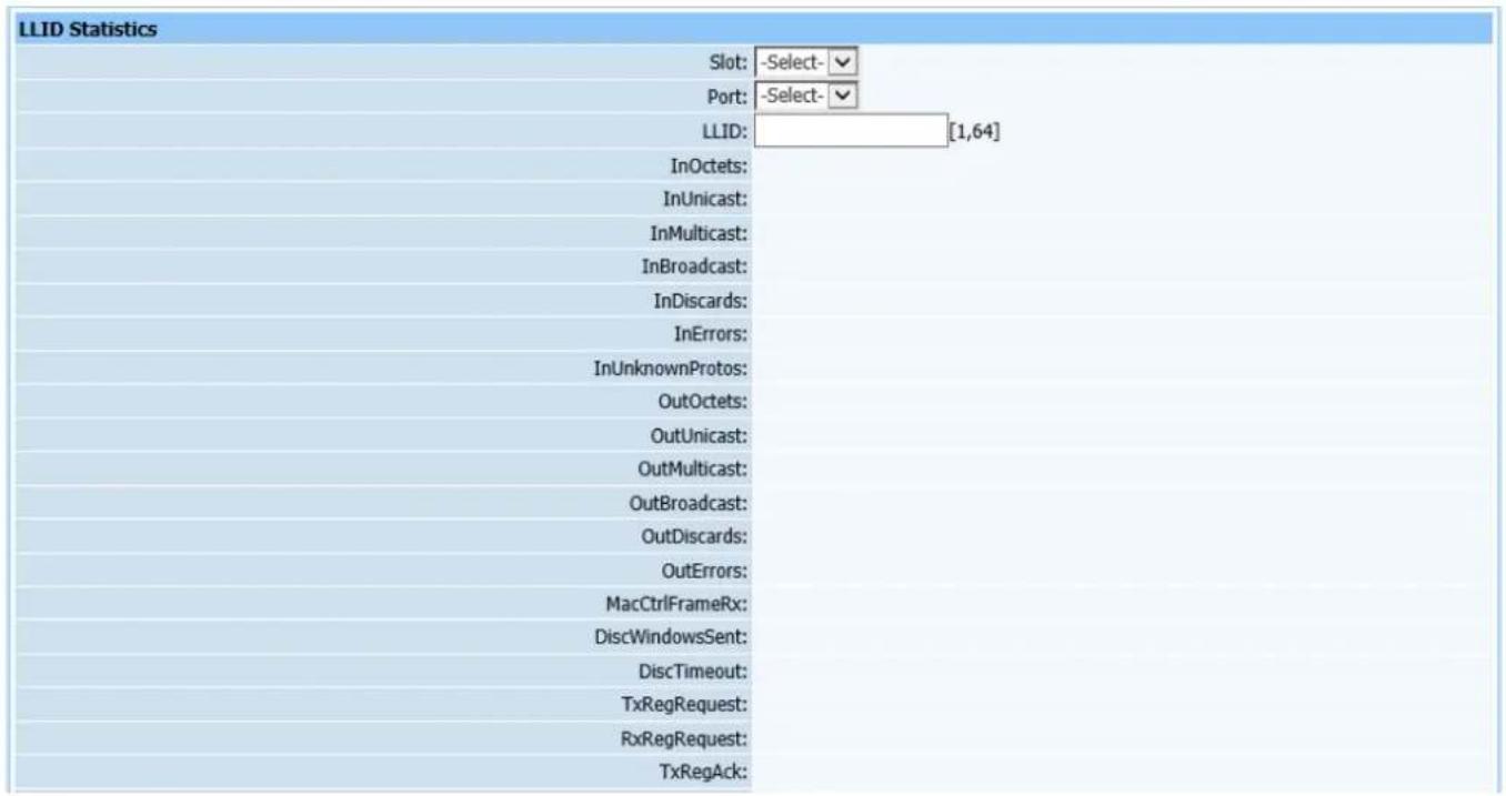
text_image
LLID Statistics Slot: -Select- Port: -Select- LLID: [1,64] InOctets: InUnicast: InMulticast: InBroadcast: InDiscards: InErrors: InUnknownProtos: OutOctets: OutUnicast: OutMulticast: OutBroadcast: OutDiscards: OutErrors: MacCtrlFrameRx: DiscWindowsSent: DiscTimeout: TxRegRequest: RxRegRequest: TxRegAck:Figure 21-6
This query page is used to find statistical information of LLID port.
21.7. Ethernet Port Period Statistics
Query page is shown as Figure (21-7):
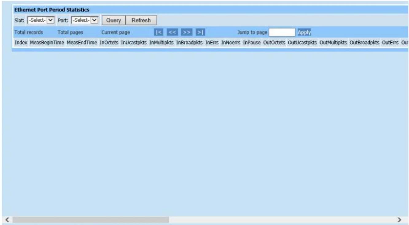
text_image
Ethernet Port Period Statistics Slot: -Select-▼ Port: -Select-▼ Query Refresh Total records Total pages Current page |<< >> | Jump to page Apply Index MeasBeginTime MeasEndTime InOctets InUcastpkts InMultipkts InBroadpkts InErrs InNoerrs InPause OutOctets OutUcastpkts OutMultipkts OutBroadpkts OutErrs OutFigure 21-7
This page is for period statistics of OLT Ethernet port. If a specific time is configured in Add Statistic Task above, it means to count information within specific time.
21.8. PON Port Period Statistics
Query page is shown as Figure (21-8):

text_image
PON Port Period Statistics Slot: -Select-▼ Port: -Select-▼ Query Refresh Total records Total pages Current page |< << >> >| Jump to page Apply Index MeasBeginTime MeasEndTime InOctets InOctets InMulticast InBroadcast InDiscards InErrors InUnknownProtos OutOctets OutUnicast OutMulticast OutBroadcast OutDFigure 21-8
Inquiry mode is as the same of period statistics of OLT Ethernet port.
21.9. LLID Period Statistics
Query page is shown as Figure (21-9):
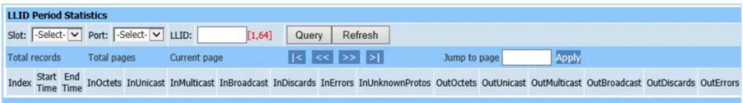
text_image
LLID Period Statistics Slot: -Select-▼ Port: -Select-▼ LLID: [1,64] Query Refresh Total records Total pages Current page |< << >> >| Jump to page Apply Index Start Time End Time InOctets InUnicast InMulticast InBroadcast InDiscards InErrors InUnknownProtos OutOctets OutUnicast OutMulticast OutBroadcast OutDiscards OutErrorsFigure 21-9
Inquiry mode is as the same of period statistics of PON port.
21.10. ONU Performance Analysis
Query page is shown as Figure (21-10):
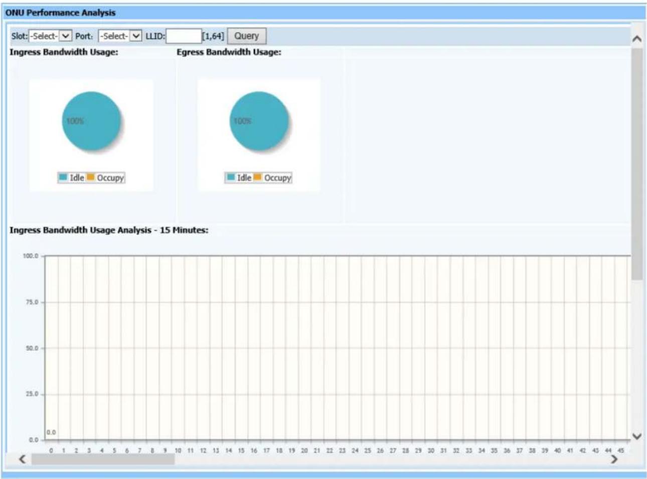
pie
| Usage Type | Percentage | |------------|----------| | Idle | 100% | | Occupy | 100% |Figure 21-10
This page is to analyze ONU performance, including overall bandwidth use, ratio between upstream and downstream, 15 minute history showing performance statistics histogram of upstream and downstream.
21.11. PON Performance Analysis
Query page is shown as Figure (21-11):
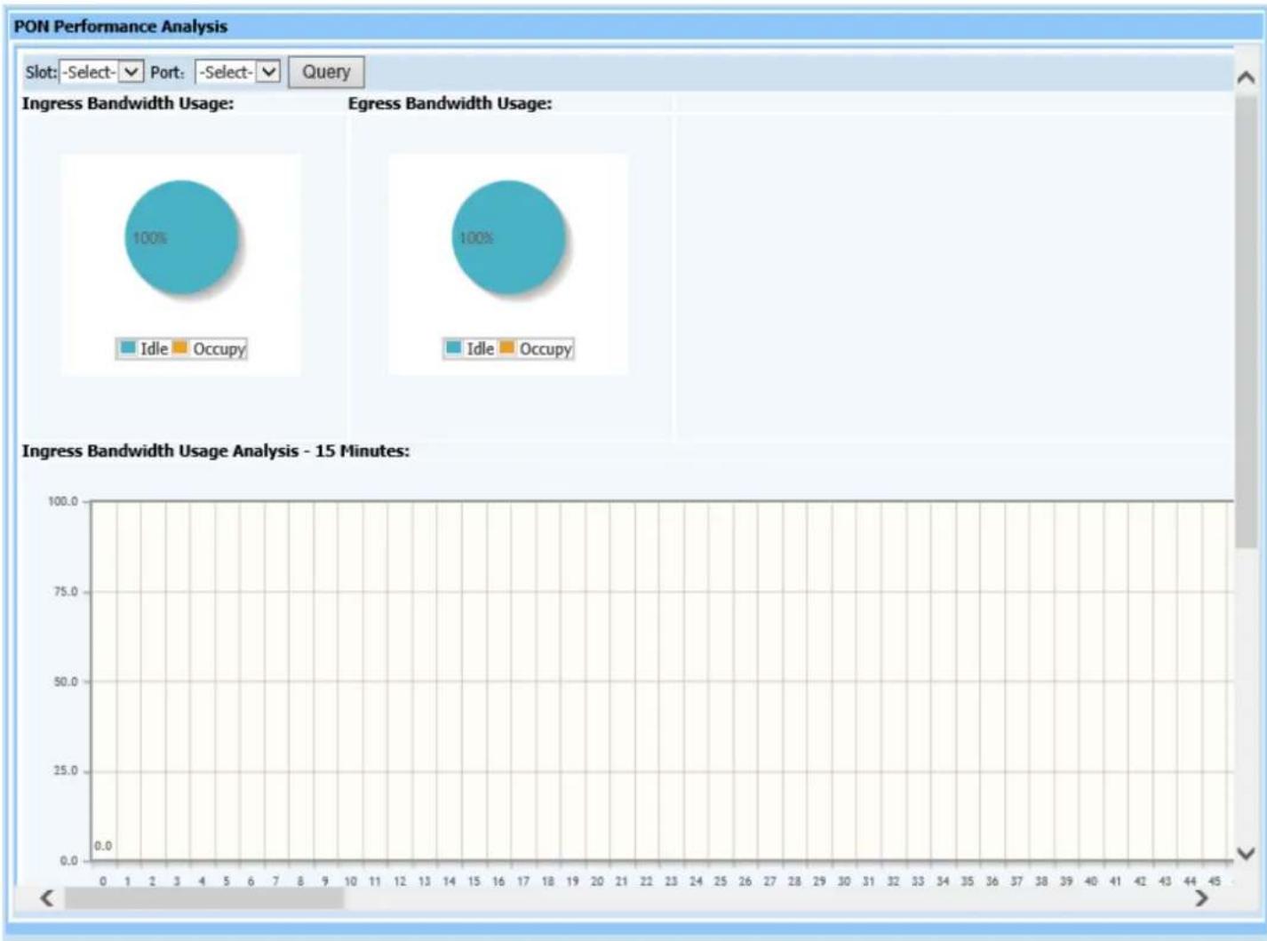
bubble
| Usage Type | Percentage | |------------|----------| | Idle | 100% | | Occupy | 100% |Figure 21-11
This query page is used to analyze PON port performance, including overall bandwidth use ratio between upstream and downstream and 15 minute history showing performance statistics histogram of upstream and downstream.
22. System Maintenance
22.1. Network Parameter
Web configuration page is shown as Figure (22-1):
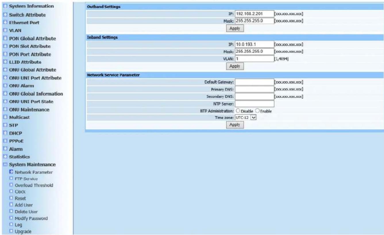
text_image
System Information Switch Attribute Ethernet Port VLAN PON Global Attribute PON Slot Attribute PON Port Attribute LLID Attribute ONU Global Attribute ONU UNI Port Attribute ONU Alarm ONU Global Information ONU UNI Port State ONU Maintenance Multicast STP DHCP PPPoE Alarm Statistics System Maintenance Network Parameter FTP Service Overload Threshold Clock Reset Add User Delete User Modify Password Log Upgrade Outband Settings IP: 192.168.2.201 [xxx.xxx.xxx.xxx] Mask: 255.255.255.0 [xxx.xxx.xxx.xxx] Apply Inband Settings IP: 10.0 193.1 [xxx.xxx.xxx.xxx] Mask: 255.255.255.0 [xxx.xxx.xxx.xxx] VLAN: 1 [1,4(94)] Apply Network Service Parameter Default Gateway: Primary DNS: Secondary DNS: NTP Server: NTP Administration: Disable Enable Time zone: UTC-12 ApplyFigure 22-1
This page is to configure outband, inband and network service parameters. Configure according to Figure 22-1. Click Apply after configuration is completed. A prompt will pop up to show if configuration has been completed successfully.
22.2. FTP Service
Web configuration page is shown as Figure (22-2):
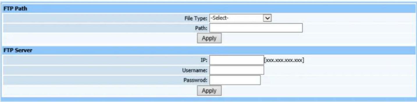
text_image
FTP Path File Type: -Select- Path: Apply FTP Server IP: [xxx.xxx.xxx.xxx] Username: Password: ApplyFigure 22-2
This page is to configure FTP service parameters. Configure according to page prompting. Click Apply after configuration is completed. A prompt will pop up to show if configuration has been completed successfully.
22.3. Overload Threshold
Web configuration page is shown as Figure (22-3):
| Overload Threshold | ||
| CPU Usage Threshold: 80 | [60,90]% | |
| CPU Usage Clear Threshold: 70 | [60,90]% | |
| Memory Usage Threshold: 80 | [60,90]% | |
| Memory Usage Clear Threshold: 70 | [60,90]% | |
| Temperature Reporting Threshold: 55 | [30,80] ℃ | |
| Temperature Clear Threshold: 50 | [30,80] ℃ | |
| Apply | ||
Figure 22-3
This page is to configure overload threshold parameters.
22.4. Clock
Web configuration page is shown as Figure (22-4):

text_image
Clock Time: 2000-01-01 06:53:38 【Year-Month-Day Hour:Minute:Second】 ApplyFigure 22-4
This page is to set time in real time, which is convenient for statistical
management.
22.5. Reset
Web configuration page is shown as Figure (22-5):

text_image
模块复位 Slot: -Select- PON1 Ap DeviceFigure22-5
This page is used to reset modules. Operation shall be done as required.
22.6. Add User
Web configuration page is shown as Figure (22-6):
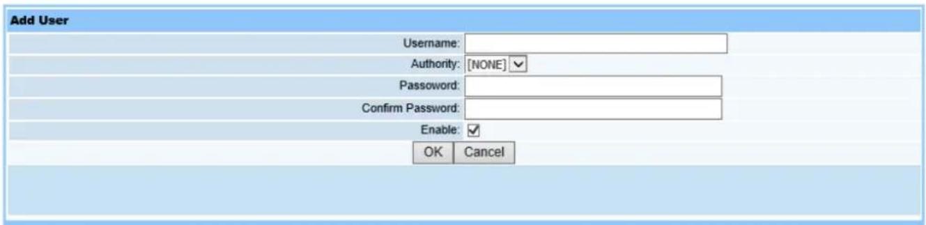
text_image
Add User Username: Authority: [NONE] Password: Confirm Password: Enable: OK CancelFigure 22-6
Only the administrator has operating authorization to add users and assign usernames. Authorization divides into no access, root and guest. Configure passwords, click Enable, and then click OK to display configuration information.
22.7. Delete User
Web operation interface is shown as in Figure (22-7):

text_image
Delete User Username: root guest OK CancelFigure22-7
This page is to delete users. Select desired username, and click OK. If it shows operation successfully completed, user has been deleted.
22.8. Delete User
Web operation interface is shown as in Figure (22-8):
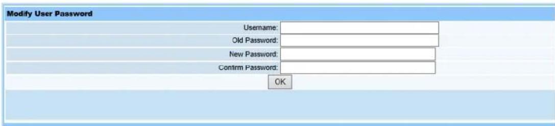
text_image
Modify User Password Username: Old Password: New Password: Confirm Password: OKFigure22-8
This page is to configure the login username and password for your current guest or administrator account.
22.9. Log
Query page is shown as Figure (22-9):
| Log | ||||
| Total records 120 | Total pages 3 | Current page 1 | |<<<>>> | Jump to pageApply |
| Index | IP | Username | Time | Operation |
| 1 | 192.168.2.11 | 01/JAN/2000:06:53:38 | Show Clock | |
| 2 | 192.168.2.11 | 01/JAN/2000:06:52:37 | Show Overload Threshold | |
| 3 | 192.168.2.11 | 01/JAN/2000:06:52:37 | Show Overload Threshold | |
| 4 | 192.168.2.11 | 01/JAN/2000:06:52:36 | Show Overload Threshold | |
| 5 | 192.168.2.11 | 01/JAN/2000:06:51:46 | Show FTP Service | |
| 6 | 192.168.2.11 | 01/JAN/2000:06:50:18 | Show Network Parameter | |
| 7 | 192.168.2.11 | 01/JAN/2000:06:50:18 | Show Network Parameter | |
| 8 | 192.168.2.11 | 01/JAN/2000:06:50:18 | Show Network Parameter | |
| 9 | 192.168.2.11 | 01/JAN/2000:05:37:21 | Show Time Template | |
| 10 | 192.168.2.11 | 01/JAN/2000:05:37:02 | Show Time Template | |
| 11 | 192.168.2.11 | 01/JAN/2000:01:35:49 | Show Statistic Object | |
| 12 | 192.168.2.11 | 01/JAN/2000:01:34:23 | Show Statistic Task | |
| 13 | 192.168.2.11 | 01/JAN/2000:01:33:48 | Show Alarm Define Table | |
| 14 | 192.168.2.11 | 01/JAN/2000:01:33:21 | Show Statistic Task | |
| 15 | 192.168.2.11 | 01/JAN/2000:01:28:15 | Show Alarm Define Table | |
| 16 | 192.168.2.11 | 01/JAN/2000:01:27:51 | Show Alarm Filter Time | |
| 17 | 192.168.2.11 | 01/JAN/2000:01:27:09 | Show Alarm Mask | |
| 18 | 192.168.2.11 | 01/JAN/2000:01:23:23 | Show PPPoE Statistic | |
| 19 | 192.168.2.11 | 01/JAN/2000:01:23:04 | Show ONU Register Information | |
| 20 | 192.168.2.11 | 01/JAN/2000:01:23:04 | Show ONU Register Information | |
| 21 | 192.168.2.11 | 01/JAN/2000:03:10:50 | Show ONU UNI Port Pause | |
| 22 | 192.168.2.11 | 01/JAN/2000:03:07:22 | Show ONU Global Active PON Port | |
| 23 | 192.168.2.11 | 01/JAN/2000:03:04:59 | Show ONU Global Holdover | |
| 24 | 192.168.2.11 | 01/JAN/2000:03:04:09 | Show ONU Global Holdover | |
| 25 | 192.168.2.11 | 01/JAN/2000:03:03:26 | Show ONU Global FEC | |
| 26 | 192.168.2.11 | 01/JAN/2000:03:02:53 | Show ONU Global FEC | |
| 27 | 192.168.2.11 | 01/JAN/2000:03:02:10 | Show ONU Global Multicast Fastleave | |
| 28 | 192.168.2.11 | 01/JAN/2000:03:01:14 | Show ONU Global Multicast Mode | |
| 29 | 192.168.2.11 | 01/JAN/2000:02:53:03 | Show PON Port Health | |
| 30 | 192.168.2.11 | 01/JAN/2000:02:51:05 | Show PON Port ONU Authentication Table | |
| 31 | 192.168.2.11 | 01/JAN/2000:02:45:08 | Show PON Port ONU Authentication Mode | |
Figure 22-9
This page shows saved logged detailed information for operation users. User can query which user has configured OLT information.
22.10. Upgrade
Select Upgrade in main item System Maintenance on left of the Web, click to switch to upgrade page. Interface is shown as in Figure (22-10):
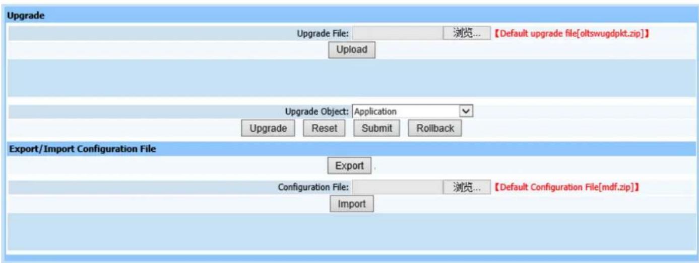
text_image
Upgrade Upgrade File: 浏览... 【Default upgrade file[oltswugdpkt.zip]】 Upload Upgrade Object: Application Upgrade Reset Submit Rollback Export/Import Configuration File Export Configuration File: 浏览... 【Default Configuration File[mdf.zip]】 ImportFigure22-10
Upgrading steps:
- Browse and upload upgrade package click Upload, wait approximately 15 seconds.
- After package is successfully uploaded, select corresponding upgrade module in pull-down menu of upgrade object.
Application: equipment software and WEB;
Default Configuration Data: restore default configuration parameter;
Firmware: upgrade PON firmware;
All: all three parts above.
During upgrading, it can select corresponding modules according to the actual situation and then click Upgrade button till it prompts successful operation.
Click Reset button, view the version or system is normal running or not after restart. Click Submit when it's normal running, otherwise click RollBack to return last version.
- Export configuration data: Click Export to export configuration data.
- Import configuration data: Click Browse and select upload configuration file
mdf.zip package, then click Import. Select Yes when prompted to import. Configuration data will take effect when it has restarted.
22.11. Restore
Web configuration page is shown as Figure (22-11):

This page is to restore factory settings for OLT. Click Restore, OLT will restore factory settings.
Note: As the factory recovery resets all informations configured, please be careful for using this operation.