71 - Multimeter APPA - Free user manual and instructions
Find the device manual for free 71 APPA in PDF.

User questions about 71 APPA
0 question about this device. Answer the ones you know or ask your own.
Ask a new question about this device
Download the instructions for your Multimeter in PDF format for free! Find your manual 71 - APPA and take your electronic device back in hand. On this page are published all the documents necessary for the use of your device. 71 by APPA.
USER MANUAL 71 APPA
User Manual
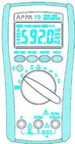
APPA
71/72/73
CE
APPA
A General Development Technology, Only Easy
Safety Alert Symbol : △
READ and UNDERSTAND all safety alert symbols : △ in this manual.
Failure to read and understand safety instructions can result in INJURY or DEATH
Limited Warranty
This meter is warranted to the original purchaser against defects in material and workmanship for 1 year from the date of purchase. During this warranty period, Manufacturer will, at its option, replace or repair the defective unit, subject to verification of the defect or malfunction. This warranty does not cover fuses, disposable batteries, or damage from abuse, neglect, accident, unauthorized repair, alteration, contamination, or abnormal conditions of operation or handling.
Any implied warranties arising out of the sale of this product, including but not limited to implied warranties of merchantability and fitness for a particular purpose, are limited to the above. The manufacturer shall not be liable for loss of use of the instrument or other incidental or consequential damages, expenses, or economic loss, or for any claim or claims for such damage, expense or economic loss. Some states or countries laws vary, so the above limitations or exclusions may not apply to you.
APPA TECHNOLOGY CORP.
http://www.appatech.com
Table of Contents
| Title | Page |
| Safety | 03 |
| "ΔWarning" and "ΔCaution" Alert Symbol Statements | 03 |
| Warning and Cautions | 03 |
| Symbols as Marked on The Meter | 05 |
| Symbols and Terms in The Manual | 06 |
| Safety Compliance And Certification | 07 |
| Safety Compliance | 07 |
| Safety Certification | 07 |
| Introduction | 08 |
| Unpacking and Inspection | 08 |
| Environmental Conditions | 08 |
| The Meter Description | 08 |
| Making Basic Measurements | 09 |
| Preparation and Caution Before Measurement | 09 |
| Measuring AC/DC Voltage and Frequency | 10 |
| Measuring Resistance | 11 |
| Measuring DC μA and AC / DC A Current | 12 |
| Measuring Capacitance | 14 |
| Testing for Diode and Continuity | 15 |
| Features | 16 |
| Features Description | 16 |
| Features Available vs Functions | 16 |
| Using The Features | 17 |
| Manual Ranging and Auto Ranging | 17 |
| Min Max Recording Mode | 17 |
| RS-232 | 18 |
| Display Hold | 18 |
| Backlight | 19 |
| Auto Power Off (Battery Saver) | 19 |
| Disable Auto Power Off | 20 |
| Maintenance | 20 |
| Cleaning and Storage | 20 |
| Fuse Replacement | 21 |
| Battery Replacement | 21 |
| Trouble Shooting | 22 |
| Basic Trouble Shooting | 22 |
| Testing the Fuse and Test Leads | 22 |
| Specification | 23 |
| General Specification | 23 |
| Electrical Specification | 24 |
| Terms in the Specification | 28 |
Safety
Safety
"Warning" and "Caution" Alert Symbol Statement :
| ⚠ Warning" Alert Symbol | |
| A "⚠Warning" Statement identifies hazardous conditions and actions that could cause BODILY HARM or DEATH. |
| "⚠ Caution" Alert Symbol | |
| A "⚠Caution" Statement: identifies conditions and actions that could DAMAGE the Meter or the equipment under test. |
"⚠️Warnings" and "⚠️ Cautions";
| Warnings | |
| ·When using test leads or probes, keep your fingers behind the finger guards. ·Remove test lead from Meter before opening the battery door or Meter case. | |
3
Safety
- Use the Meter only as specified in this manual or the protection by the Meter might be impaired.
- Always use proper terminals, switch position, and range for measurements.
- Never attempt a voltage measurement with the test lead inserted into the A input terminal.
- Verify the Meter's operation by measuring a known voltage. If in doubt, have the Meter serviced.
- Do not apply more than the rated voltage, as marked on Meter, between terminals or between any terminal and earth ground.
- Do not attempt a current measurement when the open voltage is above the fuse protection rating. Suspected open circuit voltage can be checked with voltage function.
- Only replace the blown fuse with the proper rating as specified in this manual.
- Use caution with voltages above 30 Vac rms, 42 Vac peak, or 60 Vdc. These voltages pose a shock hazard.
- To avoid false readings that can lead to electric shock and injury, replace battery as soon as low battery indicator 📄 appears.
- Disconnect circuit power and discharge all high-voltage capacitors before testing resistance, continuity, diodes, or capacitance.
- Do not use Meter around explosive gas or vapor.
- To reduce the risk of fire or electric shock do not expose this product to rain or moisture.
Safety

⚠️ Cautions
- Disconnect the test leads from the test points before changing the position of the function rotary switch.
- Never connect a source of voltage with the function rotary switch in / / = A/Hz position.
- Do not expose Meter to extremes in temperature or high humidity.
- Never set the meter in = A function to measure the voltage of a power supply circuit in equipment that could result in damage the meter and the equipment under test.
Symbols as Marked on The Meter :
\~ : AC (Alternating Current)
: DC (Direct Current)
4 : Caution, Risk of Electric shock. To alert you to the presence of a potentially hazardous voltage.
⚠️ : Caution, Risk of Danger. Refer to ⚠Warnings and ⚠ Cautions in the manual.
☐ : Double Insulation protection against electric shock.
CE : Conforms to European Union directives.
Safety
Symbols and Terms in The Manual
Symbols
△ : Caution, Risk of Danger.
⚠ Warning: Identifies hazardous conditions and actions that could cause BODILY HARM or DEATH
Caution : Identifies conditions and actions that could DAMAGE the meter or equipment under test.
→: Fuse.
Terms :
CAT Level : Over Voltage Category Level, indicates measurement can be performed at which measuring circuit level. The different level measuring circuit has different high transient stresses voltage.
PER IEC 1010 OVERVOLTAGE INSTALLATION CATEGORY
OVERVOLTAGE CATEGORY Environment of OVERVOLTAGE
Equipment of OVERVOLTAGE CATEGORY 1 is equipment for connection to circuits in which measurements are taken to limit the transient overvoltage to an appropriate low level. Note examples include protected electronic circuits.
OVERVOLTAGE CATEGORY
Equipment of OVERVOLTAGE CATEGORY II is energy consuming equipment to be supplied from this fixed installation.
OVERVOLTAGE CATEGORY III
Equipment of OVERVOLTAGE CATEGORY III is equipment in fixed installations. Note examples include switches in this fixed installation and some equipment for industrial use with permanent connection to the fixed installation.
OVERVOLTAGE CATEGORY IV
Equipment of OVERVOLTAGE CATRGORY IV is for use at the origin of the installations. Note examples include electricity meters and primary over-current protection equipment.
Safety Compliance And Certification
PER IEC1010 Pollution degree
POLLUTION
Addition of foreign matter, solid, liquid or gaseous (ionized gases), that may produce a reduction of dielectric strength or surface resistivity.
POLLUTION degree
For the purpose of evaluating spacing of this product, the following degrees of POLLUTION in the microenvironment are defined.
POLLUTION DEGREE 1
No POLLUTION or only dry, non-conductive POLLUTION occurs. The POLLUTION has no influence.
POLLUTION DEGREE 2
Normal POLLUTION only non-conductive POLLUTION occurs. Occasionally, however, a temporary conductivity caused by condensation must be expected.
POLLUTION DEGREE 3
Conductive POLLUTION occurs, or dry, non-conductive POLLUTION occurs which becomes conductive due to condensation, which is expected.
NOTE : In such conditions equipment is normally protected against exposure to direct sunlight, precipitation, and full wind pressure, but neither temperature nor humidity is controlled.
Safety Compliance And Certification
Safety compliance
The Meter conform to CENELEC LVD (Low-Voltage rective) 73/23/EEC and EMC (Electromagnetic Compatibility directive) 89/336/EEC
The Meter meet the requirements to IEC 61010-1 (2001), EN 61010-1 (2001), UL 3111-1 (Jan.1994) CSA C22.2 NO.1010-1-92 +A2: Feb. 1997
Safety Certification : CE
Introduction
Introduction
Unpacking and Inspection
Upon removing your new Digital Multimeter from its packing.
you should have the following items.
-
Digital Multimeter.
-
Test lead set (one black, on red)
-
User Manual.
-
Protective holster.
Environmental Conditions
This product is safe at least under the following conditions:
-
Indoor Use
-
Altitude up to 2000 Meter
-
Operating Temperature and Relative Humidity : Non-condensing ≤10°C, 11°C \~ 30°C (≤80% R.H) 31°C \~ 40°C (≤75% R.H), 41°C \~ 50°C (≤45% R.H).
-
Storage Temperature and Relative Humidity : -20°C \~ 60°C
(0 \~ 80% R.H) when battery removed from Meter.
-
Pollution degree 2
-
Installation category: The standard 70 series models meet the requirements for double insulation to IEC 61010-(2001), EN61010 (2001), UL3111-1(6.1994), CSA C22.2 NO.1010-1-92 to terminals:
V/Ω/μA : Cat. IV 600 Volts, Cat. III 1000V
A : Cat. IV 500 Volts for 72/73
-
Shock Vibration : Sinusoidal vibration per Mil-T-28800E (5 \~55 Hz, 3g maximum).
-
Droop Protection : 4 feet droop to hardwood on concrete floor.
Making Basic Measurements
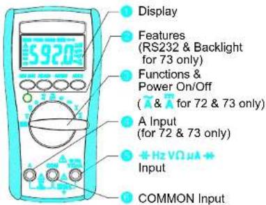
The Meter Description
Front Panel Illustration
1. 6000 counts LCD display.
2. Push-buttons for features.
3. Rotary switch to turn the Power On or Off and to select a
3. Rotary's function
4. Input Terminal for A current function. (For 72 & 73 only)
5. Input Terminal for all functions EXCEPT current (A) functions
6. Common (Ground reference) Input Terminal for all functions.
Making Basic Measurements
Making Basic Measurements
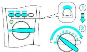
Preparation and Caution Before Measurement
△ : Observe the rules of
⚠️ Warnings and ⚠ Cautions.
When connecting the test leads to the DUT (Device Under Test) connect the common (COM) test lead before connecting the live lead; when removing the test leads removing the test live lead before removing the common test lead.
The figures on the following pages show how to make basic measurements.
Measuring AC/DC Voltage And Frequency
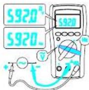
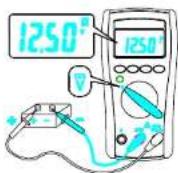
The non-zero display reading is normal when the meter test leads are open, which will not affect actual measurement accuracy. The meter will show zero or close to reading when the test leads are shorted. In reading AC voltage or current, reading-settling time increases to several seconds at the low end of AC voltage and current ranges in rms models.
Making Basic Measurements
Measuring Resistance
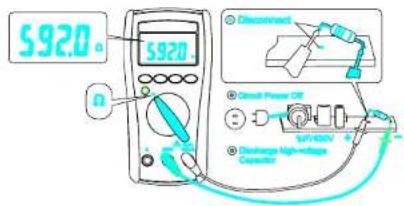

To avoid possible damage to the Meter or to the equipment under test, disconnect circuit power and discharge all high-voltage capacitors before measuring resistance.
Note - The Meter provides an open voltage ≤ -1.5V to the circuit under test that causes the diode, transistor junction to conduct so it is better to disconnect the resistance from the circuit to get a correct measurement.
The resistance of test leads is about 0.1 0.2 . To test the leads resistance, touch the probe tips together, for accuracy measurement in low resistance.
$$ \mathbf {R} _ {\text { UNKNOWN }} = \mathbf {R} _ {\text { MEASUREMENT }} - \mathbf {R} _ {\text { TESTLEAD }} $$
Making Basic Measurements
Measuring DC μA, DC A, AC A Current
(DCA, ACA for 72/73 only)
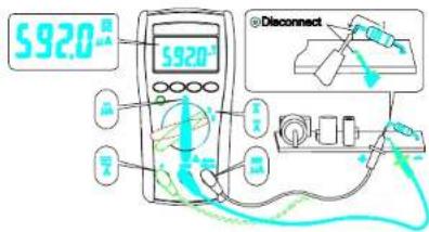

⚠ Warning
Never attempt an in-circuit measurement where the open-circuit potential to earth potential is greater than 500V for example a 3-phase system measurement, you may damage the Meter or be injured.
Making Basic Measurements

Caution
To avoid possible damage to the Meter or to the equipment under test, check the Meter's fuses before measuring current. Use the proper terminals, function, and range for your measurement. Never place the probes across (in parallel with) any circuit or component when the leads are plugged into the current terminals.
When measuring current, the Meter acts like an impedance such as 0.01Ω at AC/DC A (approximately 1.5KΩ at DC μA) in series with the circuit.
This loading effect of the Meter can cause measurement errors, loading effect error, especially in low impedance circuits.
For example: To measure a 1Ω impedance circuit will cause a -1% measuring error. The error percentage of the loading effect of the Meter is expressed as following:
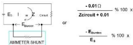
DC A input terminal is protected by a 1.5K PTC (600V rating) resistance.
Making Basic Measurements
Measuring Capacitance
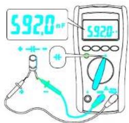

Caution
To avoid possible damage to the meter or to the equipment under test, disconnect circuit power and discharge all high-voltage capacitors before measuring capacitance. Use the DC voltage function to confirm that the capacitor discharged.
Note- To improve the measurement accuracy of small value capacitor, record the reading with the test leads open then subtract the residual capacitance of the Meter and leads from measurement.
C_UNKNOWN = C_MEASUREMENT - C_RESIDUAL
Making Basic Measurements
Testing for Diode and Continuity
Diode :
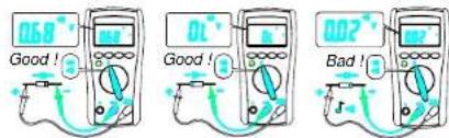
Continuity :

For in-circuit test, turn circuit power off and discharge the high-voltage capacitors through an appropriate resistance load.
Note - Use the diode test to check the semiconductor junction is good or bad. The Meter sends a current through the semiconductor junction to measure the voltage drop across the junction. A good junction drops between 0.4V to 0.9V .
Features
Features
Feature Description
The Meter has Features
Display Hold – Freezes the display.
Min Max Hold – Record the Max or Min reading of the
display.
Range – Selects the manual ranging mode. The default
mode is Automatic Range
RS232 - An optical isolated interface output for data com-
munication. (for 73 only)
Backlight ● - LCD display backlight.(for 73 only)
APO (Auto Power Off) (Battery Saver)
The Meter automatically enters "Sleep Mode" and blanks the display if the Meter is not used for 10 minutes. Press any of the feature buttons or change the rotary switch position to reset the time of APO. When RS232 output is active, the APO is disabled.
Features Available vs Functions
\~V =V Ω +4 =μA + Hz \~A =A
Manual Ranging and Auto Ranging
Note - The Range button is pressed to select manual ranging and to change ranges. When the Range button is pressed once, the AUTO indicator turns off. Press Range button to select the appropriate range for measurement you want to make. Press Range button and hold for 1 second to return to Autorange.
MIN MAX Record
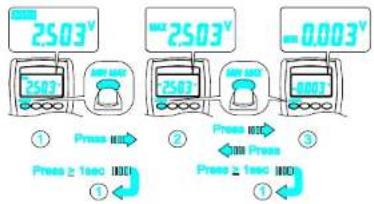
Using The Features
Note - Press HOLD button in MIN MAX mode to make the Meter stop updating the maximum and minimum value. When display Hold mode is nested in MIN MAX mode, the MIN MAX mode must be released before the display Hold.
RS232 (For 73 only)
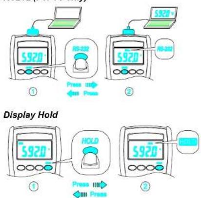
Note – Press the Hold button to toggle in and out of the display Hold mode. The MAX / MIN feature is unavailable when display Hold is active.
Using The Features
Backlight (For 73 only)
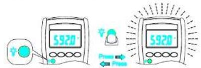
Note – Press the Backlight Button ☐ to toggle in and out the display backlight.
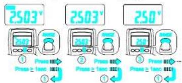
Auto Power Off (Battery Saver)
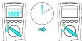
Note - If the Meter idles for more than 10 minutes, the Meter automatically turns the power off. When this happens, the LCD displaying-state of the Meter is saved. The Meter can be turned back on by pushing any button, the LCD displays the saved state. Pushing Hold button to disables the hold state. Any button pressed or rotary change resets the time of Auto-Power-OFF.
Maintenance
Disable Auto Power Off
Maintenance

- Do not attempt to repair this meter. It contains no user-serviceable parts. Repair or servicing should only be performed by qualified personal.
- Failure to observe this precaution can result in injury and can damage the meter.
Cleaning and storage
Periodically wipe the housing with a damp cloth and mild detergent. Dirt or moisture in the terminals can affect readings. If the Meter is not to be used for a long period, more than 60 days, remove the battery and store it separately.
Maintenance
Fuse Replacement (For 72 & 73 only)
Refer to the following figure to replace fuse :
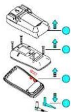

Caution
- Use ONLY a fuse with the amperage, interrupt, voltage, and speed rating specified.
• Fuse rating : 10A, 500V
Battery Replacement
Refer to the following figure to replace the battery :
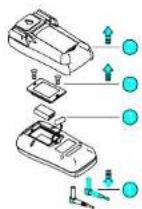

Caution
- Replace the battery as soon as the low battery indicator "☐" appears, to avoid false reading.
• 71 : Battery 1.5V x 2 72/73 : Battery 9V
Trouble Shooting
Trouble Shooting
Do not attempt to repair your Meter unless you are qualified to do so and have the relevant calibration, performance test and service information.
Basic Trouble Shooting
If the Meter fails, first check the battery, the battery connection, fuse, test leads, and replace as necessary. Review this manual to make sure that you are operating the Meter correctly.
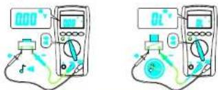
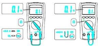
Testing the Fuse and Test Leads
Testing the fuse and test leads as shown below.
Testing the Fuse Testing the Test Leads
Specification
Specification
General Specifications
Display : 6000 counts updates 1.5/sec.
Polarity Indication : Automatic, positive implied, negative
indicated.
Overrange Indication: "OL" or "-OL"
Low Battery Indication: "☐" is displayed when the battery
voltage drops below operating voltage
Auto Power Off : Approx 10 minutes.
Operating Ambient
Non-condensing ≤10°C, 11°C \~ 30°C (≤80% R.H)
31°C \~ 40°C (≤75% R.H), 41°C \~ 50°C (≤45% R.H),
Storage Temperature : -20°C to 60°C , 0 to 80% R.H. when
battery removed from Meter.
1.5V x 2 IEC LR03, AM4 or AAA size (for APPA71)
Standard 9V battery NEDA 1604, IEC6F22, JIS006P
(for APPA72,73)
Battery Life : Alkaline 300 hours.
Dimensions (W x H x D)
76mm x 158mm x 38mm, without holster.
82mm x 164mm x 44mm, with holster.
Accessories : Battery (installed), Test leads and User
manual
Specification
Electrical Specifications
Accuracy is ± (% reading + number of digits) at 23°C ± 5°C, less than 80% R.H.
(1) DC / AC Volts
| Range | DC Accuracy | AC Accuracy |
| 600.0mV | ± (0.5% + 2dgt) | 50Hz / 60Hz sine wave only for 600.0mV range, ± (0.9% + 5dgt) 50Hz ~ 500Hz*1 |
| 6.000V | ||
| 60.00V | ||
| 600.0V | ||
| DC1000V / AC750V |
Over voltage protection : DC1000 V or AC 750 Vrms.
Input Impedance : 10MΩ // less than 100pF
CMRR / NMRR : (Common Mode Rejection Ratio)
(Normal Mode Rejection Ratio)
V_AC : CMRR > 60dB at DC, 50Hz / 60Hz
V_DC:CMRR > 100dB at DC,50Hz / 60Hz
NMRR > 50dB at DC, 50Hz / 60Hz
71 : Average sensing rms indication
72 / 73 : AC conversions are ac-coupled true rms responding,
calibrated to the sine wave input.
*1 The basic accuracy is specified for a sine wave below
4000 counts. Over 4000 counts, add 0.6% to the accuracy.
For a non-sine waves below 2000 counts, refer to the follow-
ing for accuracy
=1.5% addition error for C.F. from 1.4 to 3
Crest Factor : C.F.=Peak/RMS
Specification
(2) DC / AC Current
| Range | DC Accuracy | AC Accuracy | Voltage Burden |
| 600.0μA | ±(1.0% + 2 dgt) | N/A <4mV | /μA |
| 6000μA | |||
| 6.000A *2 | =(1.5% + 5 dgt)50Hz ~ 500Hz*1 | 2V max | |
| 10.00A *2 |
Overload Protection :
A input : 10A (500V) fast blow fuse
μA input : 600V rms.
* 1 AC Conversion Type : Conversion type and additional
specification are same as DC/AC Voltage.
* 2 (For 72 & 73 only)
(3) Resistance
| Range | Accuracy | Overload protection |
| 600.0Ω *2 | ± (0.7% + 2 dgt) | 600V rms |
| 6.000KΩ | ||
| 60.00KΩ | ||
| 600.0KΩ | ||
| 6.000MΩ | ± (1.0% + 2 dgt) | |
| 60.00MΩ *1 | ± (1.5% + 2 dgt) |
Open circuit Voltage : -1.3V approx.
* 1 < 100 dgt rolling
* 2 < 10 dgt rolling.
Specification
(4) Diode Check and Continuity
| Range Resolution Accuracy | ||
| 10 mV | ± (1.5% + 5 dgt)^* | |
* For 0.4V \~ 0.8V
Max.Test Current : 1.5mA
Max. Open Circuit Voltage : 3V
Overload Protection : 600V rms.
Continuity : Built-in buzzer sounds when resistance is less
than approximately 500Ω. Response time is approximately
100 msec.
(5) Frequency
| Range ** Sensitivity Accuracy | ||
| 6000Hz | 100mV rms* | Frequency : 0.1%±1digit |
| 60.00KHz | ||
| 600.0KHz | ||
| 6.000MHz 250mV rms | ||
| 60.00MHz 1V rms | ||
Overload Protection : 600V rms.
* Less than 20Hz, the sensitivity is 1.5V rms.
** Max.Sensitivity : <5 Vac rms
Specification
(6) Capacitance
| Range Accuracy | |
| 6.000nF | ± (1.9% + 8 dgt) |
| 60.00nF | |
| 600.0nF | |
| 6.000μF | |
| 60.00μF | |
| 600.0μF | |
| 6.000mF* | |
Overload Protection : 600V rms.
* < 100 dgt of reading rolling.
(7) Auto Power Off (APO)
If the Meter idles for more than 10 minutes, the Meter automatically turns the power off.
Terms In The Specification
Terms In The Specification
RMS
The physical meaning of RMS (Root Mean Square): If the heat energy, temperature, in a resistor produced by a AC signal during the periodic time T is the same as produced by a DC signal during the same time T then we know "The DC signal value is the RMS value of the AC signal"
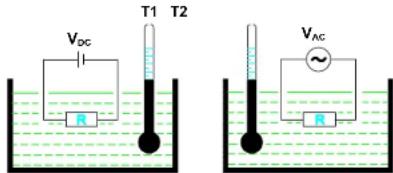
When T1 = T2,
The V_DC value is the V_RMS value of a V_AC signal
According to the definition of physical meaning we can derive the mathematic operation procedure to get a RMS value of a signal as following :
"Root < Mean < Square the signal"
Terms In The Specification
Average sensing RMS calibrated technical :
Most digital multimeters use an average sensing RMS calibrated technique of an electrical average circuit to measure RMS value of AC signals. This technique is scaling the output average value of the average sensing circuit by the ratio of RMS value to average value, for sine wave the ratio is 1.11. Unfortunately, this ratio varies widely as a function of the wave form, it will give grossly incorrect results in many cases. The table shows a few representative examples comparing RMS to average.
| Waveform Type 1 Volt Peak Amplitude | Crest Factor ( V_Peak /Vrms) | True rms Value | Average Re-sponding Circuit Cali-brated rms Value of Sine Waves Will Read | % of Reading Error ^a Using Average Re-sponding Circuit |
| 1.414 0.707V | 0.707V | 0% | ||
| 1.00 1.00V | 1.11V | +11.0% | ||
| 1.73 0.577V | 0.555V | -3.8% | ||
| Rectangular Pulse Train | 210 | 0.5V0.1V | 0.276V0.011V | -44%-89% |
* % of Reading Error =
Average Responding Value - True rms Value × 100% True rms Value
Terms In The Specification
True RMS technical :
The true RMS technique multimeter use the RMS mathematic operation procedures in the electric circuit to obtain the true RMS value. So the true RMS measurement is independent of the wave form of the signal under test normally.
The applications for true RMS measurement, for example, is the measurement of the energy content of SCR waveforms at differing firing angles and measurement of noise and measurement of distorted waveforms with the presence of harmonics. The harmonics in the main circuit may cause circuit breakers to trip prematurely and transformers to overheat motors to burn out, fuses to blow faster than normal and BUS bars and electrical panels to vibrate, and neutrals of three phase system to overheat.
AC coupling true RMS : Measures the energy of the AC component only in a signal. For example, measures the noise energy on a DC signal.
AC+DC coupling true RMS : Measures the total energy in a signal. For example, measures the dissipative energy on a SCR thyristor used to control the brightness of a bulb. A voltage signal with AC component and DC component can be expressed as :
$$ \mathbf {V} _ {\text { RMS } (A C + D C)} = \sqrt {\mathbf {V} _ {\text { RMS } (A C)} ^ {2} + \mathbf {V} _ {\text { DC }} ^ {2}} $$
Crest Factor :
The definition of Crest Factor (CF)
$$ \mathrm{CF} = \mathrm{V} _ {\text { PEAK }} / \mathrm{V} _ {\text { RMS }} $$
A wave form with higher order harmonics has a big CF value. Normally the CF value implies the ability of a true RMS multimeter to test the sharp wave form or distorted wave form.
Terms In The Specification
CMRR (Common Mode Rejection Ratio) :
The CMRR is the ability of a multimeter to reject the Common Mode Voltage Vcm (The voltage present on both the COM and VOLTAGE input terminal with respect to earth ground). The Vcm normally comes from the electromagnetic interference of high voltage power source line or generators.
NMRR (Normal Mode Rejection Ratio) :
The NMRR is the ability of a multimeter to reject the unwanted AC noise, V_NM , in DC measurement.
Burden Voltage :
Burden Voltage ( V_BURDEN ) is voltage present on the CURRENT input terminal and COM terminal of a multimeter. The presence of the Burden Voltage on the current under test flows through the impedance of the current sensing circuit of the multimeter. The Burden Voltage will cause the measuring value to be less than the actual value. For accurate measurements use the approximation described in the operation of Measuring Current.
APPA TECHNOLOGY CORP
9F.119-1 Pao-Zong Rd., Shin-Tlen,
Taipal, 23115, Taiwan, R.O.C.
Tel: 886-2-29178820
Fax: 886-2-29170848
E-MAIL:info@appatech.com
http://www.appatech.com