NA2000 - NAS LG - Free user manual and instructions
Find the device manual for free NA2000 LG in PDF.

| Product Type | Network Attached Storage (NAS) |
| Brand | LG |
| Model | NA2000 |
| Number of Bays | 2 |
| Supported Hard Drives | 2.5" or 3.5" SATA II/III |
| Maximum Storage Capacity | 16 TB (2 x 8 TB) |
| Dimensions (W x H x D) | 150 x 200 x 100 mm |
| Weight | 1.2 kg |
| Power Supply | 12V DC, 2A |
| Power Consumption | 15 W (typical) |
| RAID Support | JBOD, RAID 0, RAID 1 |
| Network Interface | 1 x Gigabit Ethernet (RJ-45) |
| USB Ports | 2 x USB 3.0 |
| File System Support | ext4, Btrfs, NTFS, FAT32 |
| Max User Accounts | 256 |
| Operating System | LG NAS Manager (Linux-based) |
| Supported Protocols | SMB/CIFS, NFS, AFP, FTP, HTTP/HTTPS |
| Backup Features | Rsync, Cloud Backup, USB Copy |
| Media Streaming | DLNA, Plex Media Server (optional) |
| Maintenance | Clean air vents every 6 months; update firmware regularly |
| Safety Features | Overheat protection, surge protection, shock-resistant drive bays |
| Spare Parts Available | Hard drive caddies, power adapter, Ethernet cable |
| Repair Information | Contact LG support or authorized service centers for repairs |
| General Information | 2-year limited warranty; operates in 0-40°C environment |
Frequently Asked Questions - NA2000 LG
User questions about NA2000 LG
0 question about this device. Answer the ones you know or ask your own.
Ask a new question about this device
Download the instructions for your NAS in PDF format for free! Find your manual NA2000 - LG and take your electronic device back in hand. On this page are published all the documents necessary for the use of your device. NA2000 by LG.
USER MANUAL NA2000 LG
Please read this manual carefully before operating your set and retain it for future reference.
DIGITAL SIGNAGE MEDIA PLAYER
NC1000 NC1100 NA1000 NA1100
NC2000 NC2100 NA2000 NA2100
CONTENTS
NC1000
Specifications 4
General Specifications .... 4
Multi I/O Port 4
Operational Specifications 4
Included in the Box 5
Basic Components....5
Optional Items 5
Connections 6
Back Panel 6
Installation 7
In/Out Cable Connection 9
Connecting a Monitor with D-sub Cable 9
Connecting a Monitor with an HDMI Cable 12
Connecting/Disconnecting HDMI Audio Device in Windows 14
Connection to Multiple Monitors 15
NC2000
Specifications 16
General Specifications 16
Multi I/O port....16
Operational Specifications 16
Included in the Box 17
Basic Components....17
Connections 18
Back Panel 18
Installation 19
NC1100/NA1000/NA1100
Specifications 20
General Specifications 20
Multi I/O Port 20
Operational Specifications 20
Included in the Box 21
Basic Components....21
Optional Items 21
Connections 22
Back Panel 22
Installation 23
In/Out Cable Connection ....25
Connecting a Monitor with D-sub Cable 25
Connecting a Monitor with an HDMI Cable 28
Connecting/Disconnecting HDMI Audio Device in Windows 30
Connecting a Monitor with DP Cable 31
Connection to Multiple Monitors 34
NC2100/NA2000/NA2100
Specifications ....35
General Specifications 35
Multi I/O Port 35
Operational Specifications 35
Included in the Box 36
Basic Components....36
Connections 37
Back Panel 37
Installation 38
Appendix
Limitations of Microsoft Windows Embedded Standard ....39
Frequently Asked Questions (FAQs) 39
Specifications
General Specifications
Attention
- Product specifications may change without prior notice to improve performance.
| Dimensions | 250 mm (W) x 220 mm (H) x 45 mm (D) (only Set) |
| Weight | 1.43 kg (only Set) |
| CPU | Intel ATOM Processor 330 1.6 GHz(Dual Core), FSB 533 MHz |
| Chip Set | Nvidia MCP7A-I ON |
| Main Memory | DDR3 1066 SODIMM type 1 GB, 2 GB |
| Secondary Storage Device | SATA SSD 8 GB, 16 GB, 32 GB |
| O/S | Windows Embedded Standard |
Multi I/O Port
| Serial Port | One external RS-232 Serial port |
| USB Port | Hi-Speed USB 2.0 port 480 Mbps rate (x5) |
| LAN Port | Realtek RTL8103E 10/100 Mbps Ethernet controller (NC1000-**A*/**B*)Realtek RTL8111E Gigabit Ethernet controller (NC1000-**P*/**Q*) |
| VGA / HDMI | Nvidia MCP7A-ION integrated Graphic chipset |
| 4-in-1 Card Secure Digital (SD) / MultiMedia Card (MMC/MMC4.0) / Memory Stick (MS/MS-Pro) / xD Memory Card | |
| PCI Express Card Slot | Supported |
| LINE OUT | Supported |
| SPDIF(Digital Audio Out) | 5.1 Channel Supported (depending on source signal) |
Operational Specifications
| Resolution | Maximum Resolution 1920 x 1080 @ 60 HzRecommended Resolution 1920 x 1080 @ 60 Hz | ||||
| Power | Rated Voltage 100-240 V~ 50/60 Hz 1.2 A | ||||
| Operating Condition | Sync (H/V) Video LED | ||||
| Normal Mode On/On Active On | |||||
| Deep Sleep Mode(Set = Off) | Off/Off Off Off | ||||
| Operating Conditions | Operating Conditions Temperature 5 °C to 40 °CHumidity 10 % to 80 % | ||||
| Storage Conditions Temperature -20 °C to 60 °CHumidity 5 % to 95 % | |||||
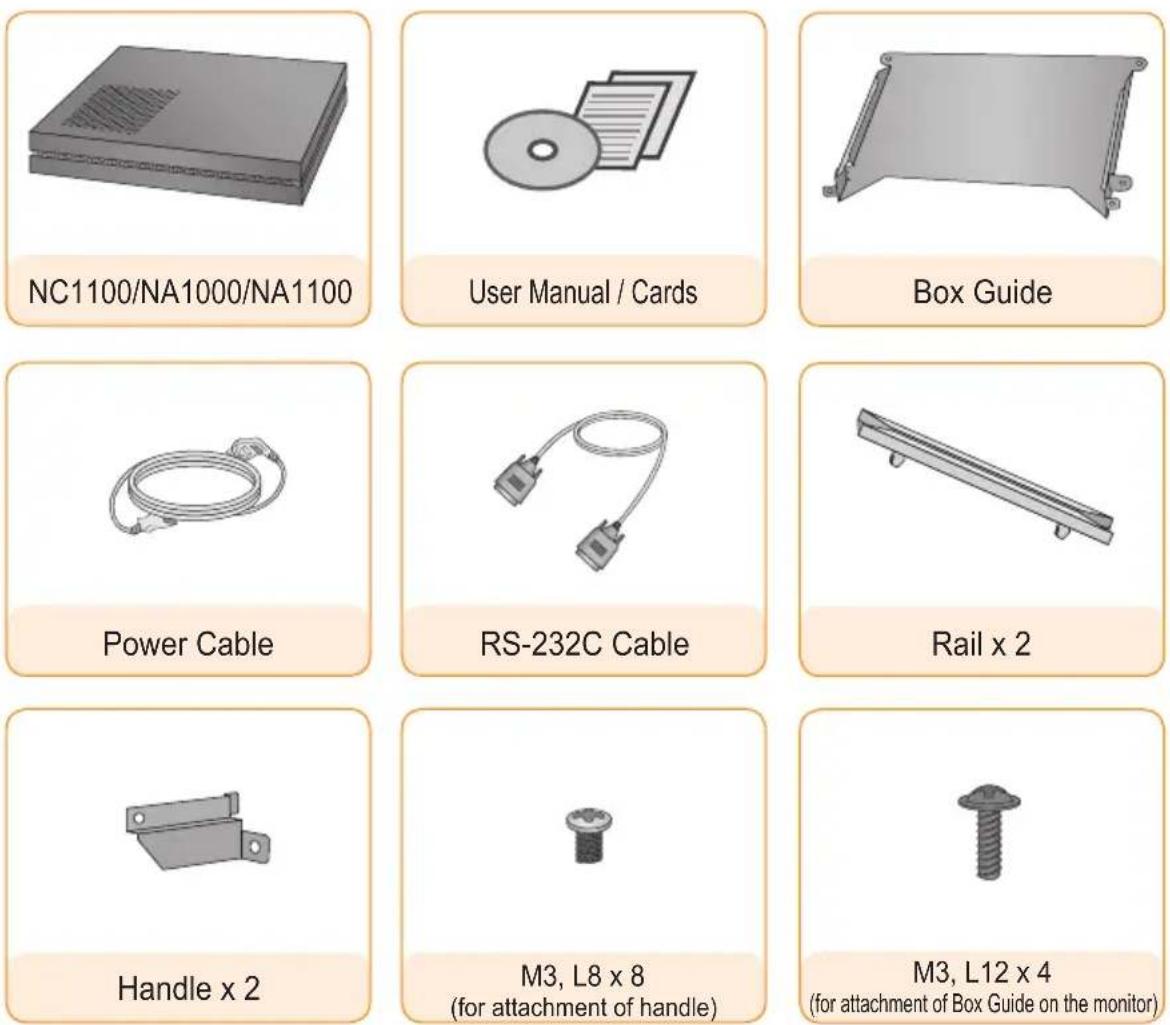
Included in the Box
Basic Components
The NC1000 with the following components. Please check that these components have been included prior to installation.

natural_image
3D rendered image of a rectangular electronic component labeled NC1000 (no other text or symbols visible)
text_image
User Manual / Cards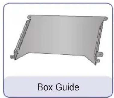
natural_image
Illustration of a 3D rectangular metal frame with support legs, labeled 'Box Guide' below (no other text or symbols)
text_image
Power Cable
natural_image
Illustration of a RS-232C cable with two connectors (no text or symbols on the diagram itself)
natural_image
Simple line drawing of a rail support structure labeled 'Rail x 2' (no other text or symbols)
natural_image
3D rendered mechanical bracket with label 'Handle x 2' below (no other text or symbols)
text_image
M3, L8 x 8 (for attachment of handle)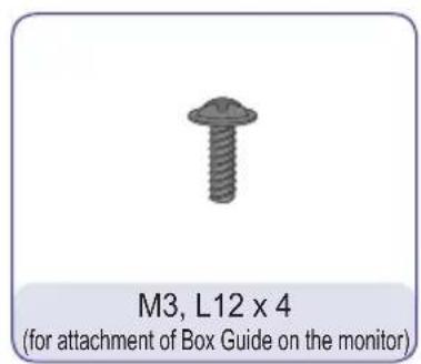
text_image
M3, L12 x 4 (for attachment of Box Guide on the monitor)
Attention
• These illustrations may differ from your product and are subject to change.
Optional Items
The following items are supported by the NC1000, but are not provided with the product.
Please purchase optional items as needed.
- HDMI cable, D-sub cable, LINE-OUT cable, fiber optic cable, LAN cable, mouse, keyboard.
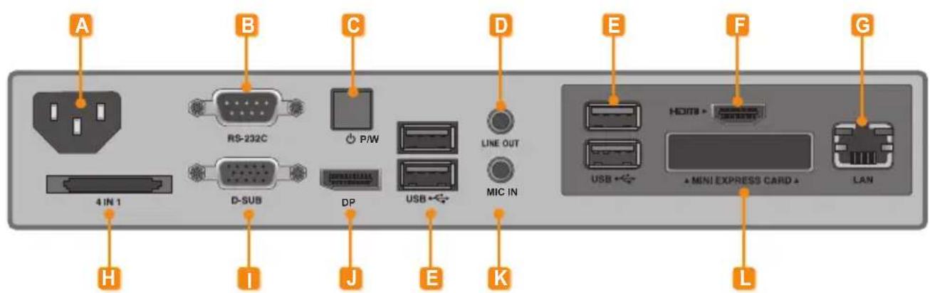
Back Panel
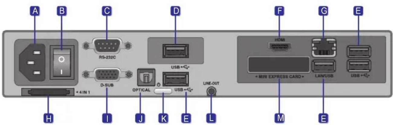
text_image
A B C D F G E H I J K L +4IN 1 RS-232C D-SUB OPTICAL USB← USB← LINE-OUT + MINI EXPRESS CARD→ LAN/USB USB← M ENumber Connection Description
| A | Power Cable In For the power cable. | |
| B | Power Switch Provides power to the NC1000. | |
| C | RS-232C Out For the RS-232C cable. | |
| D | USB Wireless Modem In For a USB-type wireless modem. | |
| E | USB In | For USB-type devices, including memory, hard disk, CD-ROM, key-board, and mouse. |
| F | HDMI Out For an HDMI-compatible monitor. | |
| G | LAN Connector For a LAN cable. | |
| H | 4 IN 1 Multi-Card Slot | Accommodates memory cards for storing video or reading images.Supported cards include Secure Digital (SD), MultiMedia (MMC/MMC4.0), Memory Stick (MS/MS-Pro), and xD Memory Cards. |
| I | D-sub Out For the monitor's RGB video in. | |
| J | OPTICAL Out For an optical cable for digital audio transfer. | |
| K | NC1000 Power Button Turns NC1000 on. | |
| L | LINE-OUT Connector For a LINE-OUT cable for analog audio transfer. | |
| M | PCI MINI EXPRESS Card Slot | Provided for PCI Mini Express Cards. |

Attention
Turn on the power switch (B) and then turn on the power button (K) to power on NC1000.
NC1000
Installation
We recommend you to use the items provided with your NC1000 and follow our instructions for integrating the product with your monitor in order to ensure the correct results.

Attention
The illustrations shown are to guide your integration and may differ from your product.
1 Place the handle into the slots on the side of the product.
natural_image
3D rendering of a server rack with an inset close-up showing internal components (no text or symbols visible)2 Use screws to secure the handle.
natural_image
Diagram of a computer chassis showing internal components and a close-up view of the internal device (no text or symbols present)3 Place the rail in the slots on the side of the product.
natural_image
3D diagram of a server rack with labeled ports and a magnified inset showing internal structure (no text or symbols)
Warning
- Be careful of sharp edges on the rail and the handle.
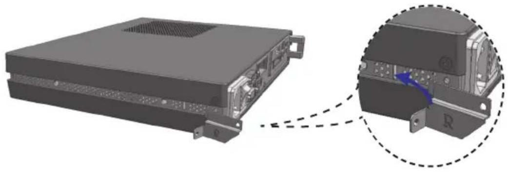
4 As shown below, use screws to secure the Box Guide in the four slots at the back of the monitor.
natural_image
3D rendering of a mechanical or electronic component with mounting holes and a central rectangular block (no visible text or symbols)5 Attach the Box Guide to the rail slots, and press it upward.
natural_image
3D mechanical component with a blue arrow indicating direction, no visible text or symbols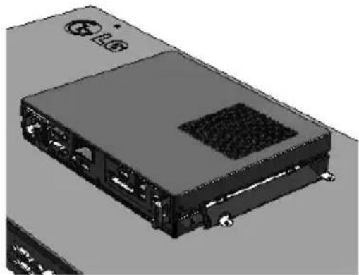
natural_image
3D rendering of a black electronic device with ports and a central grille (no visible text or symbols)6 Use screws to secure the player and the Box Guide as shown below.

natural_image
Diagram showing a device with ports and an inset close-up of its internal structure (no text or symbols visible)In/Out Cable Connection
In order to watch video on a monitor, you need to use a D-sub cable or an HDMI cable to connect the NC1000 to a monitor.

Attention
- D-sub, HDMI, LINE-OUT, OPTICAL, and LAN cables are not included with the NC1000. If the cables were not provided with your monitor, you may need to purchase them separately.
- After cabling is complete, assign the SET ID of the monitor to be connected to NC1000.
- To configure the SET ID, please refer to the owner's manual for your monitor.

Note
When using the SuperSign Manager software:
- The monitor SET ID is a unique number used to identify the monitor. You can choose a number from 1 to 25. The SET ID allows the SuperSign Manager software to identify the monitor.
- In order to directly connect the monitor to NC1000, its SET ID must be set to 1.
- To use SuperSign Manager, the monitor that will be connected to NC1000 must support the LG RS232C protocol. A monitor supporting the LG RS232C protocol can control the monitor functions, such as brightness and sound, using SuperSign Manager.
Connecting a Monitor with D-sub Cable

Attention
- A D-sub cable connection does not include an audio signal. For audio, you need to connect a LINE-OUT or OPTICAL cable.

Note
• D-sub cables are also known as RGB cables.
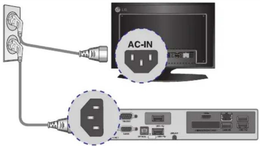
1 Connect the appropriate power cables to a monitor and NC1000 respectively.

text_image
AC-IN2 Connect the D-sub port of NC1000 and RGB-IN port of the monitor with a D-sub cable.
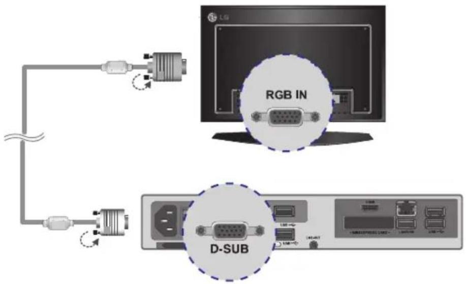
text_image
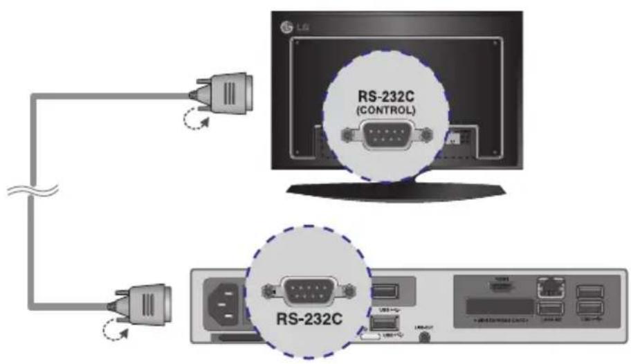
RGB IN D-SUB3 Connect NC1000 (OUT) to the monitor (IN) with an RS-232C cable.

text_image
LG RS-232C (CONTROL) RS-232C USB+0 USB+1 USB+2 USB+3 USB+4 USB+5 USB+6 USB+7 USB+8 USB+9 USB+10 USB+11 USB+12 USB+13 USB+14 USB+15 USB+16 USB+17 USB+18 USB+19 USB+20 USB+21 USB+22 USB+23 USB+24 USB+25 USB+26 USB+27 USB+28 USB+29 USB+30 USB+31 USB+32 USB+33 USB+34 USB+35 USB+36 USB+37 USB+38 USB+39 USB+40 USB+41 USB+42 USB+43 USB+44 USB+45 USB+46 USB+47 USB+48 USB+49 USB+50 USB+51 USB+52 USB+53 USB+54 USB+55 USB+56 USB+57 USB+58 USB+59 USB+60 USB+61 USB+62 USB+63 USB+64 USB+65 USB+66 USB+67 USB+68 USB+69 USB+70 USB+71 USB+72 USB+73 USB+74 USB+75 USB+76 USB+77 USB+78 USB+79 USB+80 USB+81 USB+82 USB+83 USB+84 USB+85 USB+86 USB+87 USB+88 USB+89 USB+90 USB+91 USB+92 USB+93 USB+94 USB+95 USB+96 USB+97 USB+98 USB+99 USB+1004 Connect the NC1000 to the monitor with a LINE-OUT cable.
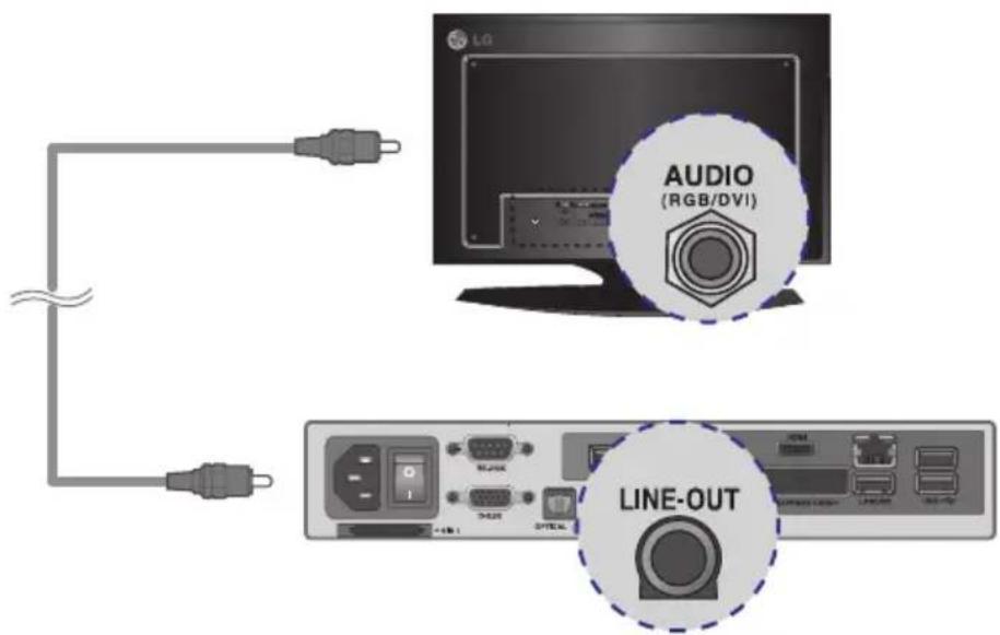
text_image
LG AUDIO (RGB/DVI) LINE-OUT5 Connect a LAN cable to the NC1000.
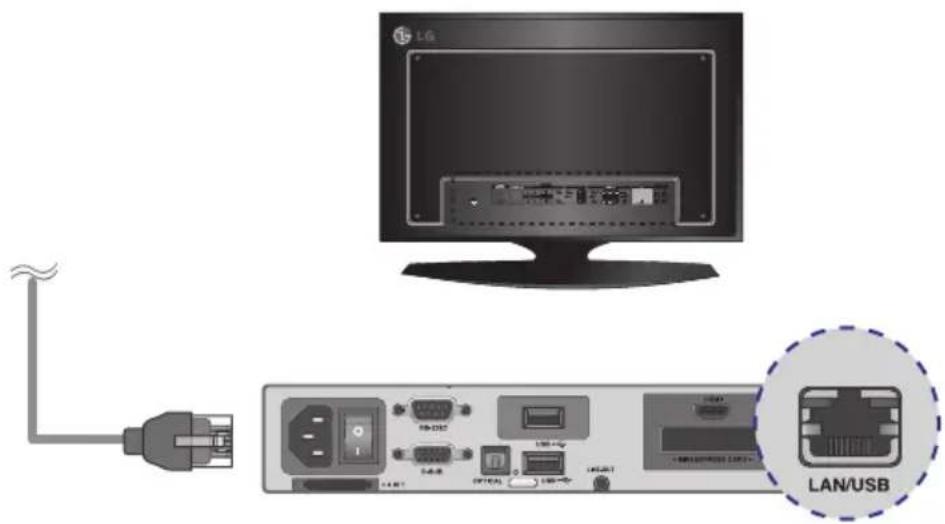
text_image
LG LAN/USBIn/Out Cable Connection
Connecting a Monitor with an HDMI Cable
HDMI connections allow digital video and audio signals to be transferred with one cable.
HDMI cable connections do not require an additional audio in cable.
Attention
- The monitor to connect with NC1000 should have the HDMI in for the HDMI connection.
- To use the HDMI device, you need to activate the HDMI device in Microsoft Windows Embedded Standard, the operating system of the NC1006. connect and disconnect the HDMI audio device, see the Connecting/Disconnecting HDMI Audio Device in Windows section of this document.
1 Connect the appropriate power cables to a monitor and NC1000 respectively.
text_image
AC-IN2 Connect NC1000 to a monitor with an HDMI cable.

text_image
LG HDMI / DVI HDMI3 Connect NC1000 (OUT) to the monitor (IN) with an RS-232C cable.
text_image
RS-232C (CONTROL) RS-232C4 Connect a LAN cable to NC1000.

text_image
LG LAN/USBConnecting/Disconnecting HDMI Audio Device in Windows
Connecting HDMI Audio Device
Move to the desktop of the monitor connected to the NC1000.
| 1 | Click thestartbutton in the lower left of the screen. |
| 2 | Select Start > Control Panel > Sounds and Audio Devices > Audio. |
| 3 | Select Play Sounds > NVIDIA High Definition Audio from the listand click OK. |
Disconnecting HDMI Audio Device
Move to the desktop of the monitor connected to the NC1000.
| 1 | Click thestartbutton in the lower left of the screen. |
| 2 | Select Start > Control Panel > Sounds and Audio Devices > Audio. |
| 3 | Select Play Sounds > Realtek HD Audio output from the list and click OK. |

Attention
- If you do not reset after disconnecting the HDMI cable from the NC1000, the sound will not work.
- In order for the sound to work properly, stop playing the content and restart the NC1000.
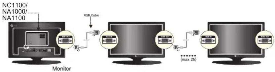
Connection to Multiple Monitors
Each NC1000 can accommodate up to 25 monitors for video playback. (SET ID: 1 to 25)
You can set the tile mode by connecting multiple monitors.
1 Connect the NC1000's D-sub OUT to the D-sub IN of the first monitor, which has SET ID = 1.
2 Connect other monitors with D-sub cables as shown below (IN/OUT separated).
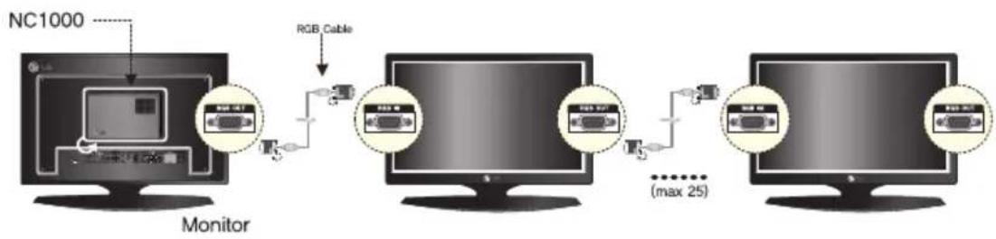
flowchart
graph TD
    A["Monitor"] -->|RGB Cable| B["Computer"]
    B --> C["Computer"]
    C --> D["Computer"]
    D --> E["Computer"]
    style A fill:#f9f,stroke:#333
    style B fill:#ccf,stroke:#333
    style C fill:#cfc,stroke:#333
    style D fill:#fcc,stroke:#333
    style E fill:#ffc,stroke:#333
3 Connect the NC1000's RS-232C OUT to the RS-232C IN of the first monitor, which has SET ID = 1.
4 Connect other monitors with RS-232C cables as shown below (IN/OUT separated).
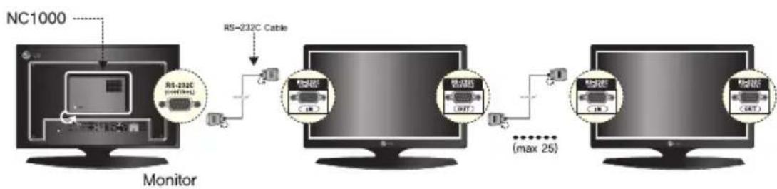
flowchart
graph LR
    A["Monitor"] -->|RS-232C Cable| B["Switch"]
    B --> C["Switch (MAX 25)"]
    C --> D["Switch (MAX 25)"]
    D --> E["Switch (MAX 25)"]
    style A fill:#f9f,stroke:#333
    style B fill:#ccf,stroke:#333
    style C fill:#cfc,stroke:#333
    style D fill:#fcc,stroke:#333
    style E fill:#cff,stroke:#333
Attention
- You may want to purchase additional RS-232C cables to use several monitors together.
- You cannot use multiple monitors with the HDMI cable.
Attention
- Product specifications may change without prior notice to improve performance.
General Specifications
Dimensions 99.8 mm (W) x 183.3 mm (H) x 28.4 mm (D) (only Set)
Weight 0.215 kg (only Set)
CPU Intel ATOM Processor 330 1.6 GHz(Dual Core), FSB 533 MHz
Chip Set Nvidia MCP7A-I ON
Main Memory DDR3 1066 SODIMM type 1 GB, 2 GB
Secondary Storage Device SATA SSD 8 GB, 16 GB, 32 GB
O/S Windows Embedded Standard
Multi I/O port
| Serial Port | N/A |
| USB Port | Hi-Speed USB 2.0 port 480 Mbps rate (x3) |
| LAN Port | Realtek RTL8103E 10/100 Mbps Ethernet controller (NC2000-**A*/**B*) |
| Realtek RTL8111E Gigabit Ethernet controller (NC2000-**P*/**Q*) | |
| VGA / HDMI | Nvidia MCP7A-ION integrated Graphic chipset |
| 4-in-1 Card | N/A |
| PCI Express Card Slot | Supported |
| LINE OUT | N/A |
| SPDIF(Digital Audio Out) | N/A |
Operational Specifications
| Resolution | Maximum Resolution 1920 x 1080 @ 60 Hz | ||||
| Recommended Resolution 1920 x 1080 @ 60 Hz | |||||
| Power | Rated Voltage | 12 V --- 3.5 A | |||
| Operating Condition | Sync (H/V) Video LED | ||||
| Normal Mode On/On Active On | |||||
| Deep Sleep Mode(Set = Off) | Off/Off Off | Off | |||
| Operating Conditions | Operating Conditions | Temperature | 5 °C to 40 °C | Humidity | 10 % to 80 % |
| Storage Conditions | Temperature | -20 °C to 60 °C | Humidity | 5 % to 95 % | |
Included in the Box
Basic Components
The NC2000 consists of the following components. Please check that these components have been included prior to installation.
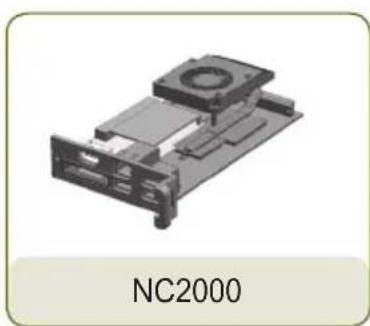
natural_image
3D mechanical component diagram labeled NC2000, showing internal components without any text or symbols on the object itself.
text_image
User Manual / Cards
text_image
screw x 2Attention
- These illustrations may differ from your product and are subject to change.
Attention
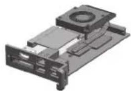
natural_image
3D rendering of a mechanical device with a central circular component and surrounding rectangular components (no visible text or symbols)The NC2000-**A*/**B* model, as shown in the image, is compatible with the following models.
Applicable models: M3204C**A**, M4214C**A**, M4716C**A**
Attention
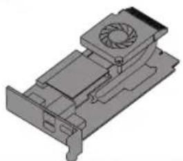
natural_image
3D technical illustration of a mechanical component with a fan and housing (no text or symbols)The NC2000-**P*/**Q* model, as shown in the image, is compatible with the following models.
Applicable models: M3204C**R**, M4214C**R**, M4716C**R**, 32VS10, 42VS10, 47VS10
Attention
Without prior notice, applicable models for NC2000 are subject to change to improve the performance of the product.
Back Panel
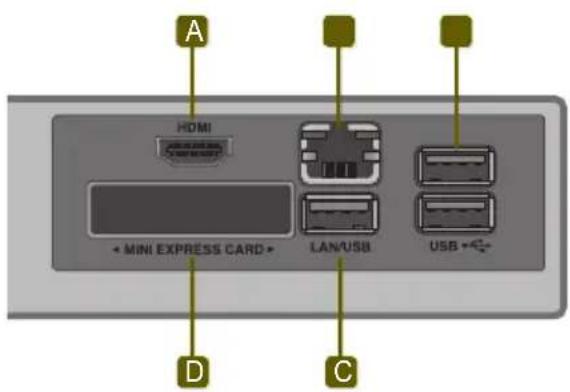
text_image
A HDMI + MINI EXPRESS CARD + LAN/USB USB + D C| Number | Connection | Description |
| A | HDMI Out For an HDMI-compatible monitor. | |
| B | LAN Connector For a LAN cable. | |
| C | USB In | For USB-type devices, including memory, hard disk, CD-ROM, keyboard, and mouse. |
| D | PCI MINI EXPRESS Card Slot Provided for PCI Mini Express Cards. | |
NC2000
Installation
We recommend you to use the items provided with your NC2000 and follow our instructions for integrating the product with your monitor in order to ensure the correct results.

Attention
The illustrations shown are to guide your integration and may differ from your product.
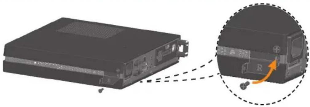
1 Remove the screw and Metal cover.
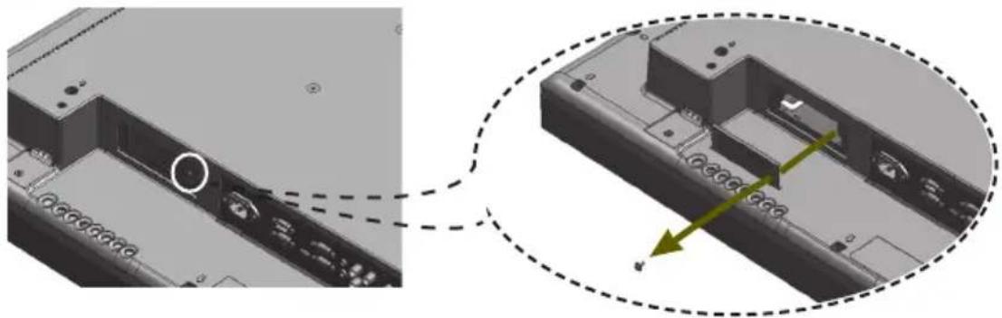
natural_image
3D mechanical assembly diagram showing internal components and a close-up view of a component with arrows indicating motion (no text or symbols)2 Attach the Box Guide to the rail slots, and press it upward.

natural_image
3D mechanical assembly diagram showing a component with a green arrow indicating direction (no text or symbols)
natural_image
3D mechanical assembly diagram showing a component with green arrows indicating motion or force direction (no text or symbols)
Note
If card does not become fully inserted into the insertion direction.
Hit by hand carefully to make fully connected.
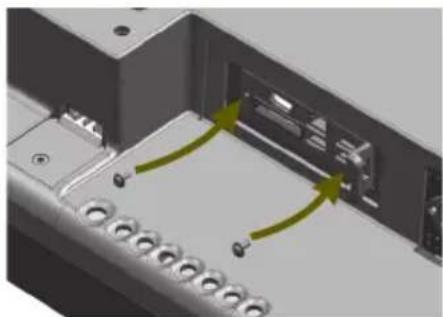
3 Use screws to secure the player and the Box Guide as shown below.
natural_image
3D mechanical assembly diagram showing internal components with green arrows indicating motion or flow (no text or symbols)Specifications
Attention
- Product specifications may change without prior notice to improve performance.
General Specifications
| Dimensions 250 mm (W) x 220 mm (H) x 45 mm (D) (only Set) | |
| Weight SSD 1.590 kg (only Set) | |
| HDD 1860 g (only Set) | |
| CPU NC1100 Intel Celeron Processor P4500 (2M Cache, 1.86 GHz) | |
| NA1000 Intel CoreTM i7-620M Processor (4M Cache, 2.66 GHz) | |
| NA1100 Intel CoreTM i5-520M Processor (3M Cache, 2.40 GHz) | |
| Chip Set Mobile Intel QM57 Express Chipset | |
| Main Memory DDR3 1066 SODIMM type 1 GB, 2 GB | |
| Secondary Storage Device | SATA SSD 8 GB, 16 GB, 32 GB, 64 GB |
| SATA SSD 320 GB | |
| O/S | Microsoft® Windows® Embedded Standard |
| Microsoft® Windows® Embedded Standard 7 E | |
| Microsoft® Windows® Embedded Standard 7 P | |
Multi I/O Port
| Serial Port | One external RS-232 Serial port |
| USB Port | Hi-Speed USB 2.0 port 480 Mbps rate (x4) |
| LAN Port | Intel® 82577 Gigabit Ethernet PHY |
| VGA / HDMI / DP | Intel® HD Graphics Controller |
| 4-in-1 Card Secure Digital (SD) / MultiMedia Card (MMC/MMC4.0) / Memory Stick (MS/MS-Pro) / xD Memory Card | |
| PCI Express Card Slot | Supported |
| LINE OUT | Supported |
| MIC IN Supported | |
Operational Specifications
| Resolution | Maximum Resolution 1920 x 1080 @ 60 HzRecommended Resolution 1920 x 1080 @ 60 Hz | ||||
| Power | Rated Voltage 100-240 V~ 50/60 Hz 1.5 A | ||||
| Operating Condition | Sync (H/V) | Video | LED | ||
| Normal Mode | On/On | Active | On | ||
| Deep Sleep Mode(Set = Off) | Off/Off | Off | Off | ||
| Operating Conditions | Operating Conditions | Temperature | 5 °C to 40 °C | Humidity | 10 % to 80 % |
| Storage Conditions | Temperature | -20 °C to 60 °C | Humidity | 5 % to 95 % | |
Included in the Box
Basic Components
The NC1100/NA1000/NA1100 with the following components. Please check that these components have been included prior to installation.

Attention
• These illustrations may differ from your product and are subject to change.
Optional Items
The following items are supported by the NC1100/NA1000/NA1100, but are not provided with the product. Please purchase optional items as needed.
- HDMI cable, D-sub cable, DP cable, LINE-OUT cable, MIC-IN cable, LAN cable, mouse, keyboard.
Connections
Back Panel
text_image
A B C D E F G 4 IN 1 RS-232C P/W LINE OUT MIC IN USB HDMI MINI EXPRESS CARD LAN 4 IN 1 D-SUB DP USB H I J K LNumber Connection Description
| A | Power Cable In For the power cable. | |
| B | RS-232C Out For the RS-232C cable. | |
| C | Power Button Turns the power on for NC1100/NA1000/NA1100's. | |
| D | LINE-OUT Connector For a LINE-OUT cable for analog audio transfer. | |
| E | USB In | For USB-type devices, including memory, hard disk, CD-ROM, key-board, and mouse. |
| F | HDMI Out For an HDMI-compatible monitor. | |
| G | LAN Connector For a LAN cable. | |
| H | 4 IN 1 Multi-Card Slot | Accommodates memory cards for storing video or reading images. Supported cards include Secure Digital (SD), MultiMedia (MMC/MMC4.0), Memory Stick (MS/MS-Pro), and xD Memory Cards. |
| I | D-sub Out For the monitor's RGB video in. | |
| J | DP Output Port Connects the cable to the DP-supporting monitor. | |
| K | MIC-In Connects the Mic-In cable to transfer analog audio input. | |
| L | PCI MINI EXPRESS Card Slot Provided for PCI Mini Express Cards. | |
Installation
We recommend you to use the items provided with your NC1100/NA1000/NA1100 and follow our instructions for integrating the product with your monitor in order to ensure the correct results.

Attention
The illustrations shown are to guide your integration and may differ from your product.
1 Place the handle into the slots on the side of the product.

natural_image
Illustration of a computer drive chassis with an inset showing a close-up of the internal components (no text or symbols visible)2 Use screws to secure the handle.
natural_image
Illustration of a server rack with an inset close-up showing a device's internal components (no text or symbols)3 Place the rail in the slots on the side of the product.

natural_image
3D diagram of a computer drive showing internal components and a close-up view of the internal structure (no text or symbols)
Warning
- Be careful of sharp edges on the rail and the handle.
4 As shown below, use screws to secure the Box Guide in the four slots at the back of the monitor.
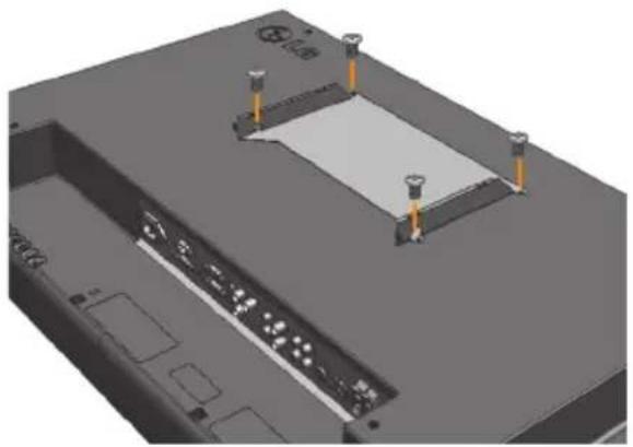
natural_image
3D CAD model of a mechanical assembly with mounting holes and a central rectangular component (no text or symbols visible)5 Attach the Box Guide to the rail slots, and press it upward.
natural_image
3D mechanical component diagram showing a housing and internal structure with an orange arrow indicating motion (no text or symbols)
natural_image
3D rendering of a rectangular electronic device with internal components, placed on a flat surface (no visible text or symbols)6 Use screws to secure the player and the Box Guide as shown below.

natural_image
3D rendering of a device with a highlighted internal component and an orange arrow indicating rotation (no text or symbols)In/Out Cable Connection
To view images on the monitor, you need to connect NC1100/NA1000/NA1100 to the monitor via a D-SUB, HDMI or DP cable.

Attention
- D-SUB, HDMI, DP, LINE-OUT, MIC-IN and LAN cables are not included in the basic components. If cables were not provided with your monitor, you may need to purchase them separately.
- After cabling is complete, assign the SET ID of the monitor to be connected to NA1000/NC1100/NA1100.
- To configure the SET ID, please refer to the owner's manual for your monitor.

Note
When using the SuperSign Manager software:
- The monitor SET ID is a unique number used to identify the monitor. You can choose a number from 1 to 25. The SET ID allows the SuperSign Manager software to identify the monitor.
- In order to directly connect the monitor to NC1100/NA1000/NA1100, its SET ID must be set to 1.
- To use SuperSign Manager, the monitor that will be connected to NC1100/NA1000/NA1100 must support the LG RS232C protocol. A monitor supporting the LG RS232C protocol can control the monitor functions, such as brightness and sound, using SuperSign Manager.
Connecting a Monitor with D-sub Cable

Attention
Audio is not available when only the D-SUB cable is connected to the monitor. A LINE-OUT cable must be connected for audio output to function.

Note
D-sub cables are also known as RGB cables.
1 Connect the appropriate power cables to a monitor and NC1100/NA1000/NA1100 respectively.

text_image
AC IN2 Connect the D-sub port of NC1100/NA1000/NA1100 and RGB-IN port of the monitor with a D-sub cable.

text_image
RGB IN D-SUB3 Connect NC1100/NA1000/NA1100 (OUT) to the monitor (IN) with an RS-232C cable.

text_image
LG RS-232C (CONTROL) RS-232C4 Connect the NC1100/NA1000/NA1100 to the monitor with a LINE-OUT cable.
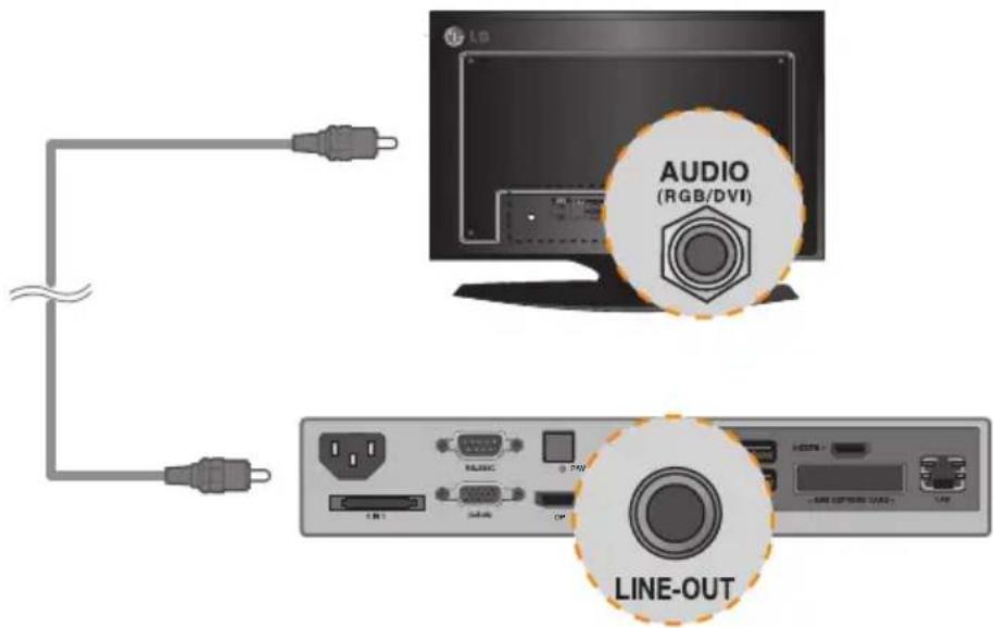
text_image
AUDIO (RGB/DVI) LINE-OUT5 Connect a LAN cable to the NC1100/NA1000/NA1100.
text_image
Diagram showing connection between a computer monitor and an Ethernet device via USB cable, with a close-up of the LAN port.NC1100/NA1000/NA1100
In/Out Cable Connection
Connecting a Monitor with an HDMI Cable
HDMI connections allow digital video and audio signals to be transferred with one cable.
HDMI cable connections do not require an additional audio in cable.
Attention
- The monitor to connect with NC1100/NA1000/NA1100 should have the HDMI in for the HDMI connection.
- To use the HDMI device, you need to activate the HDMI device in Microsoft Windows Embedded Standard, the operating system of the NC1100/NA1000/NA1100. To connect and disconnect the HDMI audio device, see the Connecting/Disconnecting HDMI Audio Device in Windows section of this document.
1 Connect the appropriate power cables to a monitor and NC1100/NA1000/NA1100 respectively.
text_image
LG AC IN USB/USB CPU DC USB HCC USB HCC USB USB USB2 Connect NC1100/NA1000/NA1100 to a monitor with an HDMI cable.
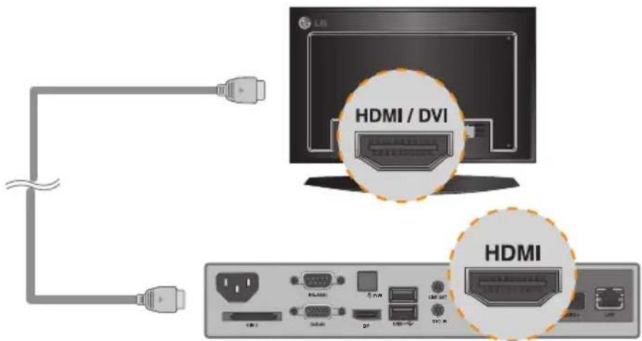
text_image
HDMI / DVI HDMI3 Connect NC1100/NA1000/NA1100 (OUT) to the monitor (IN) with an RS-232C cable.

text_image
LG RS-232C (CONTROL) RS-232C USB port USB port USB port USB port4 Connect a LAN cable to NC1100/NA1000/NA1100.
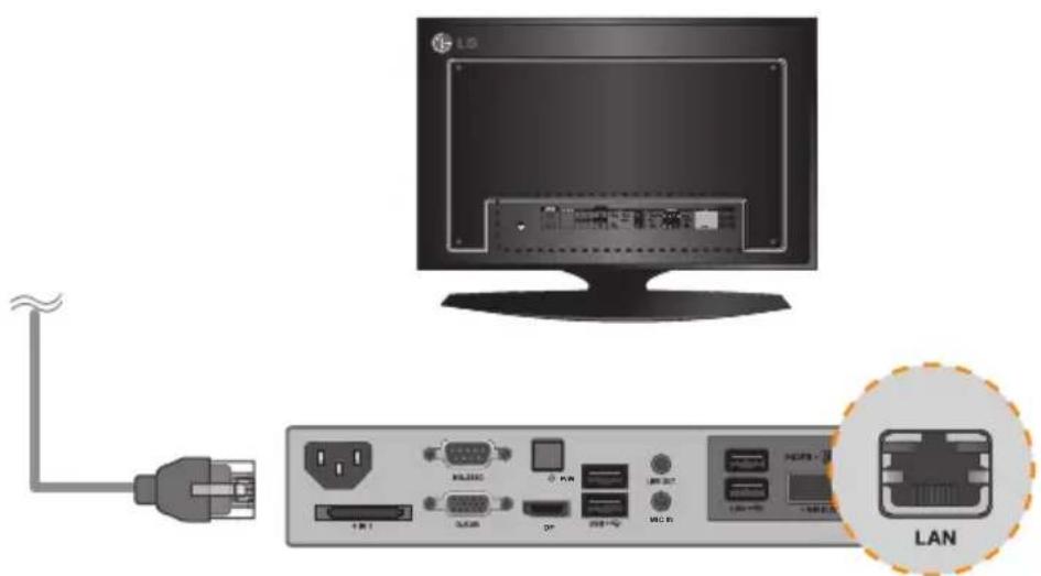
text_image
Diagram showing connection between a computer monitor and an Ethernet port, with a close-up of the LAN device labeled in Chinese.Connecting/Disconnecting HDMI Audio Device in Windows
Connecting HDMI Audio Device
Move to the desktop of the monitor connected to the NC1100/NA1000/NA1100.
1 Click the start button in the lower left of the screen.
2 Select Start > Control Panel > Sounds and Audio Devices > Audio.
3 Select Play Sounds > Intel(R) Display Audio Output 1 from the list and click OK.
Disconnecting HDMI Audio Device
Move to the desktop of the monitor connected to the NC1100/NA1000/NA1100.
1 Click the start button in the lower left of the screen.
2 Select Start > Control Panel > Sounds and Audio Devices > Audio.
3 Select Play Sounds > Realtek HD Audio output from the list and click OK.
Connecting/Disconnecting HDMI Audio Device in Windows Embedded Standard 7 E,P
1 Select Start > Control Panel > Hardware and Sound > Sound.
2 Click the Play tap first. Right-click on the HDMI device or speakers you want and select Set as Default Device then click OK to connect the HDMI audio device or select Disable to disconnect it.
※ In order to change the audio devices, you must restart the computer.
Attention
- If you do not reset after disconnecting the HDMI cable from the NC1100/NA1000/NA1100, the sound will not work.
- In order for the sound to work properly, stop playing the content and restart the NC1100/NA1000/NA1100.
Connecting a Monitor with DP Cable

Attention
To enable DP connection, the monitor that will be connected to NC1100/NA1000/NA1100 must support the DP input port.
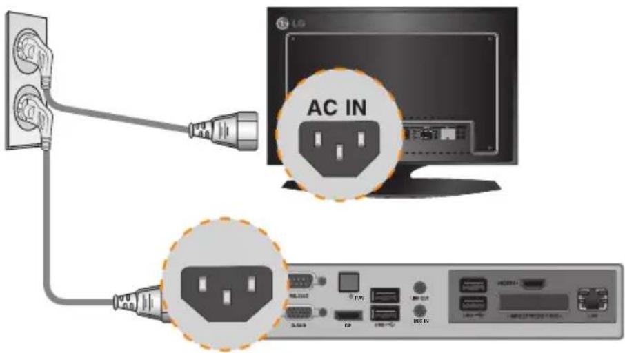
1 Connect the appropriate power cables to a monitor and NC1100/NA1000/NA1100 respectively.
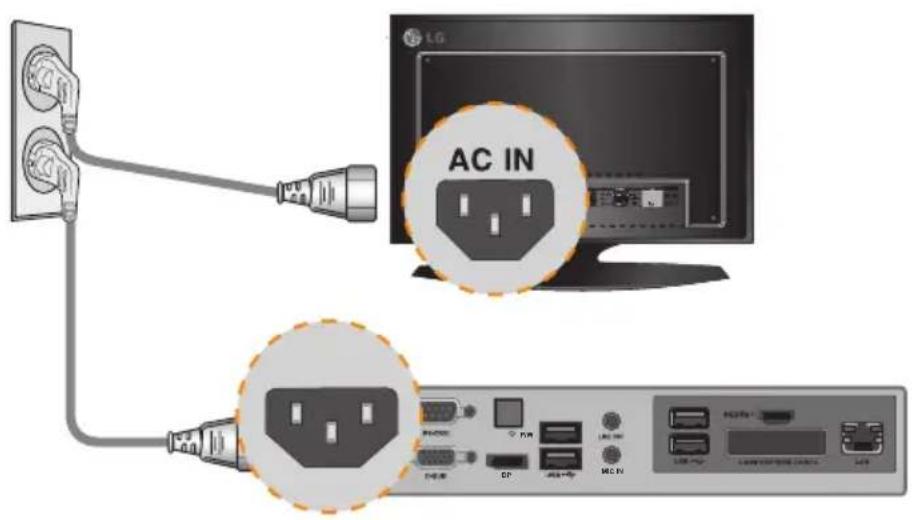
text_image
AC IN1 Connect NC1100/NA1000/NA1100 to the monitor via a DP cable.

text_image
LG DP DP3 Connect NC1100/NA1000/NA1100 (OUT) to the monitor (IN) with an RS-232C cable.

text_image
LG RS-232C (CONTROL) RS-232C4 Connect the NC1100/NA1000/NA1100 to the monitor with a LINE-OUT cable.

text_image
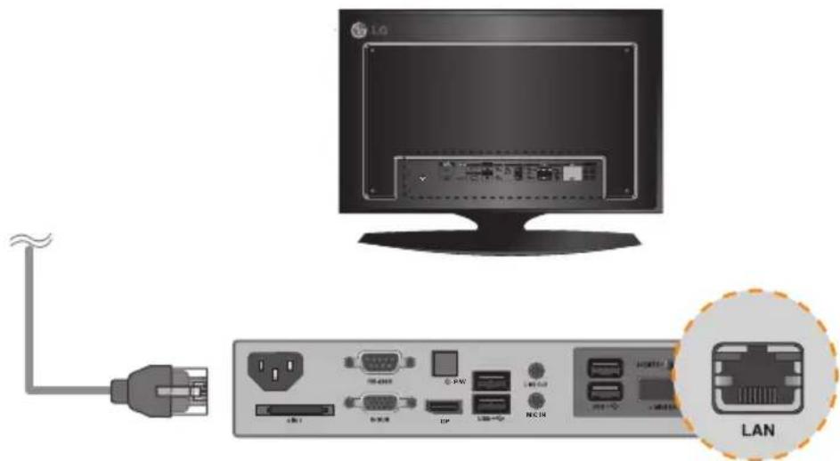
AUDIO (RGB/DVI) LINE-OUT5 Connect a LAN cable to NC1100/NA1000/NA1100.
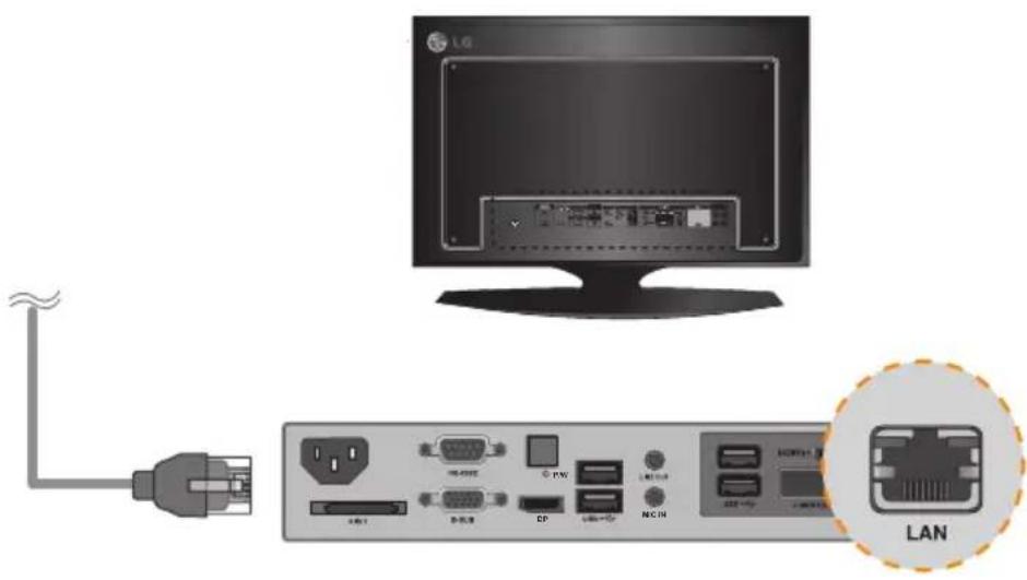
text_image
Diagram showing connection between a computer monitor and an Ethernet LAN device, with labeled ports and connectors.
Attention
- NC1100/NA1000/NA1100 prioritizes video output in the following order: RGB → DP → HDMI. If you connect multiple cables simultaneously and turn the product on, video output is prioritized accordingly.
- When the product is turned on after cable connection or the operating system is completely booted, DP and HDMI video output start operating.
- The product does not support a dual mode where DP can be switched either to HDMI or DVI. It is only for DP output.
- The display port (DP) of the NC1100, NA1000 and NA1100 does not support digital audio output. It is recommended to use it with a line-out cable for analog audio output.
Connection to Multiple Monitors
Each NC1100/NA1000/NA1100 can accommodate up to 25 monitors for video playback. (SET ID: 1 to 25)
1 Connect the NC1100/NA1000/NA1100's D-sub OUT to the D-sub IN of the first monitor, which has SET ID = 1.
2 Connect other monitors with D-sub cables as shown below (IN/OUT separated).
flowchart
graph LR
    A["Monitor"] -->|RGB Cable| B["Switch"]
    B --> C["Switch (max 25)"]
    C --> D["Switch (max 25)"]
    style A fill:#f9f,stroke:#333
    style B fill:#ccf,stroke:#333
    style C fill:#cfc,stroke:#333
    style D fill:#fcc,stroke:#333
3 Connect the NC1100/NA1000/NA1100's RS-232C OUT to the RS-232C IN of the first monitor, which has SET ID = 1.
4 Connect other monitors with RS-232C cables as shown below (IN/OUT separated).

flowchart
graph LR
    A["Monitor"] -->|NC1100/NA1000/NA1100| B["RS-232C Cable"]
    B --> C["Monitor"]
    C --> D["RS-232C (CONTROL)"]
    D --> E["RS-232C (MAX)"]
    E --> F["RS-232C (MAX)"]
    F --> G["RS-232C (MAX)"]
    G --> H["RS-232C (MAX)"]
    H --> I["RS-232C (MAX)"]
    I --> J["RS-232C (MAX)"]
    J --> K["RS-232C (MAX)"]
    K --> L["RS-232C (MAX)"]
    L --> M["RS-232C (MAX)"]
    M --> N["RS-232C (MAX)"]
    N --> O["RS-232C (MAX)"]
    O --> P["RS-232C (MAX)"]
    P --> Q["RS-232C (MAX)"]
    Q --> R["RS-232C (MAX)"]
    R --> S["RS-232C (MAX)"]
    S --> T["RS-232C (MAX)"]
    T --> U["RS-232C (MAX)"]
    U --> V["RS-232C (MAX)"]
    V --> W["RS-232C (MAX)"]
    W --> X["RS-232C (MAX)"]
    X --> Y["RS-232C (MAX)"]
    Y --> Z["RS-232C (MAX)"]
    Z --> AA["RS-232C (MAX)"]
    AA --> AB["RS-232C (MAX)"]
    AB --> AC["RS-232C (MAX)"]
    AC --> AD["RS-232C (MAX)"]
    AD --> AE["RS-232C (MAX)"]
    AE --> AF["RS-232C (MAX)"]
    AF --> AG["RS-232C (MAX)"]
    AG --> AH["RS-232C (MAX)"]
    AH --> AI["RS-232C (MAX)"]
    AI --> AJ["RS-232C (MAX)"]
    AJ --> AK["RS-232C (MAX)"]
    AK --> AL["RS-232C (MAX)"]
    AL --> AM["RS-232C (MAX)"]
    AM --> AN["RS-232C (MAX)"]
    AN --> AO["RS-232C (MAX)"]
    AO --> AP["RS-232C (MAX)"]
    AP --> AQ["RS-232C (MAX)"]
    AQ --> AR["RS-232C (MAX)"]
    AR --> AS["RS-232C (MAX)"]
    AS --> AT["RS-232C (MAX)"]
    AT --> AU["RS-232C (MAX)"]
    AU --> AV["RS-232C (MAX)"]
    AV --> AW["RS-232C (MAX)"]
    AW --> AX["RS-232C (MAX)"]
    AX --> AY["RS-232C (MAX)"]
Attention
- You may want to purchase additional RS-232C cables to use several monitors together.
- You cannot use multiple monitors with the HDMI cable.
Specifications
Attention
- Product specifications may change without prior notice to improve performance.
General Specifications
| Dimensions 99 mm (W) x 179 mm (H) x 28.5 mm (D) (only Set) | |
| Weight 0.288 kg (only Set) | |
| CPU(NC2100) | Intel® Celeron® Processor P4500 (2M Cache, 1.86 GHz) |
| CPU(NA2000) | Intel® CoreTM i7-620M Processor (4M Cache, 2.66 GHz) |
| CPU(NA2100) | Intel® CoreTM i5-520M Processor (3M Cache, 2.40 GHz) |
| Chip Set Mobile Intel® QM57 Express Chipset | |
| Main Memory DDR3 1066 | SODIMM type 1 GB, 2 GB |
| Secondary Storage Device | SATA SSD 8 GB, 16 GB, 32 GB, 64 GB |
| O/S Windows Embedded Standard | |
Multi I/O Port
| Serial Port N/A | |
| USB Port Hi-Speed USB 2.0 port 480 Mbps rate (x2) | |
| LAN Port Intel | ® 82577 Gigabit Ethernet PHY |
| VGA / HDMI / DP Intel | ® HD Graphics Controller |
| 4-in-1 Card N/A | |
| PCI Express Card Slot Supported | |
| LINE OUT N/A | |
| MIC IN N/A | |
Operational Specifications
| Resolution | Maximum Resolution | 1920 x 1080 @ 60 Hz | |||
| Recommended Resolution | 1920 x 1080 @ 60 Hz | ||||
| Power | Rated Voltage | 12 V --- 4.5 A | |||
| Operating Condition | Sync (H/V) | Video | LED | ||
| Normal Mode | On/On | Active | On | ||
| Deep Sleep Mode (Set = Off) | Off/Off | Off | Off | ||
| Operating Conditions | Operating Conditions | Temperature | 5 °C to 40 °C | Humidity | 10 % to 80 % |
| Storage Conditions | Temperature | -20 °C to 60 °C | Humidity | 5 % to 95 % | |
Included in the Box
Basic Components
The NC2100/NA2000/NA2100 consists of the following components. Please check that these components have been included prior to installation.
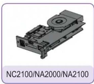
natural_image
3D mechanical component diagram with no visible text or symbols on the part itself
text_image
User Manual / Cards
natural_image
Simple illustration of a screw with a central screw head and label 'screw x 2' below (no other text or symbols)
Attention
These illustrations may differ from your product and are subject to change.

Attention
The NC2100/NA2000/NA2100 model is compatible with the following models. Applicable models: 32VS10, 42VS10, 47VS10

Attention
Without prior notice, applicable models for NC2100/NA2000/NA2100 are subject to change to improve the performance of the product.
Back Panel
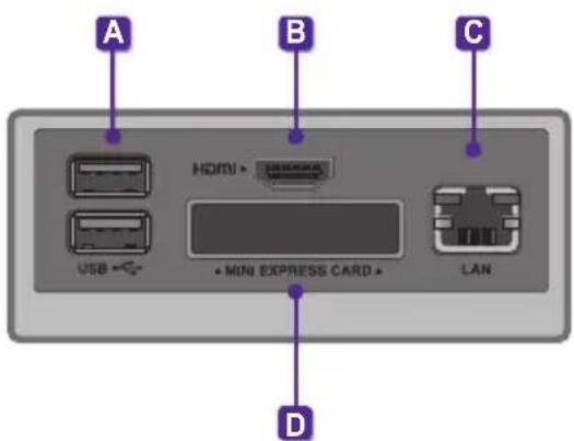
text_image
A B C HDMI • USB • • MINI EXPRESS CARD • LAN D| Number | Connection | Description |
| A | USB In | For USB-type devices, including memory, hard disk, CD-ROM, keyboard, and mouse. |
| B | HDMI Out For an HDMI-compatible monitor. | |
| C | LAN Connector For a LAN cable. | |
| D | PCI MINI EXPRESS Card Slot Provided for PCI Mini Express Cards. | |
Installation
We recommend you to use the items provided with your NC2100/NA2000/NA2100 and follow our instructions for integrating the product with your monitor in order to ensure the correct results.

Attention
The illustrations shown are to guide your integration and may differ from your product.
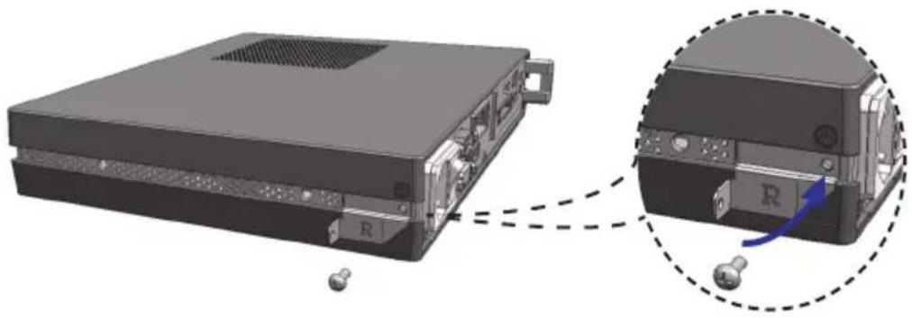
1 Remove the screw and Metal cover.

natural_image
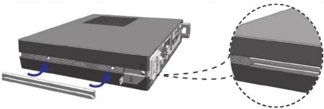
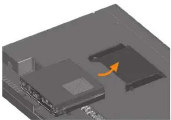
3D mechanical component diagram showing internal structure with highlighted section (no text or symbols)2 Attach the Box Guide to the rail slots, and press it upward.
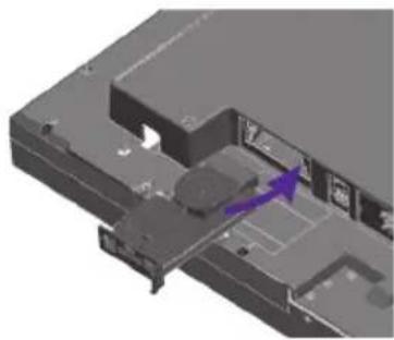
natural_image
3D mechanical component diagram showing internal structure with purple arrow indicating direction (no text or symbols)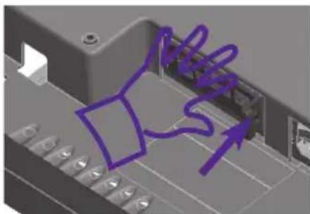
natural_image
3D mechanical component with purple arrows indicating motion or force (no text or symbols)
Note
If card does not become fully inserted into the insertion direction.
Hit by hand carefully to make fully connected.
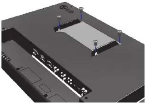
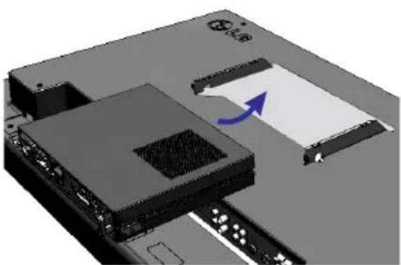
3 Use screws to secure the player and the Box Guide as shown below.

natural_image
3D mechanical assembly diagram showing internal components with purple arrows indicating motion or movement (no text or symbols)Appendix
Limitations of Microsoft Windows Embedded Standard
The following are potential errors that may occur due to internal limitations of Microsoft Windows Embedded Standard, which is the OS of SuperSign Player.
- If you press Alt + Enter on the DOS window, text other than English may be shown corrupted.
- If you use Save As function in the Print window, the menu window name will be displayed in English.
- When you move to sub-menu items such as Control Panel, some of the items, such as hyper terminal, country and language setting, will be written in English.
Frequently Asked Questions (FAQs)
| Question Answer | |
| Where can I download the driver file? | You can obtain the file from the SuperSign Support website (http://www.lgsupersign.com). |
| The Express Card does not work. What should I do? | For NC1000/NC2000, insert the Express Card with the top side facing upward. (See Figure 1)For NC1100/NA1000/NA1100/NC2100/NA2000/NA2100, insert the Express Card with the bottom side facing upward. (See Figure 2) < Figure 1 >< Figure 2 > < Figure 1 >< Figure 2 > |
| Where can I get a vaccine program? | This media player comes packaged with the Windows program only. Please purchase a vaccine program separately for use. |

text_image
LG Life's GoodMake sure to read the Important Precautions before using the product.
Keep the User's Guide(CD) in an accessible place for furture reference.
The model and serial number of the SET is located on the back and one side of the SET.
Record it below should you ever need service.
MODEL
SERIAL
WARNING - This is a class A product. In a domestic environment this product may cause radio interference in which case the user may be required to take adequate measures.
Temporary noise is normal when powering ON or OFF this device.