
IntelliSHOT - Video Conferencing System Vaddio - Free user manual and instructions
Find the device manual for free IntelliSHOT Vaddio in PDF.

| Product Type | Auto-Tracking PTZ Camera for Video Conferencing |
| Dimensions | Approximately 7.5 x 5.0 x 5.0 inches (19.0 x 12.7 x 12.7 cm) without mount |
| Weight | Approximately 2.5 lbs (1.13 kg) |
| Power Supply | PoE+ (Power over Ethernet Plus) via mid-span injector |
| Optical Zoom | 30x |
| Horizontal Field of View | 70.2° |
| Video Outputs | HDMI, USB 3.0 (UVC/UAC), H.264 IP streaming (RTSP or RTMP) |
| Audio | Integrated echo-canceling phased microphone array, audio line in/out |
| Autoframing Technology | IntelliFrame™ motion-based automatic framing without facial recognition |
| Control Interfaces | Web interface, RF remote (pairing required), Telnet API, Vaddio Device Controller |
| Maximum Video Resolution | 1080p/60 via HDMI; 1080p/30 via USB and IP streaming |
| Mounting | Wall mount included; supports inverted installation with Image Flip setting |
| Operating Temperature | 32°F to 104°F (0°C to 40°C) |
| Storage Temperature | 32°F to 104°F (0°C to 40°C) |
| Cleaning | Wipe with soft, lint-free cloth; use lens cleaner for optics |
| Safety | Indoor use only; do not expose to liquids or extreme humidity |
| Spare Parts & Repairability | No user-serviceable parts; contact Vaddio support for service |
Frequently Asked Questions - IntelliSHOT Vaddio
User questions about IntelliSHOT Vaddio
0 question about this device. Answer the ones you know or ask your own.
Ask a new question about this device
Download the instructions for your Video Conferencing System in PDF format for free! Find your manual IntelliSHOT - Vaddio and take your electronic device back in hand. On this page are published all the documents necessary for the use of your device. IntelliSHOT by Vaddio.
USER MANUAL IntelliSHOT Vaddio
natural_image
Three VADDIO camera modules shown from different angles against a blue background (no text or symbols on the devices themselves)Complete Manual for the
IntelliSHOT
Auto-Tracking Camera
Document 411-0053-30 Rev B
August 2021
Contents
Overview 1
What's in this Guide 1
Features 1
A Quick Look at the Camera 2
Front of the Camera 2
Connector Panel 3
Installation 4
Don't Void Your Warranty! 4
Before You Install the Camera 4
Cabling Notes 4
Pre-Installation Functional Check 5
Getting the Camera's IP Address 5
If the Camera Is At 169.254.1.1 6
Status Lights 6
Installing the Wall Mount 6
Basic Connections
Installing the Camera and Connecting Power 7
About Inverted Installation 7
Initial Device Set-Up 8
Browser Support 8
Initial Device Set-up Process Overview 8
Initial Device Set-Up Using the Vaddio Device Controller 8
Initial Device Set-Up Using the Vaddio Deployment Tool 9
Manual Access and Initial Device Set-Up 10
Initial Access to the Web Interface 10
Completing the Initial Device Set-up 10
System Administration 11
Configuring Access and Other Security Settings 11
Configuring the Camera for Your Network 12
Configuring the Device with a Static IP Address.... 12
Changing the Camera's Hostname 13
Specifying Time Zone and NTP Server 13
Adding Room Information to the Camera's Web Interface 13
Configuring Camera Behavior 14
Fine-Tuning Autoframing Behavior 14
How It Works: Digital Pan/Tilt/Zoom 14
How It Works: Autoframing 15
Basic Autoframing Adjustments 16
Masking Unwanted Motion 17
Advanced Autoframing Adjustments 18
Autoframing Adjustment Quick Reference 19
Managing Audio 20
Other Audio Settings and Adjustments 20
About Echo Cancellation 21
Configuring Streaming Behavior 22
Viewing the USB Stream 22
Configuring USB Streaming.22
Enabling or Disabling IP Streaming 23
Viewing the IP Stream (RTSP) 23
RTSP Streaming Protocol and URL 24
Setting up IP Streaming in Easy Mode 25
Customizing IP Streaming Settings 25
Configuring RTMP Streaming 26
Changing MTU 26
Configuring Manual Mode Behaviors 27
Setting the Home Position and Other Preset Shots 27.
Renaming Presets and Custom CCU Scenes 28
Speed Adjustments 28
Setting the Direction for Camera Movements 28
Adjusting Color, Lighting, and Image Quality Settings 29
Lighting and Image Quality Quick Reference 30
Color Adjustment Quick Reference 31
Saving Color and Lighting Settings 31
Adjusting the Focus 32
Additional Camera Settings 33
Operating the Camera 34
Operating the Camera from the Web Interface 34
Muting Audio and Video 35
Managing the Camera Ready State 35
Moving the Camera 35
Zooming In or Out 35
Moving the Camera to a Preset Position 35
Operating the Camera with the RF Remote 36
Installing the Batteries 36
Pairing the Remote to the Camera 36
RF Remote Quick Reference 37
Other Things to Know About the Remote 37
Unpairing the Remote 38
System Maintenance 39
Saving (Exporting) or Restoring (Importing) a Configuration 39
Installing a Firmware Update 40
Rebooting the Camera 40
Contacting Vaddio Technical Support and Viewing Diagnostic Logs 41
Telnet Serial Command API 42
Requirements 42
Usage Notes 42
Getting More Information..42
Typographical Conventions 42
Autoframer Commands 43
autoframer enabled 43
autoframer paused 44
autoframer default-wide 44
camera optical-zoom 45
autoframer buffer-zone 45
autoframer shot-margin 46
autoframer sensitivity 46
autoframer responsiveness 47
autoframer initial-persistence 47
autoframer persistence 48
autoframer max-electronic-zoom 48
autoframer max-speed 49
autoframer noise-threshold 49
autoframer tri-sync-motion 50
autoframer history 50
autoframer forced-wait-time 51
Camera and Video Management Commands 52
camera home 52
camera pan 53
camera tilt 54
camera zoom 55
camera ptz-position 56
camera preset 57
camera focus 58
camera ccu scene 58
camera ccu get 59
camera ccu set 60
camera led 60
video mute 61
camera standby 61
Audio Commands 62
audio volume 62
audio mute 63
audio echo-cancel 64
Network and Communication Commands 65
network settings get 65
streaming ip enable 65
streaming settings get 66
Maintenance and Troubleshooting Commands 67
version 67
network ping 67
system reboot 68
system factory-reset 68
Telnet Information and Session Management Commands 69
history 69
help 69
exit 69
Troubleshooting and Care 70
Power and Control 70
Video and Streaming 71
Audio 71
Status Lights 72
Restoring Default Camera Settings 72
Operation, Storage, and Care 73
Glossary 74
Photo Credits 78
Index 79
Overview
This guide covers:
IntelliSHOT ^® auto-tracking camera:
■ North America – 999-21100-000 (black); 999-21100-000W (white)
■ Europe and UK – 999-21100-001 (black); 999-21100-001W (white)
■ Australia and New Zealand – 999-21100-009 (black); 999-21100-009W (white)

natural_image
Exterior view of a VADDIO camera module (no text or symbols visible on body)What's in this Guide
This guide covers
■ Physical features
■ Installation
■ Initial set-up and system administration
■ Performance/behavior configuration
■ System maintenance
Operation
■ Telnet API reference
■ Troubleshooting
For your convenience, the information you need to install this product is also available in the smaller, stand-alone Installation Guide for the IntelliSHOT Auto-Tracking Camera.
Features
■ Integrated camera and audio system, ideal for small to medium conference rooms
- IntelliFrame™ intelligent framing algorithm keeps participants in view reliably, without facial recognition
■ 30x zoom, horizontal field of view of 70.2°
■ Simultaneous HDMI, uncompressed USB 3.0 and H.264 IP streaming (RTSP or RTMP)
■ Up to 1080p/30 video; up to 1080p/60 on HDMI output
■ Integrated phased microphone array
■ Audio line in and line out
■ Universal Video Class (UVC) and Universal Audio Class (UAC) drivers supported in Windows macOS ^® , and Linux operating systems, compatible with most UC conferencing applications
■ Integration-ready Telnet control
■ Full administrative control via web interface; manage the camera remotely while monitoring the stream separately
■ Presenter-friendly RF remote control
A Quick Look at the Camera
This section covers the physical features of the camera.
Front of the Camera
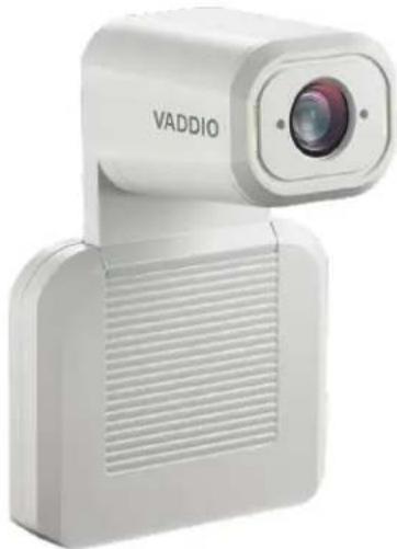
The camera is available in black or white.
natural_image
White VADDIO camera with lens and ventilation grille (no text or symbols visible on body)Camera and zoom lens - Up to 30x zoom.
Integrated microphone - No external microphone needed in typical installations. Echo-canceling microphone picks up the voices of participants up to 10 ft. (3 m) away.
Status lights – The illuminated trim detail on the camera's face indicates the camera's current state. The status lights can be turned off in the administrative web interface.
Pivoting head - Manually tilt the head as needed.
Note
By default, the camera's status lights are active during normal operation; however, they can be configured to remain off when the camera is powered up. The camera may be sending video lights are off.
Connector Panel
The connectors are on the underside of the camera.

natural_image
Front view of a white electronic device with ports and connectors (no visible text or symbols)PoE+ – RJ-45 connector. Connect to the network and to power via the Power and Data Out port of the mid-span PoE+ power injector. Provides power and network access for IP streaming and camera control via web interface or Telnet.
USB 3.0 – USB Type B connector. Connect to a computer for use with soft conferencing applications.
Provides uncompressed USB 3.0 stream.
HDMI output – HDMI video and audio output connector.
IP button – Press to display the camera's IP address on video outputs.
Audio input – Line level balanced audio for an external microphone or other audio source.
Audio output – Line level balanced audio output to amplified speaker or other audio infrastructure.
Installation
This section covers:
■ Selecting the location for the camera
■ Verifying that the camera is ready to install
■ Installing the mount
■ Connection diagrams
■ Mounting the camera
And a required safety note here:
Note
PoE type networks connected to this equipment are for intra-building use only and should not be connected to lines that run outside of the building in which this product is located.
Don't Void Your Warranty!
Caution
This product is for indoor use. Do not install it outdoors or in a humid environment without the protective enclosure. Do not allow it to come into contact with any liquid.
Do not install or operate this product if it has been dropped, damaged, or exposed to liquids. These things happen, return it to Vaddio for safety and functional testing.
Before You Install the Camera
Prepare for a successful installation:
- Consider camera viewing angles, lighting conditions, line-of-sight obstructions, and in-wall obstructions where the camera is to be mounted.
■ Ensure that the camera points away from the ceiling and lights. The camera will not perform well if it is pointed toward a light source such as a light fixture or window.
■ Mounting the camera at eye level is best. If this is not feasible, mounting the camera above eye level typically produces a better experience than mounting it below eye level.
■ If you make cables for this installation, check them for continuity.
■ Be sure you can identify all cables correctly.
■ Talk to the network administrator. If installing the camera in a non-DHCP network (one that does not automatically assign IP addresses), you will need to configure the camera with a static IP address as directed by the network administrator.
Cabling Notes
Use Cat-5e or better cable. Use shielded cabling if the cables will be coiled, run tightly with other cables, or routed near sources of electromagnetic interference such as power lines or fluorescent light fixtures. We recommend using high-quality connectors and a high-quality crimping tool.
Caution
Do not use pass-through RJ-45 connectors when making cables for this product. Poorly crimped connectors of this type can cause intermittent connections and degraded signal quality. They can also damage the connectors on the product, which will void your warranty.
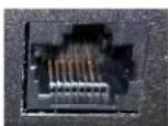
Intact – will make reliable contact with cable connector

Damaged – Bent contact fingers will NOT make reliable contact with cable connector
Pre-Installation Functional Check
If you're installing the camera where it's hard to reach, you may want to verify functionality before you install it.
- Connect the camera in its minimum functional configuration.

flowchart
graph TD
    A["Client"] --> B["Server"]
    B --> C["Network"]
    C --> D["Cat-5e or better"]
    D --> E["Device"]
    E --> F["HDMI"]
    F --> G["Video Group Meeting"]
    style A fill:#f9f,stroke:#333
    style B fill:#ccf,stroke:#333
    style C fill:#cfc,stroke:#333
    style D fill:#fcc,stroke:#333
    style E fill:#cff,stroke:#333
    style F fill:#ffc,stroke:#333
    style G fill:#cfc,stroke:#333
- Connect power. The camera's status light turns white. If an HDMI display is connected, video is available.
- If not using an HDMI display: Connect the camera's USB port to your computer, then open a media player and verify that you can select the camera as the USB video capture device. These screen shots show how to access a camera's USB stream using VLC Media Player. In this example, the capture device is a different camera.


If the camera turns on and sends video, continue with the installation.
Getting the Camera's IP Address
You will need the camera's IP address if you do not use the Vaddio Device Controller or Vaddio Deployment Tool to access its web interface.
Briefly press the IP button on the connector panel. This displays the camera's IP address and MAC address on the video outputs. Press the button again to dismiss the information.
If the Camera Is At 169.254.1.1
This is the camera's default IP address. This means one of these things:
■ The camera's PoE+ power injector is not connected to the network, OR
■ The network does not automatically assign IP addresses.
If the camera does not receive an IP address when connected to the network, you will need to configure the camera for the network after you have done the initial device set-up.
To communicate directly with the camera for initial device set-up and network configuration, you will need to connect a cable from your computer's network port to the DATA IN port on the PoE+ power injector.
Status Lights
The lights in the camera's head indicate its current state.
■ Purple – Initializing
■ White – Active
■ Red – Audio is muted
■ Blinking red – Video is muted
■ Yellow – Firmware update is in progress
■ Blinking cyan – Remote pairing mode
■ Blinking blue – Pairing error
Caution
Do not remove power or reset the camera while the status lights are yellow, showing a firmware progress. Interrupting a firmware update can make the camera unusable.
Note
By default, the camera's status lights are active during normal operation; however, they can be configured to remain off when the camera is powered up. The camera may be sending video lights are off.
Installing the Wall Mount
The camera is shipped with a wall mount. Other mounting options are available as well. Contact us if you don't have the camera mount you need.
You can install the camera wall mount to a display mount or directly to drywall. If you mount it to drywall, use wall anchors.
Basic Connections
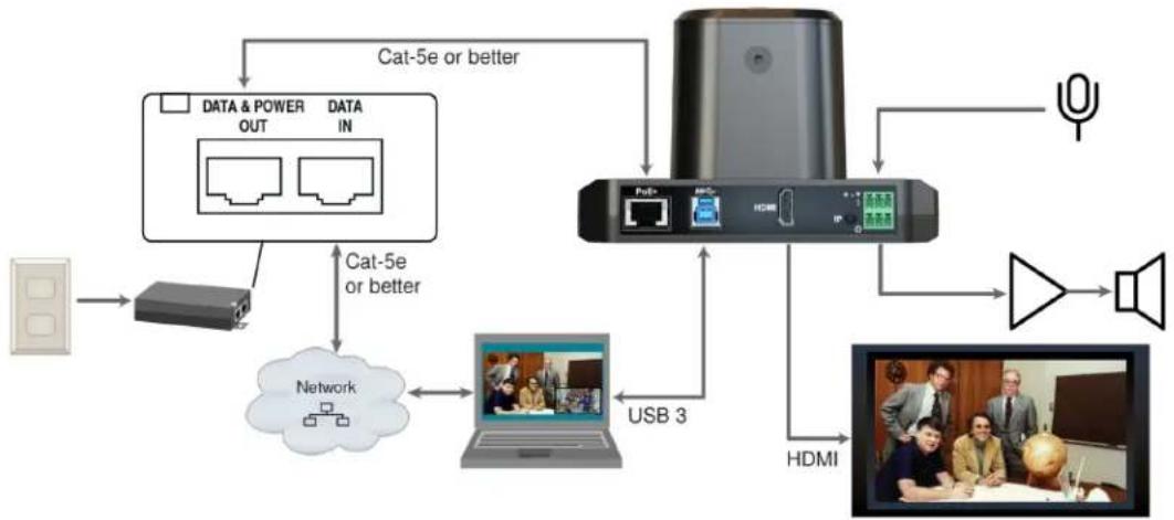
Here is an example of how the camera might be set up in a medium-size conference room. In this setup, a PC uses a unified communications conferencing application to manage the camera and connected microphones and speaker.
flowchart
graph TD
    A["Power"] --> B["Router"]
    B --> C["Network"]
    C --> D["Laptop"]
    D --> E["USB 3"]
    E --> F["Device"]
    F --> G["HDMI"]
    G --> H["Speaker"]
    H --> I["Radio"]
    I --> J["Satellite"]
    J --> K["Satellite"]
    K --> L["Satellite"]
    L --> M["Satellite"]
    M --> N["Satellite"]
    N --> O["Satellite"]
    O --> P["Satellite"]
    P --> Q["Satellite"]
    Q --> R["Satellite"]
    R --> S["Satellite"]
    S --> T["Satellite"]
    T --> U["Satellite"]
    U --> V["Satellite"]
    V --> W["Satellite"]
    W --> X["Satellite"]
    X --> Y["Satellite"]
    Y --> Z["Satellite"]
    Z --> AA["Satellite"]
    AA --> AB["Satellite"]
    AB --> AC["Satellite"]
    AC --> AD["Satellite"]
    AD --> AE["Satellite"]
    AE --> AF["Satellite"]
    AF --> AG["Satellite"]
    AG --> AH["Satellite"]
    AH --> AI["Satellite"]
    AI --> AJ["Satellite"]
    AJ --> AK["Satellite"]
    AK --> AL["Satellite"]
    AL --> AM["Satellite"]
    AM --> AN["Satellite"]
    AN --> AO["Satellite"]
    AO --> AP["Satellite"]
    AP --> AQ["Satellite"]
    AQ --> AR["Satellite"]
    AR --> AS["Satellite"]
    AS --> AT["Satellite"]
    AT --> AU["Satellite"]
    AU --> AV["Satellite"]
    AV --> AW["Satellite"]
    AW --> AX["Satellite"]
    AX --> AY["Satellite"]
    AY --> AZ["Satellite"]
    AZ --> BA["Satellite"]
    BA --> BB["Satellite"]
    BB --> BC["Satellite"]
    BC --> BD["Satellite"]
    BD --> BE["Satellite"]
    BE --> BF["Satellite"]
    BF --> BG["Satellite"]
    BG --> BH["Satellite"]
    BH --> BI["Satellite"]
    BI --> BJ["Satellite"]
    BJ --> BK["Satellite"]
    BK --> BL["Satellite"]
    BL --> BM["Satellite"]
    BM --> BN["Satellite"]
    BN --> BO["Satellite"]
    BO --> BP["Satellite"]
    BP --> BQ["Satellite"]
    BQ --> BR["Satellite"]
    BR --> BS["Satellite"]
    BS --> BT["Satellite"]
    BT --> BU["Satellite"]
    BU --> BV["Satellite"]
    BV --> BW["Satellite"]
Pro Tip
Label all cables at both ends.
Installing the Camera and Connecting Power
Caution
Check your cables. Connecting a cable to the wrong port or using the wrong pin-out can result equipment damage and will void the warranty.
- Connect all required cables to the camera.
- Slide the camera into the mount.
- Secure the cable cover to the mount.
- Connect the mid-span power injector to mains power.

About Inverted Installation
If you use an inverted mount, you will need to select the camera's Image Flip setting when configuring behavior and performance. Image Flip orients the video image correctly and sets the camera to respond appropriately to tilt commands. See Additional Camera Settings for more information.
Initial Device Set-Up
Vaddio cameras have a web interface for initial device set-up, administrative control, and operation.
When any Vaddio product is shipped from the factory, the admin password is not set and the administrative controls are not available. You will need to access the web interface and set the admin password. Then you will be able to access to the system administration tasks to define how the device behaves as an element of your network. This is also true after restoring factory defaults.
Because this process is the same for all Vaddio cameras, screen shots in this section may show different products.
Browser Support
We have tested this product with these web browsers:
Chrome®
■ Firefox®
■ Microsoft® Edge and Internet Explorer®
Safari®
We test using the browser version available from the vendor at that time. Other browsers (including older versions of the ones on this list) are likely to work also.
Initial Device Set-up Process Overview
The details of initial device set-up and system administration differ somewhat, depending on which method you use.
- Access the web interface from a Vaddio Device Controller – The touch-panel automatically scans the subnet to locate Vaddio devices. Select the desired device and exit to the device's web interface to complete the initial device set-up.
- Locate and set up the camera using the Vaddio Deployment Tool – Available as a free download at https://info.legrandav.com/VaddioDeploymentTool. The tool scans the network for Vaddio devices, identifies all devices that are not set up, provides the controls to complete the initial device set-up, and provides links to each device's web interface.
- Access the web interface directly – The classic method. Discover the camera's IP address and browse to its web interface.
Initial Device Set-Up Using the Vaddio Device Controller
The Vaddio Device Controller is a stand-alone tablet for working with Vaddio products.
To complete the initial device set-up with the Vaddio Device Controller:
- Connect the touch-panel to the network on the same subnet as the products you need to work with - for example, connect both to the same PoE+ switch.
- Go to the touch-panel's Configuration page (gear icon) and select Scan.
-
Locate the device you need to work with, and select Use.
If the Vaddio Device Controller does not find the camera, verify that the Vaddio Device Controller and camera are connected to the same subnet. -
Select Exit to leave the Configuration page and open the device's web interface.
Note
The first time you access a device at a specific IP address, the Vaddio Device Controller's s may remain blank for 20 seconds or more.
- Set the admin password.
Initial Device Set-Up Using the Vaddio Deployment Tool
The Vaddio Deployment Tool provides an option to do the initial device set-up for unprovisioned devices, and provides a shortcut to each device's web interface for system administration. This tool is available as a free download at https://info.legrandav.com/VaddioDeploymentTool.
Note
Be sure you have the current version of the Vaddio Deployment Tool. If it notifies you that an available, install the update. This ensures that you have access to the full capabilities of the tool versions may not recognize the newest products.
To complete the initial device set-up with the Vaddio Deployment Tool:
- Power up the camera and other devices if you have not done so already.
- On the Find Devices page, select Scan. If the scan does not locate the devices you need to set up, your computer may be on a different subnet. Return to the Find Devices page and set up an advanced scan to search the appropriate portion of the network.
- In the list of equipment that the scan discovers, locate the devices marked Not Set Up.
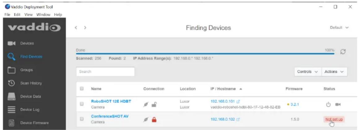
- For each device that you need to work with, select Not Set Up and set the admin password.
You can now access the administrative web interface for system administration and other configuration tasks.
Manual Access and Initial Device Set-Up
If you do not use a Vaddio Device Controller or the Vaddio Deployment Tool, you will need to complete the initial device set-up manually, by browsing to the device's web interface using its IP address. See Getting the Camera's IP Address.
Initial Access to the Web Interface
HTTP access is disabled initially. Enter the camera's IP address in your browser's address bar using https://as a prefix. (Example: https://10.30.200.125) When you access the web interface without using the https://prefix, the browser may treat it as a search query, or you may encounter this message:
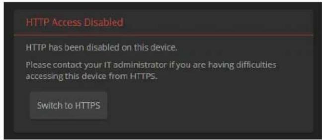
Switch to HTTPS if you see this message.
Expect a security warning from your browser the first time you access the device's web interface.
Different browsers will respond with different messages and options. Your browser will probably present a message indicating one of these things:
■ The connection is not private
■ The site is not secure
■ The site is not trusted
■ The site poses a security threat
This is because the certificate (the product's website security credential) is self-signed, not issued by an external certificate authority. Your HTTPS connection is secure and traffic is encrypted.
You will need to make the selections that your browser's security message discourages. Depending on the browser, the warning presents an option to learn more, view details, or go to the "Advanced" page. When you select this, your browser provides an explanation and a button or link to continue to the IP address you entered, with a reminder that it may be unsafe. Select the option to continue. Your HTTPS connection is safe.
After you have accessed the product's web interface once, your browser may remember its IP address and not present the security message again.
Completing the Initial Device Set-up
Set the admin password and complete any other required tasks, such as accepting agreements. The full administrative interface opens when you finish.
Note
This page includes a link to the company's standard privacy policy. This product does not record audio or video files, and it does not store any identifying information other than what you may enter on the Room Labels page of the web interface. However, the device's IP address is cons "personally identifiable information" for the purposes of the privacy policy.
System Administration
This chapter covers settings for managing the camera as an element of your network.
■ Security – Passwords, guest access, other IT security-related settings
■ Network configuration
■ Time settings
See Configuring Camera Behavior for information on image adjustments, streaming configuration, and other items related to camera behavior.
Note
Vaddio products are designed with very similar web interfaces. The screen shots in this manual is slightly different from your camera's web interface. Some may be from other cameras.
Configuring Access and Other Security Settings
SECURITY PAGE
The Account Passwords and Web Server areas of the Security page provide basic security for the web interface:
- Admin password – Required. The web interface is unavailable if no admin password is set.
- User password – Password-protected access to the operator's page of the web interface.
- Allow Guest Access – Allow access the operator's page without a password. Disabled by default.
■ Automatically Expire Idle Sessions – Automatically logs you out after 30 minutes of inactivity.

Other security settings include:
- Allow Telnet Access – disabled by default.
- Allow Zeroconf DNS-SD discovery – allowed by default.
■ Advanced Settings – Enable HTTP access (disabled by default) and Manage SSL Certificate.
Note
Consult your network security specialist before changing any of these settings. Seek explicit guidance concerning the SSL certificate.
Configuring the Camera for Your Network
By default, the camera is set to DHCP, and will receive an IP address automatically if your network assigns IP addresses. Work with your network specialist to ensure that the camera is configured to comply with the organization's network policies.
Caution
Consult your IT department before changing network settings. Errors in network configuration can m the camera inaccessible from the network.
Note
When you change the camera's hostname, IP address, or other network information, you will need in to the web interface again. This does not happen if the only change you make is from DH addressing or vice-versa.
Configuring the Device with a Static IP Address
NETWORKING PAGE
If no DHCP server is available to automatically assign an IP address, the camera uses its default IP address (169.254.1.1). If you install more than one camera or other device on this network, you must follow this procedure to prevent IP address conflicts.
If the camera is currently at 169.254.1.1:
- Work with your IT department's network specialist to determine the correct network settings.
- Connect your computer's network port to the camera's network port.
- Set IP Address to Static. Then enter the IP address, subnet mask, and gateway. DNS Server is optional; ask the network specialist.

If the camera is currently at an IP address other than 169.254.1.1:
Work with your IT department to determine whether the device's current IP address is suitable.
If it is, you only need to set the IP Address to Static.
If not, set IP Address to Static and enter the IP address, subnet mask, and gateway as directed. Again, DNS Server is optional; ask the network specialist.
Changing the Camera's Hostname
NETWORKING PAGE
If your network supports hostname resolution, you can browse to the camera using its hostname. Giving it a simple, easy-to-remember hostname means you don't need to know its IP address. Work with your IT department to ensure that the new hostname conforms to the organization's naming conventions.
Note
You may need to log in to the web interface again after changing the hostname.
Specifying Time Zone and NTP Server
NETWORKING PAGE
Using automatic NTP updating ensures that the timestamps in the camera's diagnostic log are accurate. Specifying your time zone may make it easier to match logged events with other actions and external events.
- To make the time zone and NTP server editable, enable Automatic NTP Updating.
- If you are not sure what to use for NTP Server, use the default.
- Select the desired time zone from the list.
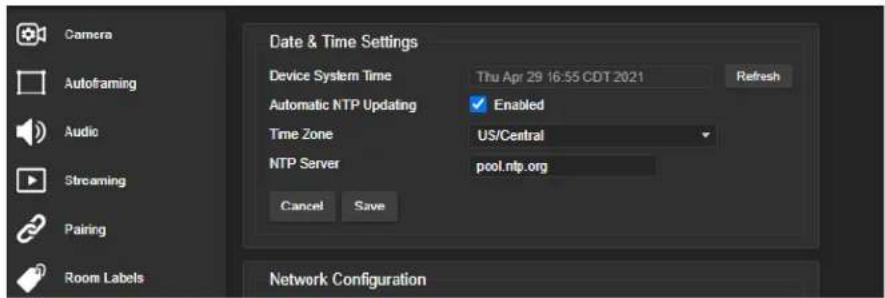
You may need to refresh the system time display.
Adding Room Information to the Camera's Web Interface
ROOM LABELS PAGE
The information you enter on this page is displayed on every page of the web interface. In a multi-camera environment, you may also wish to specify what appears on the browser tab.

Configuring Camera Behavior
This chapter covers settings for defining how the camera performs in your environment:
■ Autoframing adjustments
■ Streaming
■ Manual-mode settings and adjustments – presets, color and lighting, speed, focus
■ Audio adjustments
■ Other camera settings
Fine-Tuning Autoframing Behavior
The Autoframing feature can be tuned to your specific installation. This includes defining areas where the camera does not evaluate motion (masking), adjusting the tracking area, speed, sensitivity, and responsiveness.
How It Works: Digital Pan/Tilt/Zoom
Optical Zoom and Electronic Zoom are the names of two Autoframing adjustments, in addition to being simple terms for the two ways that a camera can zoom. This section talks about how zooming works.
The lenses in a camera control how much of the room can be in the shot – the image area. Zooming in optically makes the image area smaller by moving the lenses. Zooming in digitally makes the image area smaller by using the pixels from a smaller portion of the image sensor. Either way, the effect is the same: When the image area is smaller, everything in the shot looks bigger.
Digital pan and tilt work when the camera is zoomed in. If some image area is available outside the shot, the camera can pan and tilt by moving the image area to use pixels outside the current shot. As the camera zooms in, the image area is a smaller part of the total field, so more pan and tilt is available. But if the current shot uses all the pixels, there's no room to pan or tilt.
The unmasked portion in each frame of the diagram represents the zoomed image while the camera pans from the Mars globe to Dr. Sagan.

natural_image
Four-panel photo collage showing people in business attire posing with globe-like objects on a table, no visible text or symbols.How It Works: Autoframing
Autoframing is based on motion detection. It won't mistake pictures for people, it still works if you turn away from the camera, and you don't have to wear a special device. But with no special device to follow, Autoframing does not necessarily keep the shot on its original subject.
Autoframing pans and tilts to center the source of motion, so the image is almost always zoomed in at least slightly.
■ Autoframing is enabled by default.
■ The camera tries to keep the frame centered on the source of motion.
■ If the motion is small, the camera zooms in.
- When the camera does not detect any motion, by default it zooms out. This behavior is configurable.
■ If the motion is near the edge of the field of view, it can't be centered in the frame.
■ If the motion is mostly outside the field of view, the camera can only detect the small part of the motion within its field of view.
In this diagram, the unmasked area represents the tracking area. The area of motion is large (which limits the zoom) and the two people on the left are near the edge of the total field of view, so the camera cannot pan far enough to center the people in the frame.

natural_image
Group photo of four men in business attire gathered around a table with a globe and trophy, in an office setting (no visible text or symbols)Basic Autoframing Adjustments
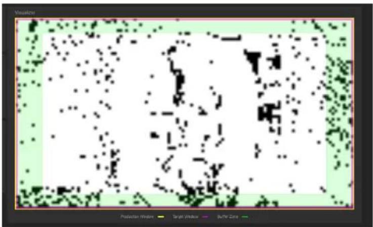
AUTOFRAMING PAGE
When making adjustments, compare the Visualizer's image to the video output.
Optical Zoom - Sets the area in which motion can be tracked. Adjust this first.
Autoframing Presets – Factory configurations. "Conservative" settings are less sensitive and track at lower speeds than "responsive" settings. Select the one closest to the room's requirements, then make other adjustments if needed.
Note
In many cases, the camera delivers good Autoframing performance with no adjustments beyond set the optical zoom and selecting the appropriate Autoframing preset.

Sensitivity – How quickly the camera responds to new motion. High sensitivity may respond to brief, unwanted motion, such as people walking past an open door. Typically 70% to 90% for conferencing, 95% or higher for lecture capture.
Noise Threshold – The minimum change recognized as motion. Default value is 20%. If Noise Threshold is high, the Visualizer shows less movement data (white dots). If Noise Threshold is too low, the Visualizer shows pixel changes that are not motion, such as camera noise and small changes in lighting.
Persistence – How long the camera remembers motion and stays on its source after other trackable motion starts. Typically 25% to 100% for conferencing, below 15% for lecture capture.
Shot Margin – Controls how tight or wide the shot will be around the people in the camera's field of view.
A high value will result in a wider shot and a low value results in a tighter shot around the person or group of people. Default value is 7% for conferencing and 13% for lecture capture.
Max ePTZ Speed – The maximum speed for pan, tilt, and zoom while tracking. Low speed may lose fast-moving motion sources. High speed may seem jumpy. Typically 5 to 6 for conferencing, 12 to 18 for lecture capture.
Masking Unwanted Motion
AUTOFRAMING PAGE, MASKING TAB
Masks are areas where the camera ignores motion. For example, if a door is within the camera's field of view, a mask can prevent the camera from responding to the movement of the door or people in the doorway. You can create multiple masks to fine-tune the camera's performance.
Things to know about masks:
- When you select the Masking tab, the Autoframing Visualizer mode automatically switches to a view of the room, so you can see what part of the room each mask affects.
■ After you select Add Mask, drag the new mask to the desired location. Adjust its dimensions by dragging its corners or edges.
■ Right-click the mask name to rename it. - Clear a mask's Enabled check box to disable the mask without deleting it.
■ Set the Visualizer mode to Motion to test the mask.

Advanced Autoframing Adjustments
AUTOFRAMING PAGE
Max Electronic Zoom – Sets the default size of the tracking frame relative to the area defined by Optical Zoom. Default value is 3x for all Autoframing presets.
Initial Persistence – How the camera remembers motion when it starts; similar to Persistence. Typically 25% to 100% for conferencing, 0 for lecture capture or presenter tracking.
Responsiveness – How quickly Autoframing reacts to new motion. Typically 70% to 90% for conferencing, 95% or higher for lecture capture.
Buffer Zone – The area around the edge of the frame where new motion causes the image to re-center.
Typically 3% for conferencing, 7% for lecture capture. Adjust this value higher to make the camera move less.
Tri-Sync Motion - Smooth pan/tilt/zoom. When Tri-Sync Motion is disabled, the camera snaps to position presets. Enabled by default.
Forced Wait Time - Minimum number of seconds between camera movements. Default is 0. Increasing Persistence often provides better performance than setting a Forced Wait Time.
History – History data is used for motion detection. High settings are best for conferencing and other low-motion situations, because they allow the camera to detect small motions such as changes in expression; but they increase latency. Low History settings provide more reactive tracking, with the possible drawback that the camera moves away from a motion source that pauses, and may not respond to small motions. Low History settings are best for lecture capture and other high-motion uses.
Default Wide - In Default Wide mode, the camera widens the shot (zooms out) when it detects no motion. This is best for conferencing or other situations with low motion. When Default Wide is not enabled, the camera remains where it last detected motion. We recommend disabling Default Wide mode for lecture capture.

Autoframing Adjustment Quick Reference
Set Optical Zoom and select the Autoframing preset that is most similar to the room's requirements. Then adjust Autoframing to meet the unique demands of your space. These tables may help.
Not Tracking Enough
| To correct this Do this For this effect | ||
| Autoframing isn't working Resume | Resume Autoframing; avoid using manual controls | Manual controls override Autoframing |
| Autoframing takes too long start | Increase Responsiveness and Sensitivity | "Notice" motion sooner |
| Decrease Initial Persistence Respond to motion sooner | ||
| The camera only frames participants who move frequently | Increase Sensitivity Recognize smaller movements, such as participants who don't gesture or fidget | |
| Decrease Noise Threshold Recognize brief motion | ||
| The presenter moves faster than the camera | Increase Max ePTZ Speed and SRRat, tilt, and zoom faster Margin | |
| The presenter keeps moving out of the frame | Increase Responsiveness "Notice" | motion sooner |
| Decrease Initial Persistence Respond to motion sooner | ||
| Decrease Optical Zoom Enlarge the tracking area | ||
Tracking Too Much
| To correct this Do this effect | ||
| The camera keeps moving away from the person who speaking | Increase Persistence Stay on the is | last source of motion longer |
| Increase Noise Threshold Require | movements to be bigger before they are evaluated | |
| Movement seems jumpy Dec | crease Max ePTZ Speed | Slower camera movements |
| Increase Buffer Zone | Fewer camera movements | |
| The camera keeps zooming too far | Reduce Max Electronic Zoom | Limits how far the camera can zoom in while tracking |
| The camera recenters even when the presenter is still within the frame | Increase the Buffer Zone Enlarges | the area where new movement does not cause the camera to recenter |
Managing Audio
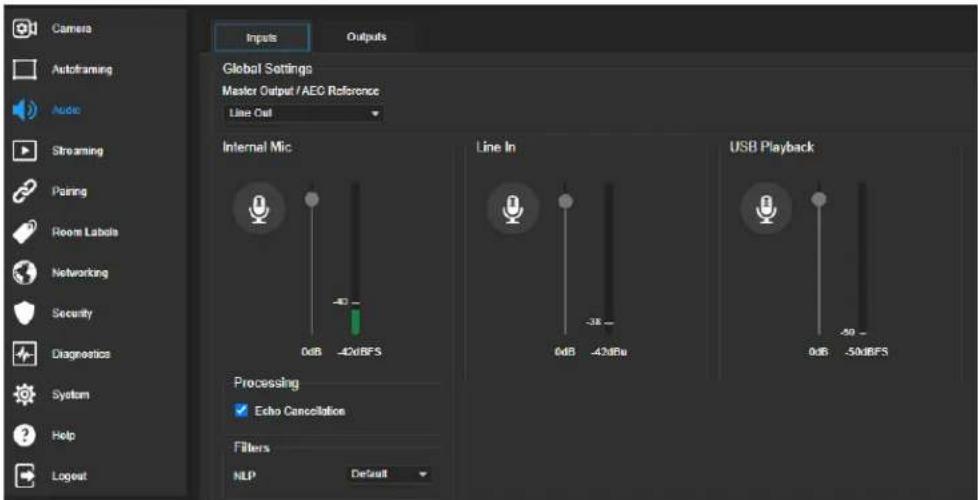
AUDIO PAGE
Controls for individual inputs (audio from your site) and outputs (audio from the far end of the conference) are on separate tabs.
To mute all audio inputs together:
To stop sending audio, use the audio mute button at the top of any page of the web interface.

To mute or control volume for individual audio inputs or outputs:
Use the button to mute the desired audio input or output. Use the slider for the appropriate audio input or output to set the volume.
Note
For best performance with most computers, we recommend setting the USB Record volume high. allows people at the far end of the call to adjust the audio to their environment.
Other Audio Settings and Adjustments
To adjust microphones for best far-end audio performance:
Select the desired adjustments:
- Echo Cancellation – Keeps microphones from feeding the speaker output back into the system. Under most circumstances, echo cancellation is desirable. Echo cancellation is on by default.
■ Master Output/AEC Reference – The source for the far-end audio to be canceled from the signal that the built-in microphone picks up. Select Line Out to use the connected speaker as the reference, or HDMI Out to use the built-in speakers of the connected HDMI display. - NLP (non-linear processing) filter – Select Reverberant to correct for poor acoustical treatment in the room.
To sync the sound with the video in the IP stream:
On the Outputs tab, check the Delay box and enter a delay value in milliseconds.

About Echo Cancellation
When a microphone picks up the audio from a speaker (far-end audio) during a conference, it sends the far-end audio back to the participants at the far end, creating an echo. Acoustic echo cancellation prevents this.
Here's how it works:
- The speaker feeds the far-end audio into the room. This signal also goes to the audio processor as the reference that needs to be canceled.
- The audio processor inverts the signal and sends it to the microphone.
- The sum of the audio that the microphone picks up from the speaker and the inverted signal is 0: The echo is canceled.

— Far-end audio signal
— Inverted audio signal
With the audio from the speaker canceled out, the audio from the microphone includes only the sounds originating at your end of the conference.
Configuring Streaming Behavior
Conferencing applications use USB streaming. After initial device set-up is complete, the camera's USB stream is always enabled.
IP streaming is disabled by default.
Notes
The screen shots in this section are representative, and may differ from what you see. Some m other Vaddio products.
You may be prompted to reboot the camera when you save changes to the streaming settings.
Viewing the USB Stream
Do one of these things:
■ Start or join a conference.
- Open a stream viewer and select the camera as the video capture device.
The image below shows how to view a camera's USB stream using VLC Media Player. The media player will correctly identify your camera by model.


Configuring USB Streaming
STREAMING PAGE
These settings affect how the camera works with soft conferencing applications.
USB Device Name – Specify how the camera shows up in your soft client's camera selection list.
HID Audio Controls – Enable to allow conferencing applications to control the audio.
Enable UVC Extensions – Allow conferencing applications to control the camera.
Depending on the conferencing application that you use, you may also need to change the USB stream format setting. See Additional Camera Settings.
Enabling or Disabling IP Streaming
STREAMING PAGE
IP streaming is disabled by default.
Two IP streaming protocols are available:
- RTSP streaming delivers an IP stream that people can access from your network using a media player.
- RTMP streaming sends a stream to a content service provider such as YouTube. To use RTMP streaming, you must have an account with a streaming service.
Viewing the IP Stream (RTSP)
- Open a stream viewer such as VLC Media Player.
- Select "Network stream" or your viewer's equivalent option.
- Copy the streaming URL from the camera's Streaming page and paste it into the viewer as the URL for the network stream.
The image below shows how you would view a camera's IP stream using VLC Media Player. The media player will correctly identify your camera by model.


RTSP Streaming Protocol and URL
STREAMING PAGE
When IP streaming is enabled and RTSP is selected, the RTSP stream is automatically available. Consult your IT department before changing these settings.
RTSP port: Vaddio strongly recommends using the default RTSP port number.
Path: The portion of the streaming URL that appears after the IP address. You may wish to change this to help identify the stream source – for example, demo-studio-3.
URL: The location where the stream can be viewed. This will change if you edit the path.

Setting up IP Streaming in Easy Mode
STREAMING PAGE
Note
Consult your network specialist when setting up IP streaming, to be sure that you select settings appropriate for the network.
If you are not sure about these settings, start with the defaults.
- Select Video Quality – High Quality, Standard, or Low Bandwidth.
- Select the desired IP streaming resolution. This determines the size of the stream viewer window.

Note
The IP streaming resolution and frame rate cannot be higher than the local video rate (see Additional Camera Settings).
Customizing IP Streaming Settings
STREAMING PAGE
Note
Consult your network specialist when setting up IP streaming, to be sure that you select settings appropriate for the network.
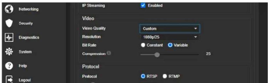
- Select Custom quality mode.
- Select the desired resolution and frame rate.
- Select Constant or Variable Bit Rate.
- Constant Bit Rate only: Set Max Bandwidth.
- Variable bit rate only: Set the Compression slider. Then save your changes.
Configuring RTMP Streaming
STREAMING PAGE
To use RTMP streaming, you must have an account with a streaming service.
To configure an RTMP streaming service:
- Select RTMP streaming, then select Settings.
- Expand the information box for the service.
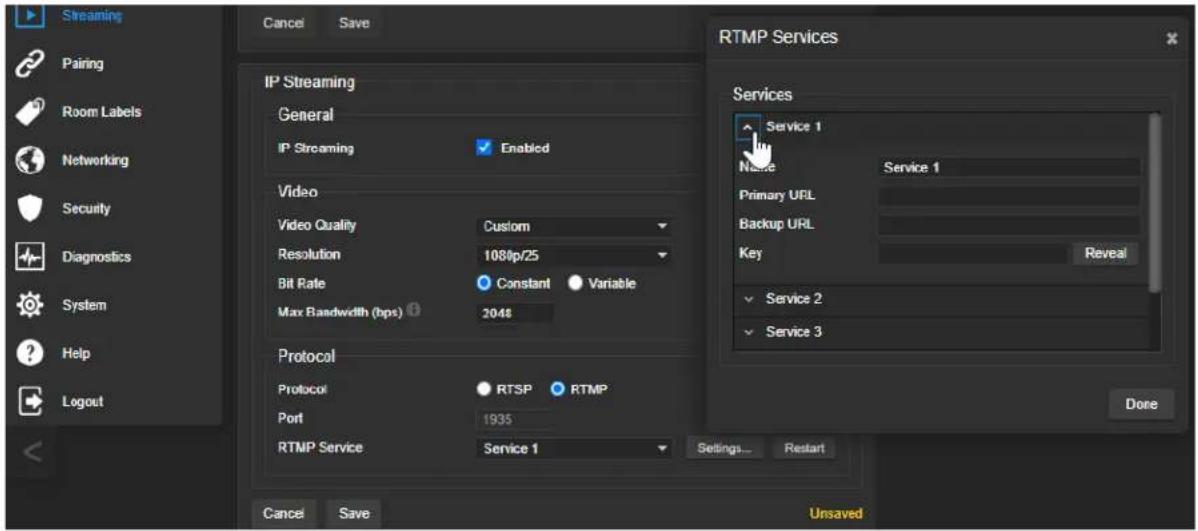
- Enter the name of the service.
- Paste in the key and URL(s) provided by the service.
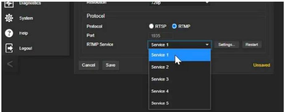
To select the enabled RTMP streaming service:
Expand the list of available streaming services, and select the one to use.
Note
When RTMP streaming is selected and a service is configured, the camera streams to that service you stop the stream.
Changing MTU
STREAMING PAGE, ADVANCED SETTINGS
The default packet size for streaming is 1400. Do not change this except in consultation with your network administrator.
Configuring Manual Mode Behaviors
Although Autoframing mode is normally used with this camera, there are times when you need conventional PTZ behaviors. This section covers:
■ Preset shots
■ Speed controls
■ Direction controls
These settings are on the Camera page of the web interface.
Setting the Home Position and Other Preset Shots
CAMERA PAGE
Although the camera's Autoframing feature is the simplest way to keep the focus on the presenter, there are times when you need a static shot – such as a zoomed-in shot of the room's dry-erase board.
Presets are saved shots. Each preset includes pan, tilt, zoom, and (optionally) color settings.
When Autoframing is not enabled, the camera returns to the Home preset when it comes out of Standby or reboots.
To store a preset:
- Set up the shot.
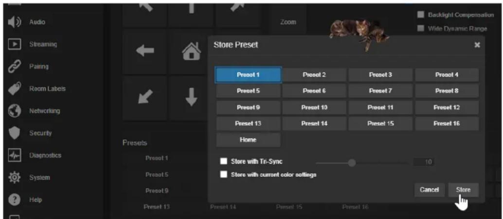
- In the Presets area, select Store to open the Store Preset dialog.
- Select the preset to store. The preset button changes color.
Note
The Store Preset dialog box does not indicate whether presets have already been defined, but main display dims the preset buttons if they have no preset information stored.
4. Select the behavior for the preset:
■ To save the preset with specific color settings, select Store with Current Color Settings.
■ To pan/tilt smoothly to the preset, select Save with Tri-Sync. Use the slider to control the speed.
■ The camera will cut to the preset if you leave the Save with Tri-Sync checkbox clear.
5. Store the preset.
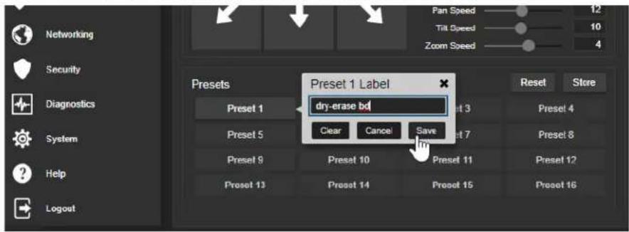
Renaming Presets and Custom CCU Scenes
CAMERA PAGE
You can rename presets and custom scenes to identify them. This also helps you identify and avoid overwriting them when you store new ones. The process is the same for both.
Right-click the button for the preset or custom scene, and edit the label.
Speed Adjustments
CAMERA PAGE
The following speed adjustments are available:
■ Manual pan, tilt, and zoom speeds – Used when you control camera movements with the RF remote or the arrow buttons in the web interface
- Tri-Sync – Only available when storing a preset. Specifies a speed for the camera to pan, tilt, and zoom to the shot, as a motorized PTZ camera would do. If you save the preset without Tri-Sync, the camera cuts to the shot instead.
Use the Pan Speed, Tilt Speed, and Zoom Speed sliders to adjust how fast the camera moves in response to the direction and zoom controls on the remote and in the web interface.

Setting the Direction for Camera Movements
CAMERA PAGE
By default, the arrow buttons on the remote and in the web interface show the direction the image frame moves from the camera's point of view. This may not suit your situation.
If the presenter will control the camera with the remote:
- Select Settings to open the direction control box.
- Set Pan Direction to Inverted to make the camera move to the presenter's left when they press the left arrow button.
Adjusting Color, Lighting, and Image Quality Settings
CAMERA PAGE
No two rooms are exactly alike – but a lot of rooms are a lot alike. The technical folks at Vaddio (Scott, to be specific) have already set up adjustments for common lighting scenarios (CCU scenes) – Incandescent Hi, Incandescent Lo, Fluorescent Hi, Fluorescent Lo, and Outdoor. The Auto setting allows the camera to determine the appropriate adjustments.
When adjusting for the room lighting, start with a factory-defined CCU scene and fine-tune the color and lighting as needed using the Color Settings controls. After you customize the camera's color and lighting settings, you can save the adjustments as a custom CCU scene.
■ Auto Iris allows the camera to compensate automatically for the light level. Clear this box to adjust iris and gain manually.
■ Backlight Compensation (available when Auto Iris is selected) reduces contrast to adjust for bright light behind the main subject of the shot. This setting can't be used with Wide Dynamic Range.
- Wide Dynamic Range (available when Auto Iris is selected) increases the contrast between the brightest and darkest areas. This setting can't be used with Backlight Compensation.
■ Auto White Balance adjusts color automatically. Clear this box to adjust red gain and blue gain manually.
- Red Gain and Blue Gain (available when Auto White Balance is not selected) provide manual color adjustment.
■ Detail adjusts the image sharpness. If the video looks grainy or “noisy,” try a lower Detail setting.
■ Chroma adjusts the color intensity.
■ Gamma adjusts the range (grey density) between bright areas and shadows.
The Lighting and Image Quality Quick Reference and Color Adjustment Quick Reference may be helpful.
If you make a change that you don't like, start over by selecting and then deselecting Auto White Balance.

Lighting and Image Quality Quick Reference
Here are some tips for using the CCU settings for lighting and image quality.
| What do you need to correct? Make this adjustment: | |
| The image is too dark Increase Iris (lower F-stop value) | value) |
| Increase Iris Gain | |
| The image looks washed out or faded Decrease Iris (higher F-stop value) | |
| The subject is silhouetted against a bright background Enable Backlight Compensation | |
| Highlights and shadows look right, but mid-tones are an increase Gamma too dark. | |
| Shadows are too dark Enable Wide Dynamic Range (WDR) | |
| The image looks grainy Decrease Detail | |
| Decrease Iris Gain | |
| "Soft focus" effect; the image looks unrealistically smooth | Increase Detail |
Color Adjustment Quick Reference
Here are some tips for using the color-related CCU settings.
| What do you need to correct? Make this adjustment: | ||||
| Colors look less vivid than they should Increase Chroma | ||||
| Colors look too vivid Decrease Chroma | ||||
| Colors look wrong; white objects do not appear white Enable Auto White Balance | ||||
| Disable Auto White Balance and...■ adjust Red Gain (decrease for less red, increase for less green)■ adjust Blue Gain (decrease for less blue, increase for less yellow) | ||||
| Too much red Not enough red Too much blue Not enough blue Balanced | ||||
 |  |  |  |  |
If you are adjusting for lighting conditions that are likely to recur, you can.
Saving Color and Lighting Settings
CAMERA PAGE
If you are adjusting for lighting conditions that are likely to recur, you can save your adjustments as a custom scene or store them as an element of the presets you set up.
-
Select Store CCU Scene.
-
In the Store CCU Scene dialog box, select the custom scene to store (Custom A, B, or C) and select Store. The button for this scene becomes available in the web interface.
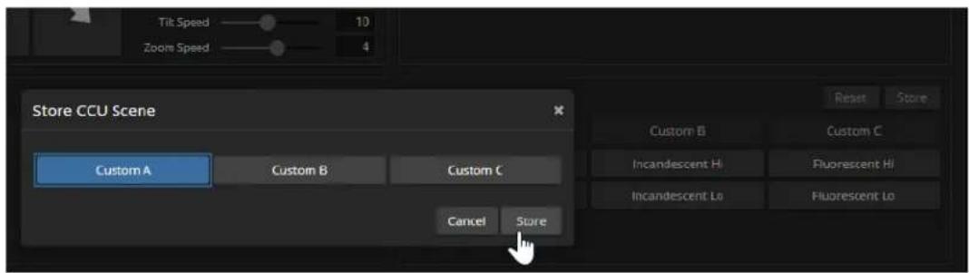
- Optional: Right-click the button for your custom CCU scene, and enter a short name for it in the text box that opens. Save the name.
Adjusting the Focus
CAMERA PAGE
Open the Focus control to select Auto-focus, or set manual focus with the + (near) and - (far) buttons. The + and - buttons only work when Auto Focus is not selected.
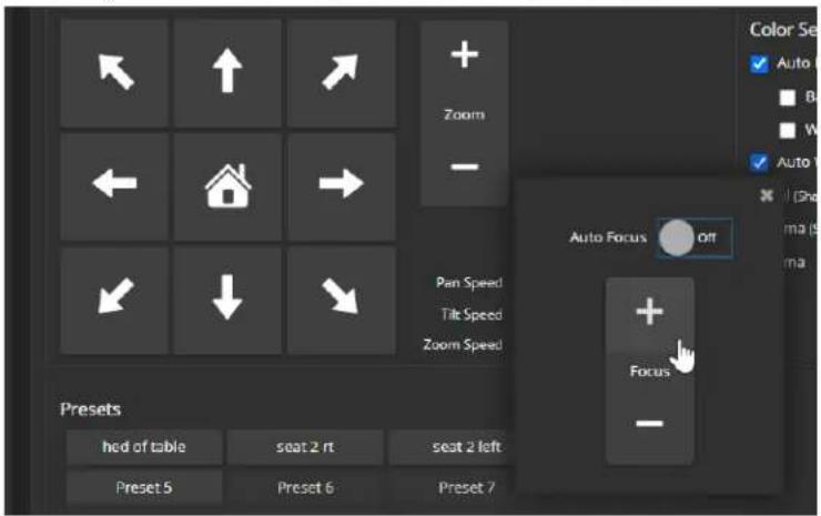
Focus control is available to non-administrative users via the RF remote.
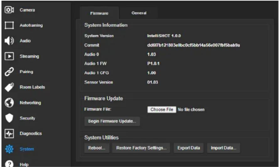
Additional Camera Settings
SYSTEM PAGE, GENERAL TAB
Additional settings are available on the General tab on the System page.
LED On – In most cases, Vaddio recommends leaving the status lights on, to let people in the room know whether the camera is currently sending video.
LED On in Standby - Select Disabled to turn off the LED when the camera is in standby mode.
LED Color Scheme – Status light color codes for Unified Communications (conferencing) or Pro AV (broadcast). Default is UC.
Point Light Compensation – Reduces the intensity of small, extremely bright areas (point light sources) that would otherwise swamp the camera with light and make it difficult to see details in areas with less intense lighting.
HDMI Color Space - Set the color space for the HDMI output to YCbCr (default) or sRGB.
Image Flip – If mounting the camera upside-down, set Image Flip ON. This orients the video image correctly and sets the camera to respond appropriately to tilt commands from the remote, web interface, and connected control devices.
Video Output Resolution – Select the desired resolution for the HDMI output. IP streaming is set separately. See Setting up IP Streaming in Easy Mode.
UVC Mode - USB stream format. Client Custom enables far-end camera control when used with the Zoom soft client. Use the default UVC Compliant setting with most other conferencing applications.

Operating the Camera
When you need to control the camera in manual mode rather than using Autoframing, you can use
■ The RF remote
■ The web interface (accessible from your computer's browser or using a Vaddio Device Controller)
■ A third-party control device
When you use the manual controls, Autoframing pauses. It's similar to cruise control in a car: Using a preset or directional control is like tapping the brake pedal. The camera remains under manual control until you resume Autoframing.
Operating the Camera from the Web Interface
CAMERA PAGE (USER OR GUEST ACCESS)
By default, the operator's page of the web interface is not available. The administrator must set a password for the user account or enable guest access.
Only the operator's page is available with user or guest access.
The operator's Camera page provides most of the same controls as the remote:
■ Audio and video mute
■ Camera standby
■ Pan, tilt, and zoom
■ Camera presets, if any have been stored
■ Custom color/lighting settings, if any have been stored

Muting Audio and Video
Use the audio mute button to stop sending audio. Use the video mute button to temporarily stop sending video from the camera without placing it in standby.
Use the RF remote to control volume.
Managing the Camera Ready State
Use the Standby button to switch between low-power (standby) and ready states.

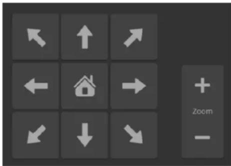
Moving the Camera
Use the arrow buttons for camera pan and tilt. The center button moves the camera to the home position.
Zooming In or Out
Use the Zoom + button to zoom in and the Zoom - button to zoom out.
Moving the Camera to a Preset Position
Use the Preset buttons (if available) to move the camera to any of its programmed positions. Presets are only available if they have been set in the administrative interface or with the RF remote.
Operating the Camera with the RF Remote
The RF remote provides basic in-conference functionality – pan, tilt, zoom, presets, volume control, and muting. You can also use it to get the camera's IP address. When you have the IP address, you can open the camera's web interface.
Before you can use the remote, you will need to:
■ Install the batteries
■ Pair the remote with the camera
IntelliSHOT cameras are not compatible with IR remotes.
Installing the Batteries
The remote uses two AAA batteries.
- Remove the cover from the back of the remote. You may need to press down on the inner edge while sliding it off.
- Install the batteries as shown in the diagram in the battery opening.
- Slide and snap the cover back into place.
Pairing the Remote to the Camera
The camera does not recognize or respond to the remote until they are paired. Do this after the camera is turned on and its status light is white.
If you do not have access to the administrative web interface:
- Press and hold the IP button on the connector panel until the status light blinks cyan.
- While the status light blinks cyan, press the pairing button on the remote. The camera's status light changes to steady white when the pairing is complete. You may need to press the remote's pairing button more than once.
- If the status light changes from blinking cyan to blinking blue, this indicates a pairing error: The pairing was not successful and pairing mode has timed out. Go back to step 1. If the problem persists, contact Vaddio Technical Support.
Note
Any time a pairing error occurs (status light blinking blue), Vaddio recommends rebooting the cam soon as feasible. If pairing was successful, the remote remains paired through the reboot process.
If you have access to the administrative web interface:
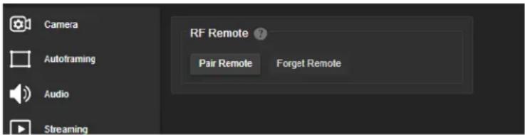
- On the Pairing page of the web interface, select Pair Remote.
- When the camera's status light blinks cyan, press and hold the pairing button on the remote until the status light changes to steady white.
RF Remote Quick Reference
 | Indicator and Power button - Set the camera to mode, or return to full-power mode. | standby |
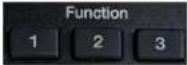 | Function buttons - Reserved for future use. | |
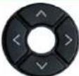 | Arrow buttons - Pan and tilt. Autoframing pauses if these buttons. | |
 | Home button - Resumes Autoframing if it is paused | |
 | Network button - Display the camera's IP address on the video output. | |
 | Pairing button - Use when pairing the remote with the camera. | |
 | Mute button - Mute the microphone(s). | |
 | Reserved for future use. | |
 | Volume +/- button - Increase or decrease the volume of the connected speaker. | |
 | Focus +/- buttons - Adjust the focal distance in or when Manual focus mode is selected. | |
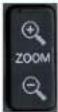 | Zoom +/- button- Increase or decrease the zoom. | |
| Auto Man | Auto and Man buttons - Select automatic or manual focus. | |
 | Preset buttons - Set, clear, or select preset shots. Autoframing pauses if you use these buttons. |
Other Things to Know About the Remote
Here are some common situations in which the remote can behave in ways you don't expect.
- Environments with cameras in adjacent rooms – If the remote is currently paired to a camera and within range of that camera, it will not pair with another camera.
■ The remote goes to standby mode after a brief period of inactivity. Press a button to wake it up. - The remote is no longer paired after restoring the camera's factory defaults. If you restore factory defaults on the camera, pair it with the remote again.
Unpairing the Remote
PAIRING PAGE
If you need to unpair the remote from the camera that currently recognizes it, you will need admin access to the camera's web interface. On the Pairing page, select Forget Remote.
System Maintenance
This chapter covers tasks for keeping your system up-to-date and operating properly:
■ Rebooting
■ Backing up and restoring the camera configuration
■ Installing firmware updates
- Getting help
Saving (Exporting) or Restoring (Importing) a Configuration
SYSTEM PAGE, FIRMWARE TAB
If you need to restore a camera's factory default settings, you can export the configuration beforehand to restore customized information instead of re-entering it manually.
The data export includes home and other presets, NTP and time zone information, and room labels.
It does not include any information that is unique to the device, such as passwords, hostname, camera settings, or remote pairing.
To export a configuration:
Select Export Data. The export downloads to your computer as a .dat file. The filename is the camera's hostname.
To import a configuration file:
Select Import Data. The web interface prompts you to select the file to import.
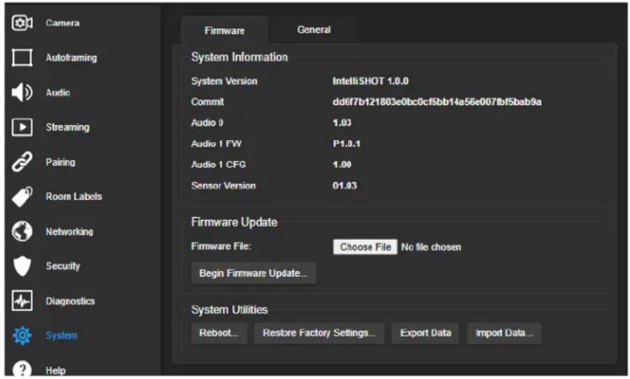
Installing a Firmware Update
SYSTEM PAGE, FIRMWARE TAB
Caution
Be sure the camera stays connected to power and to the network during the update. Interrupting update could make it unusable.
- Read the release notes and download the firmware update file from the product's web page at www.legrandav.com. The release notes can help you to decide whether to install the update.
- On the camera's System page, select Choose File. Then select the firmware update file that you downloaded. The filename ends with .p7m.
- Select Begin Firmware Update.
- Read and understand the information in the Confirm dialog box, then select Continue. A progress message box opens and the camera's status lights turn yellow. If the update process presents warnings or error messages, read them carefully.
The camera reboots to complete the update, and the web interface prompts you to log in again.
Rebooting the Camera
SYSTEM PAGE, FIRMWARE TAB
This can help if the camera stops responding as you expect.
In the System Utilities section, select Reboot.
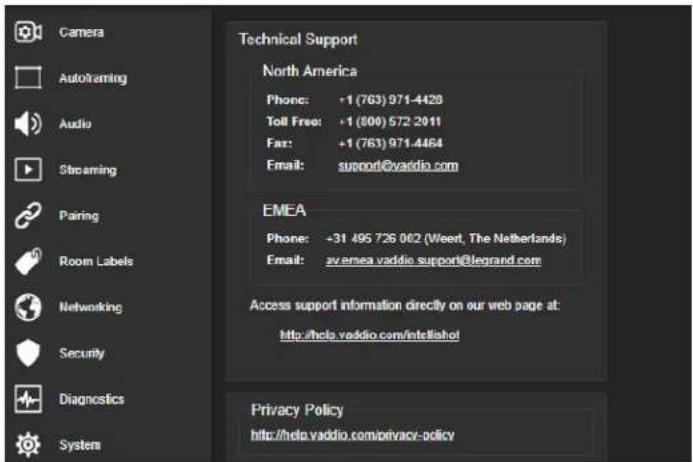
Contacting Vaddio Technical Support and Viewing Diagnostic Logs
HELP PAGE, DIAGNOSTICS PAGE
If you can't resolve an issue using your troubleshooting skills (or the Troubleshooting tables in this manual), we are here to help.
You'll find information for contacting Vaddio Technical Support on the Help screen.
Note
The Help page links to our standard privacy notice. This product does not record or save video store any identifying information except what you enter on the Room Labels page. However, the camera's IP address is considered "personally identifiable information" for the purposes of the private notice. This information is stored for display to the user, but not otherwise shared or transmitted.
Your technical support representative may ask you to download the event log file from the Diagnostics page. The log may include large numbers of internal events even when no errors have occurred. Rebooting generates over 100 log entries.
![Camera Autoframing Audio Steaming Pairing Room Labels Networking Security Diagnostics System Help Logout Diagnostics Apr 21 22:24:37 vaddio-intellishot-68-27-19-07-FA-56 kernel: [ 1.421612] xinx-drm xinx orm.vt bound amca_pigw-drm_pl_enc_noml (cps &nd) Apr 21 22:24:37 vaddio-intellishot-68-27-19-07-FA-56 kernel: [ 1.420426] [dmj] initialized xinx i.o.0 20138509 for amca_pigw/drm_pl_c0 Apr 21 22:24:37 vaddio-intellishot-68-27-19-07-FA-56 kernel: [ 1.428984] xinx-encoder amca_pigw-drm_pl_enc_noml (ummy xilinx PL disp) Apr 21 22:24:37 vaddio-intellishot-68-27-19-07-FA-56 kernel: [ 1.451736] input: goto@i1 as /devices/platform/gpiq@31/input/inputu Apr 21 22:24:37 vaddio-intellishot-68-27-19-07-FA-56 kernel: [ 1.458745] file: not disabling unused clocks Apr 21 22:24:37 vaddio-intellishot-68-27-19-07-FA-56 kernel: [ 1.469878] also device list: Apr 21 22:24:37 vaddio-intellishot-68-27-19-07-FA-56 kernel: [ 1.469880] net: sylon.loglizs u Apr 21 22:24:37 vaddio-intellishot-68-27-19-07-FA-56 kernel: [ 1.499990] waiting for root device /dev/mmcbliepa... Apr 21 22:24:37 vaddio-intellishot-68-27-19-07-FA-56 kernel: [ 1.504085] mcbki: new HSSM RPC card at address ones Apr 21 22:24:37 vaddio-intellishot-68-27-19-07-FA-56 kernel: [ 1.508333] mcbikkeboota: mccr:0001 QZ34A partition 1 2.00 kib Apr 21 22:24:37 vaddio-intellishot-68-27-19-07-FA-56 kernel: [ 1.516735] mcbikkebootb: mccr:0001 QZ34A partition 2 2.00 kib Apr 21 22:24:37 vaddio-intellishot-68-27-19-07-FA-56 kernel: [ 1.523304] mcbikkerpub: mccr:0001 QZ34A partition 3 S12 kib, chardev (z Apr 21 22:24:37 vaddio-intellishot-68-27-19-07-FA-56 kernel: [ 1.536818] mcbikan: pt p2 ps p4 < ps p6 p7 p8 > Apr 21 22:24:37 vaddio-intellishot-68-27-19-07-FA-56 kernel: [ 1.557654] VFS: Mounted root (ext4 filesystem) readonly on device i79;3. Apr 21 22:24:37 vaddio-intellishot-68-27-19-07-FA-56 kernel: [ 1.566980] devtmpfs: mounted Apr 21 22:24:37 vaddio-intellishot-68-27-19-07-FA-56 kernel: [ 1.589783] Frezing unused kernel memory: 444C Apr 21 22:24:37 vaddio-intellishot-68-27-19-07-FA-56 kernel: [ 1.574312] run /sbin/init as init process Apr 21 22:24:37 vaddio-intellishot-68-27-19-07-FA-56 kernel: [ 1.743445] hbl: loading out-of-tree module taints kernel. Apr 21 22:24:37 vaddio-intellishot-68-27-19-07-FA-56 kernel: [ 3.838147] random: dd: uninitialized orandon read (S12 bytes read) Apr 21 22:24:37 vaddio-intellishot-68-27-19-07-FA-56 kernel: [ 4.017718] random: crng init done Apr 21 22:24:41 vaddio-intellishot-68-27-19-07-FA-56 watchdog[1219]: starting daemon (5.15): Apr 21 22:24:41 vaddio-intellishot-68-27-19-07-FA-56 kernel: [ 5.036447] configfs-gadget gadget: uwc_function_bind Apr 21 22:24:42 vaddio-intellishot-68-27-19-07-FA-56 kernel: [ 10.310970] pps ppsb: new PPS source ptp0 Apr 21 22:24:42 vaddio-intellishot-68-27-19-07-FA-56 kernel: [ 10.323807] mcb fffc000a.ethernet gcn-ptp-timer stp clock registered. Apr 21 22:24:46 vaddio-intellishot-68-27-19-07-FA-56 kernel: [ 14.415664] mcb fffc000a.ethernet ether link up (1000/full) Apr 21 22:24:50 vaddio-intellishot-68-27-19-07-FA-56 watchdog[1219]: retry timed-out at 5 seconds for /etc/watchdog.d/vaddio-framing Apr 21 22:25:01 vaddio-intellishot -G8 -C7 -E9 -O7 -F A -S G roct : rotating /var/log/boot to /media/vng-logs/ Download Refresh Clear Restore Auto-Resh](/content/2026/05/1041143/images/3030944f8613c13763c883a9cf368cc509b7e33ca9bae6c7f6df4f7bb0ba531b.jpg)
Telnet Serial Command API
The Vaddio Telnet command API allows an external device such as an AMX or Crestron presentation system to control the camera. It is also used for writing macros.
Requirements
- Telnet must be enabled on the Security page of the device's web interface.
- Your computer must have a Telnet client. Telnet port 23 is used.
- Your computer must be able to connect to the device over the network.
■ When you connect via Telnet, you must log in using the admin account.
Usage Notes
■ The > character is the command prompt.
- In addition to the camera control commands, Telnet session management commands are available – help, history, and exit.
■ CTRL-5 clears the current serial buffer on the device.
Getting More Information
Use a question mark as a command or command parameter to display a list of available commands, subcommands, or command parameters. For example, ? returns all top-level commands; network ? returns the valid subcommands for the network command; and network ping ? returns the parameters available for the network ping command.
To discover the valid range of values for a command, use a value that you expect to be out of range. For example, camera zoom set 64 returns an error message stating the valid range of zoom values. Firmware updates sometimes implement new commands or command parameters. We do not update the manuals for every firmware update, and occasionally the author makes a mistake. Querying returns the command parameters that are currently available, along with guidance on command syntax.
Typographical Conventions
■ {x | y | z} - Choose x, y, or z.
-
- < x - y > - Valid range of values is x through y.
■ [parameter] – Parameter is optional.
Autoframer Commands
Commands to manage and adjust Autoframing fall roughly into three categories.
Status commands:
■ autoframer enabled
■ autoframer paused
Shot definition commands:
■ camera optical-zoom
■ autoframer shot-margin
■ autoframer max-electronic-zoom
■ autoframer buffer-zone
Autoframing behavior adjustment commands:
■ autoframer sensitivity
■ autoframer responsiveness
■ autoframer initial-persistence
■ autoframer persistence
■ autoframer max-speed
■ autoframer noise-threshold
■ autoframer tri-sync-motion
■ autoframer forced-wait-time
autoframer enabled
Enable or disable Autoframing. This is normally on. Use the autoframer paused command to switch to manual mode with the intent of resuming Autoframing.
| Synopsis autoframer enabled {get | off | on | toggle} | ||
| Options | get | Returns the current enable state for Autoframing |
| off | Turns off Autoframing | |
| on | Turns on Autoframing | |
| toggle | Changes the Autoframing state | |
| Examples | >autoframer enabled offOK>Stops Autoframing, placing the camera in manual mode.>autoframer enabled getautoframer enabled: falseOK>Returns the current state of Autoframing. | |
autoframer paused
Pause or resume Autoframing. Autoframing pauses automatically when the camera receives a pan, tilt, zoom, or preset recall command from any source.
| Synopsis autoframer paused { get | off | on | toggle } | ||
| Options | get | Returns the pause state for Autoframing |
| off | Turns off the pause state (restarts Autoframing) | |
| on | PausesAutoframing | |
| toggle | Changes the Autoframing pause state | |
| Examples | >autoframer paused onOK>Pauses Autoframing, placing the camera in manual mode.>autoframer paused getautoframer paused: trueOK>Returns the current pause state of Autoframing. | |
autoframer default-wide
Specify how the camera behaves when it detects no motion. This setting is on by default.
| Synopsis autoframer default-wide {get | off | on} | ||
| Options | get | Returns the state of the Default Wide setting (on or off) |
| off | Turns off Default Wide mode. The camera remains on the shot where it last detected motion. | |
| on | Turns on Default Wide mode. The camera zooms all the way out when it detects no motion. | |
| Examples | >autoframer default-wide offOK>Turns off Default Wide mode. The camera does not zoom out to "search" for motion.>autoframer default-wide getdefault wide: falseOK>Returns the current state of the Default Wide setting. | |
camera optical-zoom
Adjusts the area in which Autoframing can occur.
| Synopsis camera | optical-zoom { in [] | out [] | stop | get ] } | |
| Options | in | Zooms the camera in. |
| out | Zooms the camera out. | |
| speed [1 - 7] | Optional: Zoom speed (integer). | |
| stop | Stops the camera's zoom movement. | |
| get Returns the camera's zoom | setting. | |
| Examples | >camera zoom inOK>Zooms the camera in at the default speed.>camera zoom out 7OK>Zooms the camera out at its highest speed.>camera zoom stopOK>Stops the camera's zoom motion. | |
autoframer buffer-zone
Get or set the size of the Autoframing buffer zone.
| Synopsis autoframer buffer-zone { get | set} | ||
| Options | get | Returns the current value for the Autoframing buffer zone |
| setSets the Autoframing buffer zone | ||
| Examples | >autoframer buffer-zone set 10OK>Sets the buffer zone to 10.>autoframer buffer-zone getautoframer buffer-zone: 10OK>Returns the current size of the buffer zone. | |
autoframer shot-margin
Get or set the size of the Autoframing shot margin.
| Synopsis autoframer shot-margin { get | set} | ||
| Options | get | Returns the current value for the Autoframing shot margin |
| setSets the Autoframing shot margin | ||
| Examples | >autoframer shot-margin set 15OK>Sets the shot margin to 15.>autoframer shot-margin getautoframer shot-margin: 15OK>Returns the current size of the shot margin. | |
autoframer sensitivity
Get or set Autoframing sensitivity.
| Synopsis autoframer sensitivity { get | set} | ||
| Options | get | Returns the current value for sensitivity |
| setSets Autoframing sensitivity | ||
| Examples | >autoframer sensitivity set 95OK>Sets the sensitivity to 95.>autoframer sensitivity getautoframer sensitivity: 95OK>Returns the current sensitivity value. | |
autoframer responsiveness
Get or set Autoframing responsiveness.
| Synopsis autoframer responsiveness { get | set} | ||
| Options | get | Returns the current value for responsiveness |
| sets Autoframing responsiveness | ||
| Examples | >autoframer responsiveness set 95OK>Sets responsiveness to 95.>autoframer responsiveness getautoframer responsiveness: 95OK>Returns the current responsiveness value. | |
autoframer initial-persistence
Get or set the initial persistence value.
| Synopsis autoframer initial-persistence { get | set} | ||
| Options | get | Returns the current value for initial persistence |
| setSets initial persistence | ||
| Examples | >autoframer initial-persistence set 15OK>Sets the initial persistence to 15.>autoframer initial-persistence getautoframer initial-persistence: 15OK>Returns the current initial persistence value. | |
autoframer persistence
Get or set Autoframing persistence.
| Synopsis autoframer persistence { get | set} | ||
| Options | get | Returns the current value for persistence |
| setSets persistence | ||
| Examples | >autoframer persistence set 15OK>Sets persistence to 15.>autoframer persistence getautoframer persistence: 15OK>Returns the current persistence value. | |
autoframer max-electronic-zoom
Get or set the value for the Autoframing maximum electronic zoom. This limits how far the camera zooms in for Autoframing.
| Synopsis autoframer max-electronic-zoom {get | set} | ||
| Options | get | Returns the current value for the maximum electronic zoom |
| setSets the maximum | electronic zoom | |
| Examples | >autoframer max-electronic-zoom set 4OK>Sets the maximum electronic zoom to 4.>autoframer max-electronic-zoom getautoframer max-electronic-zoom: 4OK>Returns the current maximum electronic zoom. | |
autoframer max-speed
Get or set the value for the Autoframing maximum ePTZ speed. This limits pan, tilt, and zoom movements during Autoframing.
| Synopsis autoframer max-speed { get | set} | ||
| Options | get | Returns the current value for the maximum speed |
| setSets the maximum | speed | |
| Examples | >autoframer max-speed set 7OK>Sets the maximum speed to 7.>autoframer max-speed getautoframer max-speed: 7OK>Returns the current maximum speed. | |
autoframer noise-threshold
Get or set the value for the Autoframing noise threshold. This helps the camera to identify motion.
| Synopsis autoframer noise-threshold {get | set} | ||
| Options | get | Returns the current value for the noise threshold |
| setSets the noise threshold | ||
| Examples | >autoframer noise-threshold set 4OK>Sets the noise threshold to 10.>autoframer noise-threshold getautoframer noise-threshold: 10OK>Returns the current noise threshold. | |
autoframer tri-sync-motion
Enable or disable Tri-Sync Motion. This allows the camera to pan, tilt, and zoom smoothly. When Tri-Sync Motion is off, the camera snaps to the new position.
| Synopsis autoframer tri-sync-motion {get | off | on | toggle} | ||
| Options | get | Returns the current state for Tri-Sync Motion |
| off | Turns off Tri-Sync Motion | |
| on | Turns on Tri-Sync Motion | |
| toggle | Changes the state of Tri-Sync Motion | |
| Examples | >autoframer tri-sync-motion onOK>Turns on Tri-Sync Motion, so the video pans, tilts, and zooms like a motorized camera.>autoframer tri-sync-motion getautoframer tri-sync-motion: onOK>Returns the current state of Tri-Sync Motion. | |
autoframer history
Get or set the value for the Autoframing History setting. This is the number of seconds of data that the camera evaluates for motion. Increase the value if the camera does not reliably detect motion in a low-motion environment.
| Synopsis autoframer history {get | set} | ||
| Options | get | Returns the current value for the history |
| setSets the history as a floating-point value from 0 to 5 seconds. | ||
| Examples | >autoframer history set 2OK>Sets History to 4 seconds.>autoframer history getautoframer history: 2OK>Returns the current History value. | |
autoframer forced-wait-time
Get or set the value for the Autoframing forced wait time. This sets a minimum time to hold the shot before responding to new motion. Increasing persistence and reducing responsiveness may produce more satisfactory results.
Synopsis autoframer forced-wait-time { get | set
Options get Returns the current value for forced wait time
set <value> Sets the forced wait time
Examples >autoframer forced-wait-time set 0
OK
>
Sets the forced wait time to 0 (the default value).
>autoframer forced-wait-time get
autoframer forced-wait-time: 0
OK
>
Returns the current forced wait time.
Camera and Video Management Commands
The following camera and video management commands are available:
■ camera home
■ camera pan
■ camera tilt
■ camera zoom
■ camera ptz-position
■ camera focus
■ camera preset
■ camera ccu get
■ camera ccu set
■ camera led
■ camera icr
■ video mute
camera home
Moves the camera to its home position and zoom level. Color settings may also be part of the home preset.
Autoframing pauses when the camera receives this command.
| Synopsis camera | home |
| Example | >camera homeOK> |
camera pan
Moves the camera horizontally.
Autoframing pauses when the camera receives this command.
The amount of pan available depends on the zoom level. A tight shot can move more than a wide one. (See How It Works: Digital Pan/Tilt/Zoom.) If the camera is fully zoomed out, pan commands do not result in a change, because there is no room to shift the shot.
The camera pan set command specifies where the shot is to be centered in terms of pixel column, not angle. If the camera cannot center the shot on the specified column, it gets as close as possible
Example: camera pan set 1536 specifies that the shot should center at the rightmost column of pixels. This isn't possible, so the camera centers the shot as close to the rightmost column of pixels as possible. No error is generated if the command specifies a pixel column that exists.
| Synopsis camera | pan { left [] | right [] | stop | get | set[] [no_wait] } | |
| Options | left | Moves the camera left. |
| right | Moves the camera right. | |
| Optional: Specifies the | pan speed (integer). | |
| stop | Stops the camera's horizontal movement. | |
| get | Returns the camera's pan position | |
| set Centers the shot as close | as possible to the specified column of pixels on the image series snaps to the specified position if no speed given | |
| The pixel column to | center the shot on. Range is 1536 to -1536. | |
| no_wait Optional – allows the | command to return the command prompt and respond to new commands immediately, while the camera is still panning. | |
| Examples | >camera pan leftOK>Pans the camera left at the default speed.>camera pan right 20OK>Pans the camera right using a speed of 20.>camera pan stopOK>Stops the camera's horizontal motion. | |
camera tilt
Moves the shot vertically.
Autoframing pauses when the camera receives this command.
The amount of tilt available depends on the zoom level. A tight shot can move more than a wide one. (See How It Works: Digital Pan/Tilt/Zoom.) If the camera is fully zoomed out, tilt commands do not result in a change, because there is no room to shift the shot.
The camera tilt set command specifies where the shot is to be centered in terms of pixel row, not angle. If the camera cannot center the shot on the specified row, it gets as close as possible
Example: camera tilt set 864 specifies that the shot should center at the topmost row of pixels.
This isn't possible, so the camera centers the shot as close to the top row of pixels as possible. No error is generated if the command specifies a pixel row that exists.
| Synopsis camera | tilt { up[] | down[] | stop | get | set[] [no_wait] } | |
| Options | up | Moves the shot up at the default speed or the specified speed |
| down | Moves the shot down at the default speed or the specified speed | |
| tilt speed (integer) | ||
| stop | Stops the tilt movement | |
| get Returns the camera's tilt position | ||
| set Centers the shot as close | as possible to the specified row of pixels on the image sensor; snaps to the specified position if no speed is given | |
| The pixel row to center the shot on. Range is 864 to -864. | ||
| no_wait Optional – allows the | command to return the command prompt and respond to new commands immediately, while the camera is still tilting | |
| Examples | >camera tilt upOK>Tilts the camera up at the default speed.>camera tilt down 20OK>Tilts the camera down at a speed of 20.>camera tilt set -560OK>Attempts to center the shot at pixel row -560. | |
camera zoom
Moves the camera in toward the subject or out away from the subject.
Autoframing pauses when the camera receives this command.
| Synopsis camera | zoom { in [] | out [] | stop | get | set[] [no_wait] } | |
| Options | in | Zooms the camera in |
| out | Zooms the camera out | |
| speed [1 - 7] | Optional: Specifies the zoom speed as an integer | |
| stop | Stops the camera's zoom movement. | |
| get Returns the camera's zoom | setting | |
| setSets the camera's | zoom level; snaps to the requested zoom unless speed is specified | |
| no_wait | Optional; when camera zoom set specifies speed, allows the command to return the command prompt immediately, while the camera is still moving to the shot | |
| Examples | >camera zoom inOK>Zooms the camera in at the default speed.>camera zoom out 7OK>Zooms the camera out using a speed of 7.>camera zoom stopOK>Stops the camera's zoom motion. | |
camera ptz-position
Specifies a shot by zoom and center coordinates.
Autoframing pauses when the camera receives this command.
The amount of pan and tilt available depend on the zoom level. A tight shot can move more than a wide one. (See How It Works: Digital Pan/Tilt/Zoom.) If zoom = 1, there is no movement to the specified pan and tilt coordinates, because the camera is fully zoomed out, leaving no room to shift the shot.
The camera ptz-position command specifies the coordinates where the shot is to be centered in terms of pixel column and row, not angle. If the camera cannot center the shot as requested, it gets as close as possible.
Pan, tilt, and zoom may be specified in any order. The camera calculates the desired shot; if the calculated shot area would include pixel rows or columns that don't exist (for example, a wide shot centered near the leftmost or rightmost column of pixels), the camera centers the shot as close as possible to the requested position. When no speed is specified, the camera snaps to the shot.
| Synopsis camera ptz-position pan tilt zoom [no_wait] | ||
| Options pan | The pixel column to center | the shot on. Range is 1536 to -1536. |
| tilt The pixel row to center the shot on. Range is 864 to -864. | ||
| zoom is a floating-point value 1.0 to 10.0. | ||
| Optional; speed of movements (integer) if the camera should not snap to the specified position | ||
| no_wait | Optional; when speed is specified, allows the command to return the command prompt immediately, while the camera is still moving to the shot. | |
| Examples | >camera ptz-position pan -150 tilt 200 zoom 3OK>Centers the shot at pixel column -150, row 200, at a zoom level of 3. The camera snaps to the shot, because no speed is specified. At this zoom level, the shot can be centered exactly as requested.>camera ptz-position pan -1470 tilt 200 zoom 2 speed 5 no_waitOK>Attempts to center the shot at pixel column -1470, row 200, at a zoom level of 2. The camera moves at speed 5 and returns the command prompt before the motion is finished. The shot cannot be centered exactly as requested, because it is relatively wide and the requested center is close to the leftmost column of pixels. The shot's left edge will be the leftmost column of pixels. | |
camera preset
Moves the camera to the specified preset, or stores the current camera position and type of motion to use, optionally including color and lighting information.
| Synopsis camera | preset {recall | store} <1 - 16> [tri-sync <1 - 24>] [save-ccu] | |
| Options recall | <1 - 16>] Moves the camera to | the specified preset |
| store <1 - 16> Stores the current camera position as the specified preset | ||
| tri-sync <1 - 24> Optional: Tri-Sync Motion pans, tilts, and zooms smoothly to the shot, at the specified speed; if not used, the camera snaps to the preset | ||
| save-ccu | Optional: Saves the current color and lighting settings as part of the preset | |
| Examples | >camera preset recall 3OK>Snaps to preset 3.>camera preset store 2 tri-sync 10 save-ccuOK>Stores the current shot as preset 2. The camera will apply the current CCU settings and use Tri-Sync Motion at speed 15 to move to this preset. | |
camera focus
Changes the camera focus.
| Synopsis camera | focus { near [] | far [] stop | mode {get | auto | manual} } | |
| Options | near | Brings the focus nearer to the camera; manual mode only |
| far | Moves the focus farther from the camera; manual mode only | |
| speed <1 - 8> Optional: focus | speed (integer) | |
| mode get | Returns the current focus mode | |
| mode auto | Puts the camera in auto-focus mode | |
| mode manual | Puts the camera in manual focus mode | |
| stop | Stops the focus movement | |
Examples | camera focus far 7OK>Moves the focus farther from the camera at a speed of 7.camera focus mode getauto_focus: onOK>Returns the current focus mode. | |
camera ccu scene
Stores the current CCU scene or recalls the specified ccu scene.
| Synopsis camera | ccu scene {recall {factory <1 - 6> | custom <1 - 3>} | store custom <1 - 3>} | |
| Options recall | factory <1 - 6>recall custom <1 - 3> | Recalls the camera to the specified scene (factory 1 - 6 or custom 1 - 3) |
| store custom <1 - 3> Saves | the current scene as a custom scene | |
| Examples | >camera ccu scene recall factory 2OK>Sets the camera to use factory CCU scene 2.>camera ccu scene store custom 1OK>Saves the current CCU scene as custom CCU scene 1. | |
camera ccu get
Returns CCU (lighting and color) information. Entering the command without specifying a parameter returns all current CCU settings.
| Synopsis camera | ccu get | |
Options | auto_white_balance | Current auto white balance setting (on or |
| red_gain | Red gain value (integer) | |
| blue_gain | Blue gain value (integer) | |
| backlight_compensation | Current backlight compensation setting (or or off) | |
| auto_iris | Current auto-iris state (on or off) | |
| iris | Iris value (integer) | |
| gain | Iris gain value (integer) | |
| detail | Detail value (integer) | |
| chroma | Chroma value (integer) | |
| gamma | Gamma value (integer) | |
| wide_dynamic_range | Current wide dynamic range setting (on or off) | |
| all | All current CCU settings | |
| Examples | >camera ccu get irisiris 6OK>Returns the current iris value. | |
camera ccu set
Sets the specified CCU (lighting) information.
| Synopsis camera | ccu set | |
Options  | auto_white_balance | Sets auto white balance on or off |
| red_gain | Sets the red gain value (integer) | |
| blue_gain | Sets the blue gain value (integer) | |
| backlight_compensation | Sets backlight compensation on or off | |
| auto_iris | Sets auto-iris state on or off | |
| iris | Sets the iris value (integer) | |
| gain | Sets the iris gain value (integer) | |
| detail | Sets the detail value (integer) | |
| chroma | Sets the chroma value (integer) | |
| gamma | Sets gamma (integer) | |
| wide_dynamic_range | Sets Wide Dynamic Range (on or off) | |
| Examples | >camera ccu set auto_iris offOK>Turns off auto-iris mode, returning the camera to manual iris control.>camera ccu set red_gain 10OK>Sets the red gain value to 10. | |
camera led
Set or change the behavior of the status lights.
| Synopsis camera | led {get | off | on} | |
| Options | get | Returns the status lights' current state (on or off) |
| off | Turns off the status lights | |
| on | Turns on the status lights | |
| Examples | >camera led offOK>Turns off the status lights. When LED is off, you cannot tell by looking at the camera whether it is sending video.>camera led getled: onOK>Returns the current state of the status lights. | |
video mute
Gets or sets the camera's video mute status. When video is muted, the camera sends blue or black video with an on-screen message stating that video mute is on. This can be desirable when preparing the room, or when privacy is needed.
Note
In systems with audio, this command does not affect the audio.
| Synopsis video mute {get | off | on | toggle} | ||
| Options | get | Returns the current video mute status |
| off | Unmutes the video | |
| on | Mutes the video | |
| toggle Changes the video mute status | ||
| Examples | >video mute getmute: offOK>Returns video mute status.>video mute onOK>Transmits blue or black video. | |
camera standby
Set or change camera standby status.
| Synopsis camera | standby { get | off | on | toggle } | |
| Options | get | Returns the camera's current standby state |
| off | Brings the camera out of standby (low-power) mode | |
| on | Stops video and puts the camera in standby mode | |
| toggle | Changes the standby state | |
| Examples | >camera standby offOK>Brings the camera out of standby mode.>camera standby get standby: onOK>Returns the current standby state. | |
Audio Commands
The following audio commands are available:
■ audio volume
■ audio mute
audio volume
Gets or sets the volume of the specified audio channel.
| Synopsis audio < | channel > volume { get | up | down } | |
| Channels | internal_mic | The built-in microphone |
| line_in | The Line In port (often a microphone) | |
| usb_playback | Audio portion of the incoming (far-end) USB stream | |
| line_out | Line Out port (speaker output) | |
| hdmi_out | Audio portion of the HDMI output (far-end audio to the display's speakers) | |
| ip_out | Audio portion of the IP stream output. | |
| usb_record | Outbound (near-end) audio portion of the USB stream. | |
| Options | get | Returns the current volume |
| up | Increases the volume | |
| down | Reduces the volume | |
| Examples | audio line_in volume upOK>Increases the volume for the device connected to the Line In port.audio line_out volume getvolume -10.0 dBOK>Returns the current volume for the speaker connected to the line out port. | |
audio mute
Gets or sets the mute status of the specified audio channel.
| Synopsis audio < | channel > mute {get | on | off | toggle} | |
| Channels | master | Applies the command to all audio channels |
| internal_mic | The built-in microphone | |
| line_in | The Line In port (often a microphone) | |
| usb_playback | Audio portion of the incoming (far-end) USB stream | |
| line_out | Line Out port (speaker output) | |
| hdmi_out | Audio portion of the HDMI output (far-end audio to the display's speakers) | |
| ip_out | Audio portion of the IP stream output. | |
| usb_record | Outbound (near-end) audio portion of the USB stream. | |
| Options | get | Returns the channel's current mute status |
| on | Mutes the channel | |
| off | Unmutes the channel | |
| toggle | Changes the mute state | |
| Examples | >audio line_out mute getmute: offOK>Returns the current mute state of the connected audio line out device. Mute is off, so the speaker audio is on.>audio master mute onOK>Mutes all audio. | |
audio echo-cancel
Gets or sets the echo cancellation status of the specified audio channel. On the IntelliSHOT camera, echo cancellation is available for the internal microphone only.
| Synopsis audio < | channel > echo-cancel { get | on | off | toggle } | |
| Channels | internal_mic | The built-in microphone |
| Options | get | Returns the channel's current echo cancellation status |
| on | Turns on echo cancellation | |
| off | Turns off echo cancellation | |
| toggle | Changes the state of echo cancellation | |
| Examples | >audio internal_mic echo-cancel get echo-cancel: onOK>Returns the current echo cancellation state of the channel. | |
Network and Communication Commands
The following communication-related commands are available:
■ network settings get
■ streaming ip enable
■ streaming settings get
network settings get
Returns the camera's current network settings and MAC address.
| Synopsis network | settings get |
| Example | network settings getName eth0:WANMAC Address 00:1E:C0:F6:CA:7BIP Address 10.30.240.67Netmask 255.255.255.0VLAN DisabledGateway 10.30.240.1Hostname intellishot-manchacaOK> |
streaming ip enable
Set or change the state of IP streaming.
| Synopsis streaming | ip enable {get | on | off | toggle} | |
| Parameters | get | Returns the current state of IP streaming |
| on | Enables IP streaming | |
| off | Disables IP streaming | |
| toggle | Changes the state of IP streaming | |
| Example | >streaming ip enable on >OKEnables IP streaming.>streaming ip enable get enabled: true >OKReturns the current state of IP streaming. | |
streaming settings get
Returns current IP and USB streaming settings.
| Synopsis streaming | g settings get | |
| Parameters | USB Active | True if a USB stream is present |
| USB Device | USB Device Name | |
| USB Resolution | Resolution and frame rate of the USB stream | |
| USB Enumeration Speed | 0 if no USB connection | |
| HID Audio Controls Enabled | Allow or disable far-end control of audio | |
| UVC Extensions Enabled | Allow or disable far-end control of the camera | |
| IP Streaming Enabled | True if IP streaming is enabled | |
| IP Video Quality | Video quality mode | |
| IP Preset Resolution | Resolution (Easy mode) | |
| IP Custom Resolution | Resolution and frame rate (Custom mode) | |
| IP Bit Rate Mode | Constant or Variable | |
| IP Max Bandwidth | Maximum bandwidth for Constant Bit Rate | |
| IP Compression | Compression used with Variable Bit Rate | |
| IP Protocol | IP streaming protocol in use | |
| IP RTSP Port | Port for RTSP streaming | |
| IP RTMP Port | Port for RTMP streaming | |
| IP RTSP URL | URL where the RTSP stream is available | |
| IP RTSP MTU | Current MTU setting for RTSP streaming | |
| IP RTMP Service | Service selected for RTMP streaming | |
| Example | >streaming settings getUSB Active falseUSB Device IntelliSHOTUSB Resolution 0x0/0USB Enumeration Speed 0HID Audio Controls Enabled trueUVC Extensions Enabled trueIP Streaming Enabled trueIP Video Quality Standard (Better)IP Preset_Resolution 720pIP Custom_Resolution 1080p/25IP Bit Rate Mode VariableIP Max Bandwidth 2048 bpsIP Compression 25IP Protocol RTSPIP RTSP Port 554IT RTMP Port 1935IP RTSP URL vaddio-huddleshot-streamIP RTSP MTU 1400IP RTMP Service Service 1OK> | |
Maintenance and Troubleshooting Commands
The following commands are available for maintenance and troubleshooting:
■ camera recalibrate
■ network ping
■ system reboot
■ system factory-reset
■ version
version
Returns the current firmware version. "System version" may show a product family name or more than one product name, as multiple products sometimes use the same firmware.
| Synopsis version | |
| Example | >versionAudio 0 1.03Audio 1 CFG 1.00Audio 1 FW P1.0.1Commit 966a78e827a2e6f871011eb820706dcaa64ec0e2Sensor Version 01.03System Version IntelliSHOT 1.0.0OK> |
network ping
Sends an ICMP ECHO_REQUEST to the specified hostname or IP address.
| Synopsis network ping [count] [size] | ||
| Options | The number of ECHO_REQUEST | packets to send. Default is five packets. |
| The size of each ECHO_REQUEST packet. Default is 56 bytes. | ||
| The hostname or IP address where the ECHO_REQUEST packets will be sent. | ||
| Examples | >network ping 192.168.1.66PING 192.168.1.66 (192.168.1.66): 56 data bytes64 bytes from 192.168.1.66: seq=0 ttl=64 time=0.476 ms64 bytes from 192.168.1.66: seq=1 ttl=64 time=0.416 ms64 bytes from 192.168.1.66: seq=2 ttl=64 time=0.410 ms64 bytes from 192.168.1.66: seq=3 ttl=64 time=0.410 ms64 bytes from 192.168.1.66: seq=4 ttl=64 time=3.112 ms--- 192.168.1.66 ping statistics ---5 packets transmitted, 5 packets received, 0% packet loss round-trip min/avg/max = 0.410/0.964/3.112 ms> Sends five ECHO_REQUEST packets of 56 bytes each to the host at 192.168.1.66. | |
| >network ping count 10 size 100 192.168.1.1Sends 10 ECHO_REQUEST packets of 100 bytes each to the host at 192.168.1.1.The command returns data in the same form as above. | ||
system reboot
Reboots the system either immediately or after the specified delay. Note that a reboot is required when resetting the system to factory defaults (system factory-reset).
| Synopsis system reboot [] | |
| Options <seconds> The number of seconds to delay the reboot. | |
| Examples | >system rebootOK>The system is going down for reboot NOW!intellishot-D8-80-39-62-A7-C5Reboots the system immediately.>system reboot 30Reboots the system in 30 seconds. The response is in the same form; the system message appears at the end of the delay. |
system factory-reset
Gets or sets the factory reset status. When the factory reset status is on, the system will resets to factory defaults on the next reboot.
| Synopsis system | factory-reset {get | on | off} | |
| Options | get | Returns the camera's current factory reset status. |
| on | Enables factory reset on reboot and returns camera's current factory reset status. | |
| off | Disables factory reset on reboot and returns camera's current factory reset status. | |
| Examples | >system factory-reset getfactory-reset (software): offOK>Returns the factory reset status.This evaluates the most recent system factory-reset on or off command, if one has been received.>system factory-reset onfactory-reset (software): onOK>Enables factory reset upon reboot.NoteThis command does not initiate a factory reset. The factory reset the next reboot. | |
takes place on
Telnet Information and Session Management Commands
The following commands are available for Telnet help and session management:
■ history
■ help
exit
history
Returns the most recently issued commands from the current Telnet session. Since many of the programs read user input a line at a time, the command history is used to keep track of these lines and recall historic information.
| Synopsis history | ||
| OptionsInteger value specifying the maximum number of commands to return. | ||
| Examples | historyDisplays the current command buffer.history 5Sets the history command buffer to remember the last 5 unique entries. | |
Additional information | You can navigate the command history using the up and down arrow keys.This command supports the expansion functionality from which previous commands can be recalled from within a single session. History expansion is performed immediately after a complete line is read.Examples of history expansion:* !! Substitute the last command line.* !4 Substitute the 4th command line (absolute as per 'history' command)* !-3 Substitute the command line entered 3 lines before (relative) | |
help
Displays an overview of the CLI syntax.
| Synopsis help | |
Example | help |
exit
Ends the command session and closes the socket.
| Synopsis exit | |
| Example exit |

Troubleshooting and Care
When the camera doesn't behave as you expect, check the status lights on the front before you do anything else. See Status Lights.
Note
If the symptoms suggest even the smallest possibility of a bad cable, please try a known good Factory-made cables can be defective. Cables can appear to be good but only work part of the cable may pass a standard continuity check but be unable to pass enough power to the connected device. Crimping tools can crimp unevenly, contacts can break internally, and individual conductors the cable can break inside the jacketing material. Any of these can result in a cable that passes continuity check but does not work reliably.
(The author would like to confess having made a certain number of almost-good cables. It happen
Use this table to determine whether it's time to call Vaddio Technical Support.
Power and Control
| What is it doing? Possible causes Check and correct | ||
Nothing.The lights on the front are of and no video is available. | At least one of the cables is bad. | Check using known good cables. |
| The wall outlet is not active.(Check by finding out if it powers something else, such as a laptop or phone charger.) | Use a different outlet. | |
| The camera or its PoE power injector is bad. | Contact your reseller or Vaddio Technical Support. | |
| The lights on the front of the camera are off but the web interface and video are available. | The status lights are turned off. | Enable the status lights. (System page, General tab, LED On setting) |
| The camera is not responding to the remote and the lights yellow. | A firmware update is in progress. | Wait a few minutes, and try again when the lights turn white. |
| The camera does not respond to the remote, but the web interface is available. | The remote is not paired to camera. | Pair the remote to the camera. See Pairing the Remote to the Camera. |
| The batteries in the remote dead. | Pet new batteries in the remote. | |
| The batteries were installed incorrectly in the remote. | Install the batteries as shown in the diagram inside the remote. | |
| The camera responds to the remote but the web interface not available. | The camera is not using the address you browsed to. | Press the Data Screen button on the remote to see camera information. |
Video and Streaming
| What is it doing? Possible causes Check and correct | ||
| No IP stream. IP streaming | is not enabled. Enable IP streaming: Streaming page in the web interface. | |
| No USB stream. The USB cable | cable is not connected. | Connect the USB cable. |
| No video. Video is muted. Unmute the video. | ||
| Poor video in the IP stream | Limited bandwidth. On the Streaming page, select a less resource-intensive video quality or resolution. | |
Audio
| What is it doing? Possible causes Check and correct | ||
| No audio from the speaker (far-end audio) | Far-end microphone is muted (the conferencing window may unmute their microphone. show a mute icon for that site's microphone) | Ask the participants at that site to |
| Speaker is not connected. Check all connections carefully. | ||
| Speaker volume is turned all the way down. | You checked that first, right? | |
| Far end reports that they can hear you. (No near-end audio) | Your microphone is muted. Unmute your microphone. | |
| Echo cancellation is not working. | The soft conferencing client not using the camera's microphone and connected speaker. | In the soft conferencing client, the camera's microphone and connected speaker as the conference audio devices. |
| Echo cancellation is not enabled. | Enable echo cancellation (Audio page Inputs tab) and select the appropriate master output/AEC reference. | |
Need help? Call Vaddio Technical Support at (+1) 763-971-4400 or 800-572-2011.
Status Lights
The lights in the camera's head indicate its current state.
■ Purple – Initializing
■ White – Active
■ Red – Audio is muted
■ Blinking red – Video is muted
- Yellow – Firmware update is in progress
■ Blinking cyan – Remote pairing mode
■ Blinking blue – Pairing error
Caution
Do not remove power or reset the camera while the status lights are yellow, showing a firmware progress. Interrupting a firmware update can make the camera unusable.
Note
By default, the camera's status lights are active during normal operation; however, they can be configured to remain off when the camera is powered up. The camera may be sending video lights are off.
Restoring Default Camera Settings
This returns the camera to its original state. If you export the camera's configuration before restoring factory defaults, you will be able to restore the room label, time zone information, and home information by importing the configuration afterward.
Using the IP button on the connector panel: Disconnect the network cable. Then press and hold the IP button while reconnecting the cable. Continue to hold the button for about 10 seconds.
From the web interface: Log on using the admin account, go to the System page's Firmware tab, and select Restore Factory Settings.
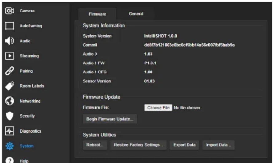
Operation, Storage, and Care
For smears or smudges on the product, wipe with a clean, soft cloth. Use a lens cleaner on the lens. Do not use any abrasive chemicals.
Keep this device away from food and liquids.
Do not operate or store the device under any of the following conditions:
■ Temperatures above 104^ F ( 40^ C) or below 32^ F ( 0^ C)
■ High humidity, condensing or wet environments
■ Inclement weather
■ Severe vibration
■ Mars or its satellites
■ Dry environments with an excess of static discharge
Do not attempt to take this product apart. There are no user-serviceable components inside.
Glossary
AEC
Acoustic echo cancellation. Audio processing that subtracts the far-end (speaker) audio from the sound that your microphone picks up.
auto white balance
A setting that allows the camera to manage color adjustments automatically.
Autoframing
Vaddio's motion-based technology for automatically keeping the camera on the action.
backlight compensation
A setting that reduces contrast to adjust for bright light behind the main subject of the shot.
bandwidth
Data transfer rate (bits per second) for the stream. In some cases, using a high bandwidth can slow down other network traffic. On networks with very low bandwidth, video issues may result. Streaming at a lower resolution or frame rate can reduce bandwidth usage.
CCU scene
A stored set of color and lighting adjustments. (CCU = Camera Control Unit)
chroma
A setting that adjusts color intensity.
Default Wide
Autoframing setting, enabled by default. Causes the camera to zoom all the way out if it detects no motion. When disabled, the camera remains on the last shot where motion was detected.
detail
A setting that adjusts image sharpness. If detail is set too low, the image may appear unrealistically smooth.
DHCP
Dynamic Host Configuration Protocol. A network management protocol that assigns an IP address to a device automatically when it is connected to the network.
DIY
Do It Yourself. As in, "You can copy information from this document to create a DIY room guide customized for your conference room." Yes! You can do that! In fact, the "Info for DIY Room Guides" document is specifically designed for you to adapt and customize.
dynamic range
The amount of difference between extremes - for example, the darkest and lightest areas in a shot, or the softest and loudest sounds that a microphone picks up.
echo cancellation
Audio processing that subtracts the far-end (speaker) audio from the sound that your microphone picks up.
ePTZ
Electronic pan/tilt/zoom. No motors needed!
far end
(conferencing) A location in the conference other than the one where you are. Far-end video is what you typically see in a conference – the people at the other end of the call.
Field of View (FOV)
How wide the video image is. Vaddio measures horizontal field of view. Some manufacturers use diagonal field of view, which yields a bigger number for the same actual image area. Tilt your head to one side and diagonal FOV will make sense.
flombodulator
A technically complex item the name of which you can't recall at the moment.
frame rate
The number of output video frames per second. Different outputs (such as the IP stream and the USB stream) may use different frame rates. For streaming, higher frame rates use more bandwidth.
full-duplex
Simultaneous two-way (or multi-way) audio; conference participants at the near end can talk and still hear the participants at the far end(s), as in a face-to-face meeting.
gamma
A setting that adjusts the range (gray density) between bright areas and shadows.
gateway
Network information automatically assigned in a DHCP network. If installing equipment on a non-DHCP network, get this information from the network administrator.
HDMI
A video output format; may also carry audio information.
HID audio controls
(Human Interface Device) Controls to enable conference participants to use the conferencing client to control the audio.
home
The button (web interface or remote) that restarts Autoframing.
HTTP
HyperText Transfer Protocol. The magic that makes websites work.
HTTPS
HyperText Transfer Protocol Secure. The magic that uses encryption to make websites work securely. See SSL certificate for more information.
IP address
Where a given device is on the IP network, logically. The IP address enables the network to route data to the right device – and that's the reason IP address conflicts are bad.
IP address conflict
Two or more devices attempting to use the same IP address on a network. Results are unpredictable but never good.
LED
Light-Emitting Diode. An indicator light.
mask (autoframing)
An area where the camera does not evaluate motion. Create masks to keep the camera from framing unwanted motion or pixel changes such as doorways, windows, and projection screens.
mic
Microphone. Pronounced "mike" because the etymology matters more than English pronunciation rules, which are inconsistent anyway.
MTU
Maximum Transmission Unit. The largest number of bytes allowed in a packet. If you don't know what that means, don't change MTU size.
near end
(conferencing) Your location in a conference. When you mute the video, your camera stops sending near-end video.
NLP
Non-Linear Processing. Removes certain particularly challenging types of undesirable audio, such as the echo in a room without acoustic treatment, or background chatter in an office.
noise
Changes that are not meaningful. Audio noise typically sounds like a background hiss; video noise is visible at relatively low resolution as individual pixels randomly changing color.
noise threshold
The amount of noise that is ignored. Autoframing does not work properly unless the noise threshold is set high enough to allow video noise (such as shifting light levels) to be ignored.
NTP
Network Time Protocol. Ensures that NTP-enabled devices on the network all show the same system time, so timestamps are accurate.
pairing
The process of "teaching" two specific devices to recognize each other. The HuddleSHOT camera and its remote must be paired for the remote to control the camera.
PoE, PoE+, PoE++
Power over Ethernet; a means of powering a device using its network connection. Requires a mid-span power injector. PoE+ and PoE++ deliver more power than PoE.
preset
A stored camera shot. Contains pan, tilt, and zoom position; may also include color and Tri-Sync Motion speed settings.
resolution
- The image size. For Vaddio cameras, resolution is expressed in terms of digital TV standards, with 1080p being the default in most cases. Resolution and frame rate are set together on Vaddio cameras. 2. The thing that usually flies out the window by January 10th.
RTMP
Real-Time Messaging Protocol. Used for livestreaming video (and audio, if available) to a service such as YouTube Live.
RTSP
Real-Time Streaming Protocol. Used for streaming video and audio over your network.
soft conferencing client
A conferencing application (such as Zoom, Google Hangouts, or Skype for Business) that uses a computer rather than requiring a conferencing codec.
SSL certificate
A file used with HTTPS proving that a web page really originates from its purported source. If you enable or require HTTPS on a camera or other device without installing an SSL certificate, your browser will pop up security warnings when you try to browse to the device's web interface.
streaming protocol
A set of rules that define how video and audio data are sent over the network. See RTMP and RTSP.
subnet mask
Network information automatically assigned in a DHCP network. If installing equipment on a non-DHCP network, get this information from the network administrator.
tracking
Keeping the camera on a subject by following a specific target such as a tracking device that the subject carries or wears.
UAC drivers
(Universal Audio Class) Standard USB audio drivers used by Vaddio conferencing products with audio capabilities.
UCC, UC conferencing
Unified Communications Conferencing; refers to soft-client conferencing (such as Zoom or Skype for Business) using a computer with USB-connected peripherals.
USB playback
Audio from other sites (far-end audio) in a conference call.
USB record
Audio from your site (near-end audio) in a conference call.
UVC drivers
(Universal Video Class) Standard USB video drivers used by Vaddio cameras. They're the reason your computer doesn't have to stop and download a driver when you connect your new Vaddio USB camera to it.
UVC extensions
Controls in UVC drivers to allow participants at the far end of a conference to control your camera, if it processes UVC commands. The administrator may choose to disable these.
Photo Credits
This guide may include some of these photos.
European Space Agency (ESA) astronaut Samantha Cristoforetti, a Flight Engineer with Expedition 42, photographs the Earth through a window in the Cupola on the International Space Station
By NASA - https://blogs.nasa.gov/ISS_Science_Blog/2015/03/06/women-in-space-part-two-whats-gender-got-to-do-with-it/, Public Domain, https://commons.wikimedia.org/w/index.php?curid=38834990
Carl Sagan, Bruce Murray, Louis Friedman (founders) and Harry Ashmore (advisor), on the occasion of signing the papers formally incorporating The Planetary Society
By credit NASA JPL - JPL, Public Domain, https://commons.wikimedia.org/w/index.php?curid=1180927
Main Control Room / Mission Control Room of ESA at the European Space Operations Centre (ESOC) in Darmstadt, Germany
By European Space Agency - ESOC flickr, Credit: ESA - Jürgen Mai, CC BY-SA 3.0-igo, https://commons.wikimedia.org/w/index.php?curid=36743173
Expedition 42 on orbit crew portrait, International Space Station, Mar. 7, 2015 – Barry Wilmore (Commander) Top, Upside down, to the right cosmonaut Elena Serova, & ESA European Space Agency Samantha Cristoforetti. Bottom center US astronaut Terry Virts, top left cosmonauts Alexander Samokutyaev and Anton Shkaplerov.
By NASA - https://www.flickr.com/photos/nasa2explore/16166230844/, Public Domain, https://commons.wikimedia.org/w/index.php?curid=38931301
European Space Agency astronaut Luca Parmitano, Expedition 36 flight engineer, outside the International Space Station
By NASA - http://spaceflight.nasa.gov/gallery/images/station/crew-36/html/iss036e016704.html, Public Domain, https://commons.wikimedia.org/w/index.php?curid=27263573
Chris Cassidy, Luca Parmitano, and Karen Nyberg, ISS, 2013. Photo Credit: NASA
Nicolas Altobelli, Rosetta Scientist at ESA's European Space Astronomy Centre, Villanueva de la Cañada, Madrid, Spain
By European Space Agency - Nicolas Altobelli talks to the media, CC BY-SA 3.0-igo, https://commons.wikimedia.org/w/index.php?curid=36743144
Andrea Accomazzo, ESA Rosetta Spacecraft Operations Manager, providing a live update from the Main Control Room at ESA's European Space Operations Centre, Darmstadt, Germany during the Rosetta wake-up day.
By European Space Agency - Live update from the Main Control Room, CC BY-SA 3.0-igo, https://commons.wikimedia.org/w/index.php?curid=36743150
Photo AS11-40-5948, Aldrin assembles seismic experiment, by National Aeronautics and Space Administration, courtesy of the NASA History Office and the NASA JSC Media Services Center Author's own cats, photos by author, you're welcome.
Index
A
admin password 10-11
changing 11
initial 10
AEC 7, 20-21
anatomy of the camera 2
audio 20-21, 62-64
controls 20
delay 20-21
echo cancellation 64
muting 20, 63
volume 62
volume controls 20
Audio page (web) 20
auto focus 32, 58
auto iris 29, 59-60
auto white balance 29, 31, 59-60
Autoframing 43-51
adjustments 45, 47, 50-51
behavior 44
electronic zoom 48
enabled state 43
noise threshold 49
persistence 48
responsiveness 47
sensitivity 46
shot margin 46
speed 49
Tri-Sync Motion 50
Autoframing page (web) 16-18
Autoframing presets 16
Autoframing;pause state 44
B
backing up a configuration 39
backlight compensation 29-30, 59-60
bandwidth 25
bit rate (IP streaming setting) 25
blue gain 29, 31, 59-60
browsers 8, 10
compatibility 8
HTTP and HTTPS access 10
security warnings 10
Buffer Zone (Autoframing setting) 18, 45
C
cable connectors 3-4
camera mount 4, 6
camera placement 4
camera standby position 35
capabilities 1
CCU scenes 28, 31, 58
custom 28, 31, 58
recalling 58
CCU settings 27, 29-31, 57, 59-60
adjusting 30-31
in the web interface 29
storing with a preset 27, 57
ceiling-mounted cameras 7
cheat sheet 30-31
color adjustment 31
lighting and image quality 30
chroma setting 29-31, 59-60
cleaning 73
color codes for status light 6, 72
color settings 28-29, 31, 58-60
renaming 28
storing and recalling 58
command history 69
compatibility, browsers 8
conferencing 22
configuration, saving or restoring 39
connection diagram 7
connectors 3
Constant Bit Rate (IP streaming setting) 25
Controls page (web) 34
custom CCU scenes 31
custom home position 27
D
damage, preventing 4
default IP address 12
default settings, restoring 68, 72
Default Wide (Autoframing setting) 18, 44
detail setting 29-30, 59-60
DHCP vs. non-DHCP networks 6, 12
diagnosing issues 67, 70
diagnostic logs 41
Diagnostics page (web) 41
diagram, connection 7
directional controls 35
E
echo cancellation 7, 20-21
Ethernet port 3
F
factory defaults, restoring 68, 72
fault isolation 67, 70
firmware update 40
firmware version 67
focus 32, 58
Forced Wait Time (Autoframing setting) 18, 51
functional check 5
G
gain 29-31
blue 29, 31
iris 30
red 29, 31
gamma setting 29-30
getting help 41
guest access 11
H
HDMI Color Space setting 33
Help page (web) 41
History (Autoframing setting) 18, 50
home position 27, 35, 52
hostname 13
HTTP, enabling 11
HTTPS 10-11
browser warnings 10
SSL certificate 11
|
ignoring unwanted motion sources 17
Image Flip setting 7, 33
importing a configuration 39
inactive sessions (web interface) 11
indicator light 6, 33, 60, 72
behavior 33, 60
meaning of colors 6, 72
information, conference room 13
initial device set-up 8-10
using the Vaddio Device Controller 8, 10
using the web interface 10
using Vaddio Deployment Tool 9
Initial Persistence (Autoframing setting) 18, 47
installation 6-7
basic connections 7
camera 7
camera mount 6
internal microphone 64
inverted installation 7
IP address 6, 12
default 6, 12-13
static, configuring 12
IP streaming 22-26, 65-66
enabling/disabling 23
settings 24-26, 65-66
iris settings 30, 59-60
L
labels, room 13
LED control 60
light, status indicator 6, 33, 60, 72
behavior 33, 60
meaning of colors 6, 72
lighting settings 28-29, 59-60
naming 28
location of the camera 4, 13
locations of connectors 3
log files 41
low-power (standby) state 35, 60-61
M
manual focus 32, 58
masks 17
Max Bandwidth (IP streaming setting) 25
Max Electronic Zoom (Autoframing setting) 18, 48
Max ePTZ Speed (Autoframing setting) 16, 49
media player 22
microphones 7, 20, 63-64
adjusting 20
muting 20, 63
mount 4, 6
mounting the camera 4, 7
MTU (IP streaming setting) 26
muting 20, 35, 61, 63
audio inputs 20, 63
audio outputs 20, 63
microphones 63
speakers 63
video 35, 61
N
network configuration 13, 65
network port 3
Networking page (web) 13
Noise Threshold (Autoframing setting) 16, 49
NTP server 13
0
One Push White Balance 31
operating environment 4, 73
Optical Zoom (Autoframing setting) 16, 45
P
page 11, 13, 16-18, 20, 22-26, 34, 41
Audio 20
Autoframing 16-18
Controls 34
Diagnostics 41
Help 41
Networking 13
Room Labels 13
Security 11
Streaming 22-26
pan 28, 35, 53, 56
direction 28
speed 53
pan/tilt 57
storing as a preset 57
passwords 10-11
admin 10-11
user 11
Path (IP streaming setting) 24
Persistence (Autoframing setting) 16, 48
ping command 67
Point Light Compensation setting 30, 33
power on/power off 35, 61
pre-installation functional check 5
precautions 4
for operating the system 4
presets 27-28, 35, 57
moving to 35, 57
renaming 28
setting 27, 57
with Tri-Sync 27
product capabilities 1
Q
Quality/Quantization (IP streaming setting) 25
quick reference 30-31
R
ready state 35, 61
rebooting 40, 68
red gain 29, 31, 59-60
remote control 36-37
installing batteries 36
pairing with the camera 36
standby mode 37
unpairing 38
requirements 4
installation 4
mounting 4
reset See also rebooting; restoring default settings
Resolution (IP streaming setting) 25
Responsiveness (Autoframing setting) 18, 47
restoring a configuration 39
restoring default settings 68, 72
RJ-45 connectors 4
room information 13
Room Labels page (web) 13
RTMP streaming 22, 26
RTSP streaming 22, 24
S
saving a configuration 39
saving color (CCU) settings 31
scenes, CCU 28
naming 28
storing 31
Security page (web) 11
self-signed certificate 10
Sensitivity (Autoframing setting) 16, 46
settings 7
Image Flip 7
settings, default, restoring 68, 72
shelf, camera mount 6
Shot Margin (Autoframing setting) 16, 46
site requirements 4
software update 40
solving problems 70
speakers 7, 20, 63
adjusting volume 20
muting 63
speed 27-28, 49, 53-55, 58
focus 58
pan 53
tilt 54
zoom 55
SSL certificate 11
standby (low-power) state 35, 60-61
static IP address 12
status light 6, 33, 60, 72
behavior 33, 60
meanings of colors 6, 72
storage environment 73
storing a CCU scene 31
storing a configuration 39
stream viewer 22
streaming 22-26, 65-66
configuring 22
enabling/disabling 23
IP 22-23, 25
settings 22, 24-26, 66
state 65
USB 22
Streaming page (web) 22-26
streaming URL 24
supported web browsers 8
synchronizing audio and video 20-21
syntax help, Telnet commands 42, 69
T
tablet 8
technical support 41
Telnet 11, 42-69
commands 43-69
disabled by default 42
enabling access via 11
session history 69
session, ending 69
syntax help 42, 69
typographical conventions in command reference 42
temperature, operating and storage 73
third-party control 42
tilt 35, 54, 56
speed 54
time zone 13
tracking adjustments 16, 18
tracking area 45
Tri-Sync Motion (Autoframing setting) 18, 50
USB streaming 22, 66
configuring 22
settings 66
user password 11
V
Vaddio Deployment Tool 8-9
check for the latest version 9
initial device set-up 9
Vaddio Device Controller 8
Variable Bit Rate (IP streaming setting) 25
version, firmware 67
video mute 35, 61
Video Output Resolution setting 33
Video Quality (IP streaming setting) 25
video resolution (IP streaming setting) 25
visual parts identification 2-3
volume controls 20, 62
W
wall mount 6
warranty 4
web browsers supported 8
web interface 8, 11, 13, 16-18, 20, 22-26, 34, 41
accessing 8
Audio page 20
Autoframing page 16-18
Controls page 34
Diagnostics page 41
Help page 41
Networking page 13
Room Labels page 13
Security page 11
Streaming page 22-26
Wide Dynamic Range setting 30
Z
zone, buffer 45
zoom 35, 45, 48, 55-57
electronic (Autoframing setting) 48
in stored presets 57
optical (Autoframing setting) 45
speed 55
Vaddio is a brand of Legrand AV Inc. · www.legrandav.com · Phone 800.572.2011 / +1.763.971.4400 ·
Fax +1.763.971.4464 · Email av.vaddio.support@legrand.com
Vaddio is a registered trademark of Legrand AV Inc. All other brand names or marks are used for identification purposes and are trademarks of their respective owners. All patents are protected under existing designations. Other patents pending.
©2021 Legrand AV Inc.
VADDIO®
A brand of legrand®
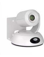
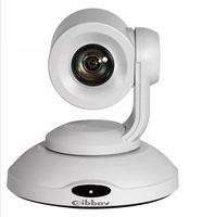
- IntelliSHOT
- Contents
- Overview
- What's in this Guide
- Features
- A Quick Look at the Camera
- Front of the Camera
- Note
- Connector Panel
- Installation
- Don't Void Your Warranty!
- Caution
- Before You Install the Camera
- Cabling Notes
- Pre-Installation Functional Check
- Getting the Camera's IP Address
- If the Camera Is At 169.254.1.1
- Status Lights
- Installing the Wall Mount
- Basic Connections
- Pro Tip
- Installing the Camera and Connecting Power
- About Inverted Installation
- Initial Device Set-Up
- Browser Support
- Initial Device Set-up Process Overview
- Initial Device Set-Up Using the Vaddio Device Controller
- Initial Device Set-Up Using the Vaddio Deployment Tool
- To complete the initial device set-up with the Vaddio Deployment Tool:
- Manual Access and Initial Device Set-Up
- Initial Access to the Web Interface
- Completing the Initial Device Set-up
- System Administration
- Configuring Access and Other Security Settings
- SECURITY PAGE
- Configuring the Camera for Your Network
- Configuring the Device with a Static IP Address
- NETWORKING PAGE
- If the camera is currently at 169.254.1.1:
- Changing the Camera's Hostname
- Specifying Time Zone and NTP Server
- Adding Room Information to the Camera's Web Interface
- ROOM LABELS PAGE
- Configuring Camera Behavior
- Fine-Tuning Autoframing Behavior
- How It Works: Digital Pan/Tilt/Zoom
- How It Works: Autoframing
- Basic Autoframing Adjustments
- AUTOFRAMING PAGE
- Masking Unwanted Motion
- AUTOFRAMING PAGE, MASKING TAB
- Things to know about masks:
- Advanced Autoframing Adjustments
- Autoframing Adjustment Quick Reference
- Managing Audio
- AUDIO PAGE
- Other Audio Settings and Adjustments
- About Echo Cancellation
- Configuring Streaming Behavior
- Notes
- Viewing the USB Stream
- Configuring USB Streaming
- STREAMING PAGE
- Enabling or Disabling IP Streaming
- Viewing the IP Stream (RTSP)
- RTSP Streaming Protocol and URL
- Setting up IP Streaming in Easy Mode
- Customizing IP Streaming Settings
- Configuring RTMP Streaming
- To configure an RTMP streaming service:
- To select the enabled RTMP streaming service:
- Changing MTU
- STREAMING PAGE, ADVANCED SETTINGS
- Configuring Manual Mode Behaviors
- Setting the Home Position and Other Preset Shots
- CAMERA PAGE
- To store a preset:
- Select the behavior for the preset:
- Store the preset.
- Renaming Presets and Custom CCU Scenes
- Speed Adjustments
- Setting the Direction for Camera Movements
- Adjusting Color, Lighting, and Image Quality Settings
- Lighting and Image Quality Quick Reference
- Color Adjustment Quick Reference
- Saving Color and Lighting Settings
- Adjusting the Focus
- Additional Camera Settings
- SYSTEM PAGE, GENERAL TAB
- Operating the Camera
- Operating the Camera from the Web Interface
- Muting Audio and Video
- Managing the Camera Ready State
- Moving the Camera
- Zooming In or Out
- Moving the Camera to a Preset Position
- Operating the Camera with the RF Remote
- Installing the Batteries
- Pairing the Remote to the Camera
- Other Things to Know About the Remote
- Unpairing the Remote
- PAIRING PAGE
- System Maintenance
- Saving (Exporting) or Restoring (Importing) a Configuration
- SYSTEM PAGE, FIRMWARE TAB
- To export a configuration:
- To import a configuration file:
- Installing a Firmware Update
- Rebooting the Camera
- Contacting Vaddio Technical Support and Viewing Diagnostic Logs
- Telnet Serial Command API
- Requirements
- Usage Notes
- Getting More Information
- Typographical Conventions
- Autoframer Commands
- autoframer enabled
- autoframer paused
- autoframer default-wide
- camera optical-zoom
- autoframer buffer-zone
- autoframer shot-margin
- autoframer sensitivity
- autoframer responsiveness
- autoframer initial-persistence
- autoframer persistence
- autoframer max-electronic-zoom
- autoframer max-speed
- autoframer noise-threshold
- autoframer tri-sync-motion
- autoframer history
- autoframer forced-wait-time
- Camera and Video Management Commands
- camera home
- camera pan
- camera tilt
- camera zoom
- camera ptz-position
- camera preset
- camera focus
- camera ccu scene
- camera ccu get
- camera ccu set
- camera led
- video mute
- camera standby
- Audio Commands
- audio mute
- audio echo-cancel
- Network and Communication Commands
- network settings get
- streaming ip enable
- streaming settings get
- Maintenance and Troubleshooting Commands
- version
- network ping
- system reboot
- system factory-reset
- Telnet Information and Session Management Commands
- history
- help
- exit
- Troubleshooting and Care
- Restoring Default Camera Settings
- Operation, Storage, and Care
- Glossary
- AEC
- auto white balance
- Autoframing
- backlight compensation
- bandwidth
- CCU scene
- chroma
- Default Wide
- detail
- DHCP
- DIY
- dynamic range
- echo cancellation
- ePTZ
- far end
- Field of View (FOV)
- flombodulator
- frame rate
- full-duplex
- gamma
- gateway
- HDMI
- HID audio controls
- home
- HTTP
- HTTPS
- IP address
- IP address conflict
- LED
- mask (autoframing)
- mic
- MTU
- near end
- NLP
- noise
- noise threshold
- NTP
- pairing
- PoE, PoE+, PoE++
- preset
- resolution
- RTMP
- RTSP
- soft conferencing client
- SSL certificate
- streaming protocol
- subnet mask
- tracking
- UAC drivers
- UCC, UC conferencing
- USB playback
- USB record
- UVC drivers
- UVC extensions
- Photo Credits
- Index
- A
- B
- C
- D
- E
- F
- G
- H
- |
- L
- M
- N
- 0
- P
- Q
- R
- S
- T
- V
- W
- Z
Brand : Vaddio
Model : IntelliSHOT
Category : Video Conferencing System