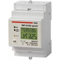
Energy-400 Bi PWR - Measurement Vemer - Free user manual and instructions
Find the device manual for free Energy-400 Bi PWR Vemer in PDF.


| Product Type | Three-phase Bidirectional Energy Meter |
| Brand | Vemer |
| Model | Energy-400 Bi PWR |
| Dimensions (approx.) | 3 DIN modules (160.5 x 90 x 60 mm) |
| Weight (approx.) | 200 g |
| Power Supply | 3x220-400V AC -15% +10%, 50/60 Hz |
| Input Current (basic) | 6 A |
| Starting Current | 0.01 A |
| Accuracy Class | B |
| Pulse Output | Remote reading, 100 ms duration, 9-24V DC, max 20 mA |
| LED Indication | Red flashing (1.5 imp/kWh) for both withdrawn and injected energy |
| Operating Temperature | -10°C to +45°C |
| Operating Humidity | 10% to 95% (non-condensing) |
| Storage Temperature | -25°C to +70°C |
| Protection Degree | IP20 (indoor use) |
| Mounting | DIN rail, 3 modules |
| Functions | Measures active energy withdrawn and injected, bidirectional, MID compliant, backlighting, connection check |
| Safety | Install by qualified operator; disconnect power before servicing |
| Standards Compliance | MID (2004/22/EC), EN 61010-1, EN 50470 series |
Frequently Asked Questions - Energy-400 Bi PWR Vemer
User questions about Energy-400 Bi PWR Vemer
0 question about this device. Answer the ones you know or ask your own.
Ask a new question about this device
Download the instructions for your Measurement in PDF format for free! Find your manual Energy-400 Bi PWR - Vemer and take your electronic device back in hand. On this page are published all the documents necessary for the use of your device. Energy-400 Bi PWR by Vemer.
USER MANUAL Energy-400 Bi PWR Vemer

INSTALLATION
SETTING THE AMPEROMETRIC TRANSFORMATION RATIO
The default settings have a transformation ratio CT 5/5A.
To change the transformation ratio.
I press the "Self" key and power the counter
- when the display shows the screen of transformation ratio Pr 18 you
can release the key
3 press the "Self" key for a long time until the value of the transformation
ratio begins to flash
- set the transformation ratio by pressing the "Sol" key. The exit from
the menu occurs automatically after approximately 4 seconds without
pressing any key.
The variation of the transformation ratio causes a distortion of the counter
The value of the counters remain unchanged at the value reached until that
moment

Settable CT values
- from 5/5 A to 2005 A by increments of 5
from 2005 A to 10005 A, by increments of 53
from 10005 A to 25005 A, by increments of 100

OPERATION
User manual BIDIRECTIONAL ENERGY METER Read all the instructions carefully
The Energy-100 DI PWR static energy meter is an appliance to read active
energy both withdrawn and injected in three-phase 400Vac systems
It is designed to operate in environments with category of overvoltage ill and
pollution degree 2 according to EN 61010-1 standard
The energy meter Energy-400 B: PNR is in compliance with MID (2004/22/CE) and
It's suitable for use in mechanical environment of type fill and in electromagnetic
one of type E2.
SAFETY WARNINGS
To guarantee correct installation, proceed as follows:
- The appliance should be installed by a qualified operator.
1) The appliance should be installed in a pipe in such a way as in a manner that
21 The appliance should be installed in a sense in such a way as to guarantee that the terminants are inappropriate after filling.
the criminals are inaccessible and having 20. A protection device required now warranty should be installed in the electrons.
3) A protection device against non-currents should be installed in the electrical system. Version of the circuit motor
system, upstream of the energy meter
4) Connect the Instrument as shown in the alongside diagrams
5) Before touching the connector terminals make sure that the wires to be con
nected or already connected to the instrument are not live
6) Do not power or connect the device if any part of it is damaged
71 The device must be installed and activated in compliance with current electric
systems standards.
VE754600 Energy-100 Bi PNR Three-phase bidirectional energy meter
TECHNICAL SPECIFICATIONS
• Power supply: 3x220 (400V AC) -15% = +10% 50/90Hz
• Maximum power consumption:
-voltage circuits: 25/60
current circuits 2.5 HA
- current circulation: 25 MW - Input current I: 6A
- Platin channel 1: 0.01A
- Starting EBITDA, C. 01/06 - Transition cost, C. 07/06
- Transduction, v. 0.254
- KENTHIN GARTINI, en 0.05%
• Maximum current
• Amperometric connection through external CT data
- Resolution:
- total energy: 100Wh
- perdaal energy: 0.01KW (autogcalcd)
- Pulse output: optimized for remote reading of the withdrawn energy counting
- pulse duration: 100ms ± 15%
- pulse voltage: 9 ÷ 24V DC ± 10%
- maximum output current: 20 mA
• Signaling led
- 2017年1月1日
- yellow: injected enzyme inhibitor, production
- red flashing with frequency 1.5 kWh, both injected and withdrawn
• Class Index: B
- Operating temperature: -10 = -45 °C
• Operating humidity: 10% ± 95% preceding
- Operating margin: 10.5% + 30.3% (non-GAAP)
■ Shcrem brevemius: 26.4% - 70.9%
- Storage temperature 25 ± 70 °C - Capacitors: 2 DIP module
• Container: 3 DIN modules • Protection degree: 1670137
- Protocol degree: IP204-5108 the normal
CN

flowchart
graph LR
    A["开始"] --> B["63 150."]
    B --> C["63 150."]
    C --> D["PF L095 17623."]
    D --> E["00 0562 39506."]
    E --> F["00 0562 39506."]
    F --> G["结束"]
1 Display of withdrawn energy (consumed)
Total withdrawn energy (7 digits) resolution 1 kWh
Partial withdrawn energy (5 dicibio), resolution 0.01kWh (autocasei)
From this screen, press the "Self" key for a long time to activate the check of
The connections (see "Checking the connections")

2 Display of total withdrawn energy (consumed)
Total withdrawn energy (7 digits), resolution 1kWh. The counter can not be
rest. From this screen, press the "Sel" key for a long time to access the
visualization of the set CT.

3 Display of partial withdrawn energy (consumed)
Partial withdrawn energy (5 clatts), resolution 0.01 kWh. The counter can not be
reset. From this screen press the "Sell" key for a long time to reset the counter.

4 Display of power and power factor
Power factor (PF) and withdrawn instantaneous power (▶) or injected (<).
Display of System sizes Ⅱ for inductive power factor C for capacitive type
power factor.
From this screen, press the "Sel" key in across the selling of the
backlighting see "Backlighting management".

- Display of injected energy (produced)
Intra-injected enzyme (c) cells, resolution 1 kV/h
Partial injected energy (5 dicit), resolution 0.01xMn (supercalou
From this screen, move the shelf key for a long time, to activate the electric
From this school, press the "Set Key for a long unit of the connections use 'Checking the connections'
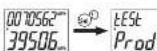
6 Display of total injected energy (produced)
Total injected energy (7 digits), resolution 1kWh. The counter can not be reset.

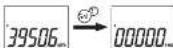
7 Display of partial injected energy (produced)
Partial injected energy (5 digits), resolution 0.01kWh. The counter can not be
reset. From this screen, press the "Sel" key to reset the counter.
G
Backlighting management
To access the "Backlighting management"
• from the screen "4. Design of power and power factor".
press the "Self" key for a long time

Choose On to have the backlighting always active or a 40E (default setting) to have the backlighting active within 30 seconds after the pressure of the key.
Checking the connections
To access "Checking the connections"
- from the screen 31. Display of valbutrow engine for
• from the screen "5. Display of injected energy"
where the "Self" key for a long time

The counter indicates the following errors during the connections:
U-L-CCB Connection error of voltage input: the sequence of L1-L2-L3 phase
out 37 is not respected
Error
LIF
4.1.2 Connection error of voltage input on two-phase in this case 1
Golfie
C
CFFOR
- 0.43. No Power selection error, zero power is measured (zero willange or
no ^p 13 , in the case of an active path in the voltage current in one of the phases in this case L1 and L30
Error
Connection error of current inputs on two phases (in this case L2 and L3)
LDPES
Error
No error condition detected.
no in this case the counter will display on. Error for two seconds then it
Fccoc will return to the Display of energy I or S
In case of error message, to restore the correct operation, you must turn all the counter.
check that the connections of the voltage and currents mirror the diagram of this manual
and then look on the melo asan.
Important, there are combinations of errors that compensate each other. In such cases it
is not possible to report the error and the counter measures an incorrect energy value.
4-2/17
REFERENCE STANDARS
Conformity to European Community directives:
201435E11 (out of 2016)
2004/22/EC (M)
Is declared accr
is declared according to the 150MW solar cells.
EN 61010-1, EN 50470-9
EN 50470-0, EN 50470-3


Brand : Vemer
Model : Energy-400 Bi PWR
Category : Measurement