
Energy-400 M PWRi - Measurement Vemer - Free user manual and instructions
Find the device manual for free Energy-400 M PWRi Vemer in PDF.


| Product Type | Power Analyzer / Energy Meter |
| Brand | Vemer |
| Model | Energy-400 M PWRi |
| Measurement Functions | Voltage, Current, Active/Reactive/Apparent Power, Power Factor, Frequency, Active/Reactive Energy |
| Display | Backlit LCD, 4 lines of 16 characters |
| Dimensions (W x H x D) | 96 x 96 x 60 mm (panel cutout: 92 x 92 mm) |
| Weight | Approx. 200 g |
| Power Supply | 100-240 VAC, 50/60 Hz or 24 VDC (optional) |
| Communication Interfaces | RS485 Modbus RTU (optional Ethernet) |
| Inputs | 3-phase voltage (up to 400 V L-L), 3-phase current via external CTs (5A secondary) |
| Accuracy | Class 0.5S for energy (IEC 62053-22) |
| Operating Temperature | -10°C to +55°C |
| Storage Temperature | -20°C to +70°C |
| Protection Degree | IP40 front panel, IP20 rear |
| Installation | Panel mount, flush |
| Compliance | CE, IEC 61010-1 |
| Maintenance | No user-serviceable parts; cleaning with dry cloth; periodic calibration recommended every 5 years |
| Safety | Use insulated tools; disconnect power before wiring; ensure proper grounding |
| Spare Parts & Repairability | Contact Vemer support for replacement parts; device is not field-repairable, return for service |
Frequently Asked Questions - Energy-400 M PWRi Vemer
User questions about Energy-400 M PWRi Vemer
0 question about this device. Answer the ones you know or ask your own.
Ask a new question about this device
Download the instructions for your Measurement in PDF format for free! Find your manual Energy-400 M PWRi - Vemer and take your electronic device back in hand. On this page are published all the documents necessary for the use of your device. Energy-400 M PWRi by Vemer.
USER MANUAL Energy-400 M PWRi Vemer
3 CT connection WITH or WITHOUT neutral (3 or 4 wires)
![graph TD A["Component 3"] --> B["Component 5"] C["Component 7"] --> D["Component 9"] E["Component 10"] --> F["Component 11"] G["Component 13"] --> H["Component 14"] I["Component 15"] --> J["Component 16"] K["Component 17"] --> L["Component 18"] M["Component 19"] --> N["Output"] O["Input"] --> P["Pul…](/content/2026/05/977457/images/2636d6a4fec1de90f951f5666651b6ae9e06455d298c8db078f253b17bcabb8e.jpg)
Instrument description (C)
USER MANUAL
THREE-PHASE ACTIVE ENERGY METER
Read all instructions carefully
■ The energy meter ENERGY-400 M PWRI is an electronic static device to read active energy in three-phase systems.
The energy meter ENERGY-400 M PWRI is in compliance with MID (2004/22/CE) and it's suitable for use in mechanical environment of type M1 and in electromagnetic one of type E2.
SAFETY WARNINGS
To guarantee correct installation, proceed as follows:
1) The appliance should be installed by qualified operator
2) The appliance should be installed in a panel in such a way as to guarantee that the terminals are inaccessible after fitting
3) The appliance should be installed in a panel in such a way to guarantee a protection IP51 in accordance with the standard CEI EN 60529.
4) A protection device against over-currents should be installed in the electrical system, upstream of the energy meter.
5) Connect the instrument as shown in the alongside diagrams.
6) Before touching the connector terminals make sure that the wires to be connected or already connected to the instrument are not live.
7) Touch the dip-switches only when the instrument is not powered.
8) Do not power or connect the instrument if any part of it is damaged.
9) The instrument must be installed and activated in compliance with current electric system standards.
Code
Model
Description
Three-phase energy meter 400 VAC MID
TECHNICAL SPECIFICATIONS
• Power supply:
3x230 V AC phase-neutral (400VAC phase-phase) (-15% ÷ +10%)
• Frequency: 50 Hz
• Start-up current: Id=15 mA
• Minimum current: Imin = 0.1 A
• Reference current:
• Transitional current: Iα=0.25A
• Maximum current: Imax=6A
• Maximum power consumption:
- voltage circuits < 2.5 VA
- current circuits < 2.5 VA
• Meter constant: 4 Imp./kWh
• Voltage inputs: input impedance = 2 MΩ
• Current inputs: coils with insulation between primary and secondary
• Optoinsulated impulse output:
- weight impulse: 1 kWh/impulse
- Impulse duration < 100 ms ± 15%
- voltage: 9÷24 V DC ± 10%
- maximum output current: 20 mA
• Insulation:
- reinforced between impulse output and other terminals
- reinforced between terminals and accessible parts after installation
• CT available: 5-10-25-50-75-100-125-150-200-250-300-400-500-600-800-1000/5A
• Operating temperature: -10 °C ÷ +55 °C
• Storage temperature: -25°C ÷ + 70 °C
• Relative humidity: 10÷90% non condensing
• Class index: class A
- Container: 4 modules DIN
• Protection level: IP20 / IP40 on the front
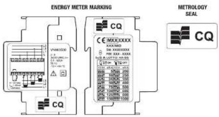
Marking (D)
INSTRUMENT DESCRIPTION
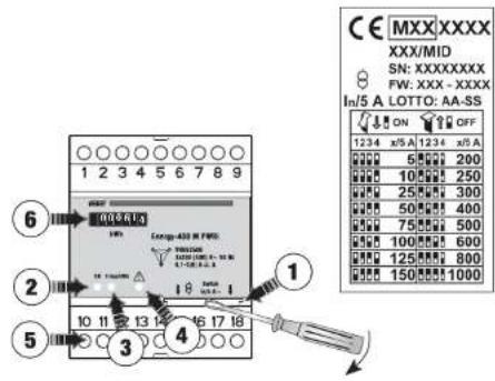
① Dip-switch for CT setting
② Green warning light: lights up to indicate power on
③ Red warning light: flashes to indicate that the instrument is metering energy (4 flashes / kWh)
② Yellow warning light: when lit instrument detects 1/4 kWh negative (probable incorrect entry) and remains lit until 1/4 kWh positive is detected Check the insertion of CT: connect L1, L2, L3 from power panel to P1 of CT and connect P2 of CT to the load
③ Impulse output Optoinsulated
⑤ Electro-mechanical impulse counter: resolution 1 kWh
GUIDE TO INSTALLATION
1) Before installing the instrument, select the required transformation ratio, as shown in panel (C).
2) The CT secondaries may be connected to earth.
3) The instrument should be connected as shown in the panel (B), in accordance with the CT current directions.
4) If the error is to fall within the class limits of the instrument, it is necessary to use the current transformer in its linear operating field.

5) If the instrument is active to power should be switched off to change the CT ratio.
6) In case of changes to the dip-switches with instrument activated, these locks in fault condition with red and green lights always on. In this condition the instrument doesn't count.
To restore the correct operation, reposition the DIP switches in the initial condition or reset the instrument by removing and restoring power.
REFERENCE STANDARDS
Conformity to EU directive:
2004/22/CE (MID)
is declared with reference to the following harmonised standards:
EN 50470-1 and EN 50470-3

Brand : Vemer
Model : Energy-400 M PWRi
Category : Measurement