CC-50 - Radio YAMAHA - Free user manual and instructions
Find the device manual for free CC-50 YAMAHA in PDF.

| Product Type | Portable Radio |
| Brand | Yamaha |
| Model | CC-50 |
| Dimensions (W x H x D) | 300 x 150 x 100 mm |
| Weight | 1.5 kg |
| Power Supply | AC 230V or 4x AA batteries |
| Frequency Bands | AM (MW) and FM |
| Speaker | Built-in, 3 inches |
| Headphone Jack | 3.5 mm stereo |
| Antenna | Telescopic for FM; built-in ferrite for AM |
| Controls | Volume, tuning, band selector, power |
| Indicators | Power LED, tuning dial |
| Cleaning | Wipe with a soft, dry cloth |
| Safety | Avoid moisture and extreme temperatures |
| Spare Parts | Available through Yamaha service centers |
| Repairability | Authorized repair by Yamaha technicians |
Frequently Asked Questions - CC-50 YAMAHA
User questions about CC-50 YAMAHA
0 question about this device. Answer the ones you know or ask your own.
Ask a new question about this device
Download the instructions for your Radio in PDF format for free! Find your manual CC-50 - YAMAHA and take your electronic device back in hand. On this page are published all the documents necessary for the use of your device. CC-50 by YAMAHA.
USER MANUAL CC-50 YAMAHA
This product complies with the radio frequency interference requirements of the Council Directive 82/499/EEC and/or 87/308/EEC.
Thank you for purchasing this YAMAHA product. We hope it will give you many years of trouble-free enjoyment. For the best performance, read this manual carefully. It will guide you in operating your YAMAHA product.
FEATURES
- 35W + 35W (6Ω) RMS Output Power, 0.08% THD, 50–20,000 Hz
• 4-Mode Digital Sound Field Processor (DSP) - Digital Sound Field Effective Even by Listening with Headphones
- Random Access Programmable CD Playback
- Single Track/Entire Disc Repeat Play
• Random-sequence Play
• Automatic Synchronized Recording with CD Playback -
Automatic CD Editing Function for Recording to Tape
-
Double Cassette Tape Deck with Automatic Reversing Function
• 2-Way Speed Dubbing
• Dolby B/C Noise Reduction System
• 40 Station Automatic Preset Tuning - Multi-Use Timer/Sleep Timer
• Active Servo Processing Speaker System (NX-S50) - Remote Control Capability
CONTENTS
Page PRECAUTIONS....2-3
ACTIVE SERVO TECHNOLOGY ....3
NAMES OF CONTROLS, INDICATORS AND
REAR PANEL PARTS....4-6
REMOTE CONTROL TRANSMITTER....7-9
PREPARATION FOR USE 10-11
OPEN/CLOSE THE CONTROL DOOR ....12
TURNING THE POWER ON/OFF TO THIS SYSTEM.....12
SETTING THE CLOCK ....13
SOUND CONTROL....14
Page
DIGITAL SOUND FIELD PROCESSOR (DSP)
CONTROL....14
COMPACT DISC PLAYER OPERATION....15-22
TUNING OPERATION 23-25
TAPE DECK OPERATION 26-29
RECORDING A COMPACT DISC 30-35
OTHER RECORDINGS....36-37
HOW TO USE THE BUILT-IN TIMER....38-41
USING EXTERNAL UNITS....42-43
MAINTENANCE 43
SPECIFICATIONS....44
TROUBLESHOOTING 45
PRECAUTIONS: READ THIS BEFORE OPERATING YOUR UNIT
■ To assure the finest performance, please read this manual carefully. Keep it in a safe place for future reference.
This system is equipped with the newly developed Active Servo Processing Speaker System. It is not designed for use with conventional speakers. Therefore, do not attempt to connect other speakers than the provided speaker system.
- Choose the installation location of this unit carefully. Avoid placing it in direct sunlight or close to a source of heat. Also avoid locations subject to vibration and excessive dust, heat, cold or moisture. Keep it away from sources of hum such as transformers and electric motors.
■ Do not operate this unit upside-down. It may overheat, possibly causing damage.
■ Never open the cabinet. If something drops into the set, contact your dealer.
■ The openings on the cabinet assure proper ventilation of the unit. If these openings are obstructed, the temperature inside the cabinet will rise rapidly and eventually damage the circuits. Therefore, avoid placing objects against these openings and do not install the unit where the flow of air through the ventilation openings could be impeded.
■ Always set the VOLUME control to "0" before starting the audio source play: increase the volume gradually to an appropriate level after the play has been started.
■ When not planning to use this unit for long periods of time (ie., vacation, etc.), disconnect the AC power plug from the wall outlet.
■ Grounding or polarization – Precautions should be taken so that the grounding or polarization of an appliance is not defeated.
■ Do not use force on switches, controls or connection wires. When moving the unit, first disconnect the power plug and the wires connected to other equipment. Never pull the wire itself.
■ Do not attempt to clean the unit with chemical solvents; this might damage the finish. Use a clean, dry cloth.
■ Be sure to read the "TROUBLESHOOTING" section regarding common operating errors before concluding that the unit is faulty.
■ To prevent lightning damage, disconnect the AC power plug and the antenna cable when there is an electrical storm.
■ Do not plug the AC power plug to the wall socket before you finish all connections.
- Never allow metallic items (e.g. screwdrivers, tools, etc.) to come near the cassette deck's record/playback head assembly in this unit. Doing so may not only scratch or damage the head's mirror-smooth finish, it may change the magnetic characteristics of the heads, causing a deterioration in reproduction performance quality.
Although the cassette deck's record/playback heads used in this unit are high quality heads with outstanding reproduction characteristics, they can become dirty through the use of old tapes or from dust accumulation over time. This can have a serious effect on reproduction quality. Clean the heads regularly with one of the commonly available head cleaners or with cleaning solutions.
■ The voltage to be used must be the same as that specified on this unit. Using this product with a higher voltage than that which is specified is dangerous and may result in a fire or other type of accident causing damage. YAMAHA will not be held responsible for any damage resulting from use of this unit with a voltage other than that which is specified.
■ The sound level at a given volume setting depends on a combination of speaker efficiency, location and many other factors. Care should be taken to avoid exposure to sudden high levels of sound, which may occur when turning on the unit with the volume control setting at high, and to continuous high levels of sound.
■ Sudden temperature changes and storage or operation in an extremely humid environment may cause condensation inside the cabinet. Condensation can cause the unit to malfunction. Follow the procedure below to eliminate condensation.
- CD pickup
Leave the power on with no disc in the unit until normal playback is possible (about 1 hour). - Tape head
Leave the power on with no cassette in the unit until normal playback is possible (about 1 hour).
If condensation forms on the tape head, foreign matter may accumulate during use. - Remote control
Wipe off condensation on the transmitter window with a soft cloth before operating the unit.
Note
IMPORTANT
Please record the serial number of this unit in the space below.
Serial No.:
The serial number is located on the rear of the unit.
Retain this Owner's Manual in a safe place for future reference.
WARNING
TO REDUCE THE RISK OF FIRE OR ELECTRIC SHOCK, DO NOT EXPOSE THIS APPLIANCE TO RAIN OR MOISTURE.
CAUTION (FOR CANADA MODEL)
TO PREVENT ELECTRIC SHOCK, MATCH WIDE BLADE OF PLUG TO WIDE SLOT AND FULLY INSERT.
FOR CANADIAN CUSTOMER
THIS DIGITAL APPARATUS DOES NOT EXCEED THE "CLASS B" LIMITS FOR RADIO NOISE EMISSIONS FROM DIGITAL APPARATUS SET OUT IN THE RADIO INTERFERENCE REGULATION OF THE CANADIAN DEPARTMENT OF COMMUNICATION.
NOTE
Please check the copyright laws in your country to record from records, compact discs, radio, etc. Recording of copyright material may infringe copyright laws.
Be sure not to carry or tip the CD player with discs remaining in it.
For U.K. customers
If the socket outlets in the home are not suitable for the plug supplied with this appliance, it should be cut off and an appropriate 3 pin plug fitted. For details, refer to the instructions described below.
Note: The plug severed from the mains lead must be destroyed, as a plug with bared flexible cord is hazardous if engaged in a live socket outlet.
SPECIAL INSTRUCTIONS FOR U.K. MODEL
IMPORTANT:
The wire in the mains lead are coloured in accordance with the following code:
Blue: NEUTRAL
Brown: LIVE
The colours of the wires in the mains lead of this apparatus may not correspond with the coloured markings identifying the terminals in your plug. Proceed as follows: the wire which is coloured BLUE must be connected to the terminal which is marked with the letter N or coloured BLACK. The wire which is coloured BROWN must be connected to the terminal which is marked with the letter L or coloured RED. Making sure that neither core is connected to the earth terminal of the three pin plug.
PRECAUTIONS: READ THIS BEFORE OPERATING YOUR UNIT
WARNING
To reduce the risk of fire or electric shock, do not expose this unit to rain or moisture.
To avoid electrical shock, do not open the cabinet. Refer servicing to qualified personnel only.
CAUTION 1
Use of controls or adjustments or performance of procedures other than those specified herein may result in hazardous radiation exposure.
CAUTION 2
As the laser beam used in this compact disc player is harmful to the eyes, do not attempt to disassemble the cabinet. Refer servicing to qualified personnel only.
CLASS 1 LASER PRODUCT APPAREIL À LASER DE CLASSE 1 PRODUCTO LASER DE CLASE 1
This compact disc player is classified as a CLASS 1 LASER product. The CLASS 1 LASER PRODUCT label is located on the rear exterior. (Europe and U.K. model only)
Laser component in this product is capable of emitting radiation exceeding the limit for Class 1.
Laser Diode Properties
- Material: GaAlAs
• Wavelength: 780nm - Emission Duration: continuous
- Laser Output: max. 44.6μW*
* This output is the value measured at a distance of about 200mm from the objective lens surface on the Optical Pick-up Block.
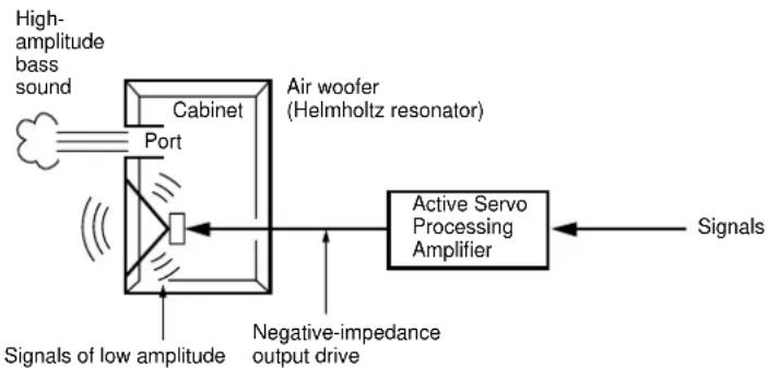
ACTIVE SERVO TECHNOLOGY
flowchart
graph LR
    A["High-amplitude bass sound"] --> B["Cabinet Port"]
    B --> C["Air woofer (Helmholtz resonator)"]
    C --> D["Active Servo Processing Amplifier"]
    D --> E["Signals"]
    B --> F["Signals of low amplitude"]
    F --> G["Negative-impedance output drive"]
The theory of the Active Servo Technology is based upon two major factors, the Helmholtz resonator and negative-impedance drive. Active Servo Processing speakers reproduce the bass frequencies through an "air woofer", which is a small port or opening in the speaker's cabinet. This opening is used instead of, and performs the functions of, a woofer in a conventionally designed speaker system. Thus, signals of low amplitude within the cabinet can, according to the Helmholtz resonance theory, be output from this opening as waves of great amplitude if the design is such that the size of the opening and the volume of the cabinet are in the correct proportion to satisfy a certain ratio. In order to accomplish this, moreover, the amplitudes within the cabinet must be both precise and of sufficient power because these amplitudes must overcome the "load" presented by the air that exists within the cabinet.
Thus it is this problem that is resolved through the employment of a design in which the amplifier functions to supply the signals. If the electrical resistance of the voice coil is reduced to zero, the movement of the speaker unit would become linear with respect to signal voltage, and, to accomplish this, a special negative-impedance output-drive amplifier for subtracting output impedance of the amplifier is used.
By employing negative-impedance drive circuits, the amplifier is able to generate precise, low-amplitude low-frequency waves with superior damping characteristics, and these waves are then radiated from the cabinet opening as high-amplitude signals. The system can, therefore, by employing the negative-impedance output drive amplifier and a speaker cabinet with the Helmholtz resonator, reproduce an extremely wide range of frequencies with amazing sound quality and less distortion.
The features described above are combined to be the fundamental structure of the Active Servo Technology.
For CD Player
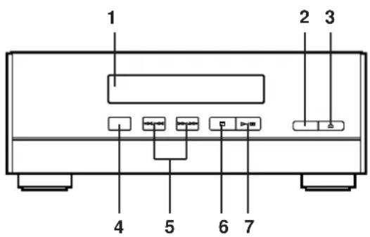
For Receiver
CD Player (CDX-S50)
- Disc Table
- RESUME button
- OPEN/CLOSE Button: △
- RANDOM Play Button
-
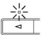
SKIP Buttons: ◀/▶ (SEARCH Buttons: ◀/▶)
-
Stop Button:
-
Play/Pause Button: ➤ ☐
-
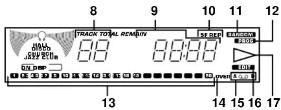
Track Number Indicator
-
Time Display
-
(S, F) REPEAT Indicator
-
RANDOM Play Indicator
-
PROGRAM Indicator
-
Music Calendar Indicator
-
Music Calendar OVER Indicator
-
Tape Side Indicator
-
EDIT Indicator
-
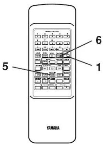
Play Indicator: ▶
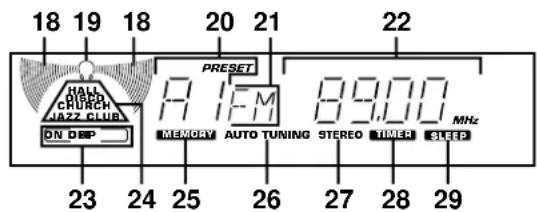
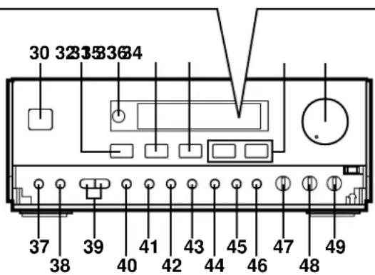
Receiver (RX-S50)
- Effect Level Indicator
- Phones Mode Indicator
- Preset Number Indicator
- Band Indicator
- Station Frequency Indicator
- DSP ON/OFF Indicator
- DSP Mode Indicators
- MEMORY Indicator
- AUTO TUNING Indicator
- STEREO Indicator
- TIMER Set Indicator
-
SLEEP Indicator
-
POWER Switch
-
DSP ON/OFF Selector Button
-
Remote Control Sensor
-
DSP MODE Selector Button
-
SP/PHONES Mode Selector Button
-
INPUT Selector Buttons: ◀ ▶
-
VOLUME Control
-
PHONES Jack
-
DISPLAY Button
-
TUNER PRESET DOWN/UP Buttons
-
A/B/C/D/E (TIMER) Button
-
MEMORY (TIME ADJUST) Button
-
TUNING DOWN (HOUR) Button
-
TUNING UP (MINUTE) Button
-
AUTO/MAN'L (SEC) Button
-
BAND Selector Button
-
AUTO MEMORY (TIMER REC) Button
-
BASS Tone Control
-
TREBLE Tone Control
-
BALANCE Control
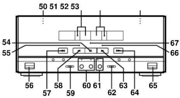
Double Cassette Tape Deck (KXW-S70)
- DECK A Cassette Compartment
- DECK A Select Button and Indicator
- DECK B Select Button and Indicator
- DECK B Cassette Compartment
- Stop Button: □
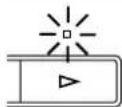
- Play Direction Indicator ( )
- DECK A EJECT Button
- Fast Wind Button:
- Play Button: △
- Reverse Mode Switch
- DUBBING (NORMAL/HIGH) Buttons and Indicators
- REC/PAUSE Button and Indicator
- Dolby NR Switch
- Play Button: ▷
- Fast Wind Button: ▷
- DECK B EJECT Button
- Play Direction Indicator (▶)
- PLAY Indicator
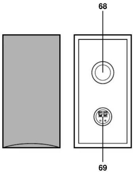
Speakers (NX-S50)
-
YST Port
-
Speaker Terminals
NAMES OF CONTROLS, INDICATORS AND REAR PANEL PARTS
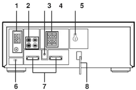
Rear Panel of Receiver
- Antenna Terminals
- INPUT (PHONO and AUX) Terminals
- GND Terminal
- SPEAKERS Terminals
- VOLTAGE SELECTOR (General model only)
- FREQUENCY STEP Switch (General model only)
- System Control Sockets
- AC Supply Lead
FREQUENCY STEP switch (General model only)
Because the interstation frequency spacing differs in different areas, set the FREQUENCY STEP switch (located at the rear) according to the frequency spacing in your area. Before setting this switch, disconnect the AC supply lead of this unit from the AC outlet.
VOLTAGE SELECTOR (General model only)
The voltage selector on the rear panel of this unit must be set for your local main voltage BEFORE plugging into the AC main supply.
Voltages are 110/120/220/240V AC, 50/60 Hz.
natural_image
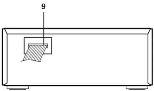
Simple line drawing of a rectangular container with a hatched internal object and a numbered label '9' pointing to the top (no text or symbols on the diagram itself)Rear Panel of Cassette Tape Deck
- System Control Connector
natural_image
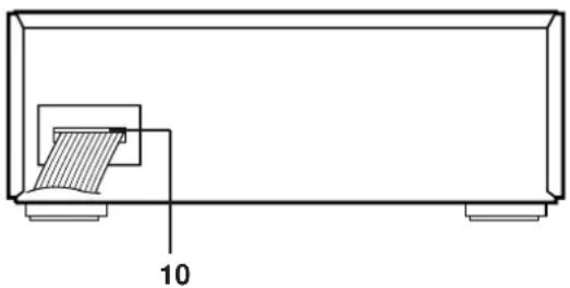
Technical line drawing of a mechanical component with a hatched section and labeled dimension '10' (no text or symbols beyond the label)Rear Panel of CD Player
- System Control Connector
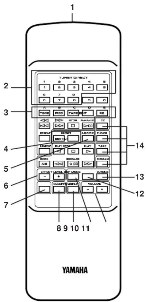
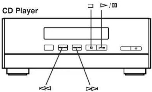
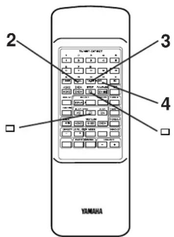
Names of control buttons
■ Receiver Control Buttons
- Remote Control Transmitter Window
- Preset Station Number Buttons
- A, B, C, D, E Selector Buttons
- PRESET DOWN/UP Buttons
- A/B/C/D/E Button
- EFFECT LEVEL Down (-)/Up (+) Buttons
- POWER Switch
- SLEEP Button
- DISPLAY Button
- DSP On/Off Button
- VOLUME Down (-)/Up (+) Buttons
- DSP MODE Selector Button
- SP/PHONES Mode Selector Button
- Input Selector Buttons
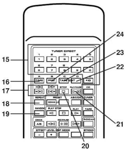
■ CD Player Control Buttons
- Track Number Input Buttons
- TIME Button
- SKIP Buttons: 🐘/▶▶
(SEARCH Buttons: ◀/▶)
- REPEAT Button
- RANDOM Button
- STOP Button:
- PLAY/PAUSE ▷Button:
- EDIT Button
- TAPE Button
- PROGRAM Button
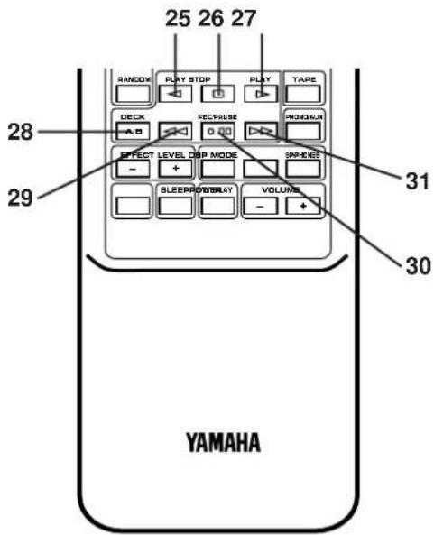
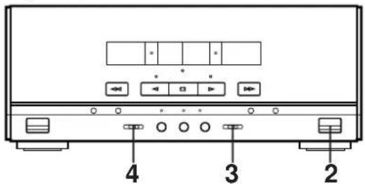
■ Tape Deck Control Buttons
- Play Button: △
- Stop Button: □
- Play Button: ▷
- DECK A/B Select Button
- Fast Wind Button:
- REC/PAUSE Button: ○ □□
- Fast Wind Button: ▷
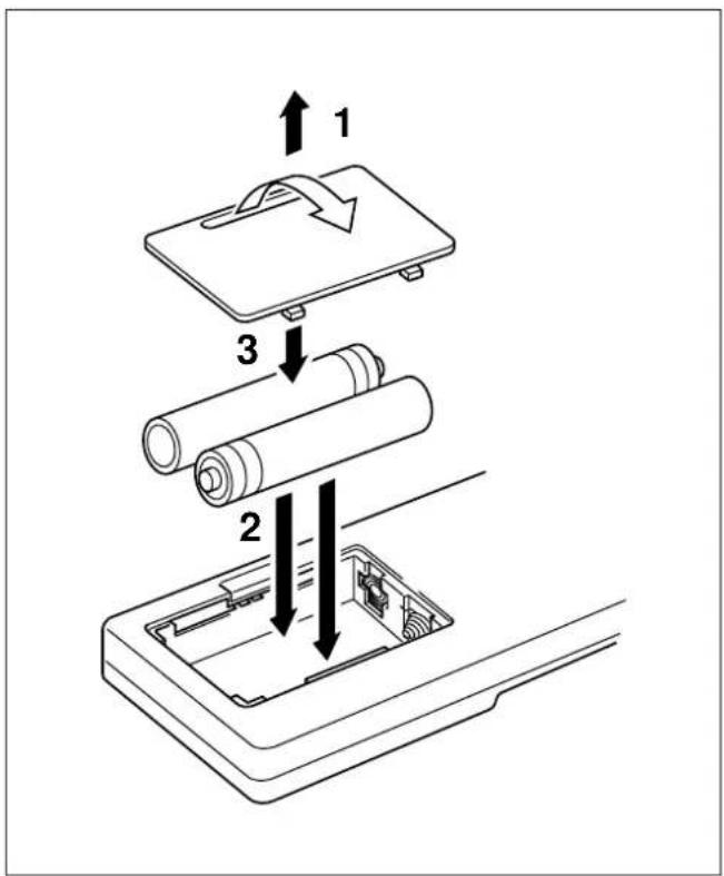
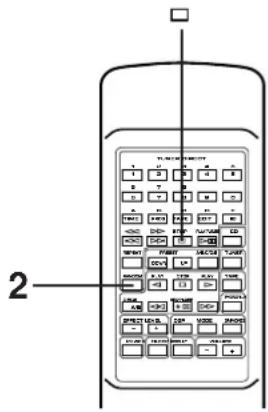
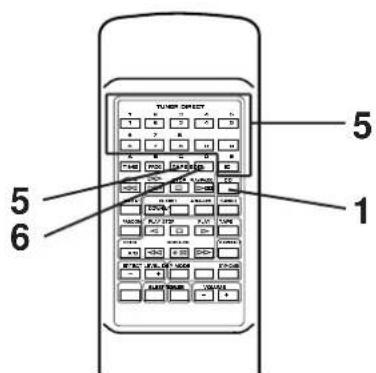
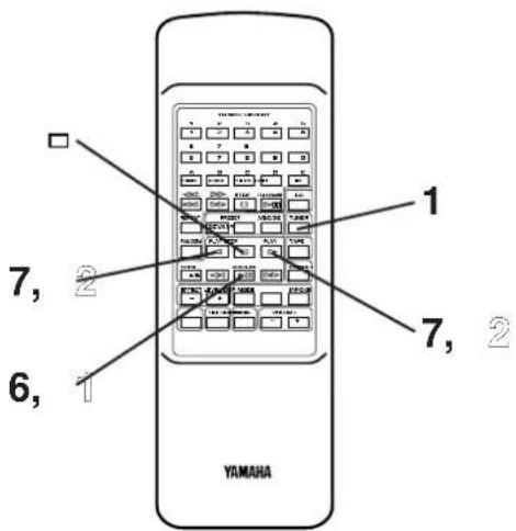
Loading the batteries for the remote control transmitter
1 Remove the battery compartment cover.
(Press the left edge of the cover to right with a finger, and then pull it upward.)
2 Insert 2 "AA" size batteries (UM/SUM-3, R6, HP-7 or equivalent) into the battery compartment.
* Installing the batteries improperly may cause failure.
3 Replace the battery compartment cover.
Precautions for battery use
- Insert the batteries according to the direction indicated in the battery compartment.
- Replace all batteries with new ones at the same time.
- Remove the batteries if they are weak or if the unit is not in use for long periods.
- Don't mix normal batteries with rechargeable batteries.
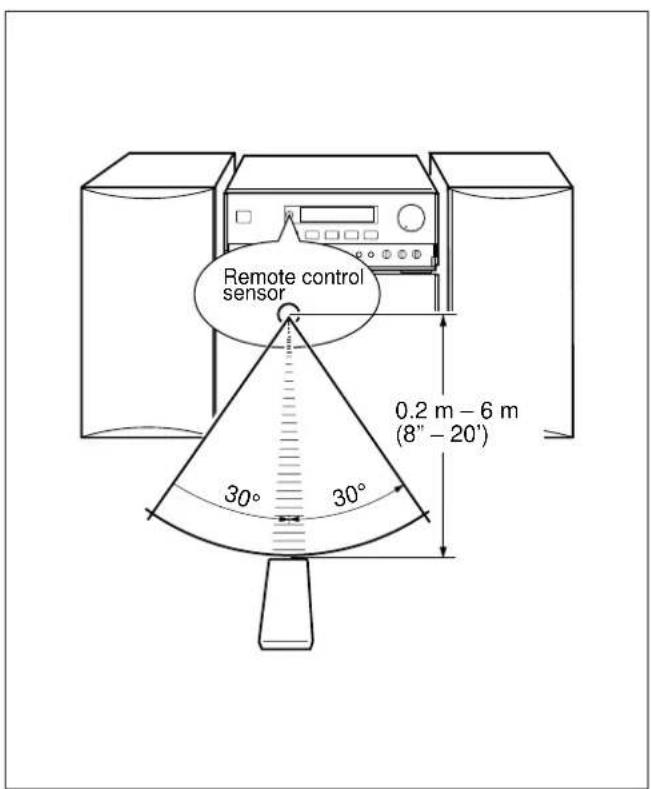
Proper use of the remote control transmitter
Aim (within the range of 60^ with no obstacles) the remote control transmitter at the remote control sensor and operate as shown.
Notes concerning use
- Replace the batteries if control distance decreases or operation becomes unstable.
- Periodically clean the transmitter window on the remote control transmitter and the sensor on the main unit with a soft cloth.
- Exposing the sensor on the main unit to strong light (especially an inverter type of fluorescent lamp etc.) may interfere with operation. In this case, reposition the main unit to avoid direct lighting.
- Keep the remote control transmitter away from moisture, excessive heat, shock and vibrations.
- The remote control transmitter's usable range is within 0.2m (8") and 6m (20') away from the sensor.
PREPARATION FOR USE
Placing examples
flowchart
graph TD
    A["Device 1"] --> B["Computer"]
    B --> C["Switch"]
    C --> D["Laptop"]
    D --> E["Switch"]
    E --> F["Switch"]
    F --> G["Laptop"]
    style A fill:#f9f,stroke:#333
    style B fill:#ccf,stroke:#333
    style C fill:#cfc,stroke:#333
    style D fill:#fcc,stroke:#333
    style E fill:#cff,stroke:#333
    style F fill:#ffc,stroke:#333
    style G fill:#fcc,stroke:#333
* For U.K. and Europe models, "AM" is replaced by "MW LW".
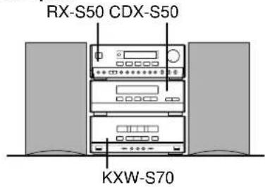
Placing the system
This system can be placed any way you like, however, be sure not to place another unit or any object on top of the receiver to prevent the ventilation holes on the top panel of the receiver from being obstructed. If doing so, it may damage the receiver.
Notes
- If the system is put in a rack, allow a space of at least 5 cm (1-15/16") above and behind the unit.
- Disconnect the AC supply lead from the AC outlet before connecting or disconnecting any component.
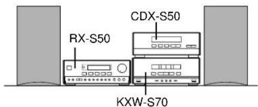
Antenna connection
(1) Supplied FM antenna
Connect the FM antenna wire to the corresponding terminal and direct the FM antenna wire to the direction where the strongest signal can be received.
(2) Supplied AM (MW/LW) loop antenna
Connect the AM (MW/LW) loop antenna wire to the corresponding terminals. Position the AM (MW/LW) loop antenna for optimum reception. Place the AM (MW/LW) loop antenna on a shelf etc., or install it on the rack or wall with screws (not supplied).
Notes
- When static is still heard even after adjusting the position of the AM (MW/LW) loop antenna, try reversing the connection (top to bottom).
- Do not place the AM (MW/LW) loop antenna on the unit. It will result in noise generation, since the unit is equipped with digital electronics. Place the AM (MW/LW) loop antenna away from the unit.
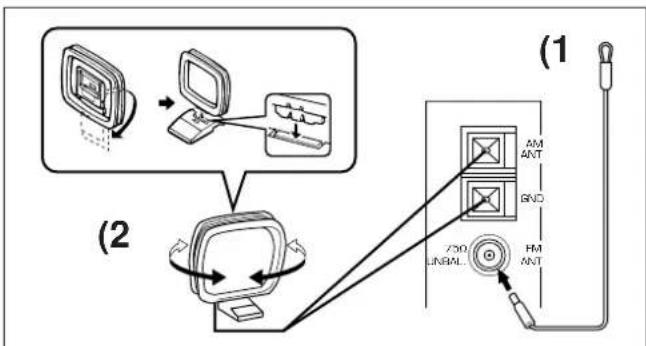
(3) External FM antenna
Use an external FM antenna instead of an indoor FM antenna if you need better reception. Consult your dealer.
(4) External AM (MW/LW) antenna
Use an external AM (MW/LW) antenna if you need better reception. Consult your dealer.
Note
When using an external AM (MW/LW) antenna, be sure to keep the wire of the AM (MW/LW) loop antenna connected.
PREPARATION FOR USE

(Black wire with white line → plus (+) terminal, black wire → minus (−) terminal)
Speaker connection
Connect each speaker wire to the SPEAKERS terminals.
Cautions
- Do not let the bare speaker wires touch each other as this could damage the receiver and/or speakers.
- When connecting the speakers to the unit, be sure to connect the speaker wires properly. Do not mistake the right channel for the left channel and the plus (+) terminal for the minus (−) terminal.
- Do not connect these SPEAKERS terminals to speakers other than the provided speaker system NX-S50.
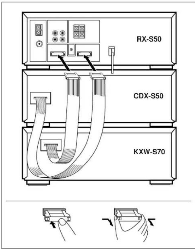
System connection
- Connect the red connector on the rear of CDX-S50 to the red socket on the rear of RX-S50.
- Connect the black connector on the rear of KXW-S70 to the black socket.
How to disconnect the system connector
Grasp both sides of the connector to disconnect the connector.
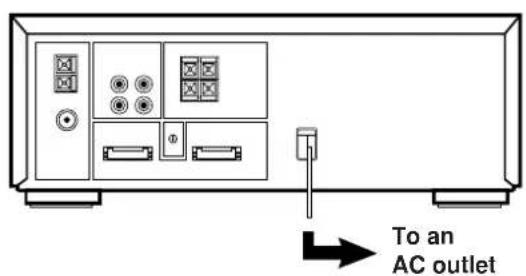
Connecting the AC supply lead
• After connecting the speakers and system connectors, plug the AC supply lead into a convenient AC outlet.
- Unplug the AC supply lead from the AC outlet if the unit is not to be used for a long period of time.
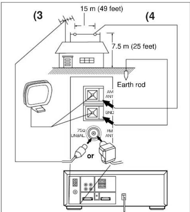
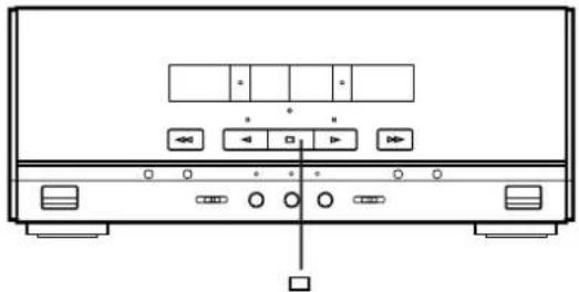
OPEN/CLOSE THE CONTROL DOOR
natural_image
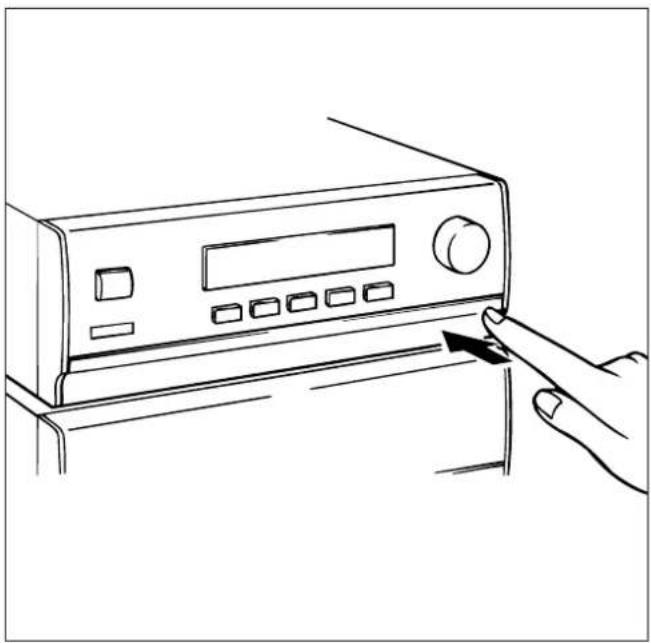
Line drawing of a hand pressing a button on a device panel (no text or symbols)When it is not necessary to operate controls inside the control door, close the door.
To open or close the door, press the right edge until it clicks.
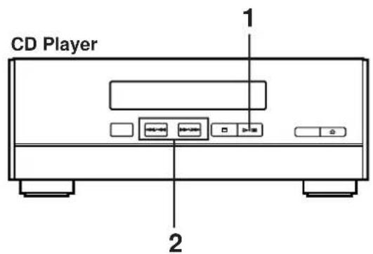
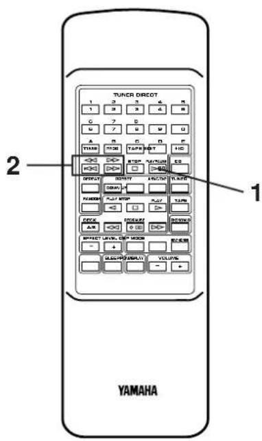
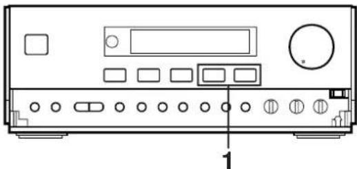
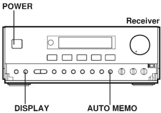
TURNING THE POWER ON/OFF TO THIS SYSTEM
natural_image
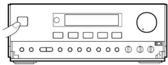
Front view of a portable electronic device with control panel and buttons (no visible text or labels)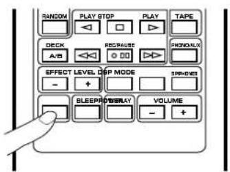
If the AC supply lead is connected to the AC outlet, this system can be turned ON and OFF (STANDBY mode) by pressing the POWER switch on the front panel of the receiver or the POWER button on the remote control transmitter.
STANDBY mode
While the power is on, pressing the POWER switch (or the POWER switch on the remote control transmitter) switches the system to the STANDBY mode. (In this mode, the display shows only the time.) In this mode, main voltage is still present inside the system. If you want to switch off the system completely, disconnect the AC power plug from the AC outlet.
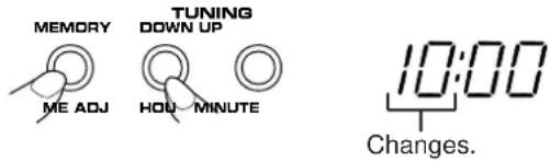
SETTING THE CLOCK
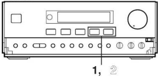
1

2
3
1 While the power is on, press the DISPLAY button to display the time. If the power is off, you can proceed to the next step.
2 While pressing the TIME ADJUST button, press the HOUR button and set the hour.
* Press the HOUR button once to advance the time by 1 hour. Press and hold to advance continuously.
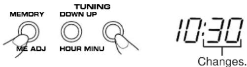
3 While pressing the TIME ADJUST button, press the MINUTE button and set the desired time.
* Press the MINUTE button once to advance the time by 1 minute. Press and hold to advance continuously.
* The hour setting will not advance even if the minute advance from "59" to "00".
To display the time by "second"
While pressing the SEC button, the current time is displayed by minute and second.
To reset the second to "00"
While pressing the SEC button, press the TIME ADJUST button.
* If the current second is lower than 30, it is reset to 00.
* If the current second is higher than 30, the minute is advanced by 1 minute and the second is reset to 00. (If the current minute is "59", in this case, the hour is also advanced by 1 hour.)
In the event of a power failure or when the AC supply lead is disconnected.
The time display will go out, however, the clock will function for about 30 minutes without power supply. So you do not have to reset the time if the AC power supply is resumed within about 30 minutes.
When the AC power supply is resumed after more than 30 minutes pass without power supply, the time display will flash on and off to indicate that the time must be reset.
Note
If this system is left for several minutes without setting the time after the AC power lead of this system is connected to the AC outlet, there may be a case that the display is turned into a demonstration mode. (This mode is virtually unnecessary for using this system.)
In this case, first turn the power on by pressing the POWER switch to cancel the mode, and then set the time.
SOUND CONTROL
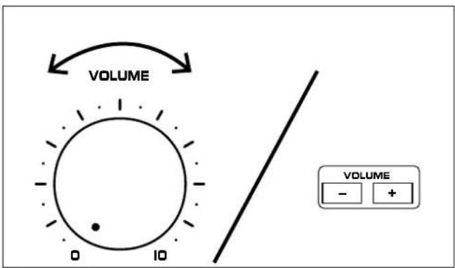

Volume
Front panel operation
Rotate the VOLUME control towards 10 to increase the volume, and towards 0 to decrease the volume.
Remote control operation
Press the VOLUME + button to increase the volume and the VOLUME - button to decrease the volume.
Balance
Adjust the balance of the output volume to the left and right speakers to compensate for sound imbalance caused from the speaker settings or the listening room condition.
Turn this clockwise to emphasize the right and counterclockwise for the left.
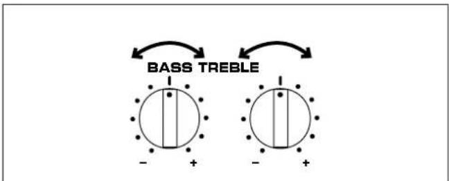
Tone
BASS : Turn this clockwise to increase (or counterclockwise to decrease) the low frequency response.
TREBLE : Turn this clockwise to increase (or counterclockwise to decrease) the high frequency response.
DIGITAL SOUND FIELD PROCESSOR (DSP) CONTROL
flowchart
graph TD
    A["HALL"] --> B["DISCO"]
    B --> C["CHURCH"]
    C --> D["JAZZ CLUB"]
    D --> E["MODE"]
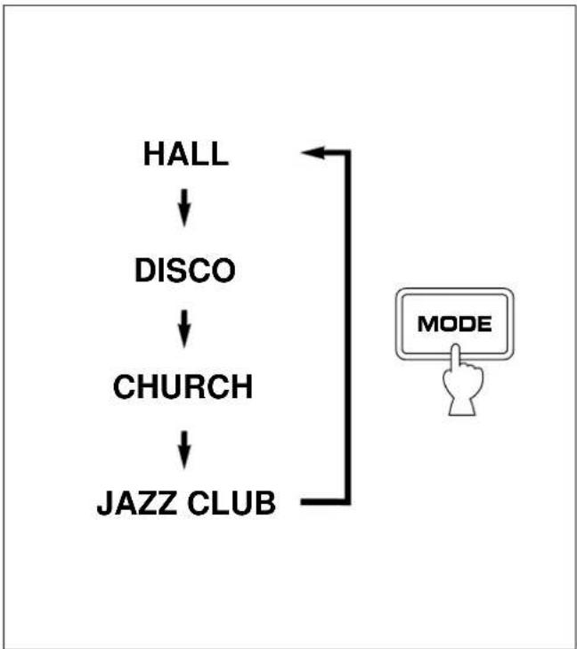
The Digital Sound Field Processor (DSP) built into this unit presents you with the ambience of an actual concert hall, jazz club, etc. by adding effects as sonic reflections or reberverations that create the sound environment of a hall etc.
This unit provides the following 4 DSP modes that simulates actual sound environments.
| Mode | Feature |
| HALL | This mode is suitable for reproducing live recordings of pop or rock music including vocals.You can obtain sound expansion and reverberations of a hall by this mode. |
| DISCO | You can enjoy an atmosphere of disco with lively bass and powerful sound field. |
| CHURCH | This mode creates a rich sound field of church with long reverberations.It is suitable for vocals etc. |
| JAZZ CLUB | This mode creates a sound field with much presence adding spatial effect as if music instruments are coming in front. |
DIGITAL SOUND FIELD PROCESSOR (DSP) CONTROL
Listening to the music with the DSP
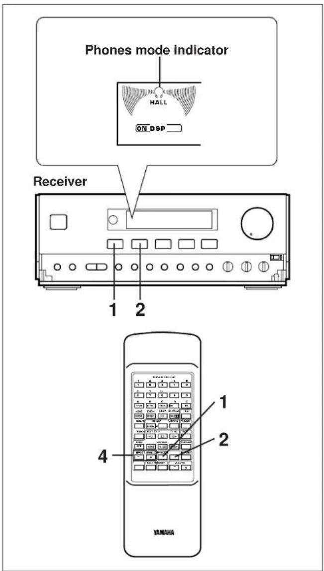
1 Press the DSP ON/OFF switch so that "ON DSP" illuminates on the display.
2 Select a desired DSP mode by pressing the DSP MODE selector button once or more until the name of the mode appears on the display.
3 Playback a source. (For source playback, refer to other sections described later.)
4 Adjust the level of effects by pressing the EFFECT LEVEL down (−) or up (+) button.
* Effect level can be checked with the effect level indicator on the display.
If you will not use the DSP
Press the DSP ON/OFF switch so that "DSP OFF" illuminates on the display.
When listening with headphones
Press the SP/PHONES mode button so that the phones mode indicator is illuminated on the display.
You can obtain a DSP effect suitable for the headphone listening.
If not using headphones, the SP/PHONES mode button should be set so that the phones mode indicator is not illuminated on the display.
Note
DSP effect is also recorded along with a source. If you wish to record a source without DSP effect, turn the DSP off when recording.
Care of compact discs
Compact discs are fairly resistant to damage, however mistracking can occur due to an accumulation of dirt on the disc surface.
Follow the guidelines below for maximum enjoyment from your CD collection and player.
- Do not write on either side of the disc, particularly the non-label side. Signals are read from the non-label side. Do not mark this surface.
- Keep your discs away from direct sunlight, heat and excessive moisture.
- Always hold the CDs by the edges. Fingerprints, dirt or water on the CDs can cause noise or mistracking. If a CD is dirty or does not play properly, clean it with a soft, dry cloth, wiping straight out from the center, along the radius.
natural_image
Line drawing of a CD or DVD disc being inserted into a base case, with no text or symbols present.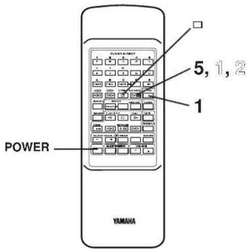
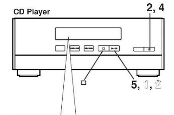
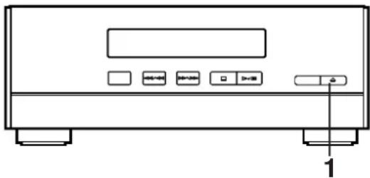
CD playback
1 Select the CD player so that "CD" appears on the display by pressing the INPUT selector of button.
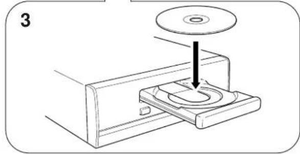
2 Press the OPEN/CLOSE button to open the disc table.
3 Place a disc on the table, label side up.
* 8 cm (3") disc can be played without an adaptor.
4 Press the OPEN/CLOSE button to close the disc table.
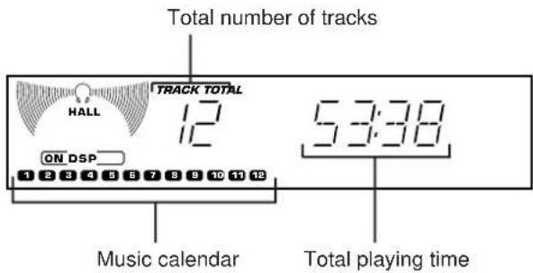
* The total number of tracks and the total playing time of the disc will be displayed for several seconds.
* The music calendar will be displayed only for the number of tracks on the disc.
* If the compact disc contains more than 21 tracks, the "OVER" indicator will light up on the music calendar.
5 Press the play/pause button to start playback from track 1.
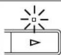
* The “” Indicator will appear and playback will begin. As the playback of each track on the music calendar is finished, that track number will go out.
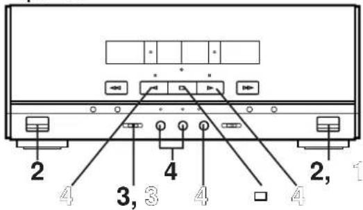
To interrupt playback
1 Press the play/pause button.
* The " indicator will flash.
② Press the play/pause button to resume playback from the same point.
To stop playback
Press the stop button.
To switch the unit off after use
Turn the unit off by pressing the POWER switch. (The indicators will go off except for the current time display.)
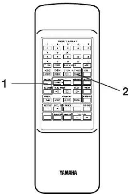
Direct operation
Even when an input source other than CD player is selected, pressing the play/pause button, a track number input button or the RANDOM play button, or pressing the front edge of the disc table gently will start playback directly. In this case, if the tape deck is playing back a tape, it will be stopped automatically.
* These ways of playback can also be used to close the disc table. If the table is closed in these ways, playback will begin automatically, however, the display will not show the total number of tracks and the total playing time of the disc.
Precautions
- If TV or radio interference occurs during CD player operation, move the unit away from the TV or radio.
- Subjecting the unit to shock or vibration can cause mistracking.
- Playing some compact discs at high volume can cause mistracking. In this case, listen at lower volume.
- Do not push the disc table while it is moving.
- If the power fails while the table is open, wait until the power supply returns or gently push the table manually to close it.
- The temperature range for playing compact discs is recommended to be 5°C (41°F) – 35°C (95°F).
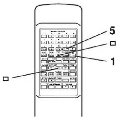
flowchart
graph LR
    A["YAMAHA"] --> B["TUNER DIRECT"]
    B --> C["1 2 3 4 5"]
    B --> D["6 7 8 9 0"]
    B --> E["E HD"]
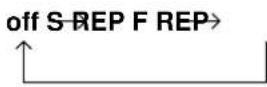
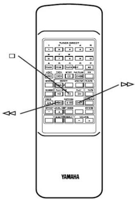
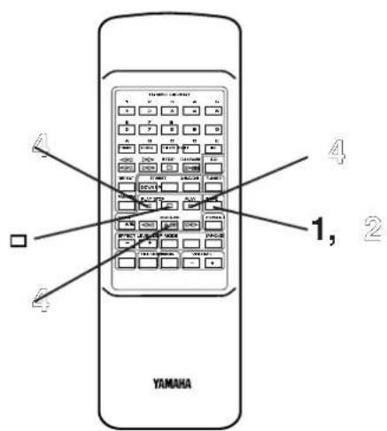
Direct-selection play
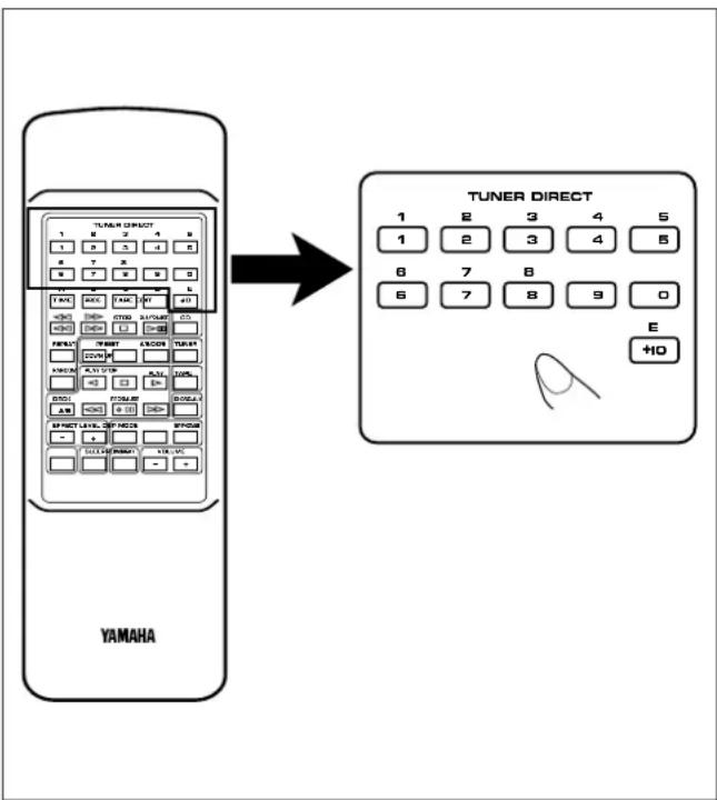
By using the track number input buttons on the remote control transmitter, any track you wish to listen to can be played directly.
Use the track number input buttons to select the desired track number. Play will begin automatically.
A. For example, to choose selection 5
Press the "5" button.
B. For example, to choose selection 12
(1)Press the "+10" button.
(2)Within 3 seconds, press "2" button.
C. For example, to choose selection 20
(1)Press the "+10" button.
(2)Within 3 seconds, press the "+10" button again.
(3)Within 3 seconds, press the "0" button.
Note
A track number higher than the number of tracks on the disc cannot be selected. Also, if a higher track number is selected while the disc table is open, play will begin from the last track on the disc when the disc table is closed.
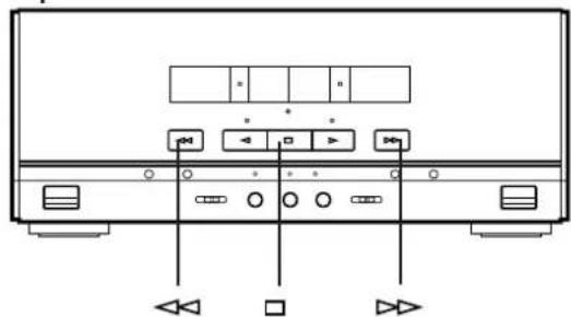
"Skip search" and "Manual search" are performed using the same buttons.
Skip search
The beginning of any track can be found automatically.
1 Load a disc and begin playback.
2 Press the button to advance or button to reverse through the disc. Press once for each track to be advanced or reversed.
- Press once to advance to the track following the one now playing back.
- Press once to return to the start of the track now playing back.
- Press twice to return to the track before the track now playing back.
Notes
- This function can also be performed while the unit is stopped. Press the play/pause button when your desired track number appears in the track number display. Playback will begin from the beginning of the track.
- This function will be performed forward or backward from any point on the disc. However, it will not move forward during playback of the final track.
Manual search
1 Begin playback.
2 Press and hold the button to advance play rapidly, and the button to reverse play rapidly.
* The sound can be heard (although slightly garbled) during manual search in either direction. This is convenient for reviewing the contents quickly.
Note
Manual search can also be performed while playback is paused, though no sound will be heard.
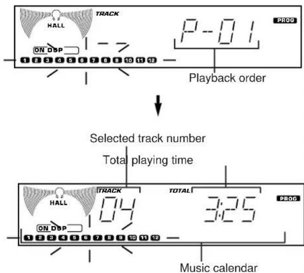
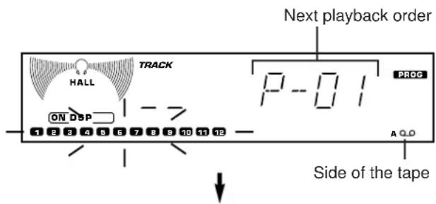
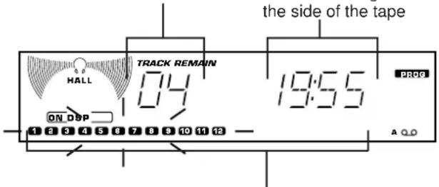
Display information during programming
Program play
You can program up to 20 tracks in any desired order.
1 Load a disc and close the disc table.
2 When in the stop mode, press the PROGRAM button to prepare for programming.
* "PROG" and "P-01" illuminate on the display, and all track numbers on the disc begin flashing.
3 Use the track number input buttons to select the desired track number.
* The selected track number and the total play time of the programmed tracks will illuminate on the display, and soon it is replaced by the display of the next playback order. Programmed track numbers will stop flashing and illuminate on the music calendar.
* Pressing the TIME button displays the total play time of the programmed tracks for about 1 second, and then it is replaced by the display of the next playback order.
* For example, to choose selection 12
(1)Press the "+10" button.
(2)Press the "2" button.
4 Repeat step 3 for any other track. Up to 20 tracks can be programmed.
5 Press the play/pause button to start playback of programmed tracks.
Notes
- It is also possible to program a sequence of tracks while looking at the list of tracks on the surface of the disc before closing the disc table.
- During playback or pause, programming is not possible.
- If the total time of the programmed tracks reaches 100 minutes or more, only the last two-digits will be displayed for the three-digit number.
- The total time of the programmed tracks will not be displayed, if a track number higher than 19 is programmed.
- Skip search can be performed during playing back, but only within the range of the programmed tracks.
- Manual search can be performed during playing back to search through all tracks, including unprogrammed tracks.
To stop program play
- Press the stop button. The first track number programmed will be displayed.
- To resume playback, press the play/pause button. Playback will begin from the beginning of the program.
To cancel a programmed sequence
There are several methods as described below.
- Press the stop button while the unit is stopped.
- Open the disc table
- Switch off the power.
To check program data
- If during playing back, press the stop button.
- Press the PROG button.
- Each time the SKIP button is pressed, the track numbers and sequential order of the programmed tracks can be checked one after another. The display of the track number can be returned (sequentially in reverse order) by pressing the SKIP button.
To correct program data
- Follow the procedure described in "To check program data".
- Display the track number to be corrected by pressing the SKIP button.
- Press a track number input button to select a track to replace the one displayed. The previously programmed track will be cleared from the memory and the new one will be programmed.
- After the correction has been completed, press the PROG button or play/pause ▷ button once again.
CD Player
Repeat play
An entire disc, a single track or a programmed sequence can be continuously repeated.
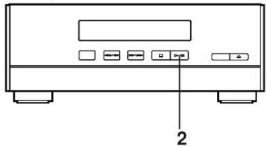
1 While watching the display, press the REPEAT button once or more to select a desired repeat play mode (S REP or F REP).
2 Press the play/pause button.
Repeat play modes
SINGLE REPEAT (S REP)
A single track is played back repeatedly.
* This is also available in the program play mode and the random play mode. (If the repeat play mode is switched off, the program play mode or the random play mode will be resumed.)
FULL REPEAT (F REP)
An entire disc is played back repeatedly.
* In the random play mode, the disc is repeatedly played back, but the order of tracks is different every time.
To cancel the repeat play
Press the REPEAT button once or more so that the (S, F) REP indicator goes out.
flowchart
graph TD
    A["Yamaha"] --> B["① TRACK HALL 02 0:08 ▷"]
    B --> C["② TRACK REMAIN HALL 02 3:58 ▷"]
    C --> D["③ TRACK TOTAL HALL 02 4:523 ▷"]
    D --> E["④ TRACK TOTAL REMAIN HALL 02 4:00 ▷"]
Random play
The tracks on the disc can be played back in a random order.
1 Load a disc and close the disc table.
2 Press the RANDOM button to begin random play.
* The "RANDOM" indicator will light up.
To cancel the random play
Press the stop button. The "RANDOM" indicator goes out.
Note
This feature will not function during programming, or during program play.
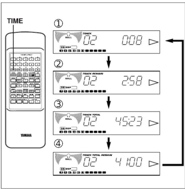
Switching the time display
Each time the TIME button is pressed, the display will change as described below.
[Example]
When the second track is being played back (Refer to the illustration on the left.)
①The elapsed play time for the track now playing back will be displayed.
* 8 seconds have passed since the beginning of the second track.
②The remaining play time for the current track will be displayed.
* 2 minutes and 58 seconds remain till the end of the second track.
③The total play time of the disc will be displayed.
(If the unit is in the program play mode, the total play time of the programmed tracks will be displayed.)
④The total remaining play time from the point being played at that time will be displayed.
* 41 minutes remain till the end of the disc.
Notes
- During random play, the total remaining play time on the disc will not be displayed.
- The total remaining play time will not be displayed for track number 20 or higher.
"AM" is for Australia and General models. "MW/LW" is for U.K. and Europe models.
Normally, if station signals are strong and there is no interference, quick automatic-search tuning (Automatic tuning) is possible. However, if signals of the station you want to select are weak, you must tune to it manually (Manual tuning).
Automatic tuning
1 Select the tuner so that "TUNER" appears on the display by pressing the INPUT selector of button.
2 Select the reception band [FM or AM (MW or LW)] by pressing the BAND button while watching the display.
3 Press the AUTO/MAN'L button so that "AUTO TUNING" appears on the display.
(In this mode, stations are received in stereo or monaural automatically.)
4 Press the TUNING UP button to tune to a higher frequency, or press the TUNING DOWN button to tune to a lower frequency.
5 If the station where tuning search stopped is not the desired one, follow step 4 again.
* If the tuning search does not stop at the desired station, change to the Manual tuning method as described below.
* STEREO indicator will illuminate when an FM stereo broadcast with sufficient signal strength is received.
Manual tuning
1 Follow steps 1 and 2 of the Automatic tuning method.
2 Press the AUTO/MAN'L button so that "AUTO TUNING" disappears from the display.
(In this mode, stations are received in monaural.)
3 Press and hold the TUNING UP button to tune to a higher frequency, or press and hold the TUNING DOWN button to tune to a lower frequency.
Release it just before reaching the desired frequency, and then press it repeatedly until the desired frequency appears.
Note
If you tune to an FM station manually, it is received in monaural automatically to increase the signal quality.
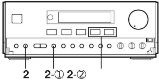
Preset tuning
This unit can store station frequencies selected by tuning operation. With this function, you can select any desired station by only calling the corresponding preset station number. Up to 40 stations (8 stations x 5 areas) can be stored.
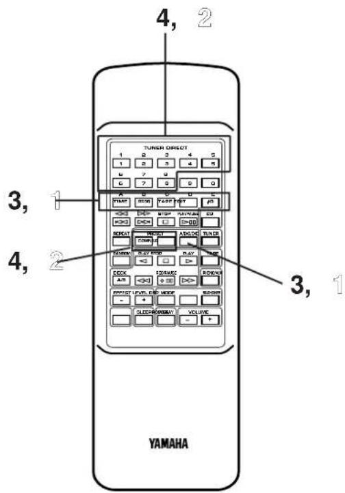
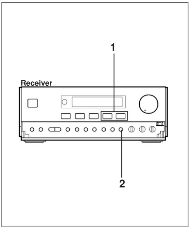
To store stations
(Example: To store a station to A1)
1 Tune to a desired station.
(Refer to the previous page for tuning procedure.)
2 Press the MEMORY button.
* The MEMORY indicator will flash for about 5 seconds.
3 Select a desired area (A - E) by pressing the A/B/C/D/E button while watching the display, before the MEMORY indicator goes out.
(In this case, select area A)
4 Select a preset station number by pressing the TUNER PRESET DOWN or UP button repeatedly before the MEMORY indicator goes out.
(In this case, select "1".)
5 Within about 5 seconds, press the MEMORY button again.
* In the same way, program other stations to A2, A3 ... A8.
* You can program more stations to the preset station numbers on other areas in the same way by selecting other areas in step 2.
To recall a preset station
1 Select the area of preset station numbers by pressing the A/B/C/D/E button.
2 Select the desired preset station number by pressing the TUNER PRESET DOWN or UP button repeatedly.
Notes
- A new setting can be programmed in place of the former one.
- For presets the setting of the AUTO/MAN'L button is stored along with the station frequency.
For easier operation
By using the preset station number buttons and the A,B,C,D,E selector buttons on the remote control transmitter, a preset station number and an area can be selected directly.
Automatic preset tuning
You can also make use of an automatic preset tuning function. By this function, this unit performs automatic tuning and stores stations with strong signals sequentially. Up to 40 stations are stored automatically in the same way as in the manual preset tuning method on the previous page.
1 Select the tuner so that "TUNER" appears on the display by pressing the INPUT selector or button.
2 Press and hold the AUTO MEMORY button for about 2 seconds.
* The MEMORY and AUTO TUNING indicators will flash.
This unit performs automatic tuning and received stations are programmed to A1, A2 ... A8 sequentially.
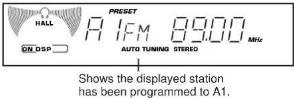
After the automatic preset tuning is completed
The display shows the frequencies of the first preset station (stored to A1).
Check the contents and the number of preset stations by following the procedure of the section "To recall a preset station" on the previous page.
To recall a preset station
Simply follow the procedure of the section "To recall a preset station" on the previous page.
Notes
- The automatic preset tuning search will be performed through all frequencies until 40 stations are stored. If the number of received stations is less than 40, the search will stop after searching through all frequencies.
- With this function, only stations with sufficient signal strength are stored automatically. If the station you want to program is weak in signal strength, tune to it in monaural manually and program it by following the procedure of the section "To store stations" on the previous page.
- You can replace a preset station by another FM or AM (MW or LW) station manually by simply following the procedure of the section "To store stations" on the previous page.
Fundamental rules of internal automatic preset tuning operation
Basically, FM stations are programmed onto area A, B and C, and AM stations are programmed onto area D and E (MW stations are onto D and LW stations are onto E) in that order automatically.
* If, for example, the number of received FM stations is not enough to fill up three areas (A, B and C), AM (MW or LW) stations are programmed closely from the preceding empty areas. In such a case, AM (MW) stations are programmed from area B or C (and LW stations are from area C or D.)
* Moreover, one area is programmed with stations of the same band only. If, for example, the last FM station is programmed to B4, B5–B8 will be programmed with no station, and AM (MW) stations are programmed from area C.
Memory back-up
The memory back-up circuit prevents the programmed data from being lost even if the AC supply lead is disconnected from the AC outlet or the power is cut due to temporary power failure. If, however, the power is cut for more than one week, the memory may be erased. If so, it can be re-programmed by simply following the Preset tuning steps.
General information
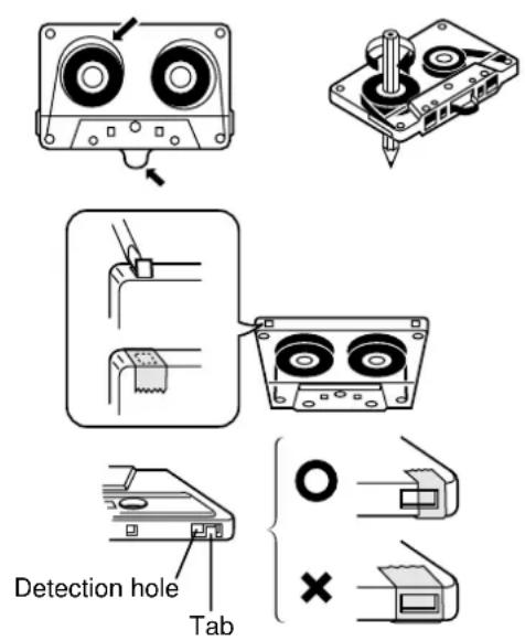
- Do not use C-120 tapes, tapes with internal reels or poor-quality tapes, since they can cause malfunctions.
- Before loading a tape into the cassette compartment, tighten the slack tape with a pen or pencil.
- Tapes have removable tabs which prevent accidental recording or erasing from taking place. Removing the tab on the top left protects the side facing you from erasure. Cover the tab holes with adhesive tape to erase or record again.
- This deck is a Double Cassette Deck with Automatic Reverse Function.
DECK A: Playback only.
DECK B: Playback or recording.
- This deck features an auto tape selector. Just load the tape, and the tape formula being used will be sensed automatically.
- This unit can play back metal tapes as well as normal or chrome tapes, and recording can also be done on metal tapes.
- When covering erasure prevention tab holes, do not cover the chrome and metal detection holes. Otherwise, the deck will treat tape as normal tape.
- Do not press the EJECT button during playback or recording.
Tape A or tape B playback
1 Select the tape deck so that "TAPE" appears on the display by pressing the INPUT selector or button.
2 Open the DECK A or DECK B cassette compartment by pressing the EJECT button.
3 Load the tape into the DECK A or DECK B cassette compartment, and close the lid panel completely by pressing the upper part of the center of the panel as figured left.
* If you loaded two tapes into both the DECK A and B cassette compartments, select the DECK A or B in which the tape to be played back is loaded by pressing the DECK A or B select button.
4 Set the Dolby NR switch to B or C if the tape has been recorded with Dolby noise reduction, and to OFF if Dolby NR was not used.
* For selection of the Dolby B or C position, refer to the "Dolby B and C Type Noise Reduction" on page 29.
5 Set the reverse mode switch as desired.
The reverse mode switch can be operated before or during playback, and changes tape playback as follows:
 | Side A only | Side A → Side B | Side A → Side B Continuous play (8 times) |
 | Side B only | Side B only | Side B → Side A Continuous play (8 times) |
6 Press the play button to listen to side A, or the play button for side B.
To stop playback
Press the stop button.
Note
When removing the tape, press the stop button, and then open the cassette compartment.
Direct operation
Even if an input source other than tape deck is selected, pressing the play button (or the fast wind button) will start playback (or fast winding) directly.
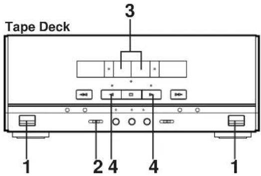
Tape Deck
Winding the tape
1 If during playback, first press the stop button.
2 Next press the fast wind or fast wind button to wind the tape.
3 Press the stop button to stop.
* While winding the tape, the corresponding play direction indicator flashes rapidly.
Note
When the tape is wound to the end, this unit will then function as described below, according to the setting of the reverse mode switch.
→: The tape stops at the end.
: If the winding direction is ▷ when the tape reaches the end, playback automatically starts from the reverse side.
If the winding direction is ,the tape stops at the end.
: When the tape reaches the end, playback automatically starts from the reverse side.
Searching for the beginning of a desired selection
Carry out the following operation during playback to find the beginning of a desired selection on the tape.
To listen to the same selection
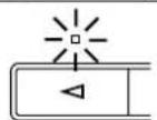
Press the button if the direction of the current playback is ▷.
Press the button if the direction of the current playback is △.
To listen to the next selection
Press the button if the direction of the current playback is ▷.
Press the button if the direction of the current playback is △.
* While searching, the corresponding play direction indicator flashes slowly.
Notes
• This function may not work for tapes with
* Material with long pauses or quiet passages.
* Low recording levels or excessive noise.
* Pauses of less than 4 seconds between selections.
- If searching is carried out at the first or the last part of a selection, the searching may not function correctly.
TAPE DECK OPERATION
Dolby B and C Type Noise Reduction
With cassette tapes, the most noticeable form of noise is high frequency hiss. To reduce this hiss noise, this unit has been equipped with a newly developed Dolby C noise reduction system in addition to its conventional Dolby B NR. Either type of noise reduction may be selected with the switch provided. Dolby B NR has a noise reduction effect of about 10 dB in the high frequency range. The corresponding figure with Dolby C NR is about 20 dB, but this is over the entire range where the human ear is most sensitive to noise (2 kHz to 8 kHz). Also, Dolby C NR has the same noise reduction effect at both high and low signal levels. In addition, Dolby C NR improves the tape's MOL (Maximum Output Level). Dolby noise reduction is a 2 part process that acts both on recording and playback; be sure that the noise reduction button is set to the same position on record and play. * Noise in the source material cannot be reduced with the Dolby NR system.
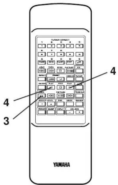
Continuous playback
1 Load the tapes into the DECK A and DECK B cassette compartments.
2 Set the reverse mode switch to .
The reverse mode switch can be operated before or during playback, and changes tape playback as follows:
 | Tape A Side A → B → Tape B Side A → BContinuous play (8 times) |
| Tape A Side B → Tape B Side A → B→ Tape A Side AContinuous play (8 times) |
3 Press the DECK A or B select button to select the tape to be played back first.
4 Press the play button to listen to side A, or the play button for side B.
DO DOLBY B:C NR
Dolby and the double D mark are trademarks of Dolby Laboratories Licensing Corp. Dolby noise reduction system manufactured under license from Dolby Laboratories Licensing Corp.
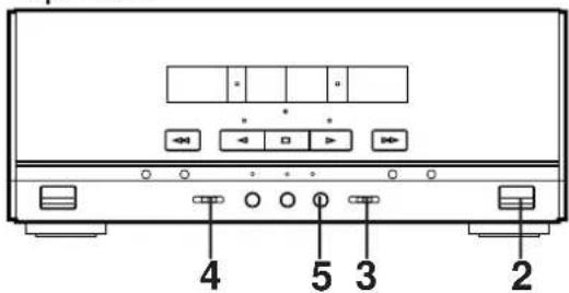
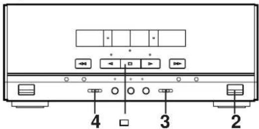
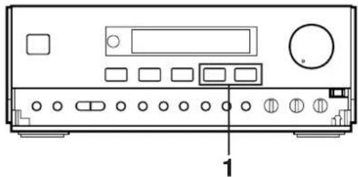
Receiver
natural_image
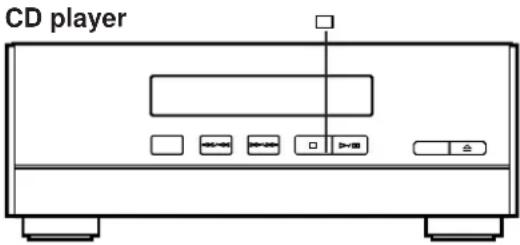
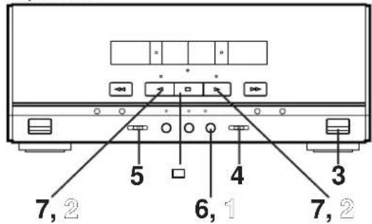
Front view diagram of a portable electronic device with buttons and ports (no text or labels)CD Player
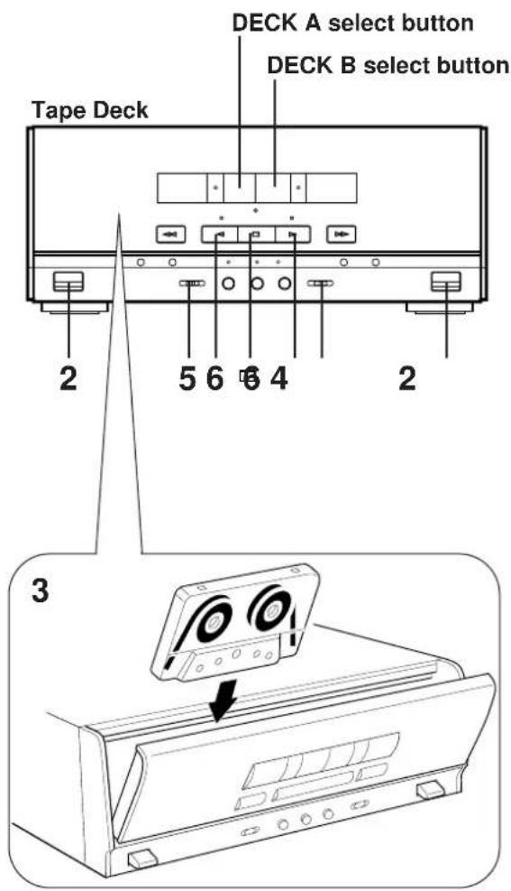
Tape Deck
- When recording important selections, be sure to make a preliminary test to ensure that the desired source material is being properly recorded with good sound quality.
- The automatic recording level control circuit automatically controls the level of the input signal used for recording.
- Adjusting the VOLUME, BALANCE, TREBLE and BASS controls have no effect on the recorded sound. If, however, the DSP is on, the DSP effect is recorded along with the source.
* Music with DSP effect is suitable for listening to inside a car etc. - For the tape deck, the deck which can be used for recording is the DECK B only. When recording, be sure to load a tape into the DECK B cassette compartment.
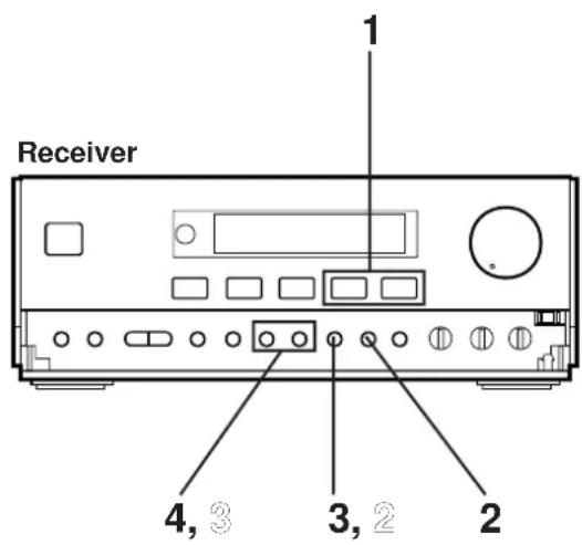
CD synchronized recording
1 Select the CD player so that "CD" appears on the display by pressing the INPUT selector of button, and load the disc to be recorded.
2 Load a tape into the DECK B cassette compartment. * Wind past the beginning part of the tape on which recording can not be performed.
3 When recording with the Dolby NR system, set the Dolby NR switch to B or C; if not, set it to OFF.
* For selection of the Dolby B or C position, refer to the "Dolby B and C Type Noise Reduction" on page 29.
4 Set the reverse mode switch as desired.
When the tape is set so that side A faces you, recording will be done as follows automatically according to the selected reverse mode.
 | Side A only | Side A → Side B | Side A → Side B |
 | Side B only | Side B only | Side B only |
5 Press the REC/PAUSE button.
* The corresponding indicator will light up and the play direction indicators flash.
6 Start CD playback by pressing the play/pause button.
* Before CD playback begins, recording automatically begins on the side of the tape now selected.
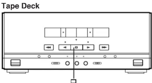
Tape Deck
natural_image
Front view diagram of a computer monitor with control buttons and indicator lights (no text or labels)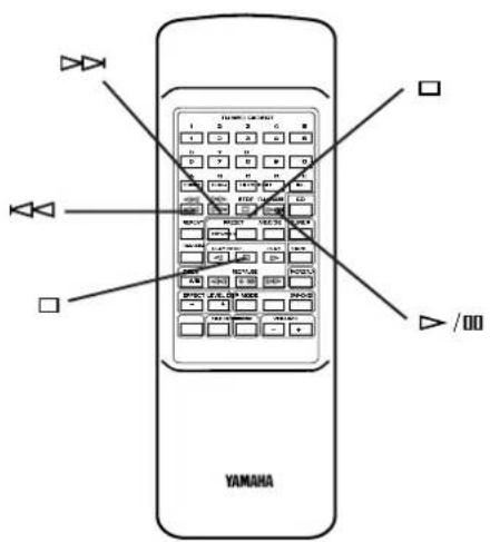
To stop recording temporarily
1 Press the stop button of the CD player.
2 Choose the selection to be recorded next by using the SKIP of button, and then press the play button of the CD player to resume recording (or simply press the track number input button on the remote control transmitter).
To stop recording
Press the stop button of the tape deck. (At this time, CD playback does not stop.)
Recording programmed tracks
Programmed tracks can also be recorded in the same way.
1 Program desired tracks. (Refer to page 19 for the programming procedure.)
2 Follow steps 2–5 on the previous page.
3 Press the play/pause ▶ button of the CD player.
Notes
- During CD Synchronized Recording, when more than 4 seconds elapse between tracks, the tape will stop automatically and resume recording when the beginning of the next track is found.
- The CD Synchronized Recording will function even when the CD player is turned into random play mode.
Receiver
natural_image
Front view of a portable electronic device with buttons and ports (no visible text or labels)CD Player
Tape Deck
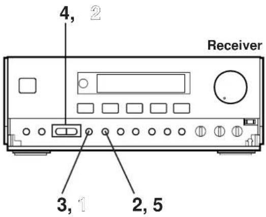
Recording CD on both sides of a tape automatically
1 Select the CD player so that "CD" appears on the display by pressing the INPUT selector of button, and load the disc to be recorded.
2 Load a tape into the cassette compartment.
3 When recording with the Dolby NR system, set the Dolby NR switch to B or C; if not, set it to OFF.
* For selection of the Dolby B or C position, refer to the "Dolby B and C Type Noise Reduction" on page 29.
4 Set the reverse mode switch to or.
5 Press the EDIT button. ("EDIT" appears on the display.) CD playback and recording starts. Recording is carried out on side A and B of the tape continuously.
* If the tape has not rewound to the end, it is rewound to the end rapidly before recording starts. Recording starts from the first part of the tape on which recording can be done.
* "A" (or B) on the display shows the side of the tape on which recording is being carried out.
* When the recording on side A finishes while a track is being played back, the sound is automatically faded out, and then the recording stops.
The recording on side B starts from the beginning of the same track.
Note
The CD player's repeat play mode will be canceled during this recording mode.
Recording programmed tracks
Programmed tracks can also be recorded in the same way.
1 Program desired tracks. (Refer to page 19 for the programming procedure.)
2 Follow steps 2–5 described above.
To cancel this function
Before recording, press the stop button of the CD player or the tape deck.
To stop recording
Press the stop button of the tape deck. (At this time, CD playback automatically stops.)
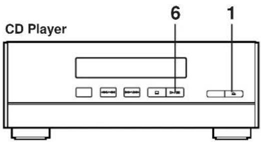
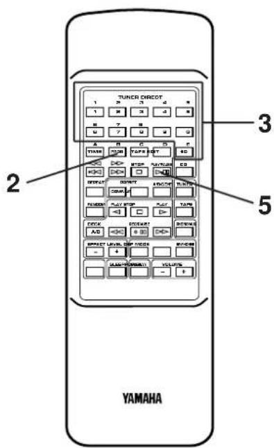
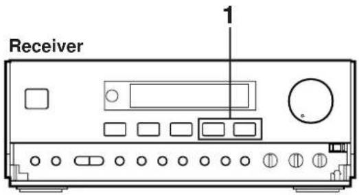
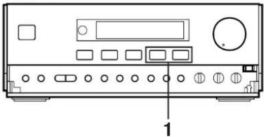
Receiver
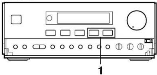
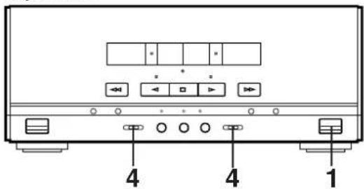
natural_image
Front view diagram of a electronic device with ports and buttons, labeled with number 1 (no text or symbols on the device itself)CD Player
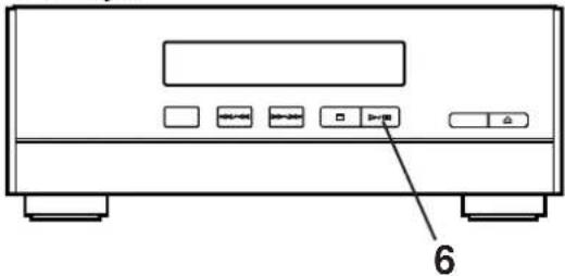
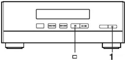
natural_image
Front view of a portable electronic device with buttons and a labeled indicator (no text or symbols beyond basic diagram)Tape Deck
Automatic tape-editing
This convenient feature can be used to program tracks on a disc for recording to tape. By only memorizing the tape's total possible recording time, the unit will automatically program tracks or help you to program tracks so they will fit onto the tape with the least amount of unrecorded space remaining at each end of the tape.
To record a disc with the order of tracks unchanged
1 Select the CD player so that "CD" appears on the display by pressing the INPUT selector of button, and load the disc to be recorded.
2 Load a tape into the cassette compartment.
3 When recording with the Dolby NR system, set the Dolby NR switch to B or C; if not, set it to OFF.
* For selection of the Dolby B or C position, refer to the "Dolby B and C Type Noise Reduction" on page 29.
4 Set the reverse mode switch to ☑.
5 Press the TAPE button to select the length of the tape to be used. Whenever pressed, C-46, C-54, C-60 and C-90 appear on the display in turn, and next it returns to the normal display mode.
$$ \begin{array}{c}\text {off} \rightarrow \text {C - 46} \rightarrow \text {C - 54} \rightarrow \text {C - 60} \rightarrow \text {C - 90}\\uparrow\end{array} $$
When using tapes other than C-46, C-54, C-60 or C-90
When C-46, C-54, C-60 or C-90 is appearing on the display, input the tape length by using the track number input buttons on the remote control transmitter (Examples)
C-62: Press "6" and then "2".
C-30: Press "3" and then "0", or press "+10" three times and then "0".
6 Press the EDIT button. ("EDIT" appears on the display.) The following internal operations are carried out before recording is automatically started.
1) Tracks on the disc are automatically divided between side A and side B. You can check the process by watching the display.
2) The end part of the tape on which recording cannot be done is wound.
3) This unit starts searching for a peak level through all tracks to be recorded. (While searching, "LEVEL" flashes on the display.) When searching is finished, this unit adjusts the recording level properly on the basis of this data.
4) CD playback and recording starts. Recording is carried out on both side A and B of the tape.
Note
The CD player's repeat play mode will be canceled during this recording mode.
To cancel tape-editing function
Before recording, press the stop button of the CD player or the tape deck.
To stop recording
Press the stop button of the tape deck.
(At this time, CD playback automatically stops.)
To make this unit program tracks on a disc automatically so that the least amount of unrecorded space remains on the tape
1 Follow steps 1–5 on the previous page.
2 Press the PROGRAM button.
3 Press the TAPE button.
“AP A> ^a illuminates during programming for side A, and
“AP B> ^a illuminates during programming for side B.
* After "AP B > ^a goes out from the display, you can check the programmed contents for side A and B respectively. To check, cancel or correct program data, refer to page 20.
4 Press the EDIT button. ("EDIT" appears on the display.) The recording is automatically started.
* The unit searches for a peak level on each track to adjust the recording level properly. The search is carried out before recording each track. (While searching, "LEVEL" flashes on the display, and recording is paused.)
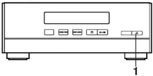
Receiver

natural_image
Front view diagram of a computer or electronic device chassis with labeled ports and buttons (no text or symbols beyond basic labels)CD Player
natural_image
Line drawing of a front-mounted electronic device with control buttons and indicator lights (no text or symbols)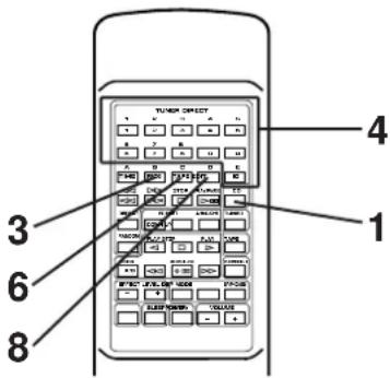
Display information during programming
Selected track number
Programmed track numbers illuminate and unprogrammed ones flash.
To record programmed tracks
1 Select the CD player so that "CD" appears on the display by pressing the INPUT selector of button, and load the disc to be recorded., and load a disc on the disc table.
2 Follow steps 2–5 on page 33.
3 Press the PROGRAM button.
* "PROG" and "P-01" illuminate on the display, and all track numbers on the disc begin flashing.
4 Use the track number input buttons to select the desired track number.
5 Repeat step 4 to set more programs for the side A of the tape. You can select the same track again.
* Pressing the TIME button displays the total remaining time on the side of the tape for about 1 second, and then it is replaced by the display of the next playback order.
* If "ERR" appears on the display, the track number just selected cannot be programmed because there is not enough time remaining on the side A of the tape. However, at this time, if any other track number is flashing continuously on the display, you can program it instead of the unprogrammable one.
6 After you finish the programming for the side A, press the TAPE button.
* "Pu" appears on the display, then you can begin programming for side B.
7 Repeat step 4 to set more programs for the side B of the tape. You can select the same track again.
* If "ERR" appears on the display, the track number just selected cannot be programmed because there is not enough time remaining on the side B of the tape. However, at this time, if any other track number is flashing continuously on the display, you can program it instead of the unprogrammable one.
8 Press the EDIT button. ("EDIT" appears on the display.) The recording is automatically started.
* The unit searches for a peak level on each track to adjust the recording level properly. The search is carried out before recording each track. (While searching, “LEVEL” flashes on the display, and recording is paused.)
Notes on tape-editing
- To check, cancel or correct program data, refer to page 20.
- The maximum number of tracks that can be programmed is 20.
- This function can be used to program up to track number 20. If the disc has more than 20 tracks, track number 20 and thereafter will not be programmed.
OTHER RECORDINGS
Receiver
natural_image
Front view diagram of a portable electronic device with buttons and display (no text or symbols)Tape Deck
Recording from the built-in tuner
1 Select the tuner so that "TUNER" appears on the display by pressing the INPUT selector of button.
2 Tune to the desired station. (Refer to the "TUNING OPERATION" on pages 23 and 24.)
3 Load a tape into the cassette compartment.
4 When recording with the Dolby NR system, set the Dolby NR switch to B or C; if not, set it to OFF.
* For selection of the Dolby B or C position, refer to the "Dolby B and C Type Noise Reduction" on page 29.
5 Set the reverse mode switch to record on only one side, or to (or) for continuous recording on both sides.
6 Press the REC/PAUSE button.
* The corresponding indicator lights up and the play direction indicators flash.
7 Press the play button to record on side A, or the play button to record on side B.
* For continuous recording on both sides, begin on side A. Recording stops automatically at the end of side B.
To stop recording temporarily
Press the REC/PAUSE button.
2 To resume recording, press the play button whose indicator is flashing.
To stop recording
Press the stop button.
Receiver
Tape Deck
Dubbing
- During dubbing, adjusting the VOLUME, BALANCE, TREBLE and BASS controls have no effect on the recorded sound.
If, however, the DSP is on, the DSP effect is recorded along with the source.
* Music with DSP effect is suitable for listening to inside a car etc. - Try to use the same tape formula and length for the recording tape as for the master tape.
1 Select the tape deck so that "TAPE" appears on the display by pressing the INPUT selector of button.
2 Load a prerecorded tape into the DECK A cassette compartment. Insert a blank tape into the DECK B cassette compartment.
3 Set the reverse mode switch to record on only one side, or to (or) for continuous recording on both sides.
4 Press the DUBBING button.
* Press "NORMAL" to dub at normal speed, and "HIGH" to dub at about twice the normal speed.
* Dubbing will begin from side A regardless of the side now selected.
To stop dubbing
Press the stop button.
* Tape A and tape B will stop at the same time.
Note
Only tapes originally encoded with Dolby B or C NR will be dubbed onto tapes with Dolby B or C NR encoding.
The Dolby NR switch will have no effect on the recording of tape B during dubbing.
However, the playback tonal quality of tape A will change according to the Dolby NR switch position.
Erasing recorded tapes
Load the tape to be erased into the DECK B cassette compartment.
② Select the tape deck so that "TAPE" appears on the display by pressing the INPUT selector of button.
③ Set the reverse mode switch to erase only one side and to (OP) to ↗ erase both sides.
4 Press the REC/PAUSE button, then press the play button to erase side A of the tape, or the play button to erase side B.
Receiver
Timer play
By using the built-in timer, you can set the time when the unit turns on and a source begins playing automatically, and the time when the unit turns off automatically.
1 Prepare the source to be played.
For tuner:
Tune in to the station you will listen to.
For tape deck:
Load a tape into the cassette compartment.
(If tapes are loaded in both the compartments, tape A takes priority of tape B, and is played back by the timer play.)
For CD player:
Load a disc on the disc table.
2 Press the DISPLAY button.
Whenever the DISPLAY button is pressed, the display mode changes as follows.
At each mode, make a setting for the timer play, referring to the setting procedure described below.
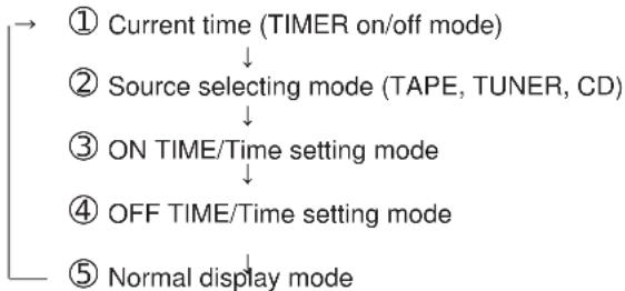
flowchart
graph TD
    A["① Current time (TIMER on/off mode)"] --> B["② Source selecting mode (TAPE, TUNER, CD)"]
    B --> C["③ ON TIME/Time setting mode"]
    C --> D["④ OFF TIME/Time setting mode"]
    D --> E["⑤ Normal display mode"]
* The display mode will be changed to the next mode after about 8 seconds elapse automatically. If the mode is changed before the setting is completed, call the mode again by pressing the DISPLAY button once or more.
Setting procedure:
① At the display of current time
Check to be sure that the current time is correct, and press the TIMER button so that "TIMER" appears on the display.
② At source selecting mode
Select the source (TAPE, TUNER or CD) to be played by pressing the INPUT selector or button.
* If "TUNER" is selected, soon it is changed to the frequency display mode. In this mode, you can select the station to listen to with the timer play by using the BAND button, A/B/C/D/E button and TUNER PRESET DOWN/UP buttons.
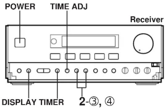
③ At ON TIME/time setting mode
["ON TIME" appears on the display, and soon it is changed to a time setting mode.] Set to the time when the timer play begins by using the HOUR button and the MINUTE button.
④ At OFF TIME/time setting mode
["OFF TIME" appears on the display, and soon it is changed to a time setting mode.] If necessary, set to the time when you want to finish the timer play (to turn this unit off) by using the HOUR button and the MINUTE button. Even if you do not set the time, it has already been set so that the timer play finishes after 1 hour.
* The TIMER button functions also in the time (ON TIME or OFF TIME) setting mode.
3 If you will not use this unit until the timer play begins, turn the power off by pressing the POWER switch or the TIMER button.
Note
If a timer play setting is made and the power is not turned off, the source set for the timer play will begin playing when the time comes in place of the source played at that time.
To cancel the timer play setting
After the timer play is finished, press the DISPLAY button to call the current time. While the current time is displayed, press the TIMER button so that "TIMER" goes out from the display.
If it is not canceled, the system will be turned on at the same time every day, so it can be used as an alarm. However, if you will be out at that time, cancel the timer play setting.
* Unless the AC supply lead is unplugged or there is a power failure for more than 30 minutes, the time set on the timer will be retained until it is reset.
How to make time setting in the ON TIME or OFF TIME mode
For the hour:
Press the HOUR button to change the hour to a higher value. Press and hold to change continuously. To change the hour to a lower value, while pressing the TIME ADJUST button, press the HOUR button.
For the minute:
Use the MINUTE button and operate it in the same way as you did to change the hour.
HOW TO USE THE BUILT-IN TIMER
CD Player
Tape Deck
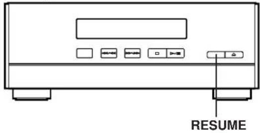
To begin CD playback from a desired track by the timer play.
- Play back the track which you want to play back from the beginning of the timer play.
- Press the RESUME button on the CD player so that “ ”V appears on the display.
- Make the timer play setting.
- Turn the power off while the track is being played back. when the time comes, the timer play begins from the beginning of the track.
* If you will not play back a CD from a designated track by the timer play, press the RESUME button so that "V disappears from the display.
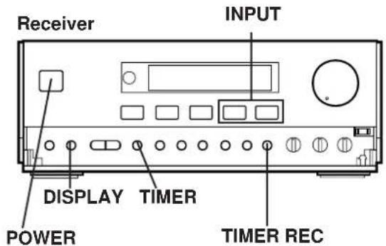
Timer recording (To record a tuner program)
1 Load a blank tape into the DECK B cassette compartment.
2 Tune to the station of which program you want to record.
3 Follow step 2 of the "Timer play" on pages 38 and 39.
* In step 2-②, select "TUNER" by pressing the INPUT selector of button, and then press the TIMER REC button so that "REC" and the station frequency flashes alternately.
4 If desired, change the setting of the reverse mode switch and the Dolby NR switch.
5 If you will not use this unit until the timer recording begins, turn the power off by pressing the POWER switch or the TIMER button.
To confirm the timer time setting
Press the DISPLAY button.
To cancel the setting of timer recording
Press the DISPLAY button once or more so that "REC" flashes on the display. While "REC" is flashing, press the TIMER REC button.
* Unless the AC supply lead is unplugged or there is a power failure for more than 30 minutes, the time set on the timer will be retained until it is reset.
Note
When the timer recording is finished, the timer setting is automatically canceled to avoid repeating timer recording of the same setting.
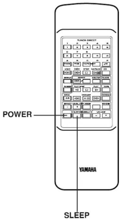
Sleep timer operation
This unit can be turned off automatically.
1 Play the desired sound source.
2 Press the SLEEP button. "SLEEP" appears on the display, and soon it is replaced by "120".
3 Press the SLEEP button repeatedly until the desired sleep time appears in the display. The display will change as described below. (Time is displayed by the minute.)
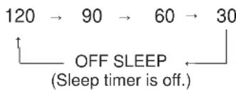
flowchart
graph TD
    A["120"] --> B["90"]
    B --> C["60"]
    C --> D["30"]
    D --> E["OFF SLEEP\n(Sleep timer is off.)"]
* The original display mode will resume about 4 seconds after the selection is made.
* The SLEEP indicator illuminates to indicate that the sleep timer is on.
4 The unit will turn off automatically when the preset sleep time has passed.
To confirm the sleep time setting
Press the SLEEP button once. "SLEEP" appears on the display, and soon it is replaced by the remaining time of the preset sleep time.
To change the sleep time
While the SLEEP indicator illuminates, press the SLEEP button repeatedly until the desired time appears.
To stop the sleep timer operation
Press the POWER switch, or press the SLEEP button repeatedly until "OFF SLEEP" appears on the display. (The SLEEP indicator will go out.)
To set the sleep time using front panel buttons
First press the DISPLAY button to display the current time. Within 7 seconds, press the AUTO MEMORY button. Whenever the AUTO MEMORY button is pressed, the sleep time changes.
Using the timer and the sleep timer at the same time
1 Prepare timer playback. (See pages 38 and 39.)
* Do not turn the power of this unit off after the timer setting is finished.
2 Press the SLEEP button and set the sleep time.
When the sleep timer operation finishes, the timer will function to turn the source on at the preset time.
Notes
- Do not set the timer time so that the timer will start during sleep timer operation. (Since sleep timer operation has priority, the timer will not operate.)
- If the power is turned off by the sleep timer while playing back a CD with “Vs illuminated on the display, when CD playback begins at the time set on the timer play setting, playback begins from the beginning of the track which had been being played back when the power was turned off by the sleep timer.
* The “ ” indicator is switched on and off by pressing the RESUME button on the CD player.
USING EXTERNAL UNITS
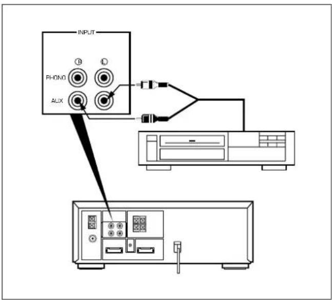
Auxiliary (AUX)
1 Connect the output lead of a video cassette player, video disc player, etc. to the AUX inputs of this unit.
(red → right channel, white → left channel)
2 Press the INPUT selector or button once or more until "AUX" appears on the display.
3 Operate the unit connected to the AUX inputs.
4 Start recording with this unit, if so desired. (See page 36.)
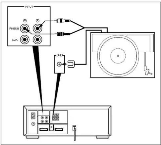
Turntable (PHONO)
1 Connect the output lead of a turntable. (red → right channel, white → left channel)
2 Connect the GND lead of a turntable.
3 Press the INPUT selector of button once or more until "PHONO" appears on the display.
4 Operate the turntable.
5 Start recording with this unit, if so desired. (See page 36.)
USING EXTERNAL UNITS
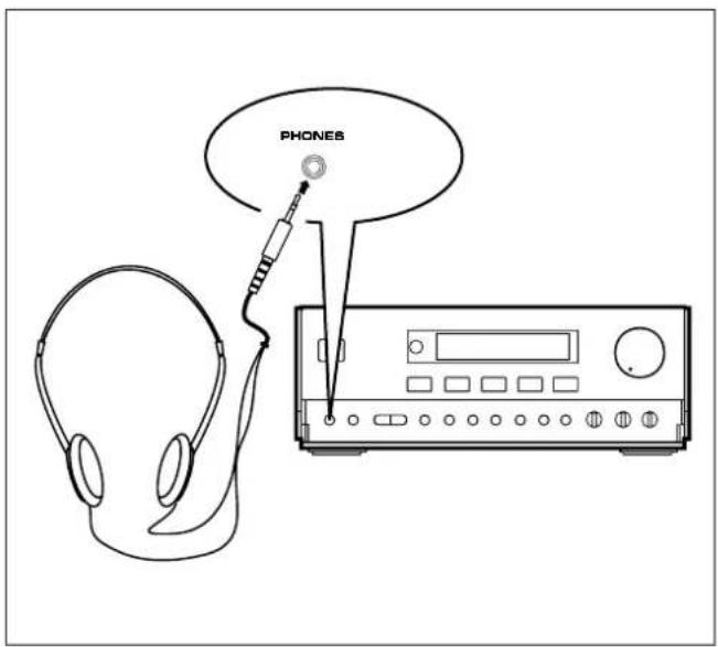
Headphones
- Be sure that your headphones have a 3.5 mm (1/8") diameter plug and are between 16 ohms and 50 ohms impedance. Recommended impedance is 32 ohms.
- When headphones are connected, the speakers are defeated automatically. Adjust the VOLUME control for desired volume.
MAINTENANCE
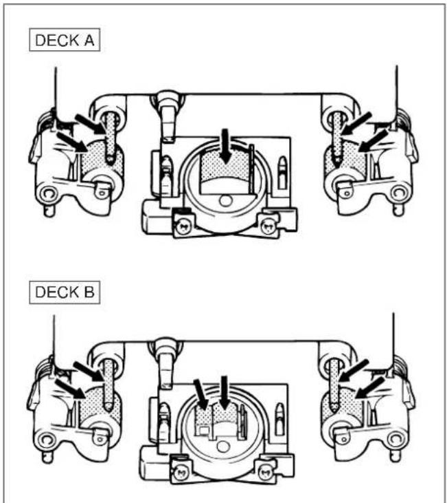
Internal care
- Dirty heads, capstans and pinch rollers can cause poor sound and tape jams.
Clean these parts with a cotton swab moistened with commercially available head/pinch roller cleaner or isopropyl alcohol, or with a commercially available cleaning tape. - After long use, the deck's heads and capstans may become magnetized, causing poor sound. Demagnetize these parts once every 30 hours of playing/recording time by using a commercial tape head demagnetizer. Read the demagnetizer's instructions carefully before use.
External care
- Periodically clean the surfaces of this system, especially the top panel of the receiver to prevent the ventilation holes from being blocked with dust etc.
- Do not use chemically treated cleaning cloths or other chemicals. (See "Precautions".)
SPECIFICATIONS
As a part of policy of continuous improvement, YAMAHA reserves the right to make design and specification changes for product improvement without prior notice. The performance specification figures indicated are nominal values of production units.
■ Receiver (RX-S50)
Minimum RMS Output Power per Channel
6 ohms, 50 Hz to 20 kHz, 0.08% THD 35W+35W
6 ohms, 1 kHz, 10% THD
[U.K. and General models only] 50W+50W
DIN Standard Output Power per Channel [Europe model only]
6 ohms, 1 kHz, 1% THD 40W
IEC Power [Europe model only]
6 ohms, 1 kHz, 0.1% THD 35W
Input Sensitivity/Impedance
PHONO MM 2.5 mV/47 k-ohms
AUX 300 mV/20 k-ohms
Headphone Output Impedance 68 ohms
Total Harmonic Distortion (20 Hz to 20 kHz)
AUX to SP OUT (17.5W/6 ohms) 0.08%
Tone Control Characteristics
BASS: Boost/cut ±10 dB (50 Hz)
TREBLE: Boost/cut ±10 dB (20 kHz)
Tuning Range
FM
[Australia, Europe, U.K. and General models]
87.5 to 108.0 MHz
AM (MW)
[General model] 530 - 1,710 kHz
[Australia, U.K. and Europe models] ..... 531 – 1,611 kHz
LW
[U.K. and Europe models only] 153 - 288 kHz
Usable Sensitivity
FM (75 ohms)
(30 dB S/N Quieting, 1 kHz, 100% mod.)
[Except Europe model]....1.2 ∝ V (12.8 dBf)
(DIN, Mono, S/N 26 dB) [Europe model] 1.5 ∝ V
AM (MW) 280 μV/m
LW 560 μV/m
Power Supply
[Australia and U.K. models] AC 240V, 50 Hz
[Europe model] AC 230V, 50 Hz
[General model] AC 110/120/220/240V, 50/60 Hz
Power consumption
[Australia, Europe, U.K. and General models] 120W
Dimensions (W x H x D).... 280 x 107.5 x 339.5 mm
(11" x 6-7/8" x 13-3/8")
Weight 5.3 kg (11 lbs. 11 oz.)
■ CD player (CDX-S50)
Power Source AC supplies from receiver unit
Type .... Compact Disc Player
Signal Readout
Non-contact, 3-beam semi-conductor laser pick-up
D/A Converter 1-bit DAC
Filter 8-time oversampling 18-bit digital filter
Wow and Flutter ....Below measurable limits
Dimensions (W x H x D).... 280 x 107.5 x 322.5 mm
(11" x 6-7/8" x 12-11/16")
Weight 3.0 kg (6 lbs. 10 oz.)
■ Tape Deck (KXW-S70)
Power Source AC supplies from receiver unit
Type ...... Auto Reverse 4-Track 2-Channel playback/recording and playback stereo double Cassette Deck
Heads PB, REC/PB : Hard Permalloy
Erase : Double Gap Ferrite
Motors ...... DC servo motor x 2
Wow and Flutter ±0.19%, W.PEAK
0.09%, W.RMS
Fast Winding Time (C-60 Tape) .... About 120 seconds
Frequency Response (-20 dB)
30 - 15,000 Hz ± 3 dB (Normal)
30 - 16,000 Hz ± 3 dB (CrO _2 )
30 - 18,000 Hz ± 3 dB (Metal)
Signal-to-Noise Ratio 58 dB (Dolby NR OFF)
66 dB (Dolby B NR ON)
74 dB (Dolby C NR ON)
Harmonic Distortion ...... No more than 1.2%
Channel Separation (Input Shorted 1 kHz)
More than 40 dB
Crosstalk (Input Shorted 125 Hz)...... More than 55 dB
Dimensions (W x H x D).... 280 x 117.5 x 326 mm
(11" x 4-5/8" x 12-13/16")
Weight 4.2 kg (9 lbs. 4 oz.)
■ Speaker (NX-S50)
Type ...... Active Servo Processing type
Speakers 13 cm (5-1/8") woofer
5 cm (2") tweeter
Frequency Range 50 - 20,000 Hz
Sound Pressure Level 88.5 dB
Maximum Power Handling Capacity.... 50W
Impedance 6 ohms
Dimensions (W x H x D) 170 x 332.5 x 222 mm
(6-11/16" x 13-1/16" x 8-3/4")
Weight 3.3 kg (7 lbs. 4 oz.) x 2
TROUBLESHOOTING
If your unit fails to operate normally, check the following points to determine whether the fault can be corrected by the simple measures suggested. If it cannot, or if the fault is not listed in the SYMPTOM column, disconnect the power cord and contact your authorized YAMAHA dealer or service center for help.
Should be service required, the servicer will need all three pieces (RX-S50, CDX-S50, KXW-S70).
| SYMPTOM | CAUSE | REMEDY | |
| RECEIVERCD PLAYER | No power even if the POWER switch is pressed. | AC supply lead is not plugged in. | Plug in the AC supply lead. |
| No sound from one speaker | Loose speaker connections. | Connect properly. | |
| No sound from speakers. | Internal protection circuit is functioning. | Unplug the AC supply lead from the wall AC outlet, and then plug in again. | |
| Excessive static in FM broadcasts. | Interference from starting motor of nearby car. | Position the FM antenna as high and as far away from nearby roads as possible. Connect using a coaxial cable. | |
| Interference from thermostat of nearby electrical appliance. | |||
| Noise increases during stereo broadcasts. | Antenna input is too weak due to obstructions or excessive distance from broadcasting station. | Check antenna connections. | |
| Install a multi-element type FM antenna if possible. | |||
| Stereo broadcasts are noisy and STEREO indicator blinks on and off. | Insufficient antenna input. | Install an antenna appropriate for the electric field strength of your area. | |
| Cannot select preset stations. | Preset memory has been erased. | Reprogram memory presets. | |
| Buzzing or static during AM (LW or MW) broadcasts. | Interference from source such as lightning, flourescent lights, electric motors or thermostat of nearby electrical appliance. | Problem is difficult to eliminate but can be lessened by grounding MW/LW (AM) loop antenna. | |
| TV or microprocessor is being used nearby. | Move away from TV or microprocessor. | ||
| AM (LW or MW) broadcast sensitivity is poor. | Radio signal is weak or antenna is not properly connected. | Properly connect MW/LW (AM) loop antenna. | |
| Change orientation of MW/LW (AM) loop antenna. | |||
| Install an external MW/LW (AM) antenna. | |||
| Can't set timer. | Current time is not set. | Set current time. | |
| This unit will not operate properly. | The internal microcomputer has been frozen by an external electric shock (lightning, excessive static electricity, etc.) or power supply with low voltage. | Unplug the AC supply lead from the wall AC outlet, and then plug in again after about one minute. | |
| TAPE DECK | Play does not begin even if disc is loaded. | Disc is upside down. | Load disc label side up. |
| Disc is dirty. | Clean disc. | ||
| No sound. | Input selector setting is incorrect. | Select "CD" by the INPUT selector buttons. | |
| Sound stops suddenly (always at same spot). | Disc is dirty. | Clean disc. | |
| Volume set too high. | Lower volume. | ||
| Tape won't move during playback or recording. | Slack tape wrapped around pinch roller. | Take up slack with a pencil before using. | |
| Can't record. | Erasure prevention tab is broken off. | Replace tape or cover erasure prevention hole with cellophane tape. | |
| Head is dirty. | Clean heads. | ||
| Sound is distorted or fades out. | Head is dirty. | Clean heads. | |
| Head has become magnetized. | Demagnetize heads with head eraser. | ||
| Tape is worn. | Replace tape. | ||
| Poor sound quality. | Dolby NR switch is set to wrong position. | Set to positions matching those used when tape was recorded. | |
| Stereo balance is poor. | Head is dirty. | Clean heads. | |
| Excessive noise. | Head is dirty. | Clean heads. | |
| Head has become magnetized. | Demagnetize heads with head eraser. | ||
| Tape is worn. | Replace tape. | ||
| Tape travel stops in middle of playback or recording. | Slack tape coming out of cassette shell. | Take up slack by turning reels with a pencil. | |
| Tape is creased or torn. | Replace with new tape. | ||
| Endless tape is being used. | Don't use endless tapes. | ||
| Can't find the beginning of desired selections on tape. | Silent gaps between selections are too short. | The function for searching the beginning of desired selections won't operate unless the silent gaps between selections are at least four seconds long. | |
| Excessively soft passages in middle of selections. | |||
| Conversation etc. is recorded. | |||
| REMOTE CONTROL | Remote control doesn't work. | Batteries are dead. | Replace batteries. |
| Remote control is too far away or is being used at incorrect angle. | Use within 6 m and 60° radius. | ||
| Direct sunlight or lighting (of an inverter type of fluorescent lamp etc.) is striking the remote control sensor of the main unit. | Change position of the main unit. | ||
| TV functions strangely when the remote control is used. | Remote control is being used near TV set with a remote control sensor. | Move TV farther away or cover its remote control sensor. |