Vengeance 280 FPV Racer - Drone Hyperion - Free user manual and instructions
Find the device manual for free Vengeance 280 FPV Racer Hyperion in PDF.

| Product Type | FPV Racing Drone |
| Model | Vengeance 280 FPV Racer |
| Brand | Hyperion |
| Wheelbase | 280 mm |
| Dimensions (LxWxH) | 280 x 280 x 80 mm (approx.) |
| Weight (without battery) | 350 g (approx.) |
| Frame Material | Carbon Fiber |
| Motor Type | 2206 2300KV Brushless |
| ESC | 30A 4-in-1 BLHeli_S |
| Flight Controller | Betaflight F4 (or similar) |
| Propeller Size | 5x4.5 inch (tri-blade) |
| Battery | 4S LiPo 1300-1800 mAh |
| FPV Camera | 600TVL CMOS (or equivalent) |
| Video Transmitter | 5.8 GHz 25-200mW |
| Radio Receiver | PPM/SBUS compatible (not included) |
| Flight Modes | Acro, Horizon, Angle, Air Mode |
| Maximum Speed | Up to 120 km/h (measured) |
| Flight Time | 3-5 minutes (aggressive flying) |
| Control Range | Up to 1 km (with optimal conditions) |
| Assembly Level | BNF (Bind-and-Fly) or Kit |
| Recommended for | Intermediate to Advanced pilots |
| Maintenance | Regular cleaning, motor bearing check, firmware updates |
| Safety Notes | Disconnect battery before maintenance; propellers are sharp |
| Spare Parts Availability | Arms, motors, ESCs, frames widely available |
Frequently Asked Questions - Vengeance 280 FPV Racer Hyperion
User questions about Vengeance 280 FPV Racer Hyperion
0 question about this device. Answer the ones you know or ask your own.
Ask a new question about this device
Download the instructions for your Drone in PDF format for free! Find your manual Vengeance 280 FPV Racer - Hyperion and take your electronic device back in hand. On this page are published all the documents necessary for the use of your device. Vengeance 280 FPV Racer by Hyperion.
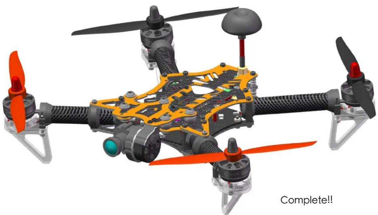
USER MANUAL Vengeance 280 FPV Racer Hyperion
●Fully Assembled: No building or firmware loading necessary!
● On-Screen Display (OSD): Program or set up your Vengeance on-the-fly, no computer needed.
●In-Flight-Adjustable Single-Axis Camera Gimbal, Self-leveling during flight.
●Vibration Dampened Second-Camera Mount.
●Robust, Pure Carbon-Fiber Frame with Carbon Exoskeleton Reinforcements.
●Stress-Flex Designed to Withstand Impacts, Mass centralized for high-rate turning.
●Black-Anodized, High-Strength CNC Aluminum Boom Mounts.
●Tough, Translucent Polymer Landing Legs with Built-in Directional Red-Green LED.
- 8° Forward-Tilt Motor Mounts for Aerodynamic Efficiency and Top Speed Performance.
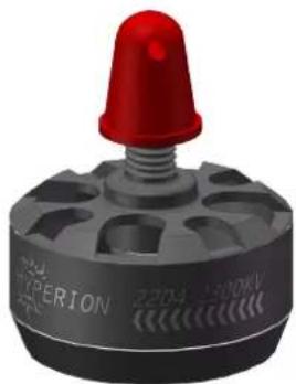
●Four 2204, 2300Kv High-Output Brushless Motors.
●Custom Compact BL-Heli 20A Motor Controllers (ESC).
●Visual LED Flight Mode Indicator. Easy to confirm your flight mode.
●Pre-loaded with Three Flight Modes: Normal, Altitude Hold, or Acro Mode.
●NAZE Spec 32 Bit Flight Controller 7DOF (with BMP sensor).
● Altitude Hold via Integrated Barometric Pressure Sensor (BMP).
●3S and 4S Battery Compatible. Hyperion G6 HV LiPo Suggested.
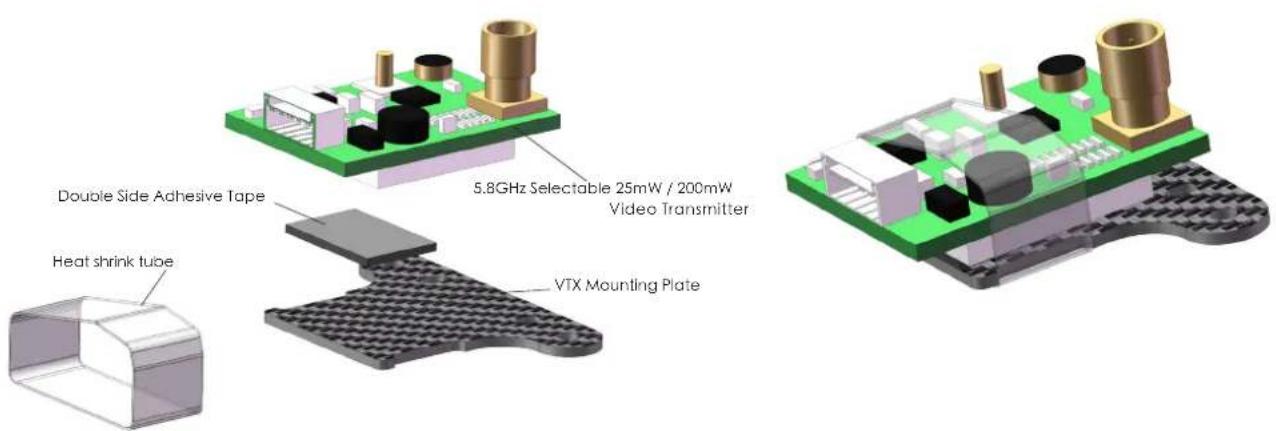
● 5.8GHz Auto-Scan 40CH Video Transmitter (VTX) w/ Race Band VTX selectable for either 25mw/200mw output.
●Tuned 5.8GHz CloverLeaf Skew-Planar Antenna.
●Plug-n-Play Ready for Optional GPS modules.
●Built-in Low-voltage Audible Alarm.
- Compatible with Single Wire* or Traditional Receivers (*S-Bus, Horizon Spektrum™ Satellite, or Hyperion Compatible receivers).
●Box includes Carry Handle and Foam Racer Cradle + Parts Holder, for service as field case.
●One Set 6x4 CC/CCW Propellers Included.
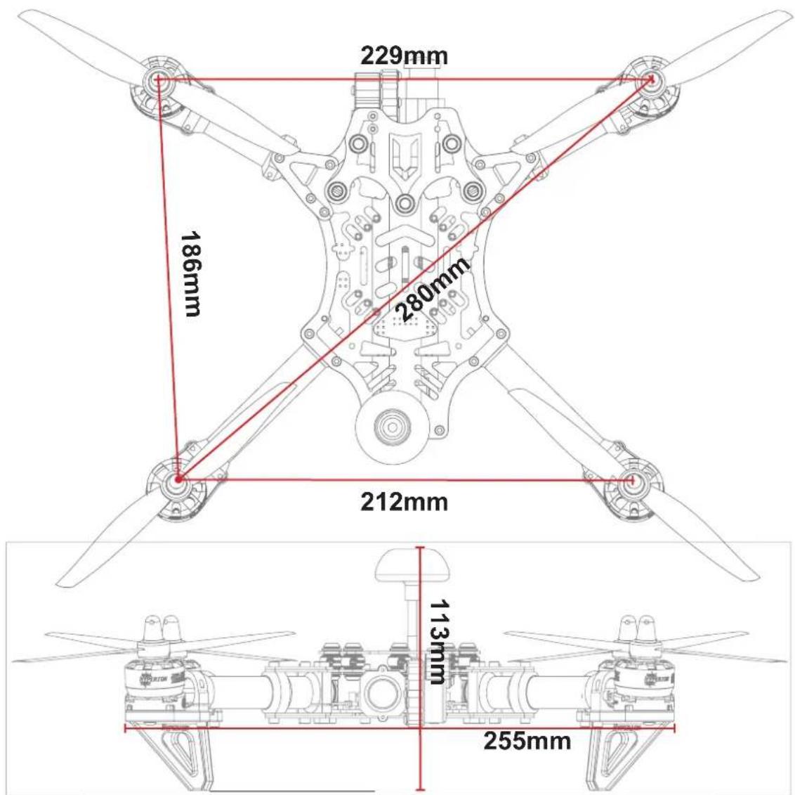
Specifications
| ○ Length : 216mm Channels : 6~8ch Motors : Hyperion 2204-2300kV□ | |
| ○ Width : 255mm Camera : 600tvl 1/3" CMOS Camera ESC : BL Heli 20A | |
| ○ Diagonal Base : 280mm | VTX : 5.8Ghz 25-200 0mW selectable w/ 40Ch's |
| ○ Weight : 435g (w/o battery) | Battery : 3~4S Compatible |
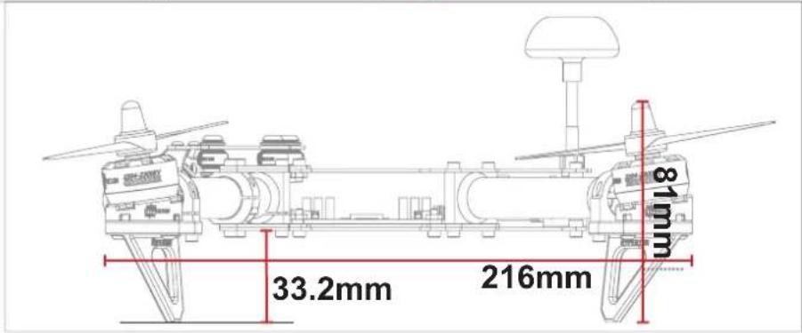
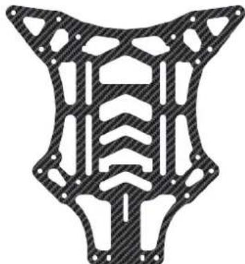
Left / Right Reinforcement Plate
Main Carbon Fibre Frame

natural_image
Symmetrical mechanical component diagram with orange and black patterned sections (no text or symbols)Camera Mounting Plate

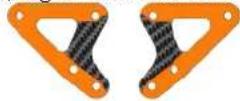
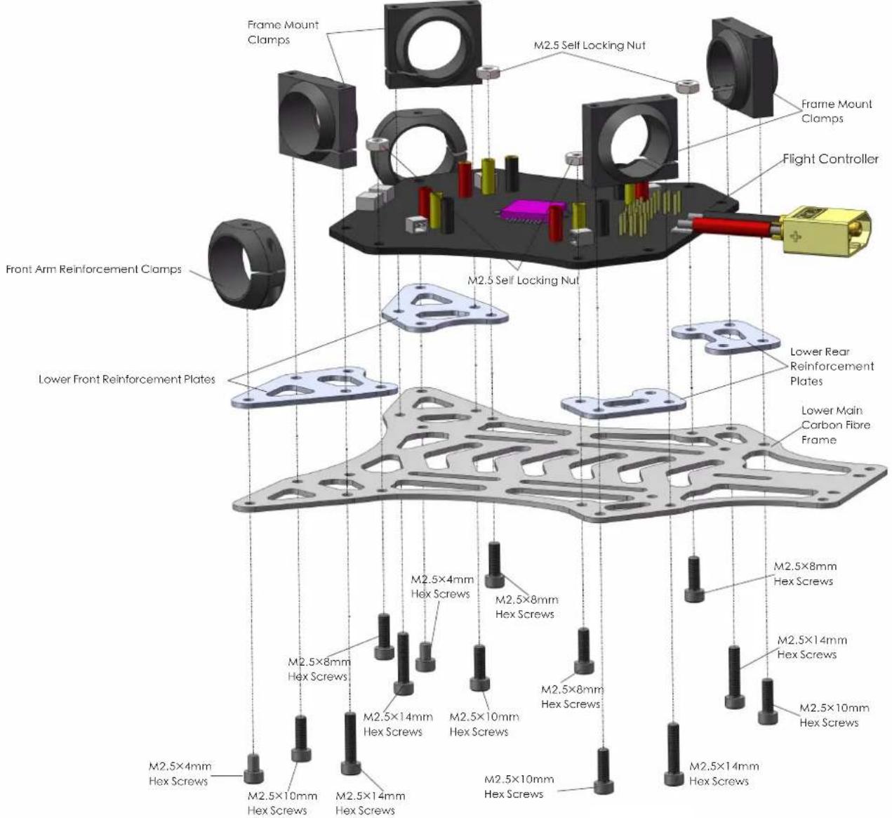
Lower Front Reinforcement Plates
Lower Main Carbon Fibre Frame
natural_image
Abstract geometric pattern with symmetrical cutouts and hatched fill (no text or symbols)Lower Rear Reinforcement Plates
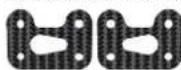
VTX Mounting Plate
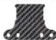
▲Vengeance Carbon Fiber Frame Kit
natural_image
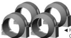
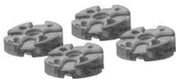
Four identical gray 3D-rendered mechanical components arranged in a staggered pattern (no text or symbols visible)◀ Main Frame Mounting Clamps ×4
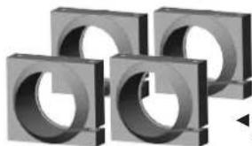
natural_image
3D rendered mechanical parts with no visible text or symbols◀ Motor Mounting Clamps ×4
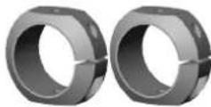
◀ Front Arm Reinforcement Clamps ×2
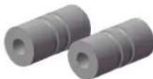
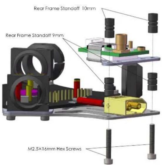
▲Rear Frame Standoff 9mm×2
▲Rear Frame Standoff 10mm×2
natural_image
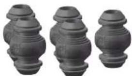
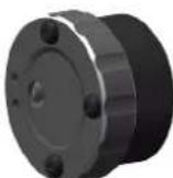
Three identical gray cylindrical objects with stepped surfaces, arranged side by side (no text or symbols visible)▲ Hyperion Silicon Dampeners Soft ×5

▲6x4 CW + CCW Prop Set (Black)

▲6x4 CW + CCW Prop Set (Orange)
natural_image
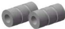
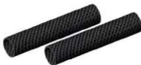
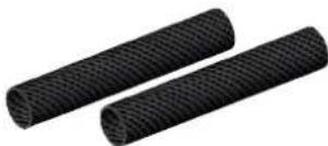
Two black cylindrical objects with textured surfaces, no visible text or symbols▲Rear Arms Tubes 15×83mm ×2▲Front Arm Tube
natural_image
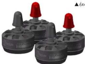
Four gray plastic mechanical components with red caps, arranged in a row (no text or symbols visible)▲Hyperion 2204-2300kv Brushless Motor CW ×2 Hyperion 2204-2300kv Brushless Motor CCW ×2
natural_image
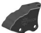
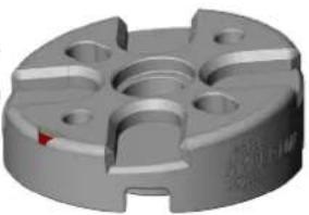
Four metallic mechanical components with circular cutouts, shown in grayscale (no text or symbols visible)▲Eight Degree Forward Tilt Motor Mounts ×4
natural_image
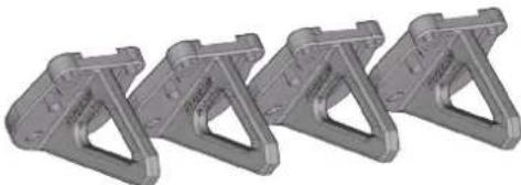
Four identical gray metal bracket components arranged in a row (no text or symbols visible)▲Vengeance Translucent Landing Gear×4
natural_image
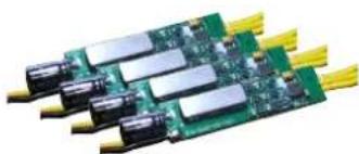
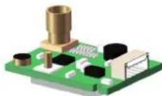
Close-up of a green printed circuit board with multiple black connectors and yellow leads (no visible text or symbols)▲BL Heli 20A 2S\~4S ESC ×4
▲5.8GHz Cloverleaf RHCP Antenna (RP-SMA)
▲5.8 GHz Selectable 25mW / 200mW Video Transmitter
natural_image
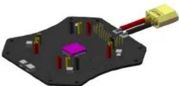
3D diagram of a microchip or electronic component with pins and connectors, no visible text or symbols▲ Flight Controller with OSD, and Altitude Sensor
natural_image
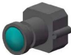
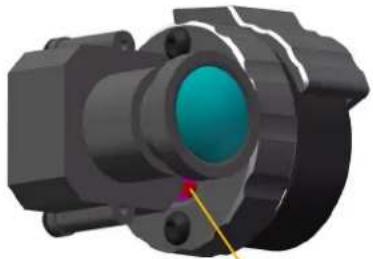
3D rendering of a black rectangular object with a teal lens, resembling a camera or connector (no text or symbols visible)▲1/3" 600tvl CMOS Camera
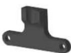
▲Camera Mount▲
Bracket
Vengeance Gimbal Motor with Sensor (1-axis Pitch)
▲Gimbal Mount Bracket
▲LED Landing Gear PCB (Red)
▲LED Landing Gear PCB (Green)
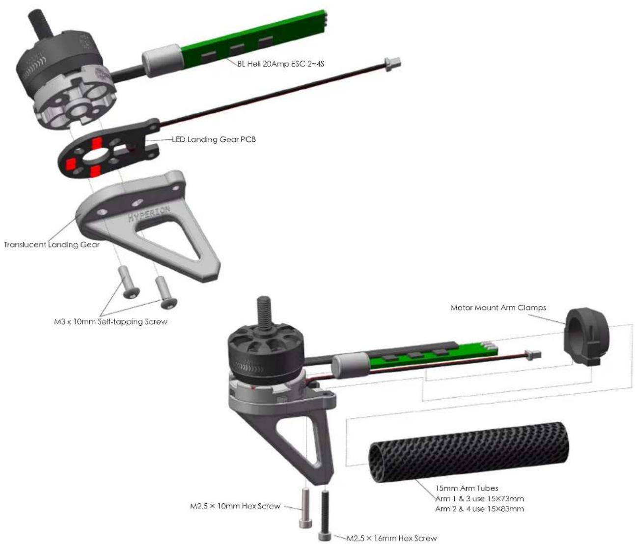
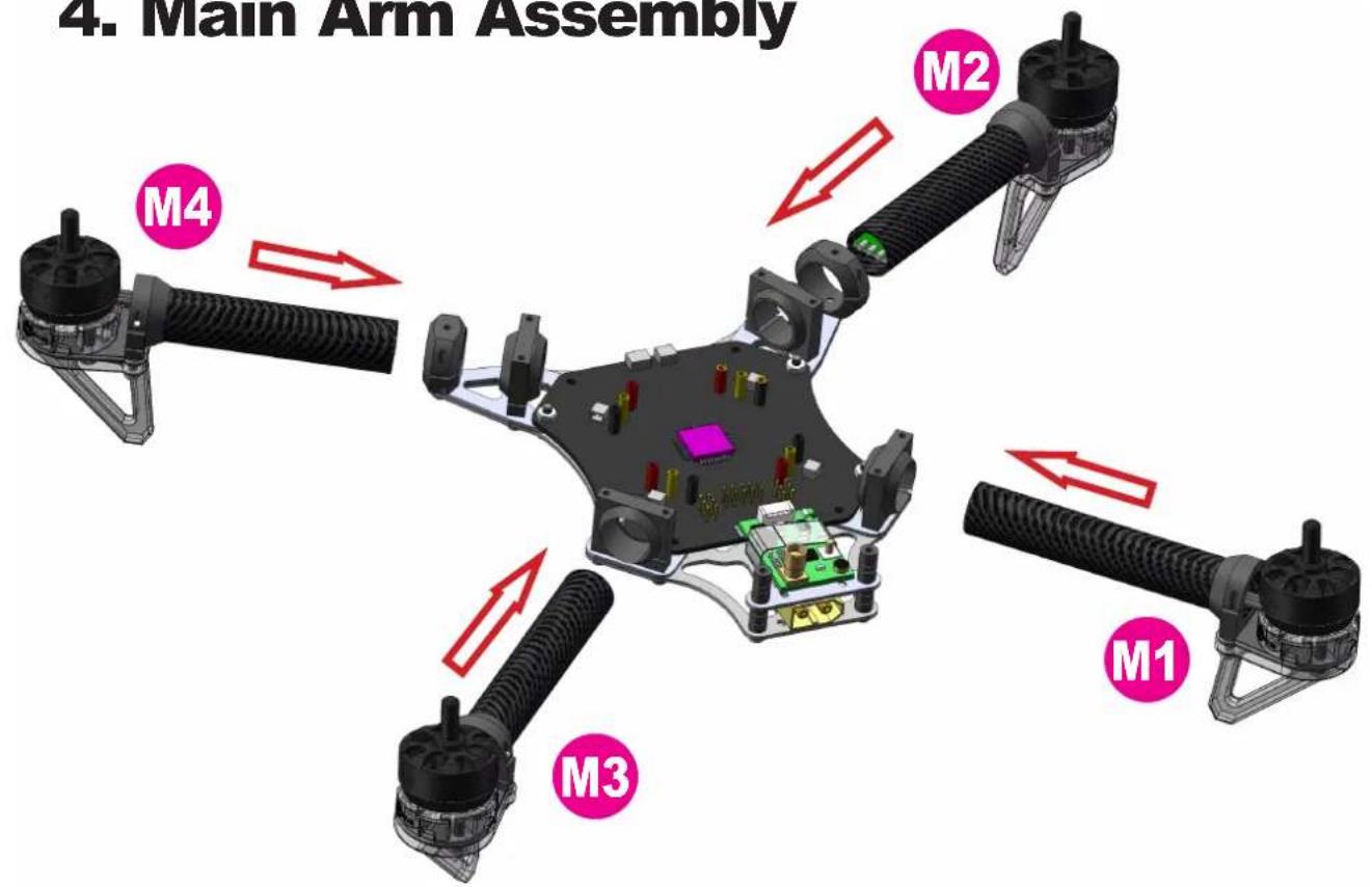
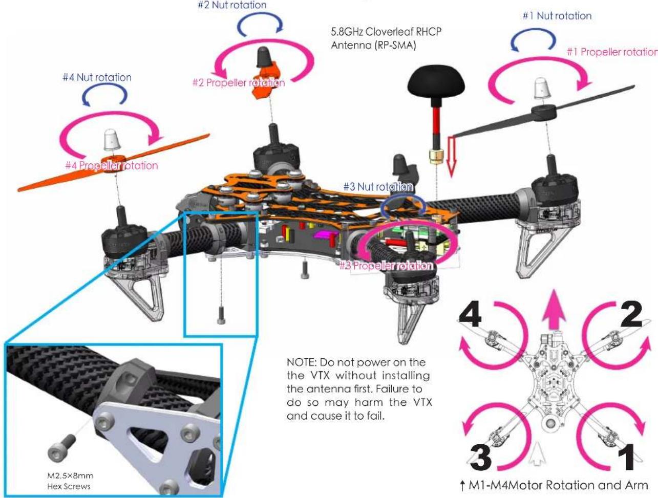
1.Motor & Arm
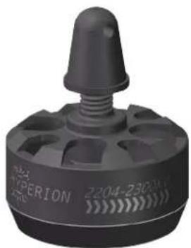
The Vengeance's unique motor mount design allows for superb forward flight and cornering performance. Please note that during installation that you install each arm in the proper location and the angle of motors and motor rotation corresponds to the picture enclosed.
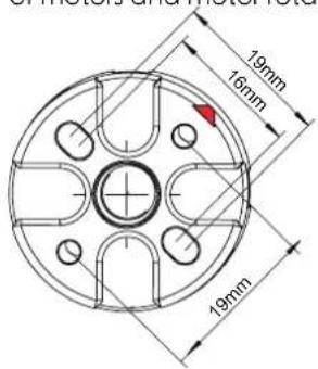
Motor mount arrows indicated forward position of the motor. →
natural_image
3D rendered mechanical part with circular features and central hole (no text or symbols)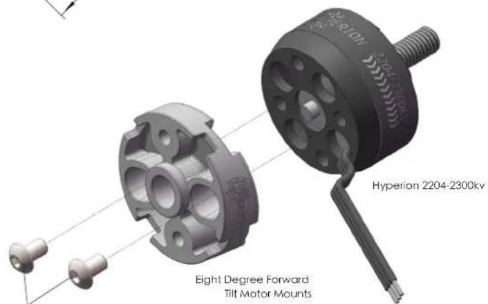
M3×6mm Hex Screws
natural_image
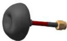
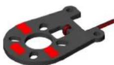
Close-up of a red and black industrial component with a conical top (no visible text or symbols)▲Clockwise Rotation <<<< Motor Rotation Indicators.
natural_image
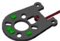
Close-up of a black industrial sensor component with a conical top and perforated base (no visible text or symbols)▲ Counterclockwise Rotation >>>> Motor Rotation Indicators.
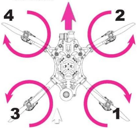
flowchart
graph TD
    A["1"] --> B["2"]
    B --> C["3"]
    C --> D["4"]
    D --> A
    style A fill:#f9f,stroke:#333
    style B fill:#bbf,stroke:#333
    style C fill:#bfb,stroke:#333
    style D fill:#ffb,stroke:#333
↑ 1-4 Motor Rotation Chart.
Motor Mount Assembly ↗
Direction Chart.
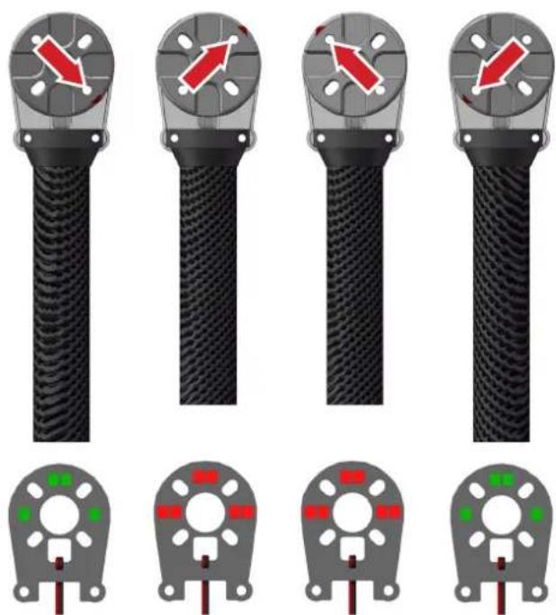
LED Landing Gear Assembly Chart→
natural_image
Four identical black cable connectors with red directional arrows on their heads, shown from different angles (no text or symbols)13 24
2.VTX Assembly
3.Main Frame Assembly
natural_image
Close-up of a black electronic circuit board with visible components and wiring, no readable text or symbols present.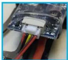
natural_image
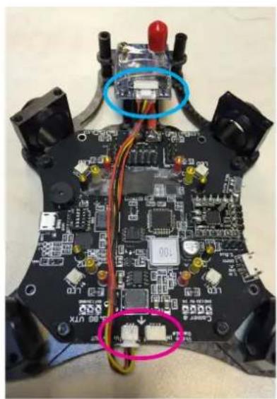
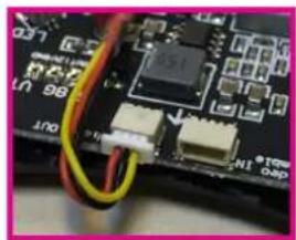
Close-up of a mechanical component with visible wiring and internal components (no text or symbols)NOTE: use the "Video Out" plug to connect to your VTX. "Video IN" plug is used to connect to the Camera.
natural_image
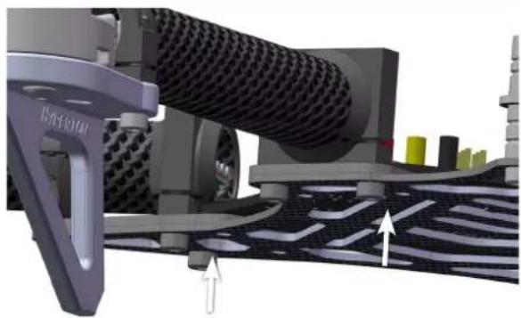
Close-up of a circuit board with electronic components and wiring (no readable text or symbols)4. Main Arm Assembly
natural_image
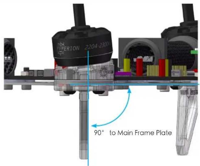
3D rendering of a car wheel assembly with mesh material and directional arrows indicating motion (no text or symbols)←Make sure that the landing gear plate is 90° to the main frame plate.
Once you have confirmed the landing gear plate is 90° to the main frame plate you can then fasten the clamp screw.
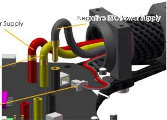
Positive ESC Power Supply
Negative ESC Power Supply
PWM Throttle Signal Wire
→Before Flying make sure your wires are correctly plugged into the proper color receptacle. Insert the LED Landing Gear Light Indicator in the plug.
5. Camera Mounting Assembly
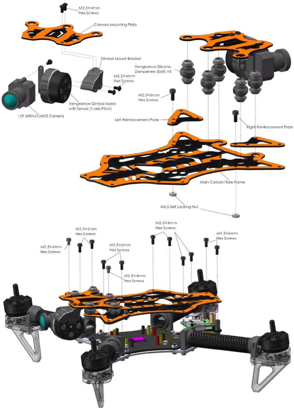
6. Frame Final Assembly
natural_image
3D rendering of a quadcopter drone with visible propellers and internal structure (no text or symbols)7. Vengeance Flight Controller Details
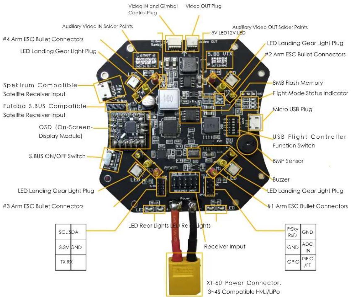
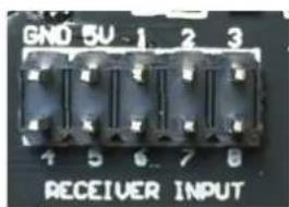
This is the PWM Input Receiver Channel Chart. Plug each corresponding servo lead into the correct channel with the correct polarity. After wire installation has been
made please make sure to check in CleanFlight Software that your "Channel Map" is consistent with your brand of Transmitter. DO NOT ARM Vengeance with propellers on for the first time without checking!
Receiver Connection

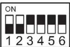
Flight Controller Function Switch
Flight Controller Programming & Upgrade
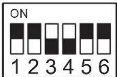
OSD Programming & Upgrade
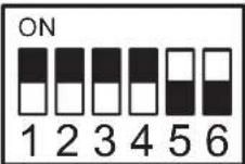
Flight Mode (must be selected for flight)
8. SetUp CleanFlight.
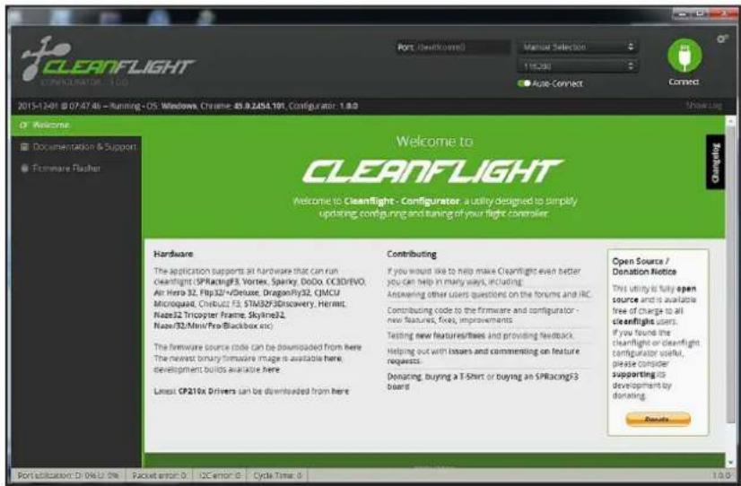
Download Google Chrome Browser, go to Chrome Application Webstore and download "CleanFlight" and install it.
If it is your first-time installation of Cleanflight you must click "Here" to download and install "CP210X Drivers"
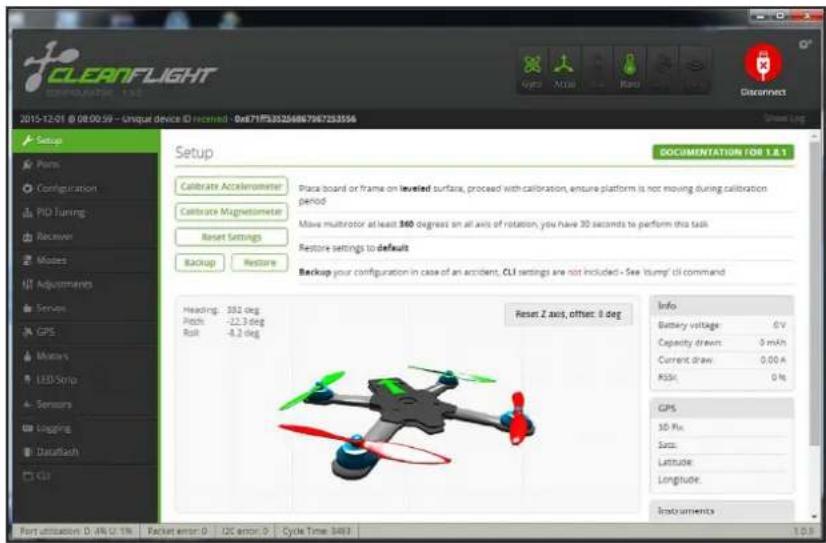
After properly connecting the Vengeance via the Micro USB plug to CleanFlight Software the program should resemble your quadcopters position.
Here is the Main Menu options page. You may Calibrate and update your flight parameters and other settings. You can also update and backup your flight controller settings.
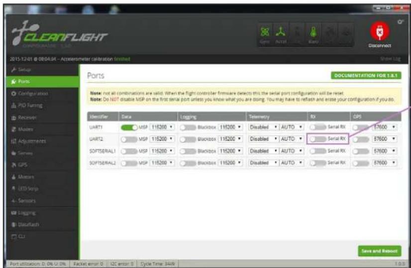
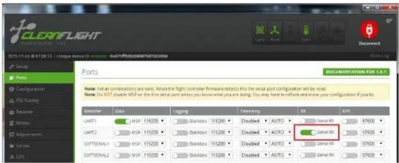
By default select UART1 for standard PWM input Receivers.
When using Spektrum or other PPM input receivers you must select UART2 Serial RX and turn ON
DO NOTE! You must "Save and Reboot" to save changes onto your flight controller.
![CLEANFLIGHT CONFIGURATION - I.E.O. 2015-12-01 @ 08/04-04 - Accelerometer Calibration Finished Setup Point Configuration PID Tuning Receiver Modes Adjustments Series GPS Motors LED Strip Sensors Unipling DataRash CLZ Configuration Note: Not all combinations of features are valid. When the flight controller firmware detects invalid feature combinations conflicting features will be installed. Note: Configure serial ports before enabling the features that will use the ports. Mixer Quad X ESC/Motor Features MOTOR_STOP Don't spin the motors when armed ONESHOT125 ONESHOT ESC support (disconnect ESCs, remove propri) Disarm motors regardless of throttle value (When arming via AUX channels) Disarm motors after on expiry(Seconds) (Requires MOTOR_STOP Navian) 1060 Minimum Thristle 1500 Middle Thristle (RC inputs central value) 1860 Maximum Thristle 1000 Minimum Command Board Alignment Roll Adjustment [deg] Pitch Adjustment [deg] Yaw Adjustment [deg] Accelerometer Trim 0 Accelerometer Roll Trim 0 Accelerometer Pitch Trim Receiver Mode RX_PFM RPM RX input RX_SERIAL Serial-based receiver GPS(RAT, SDUS, SUMD) RX_PARALLEL_PWM PWM RX input RX_MSP MSP RX input Serial Receiver Provider Note: Remember to configure a Serial Port (via Ports tab) and choose a Serial Receiver Provider when using RX_SERIAL feature. SPEKTRUM104 SPEKTRUM2048 SBUS SUMD Receiver failsafe TALSAFE Failsafe settings on RX signal loss 1000 Failuate Thristle RSSI (Signal Strength) RSSI_ADC Analog RSSI Input Bacteria Voltage VBAT battery voltage monitoring 3.3 Minimum Cell Voltage 4.3 Maximum Cell Voltage 3.5 Warning Cell Voltage 110 Voltage Scale Current Sensor CURRENT_METER Battery current monitoring 400 Scale the output voltage to inillamps (1/10h mV/3) 0 Offset in milli-watt steps Enable support for legacy Multim DSP current output. System configuration Note: Changing this may require PID re-rating. 3000 Flight Controller Loop Time 266 Cycles/SEC (HD) GPS Note: Remember to configure a Serial Port (via Ports tab) when using GPS feature. GPS Configure port scenario first NMEA Protocol Auto-detect Ground Assistance Type Magneto meter Declination [deg] Other Features INFLIGHT_ACC_CAL In-flight wave calibration SERVO_TILT Servo gymmur SOFTSERIAL Evate CPU-based serial ports SONAR Sonar TELEMETRY Telemetry output 3D 3D mode (for use with reversible ESCs) LED STRIP Addressless RGB LED strip support DISPLAY OLED Screen Display BLACKBOX Blackbox light data recorder Save and Retouch Port utilization D: 0% U: 0% Backer error 0 12C error 8 Cycle Time 3410](/content/2026/05/1032879/images/5a59a7f5fb8a512aa02d631fa1f79d486b4beee2ec73b76d773e596a0f56f72c.jpg)
By default the Vengeance comes loaded with all preset options. The Default parameters are to be used with standard PWM input receivers. If you would like to use a PWM or S.BUS style receiver you must configure these settings yourself.
Receiver Mode: If you are using a Satellite Receiver or PPM input you may select the type of Receiver here. For example: Spektrum PPM or Futaba S.BUS.
By default the Vengeance is setup to use standard PWM signal. The user must use a 6Ch Transmitter to utilize the Vengeances standard functions (5Ch. Flight Mode Selection, 6Ch. Gimbal Control)
"Serial Receiver Provider" option allows you to select the type of PPM (single-line) input Receiver you are using.
If you edit the Receiver Input type please make sure DO NOT ARM motors until you have verified that your "Channel MAP" corresponds to your Transmitter. Failure to do so can lead to possible bodily damage.
DO NOTE! You must "Save and Reboot" to save changes onto your flight controller.
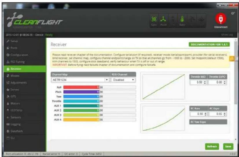
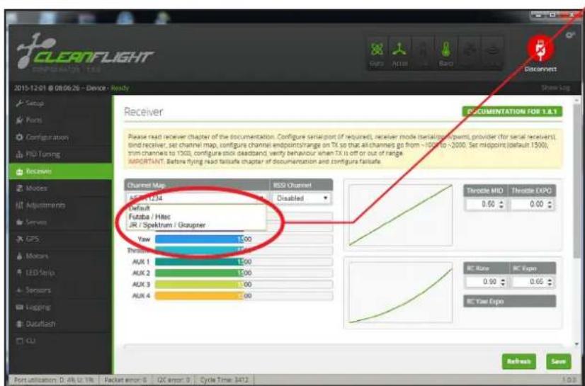
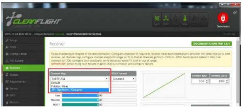
The "Receiver" directory of CleanFlight helps to show you your Channel Map and the position of your Transmitters controls with respect to the Flight Controller.
Under the "Channel Map" option please choose if you are using Futaba / Hitec or JR / Spektrum / Graupner.
DO NOTE! You must "Save and Reboot" to save changes onto your flight controller.
| Channel Map | |||
| Default | Futaba Hitec | JR Spektrum Graupner | |
| 1 Roll Roll Throttle | |||
| 2 Pitch Pitch Roll | |||
| 3 | Throttle Throttle | Pitch | |
| 4 | Yaw | Yaw | Yaw |
| 5 Aux1 | Aux1 | Aux1 | |
| 6 Aux2 | Aux2 | Aux2 | |
| 7 Aux3 | Aux3 | Aux3 | |
| 8 Aux4 | Aux4 | Aux4 | |
| Radio Channel Revers | ||||
| Futaba Hitec | JRSpektrum Graupner | |||
| 1 | Roll | Reverse | Throttle | Normal |
| 2 | Pitch | Normal | Roll | Reverse |
| 3 | Throttle | Reverse | Pitch | Normal |
| 4 | Yaw | Normal | Yaw | Reverse |
| 5 | Aux1 | Aux1 | ||
| 6 | Aux2 | Aux2 | ||
| 7 | Aux3 | Aux3 | ||
| 8 | Aux4 | Aux4 | ||
The colored indication bars in CleanFlight represent your real time channel PWM signal. Make sure to turn your Transmitter ON so you may check your trim and to
| Radio End Point / ATV Setting | ||||
| Futaba Hitec | JRSpektrum Graupner | |||
| 1 | Roll | 110/110% | Throttle | 120/120% |
| 2 | Pitch | 110/110% | Roll | 120/120% |
| 3 | Throttle | 110/110% | Pitch | 120/120% |
| 4 | Yaw | 110/110% | Yaw | 120/120% |
| 5 | Aux1 | 110/110% | Aux1 | 120/120% |
| 6 | Aux2 | 110/110% | Aux2 | 120/120% |
| 7 | Aux3 | 110/110% | Aux3 | 120/120% |
| 8 | Aux4 | 110/110% | Aux4 | 120/120% |
make sure your channels moves in the correct direction.
It is important to note that when you move your Transmitter sticks that your Transmitters Travel Adjustment (ATV) must move to less than 1100 and more than 1900. If your Transmitters Travel Adjustment is not properly setup than your Vengeance will not ARM. To ARM your Vengeance move your YAW/RUDDER stick to the Bottom and RIGHT position for 1-2 seconds. DO NOT ARM Vengeance with propellers on for the first time!
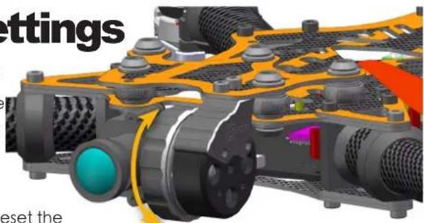
9. Gimbal Mode and Settings
The Vengeance utilizes a brushless gimbal for pitch dampening and view adjustment.
- When turning ON the Vengeance please keep the Vengeance level and do not move for about 5 seconds. The gimbal sensors must detect the horizontal position.
- Make sure that the Gimbal's wires are not tangled and are able to move freely. Failure to free the Gimbal head from obstructions may lead to the Gimbal motor to fail.
natural_image
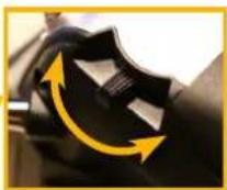
3D rendering of a mechanical component with a central blue-green circular feature and yellow pin (no text or symbols visible)Mode Change Button
- When power is plugged in on the Vengeance if the g imbalvibrates and oscillates uncontrollable then re power and power ago
- After the gimbal is set and detects horizontal positioning after 5 seconds you may rotate the gimbal with your hand desired camera view angle.
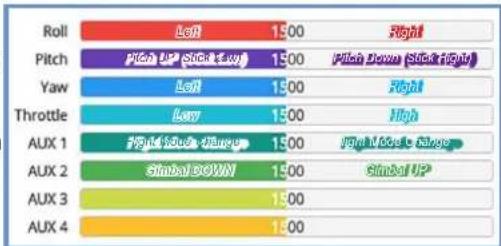
5.Ch.6 on your PWM Receiver can be used to control the Gimbal rotation UP or DOWN.
or

bar
| Category | Value | |---|---| | Roll | 1.00 | | Pitch | 1.00 | | Yaw | 1.00 | | Throttle | 1.00 | | AUX 1 | 1.00 | | AUX 2 | Global Top | | AUX 3 | 1.00 | | AUX 4 | 1.00 |How To Change Gimbal Stabilization Modes:
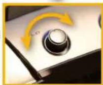
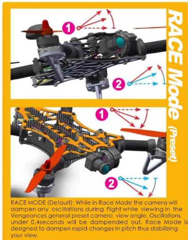
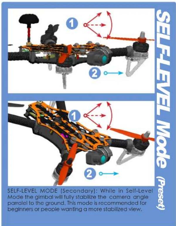
There are two types of gimbal stabilization modes. First mode (by default) is "Race Mode". The second mode is "Self-Level Mode". To change between modes quickly press the "Mode Change Button" twice with a small tool.
DO NOTE: Mode switching cannot be remembered by the gimbal after unplugging the battery. When you unplug the battery from the Vengeance the gimbal will reset to "Race Mode" by default.
PPM Receiver and Gimbal Note: While using RACE MODE adjusting the camera angle via PPM is not supported. SELF-LEVEL MODE is not supported via PPM wire. If you wish to have full-access to your camera gimbal you must use a standard PWM receiver.
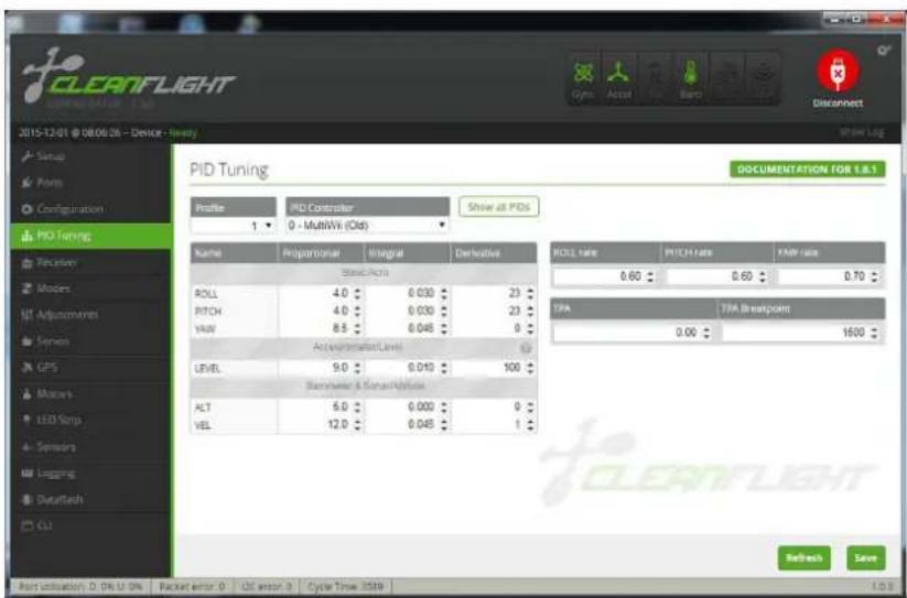
PID Tuning Configuration. PID Tuning is used to adjust the flight characteristics. Default PID settings for the Vengeance is set for beginners and intermediate pilots. If you wish to fly faster you may reduce the ROLL and PITCH PID settings both by -0.2 for reduced sensitivity.
If you wish to increase the sensitivity of the Vengeance's ROLL / PITCH/ YAW you may increase the PID settings to no more than 0.8,
otherwise it will be difficult to control. DO NOTE! You must "Save and Reboot" to save changes onto your flight controller.
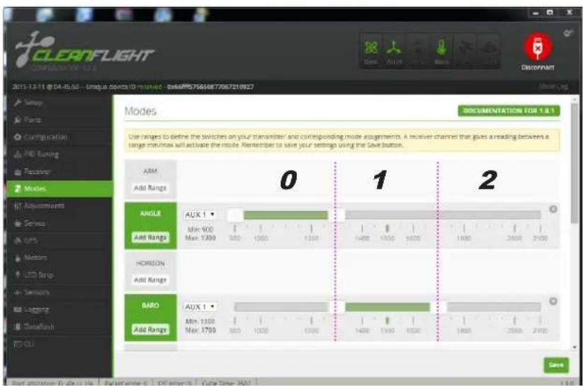
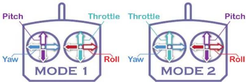
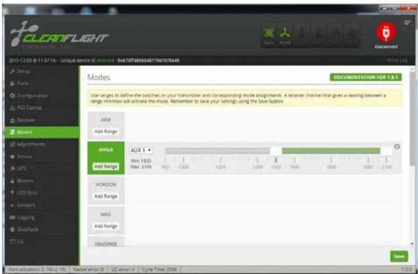
The Vengeance includes three preset flight modes. The fight mode switch is used on Ch.5 of your transmitter, a three-position toggle switch is recommended.
0: ANGLE: For beginners use. Features automatic level stabilization. *Due to the eight degree forward motor-tilt the Vengeance will naturally try to fly slightly forward while hovering.
1: ANGLE + BARO: For beginners use. Features automatic level stabilization. Integrated BMP sensor will automatically will try to hold the flight altitude.
2: Manual: For advance use. Disables automatic level stabilization. Used for rolls and flips.
DO NOTE! You must "Save and Reboot" to save changes onto your flight controller.
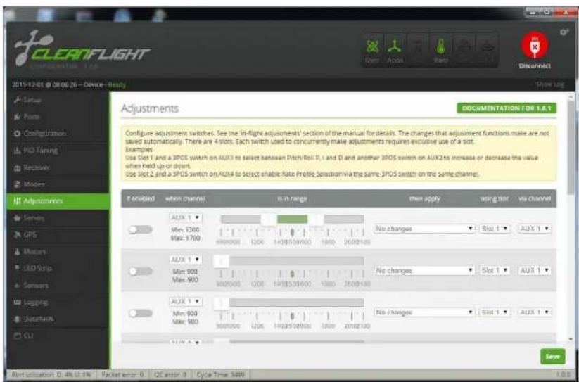
"Adjustments" Configuration Page: Here is where you can set advanced features on the Vengeance via AUX channels on your Transmitter.
It is important to understand all the functions that you enable. Check your AUX channel's by looking at the "Channel Map" configuration page.
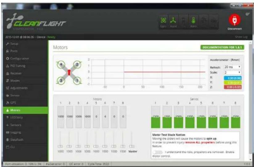
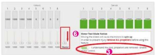
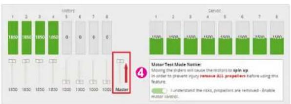
Motor Configuration Page: This page is used to adjust your motor settings if you wish to do so, though the Vengeance becomes already pre-configured. Before testing this feature make sure to remove ALL propellers before trying. Failure to do so may result in bodily harm.
How to configure your ESC adjustments:
The Vengeance uses four different motors and ESC's. Sometime there might be a inconsistent distribution of power among your Vengeance which could lead to poor flight performance and handling. To reset your ESC and tune them properly please follow the below steps:
- Remove ALL propellers before configuration! Failure to do so may lead to bodily harm.
- Connect the Flight Controller to CleanFlight without the main flight battery connected.
- Turn the motor "Test Switch On"
- Move the "Master" switch to the maximum level
- Connect the main flight battery to the Vengeance. Wait five seconds after the ESC makes a gradual rise in noise
- Move the "Master" switch to the minimum level, you will hear a gradual decline in ESC sound.
- Turn OFF the Master Switch and unplug the flight battery.
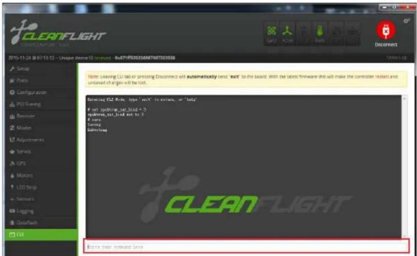
10.How to bind Spektr um satellite r eceiver?
![CLEANFLIGHT COMPLORATOR 1.1.1 2015-11-24 @ 07/08/12 - Unique (Voice ID) device - BoxE7F93032566670672636M Setup Form Configuration PID Tuning Receiver Methods Adjustments Services GPS Motors LED Snap Sensors Logging Dataflash CU Yam Adjustment (Jug) Receiver Mode RX_PFM RPM RX Input RX_SERIAL Serialized receiver GPEKSAT, SRUS, ( SUMD) RX_PARALLEL_PMM PWM RX Input RX_MSP MSP RX Input Serial Receiver Provider Note: Remember to configure a Serial Port (via Ports port) and choose a Serial Receiver Provider when using RX_SERIAL Feature GPEKTRUMIDR GPEKTRUMIDR MOSIP SUMD Receiver Failcale Battery Voltage VBAT Battery voltage monitoring Minimum Cell voltage 4.3 Maximum Cell voltage Warning Cell voltage 110 Voltage Scale Current Sensor CURRENT_METER Battery current monitoring 400 Scale the output voltage to milliseconds [1/1 inch min/Hz] Offset in milliost steps Enable support for legacy Matlab MSP current output](/content/2026/05/1032879/images/91d9593ffbca2b8abbea8180ce6d4e6012c8998e8e5ac0b74d92b63a7385c682.jpg)
- Go to the "Ports" page. Under the UART2 page area activate the "Serial RX" tab. (Press Save and Reboot)
- Go to the "Configuration" page. Select the "RX_Serial" option and whether you are using Spektrum 1024 or 2048 compatible receivers. (Press Save and Reboot)
- Go to the "Receiver" page. Select the Channel Map for JR/ Spektrum/Graupner radios. (Press Save and Reboot)
- Enter into the command line the following code:
"Set spektrum_sat_ = X" "Enter"
X Value = Receiver mode
3 = DSM2 1024bit / 22ms
5 = DSM2 2048bit / 11ms
7 = DSMX 1024bit / 22ms
9 = DSMX 2048bit / 11ms
- Insert "Save" and press Enter. A Message pop-up will appear "Save & Rebooting."
- Unplug the USB, then immediately reconnect USB.
- The satellite receiver LED will start to flash.
- Hold the "Bind" switch on your transmitter and turn ON.
- The Satellite receiver LED will dim and then reappear. You are now binded.
11. Configuring your VTX.
The Vengeance utilizes a 5.8GHz Selectable 25mW / 250mW Video Transmitter with 40Ch's with Raceband.
Changing Channels and Bands:
Push button for more than 2 Seconds: Change Band.
Push button for less than 1 Second: Change Frequency Channel.
The Vengeance's VTX utilizes a 25mW and 250mW selectable VTX. In most European and Western Countries 25mW is the maximum Rf output for 5.8Ghz. Please check with your law and regulations to make sure that you confirm with the law.
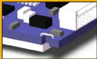
Adjusting the Rf power output for increased range. You may cut the "RF limit wire" so that you may transmit at 200mW power. If you wish to later transmit at 25mW you may solder the "RF limit wire" again.
| Hyperion FXT 5.BGHz 40 Channel AV Transmitter | ||||||
| Modulate Wideband FM Modulate | ||||||
| Video Format NTSC / PAL | ||||||
| Characteristics | Value Units | |||||
| Min. Typ. Max. | ||||||
| 1 | Output Impedance --- 50 --- Ohm | |||||
| 2 | Output Power | FX795T-L/ 25mW | 12 | 13 | 14 | dBm |
| FX795T-2/200mW | 22 | 23 | 24 | dBm | ||
| 3 | Frequency Range | 5645-5945 | Mhz | |||
| 4 | Operating Voltage | 7.0 | 12 | 20 | V | |
| 5 | Supply current | FX795T-L/ 25mW | - | 70 | - | mA |
| FX795T-2/200mW | - | 200 | - | mA | ||
| 6 | Output Voltage(VOUT) | VOUT=5V V | ||||
| 7 | Operating Temperature | -10°C -- +85°C | ||||
| 8 | Video Band Width | 0 | --- | 8.0 | Mhz | |
| 9 | Audio Carrier Frequency | --- | 6.5 | --- | Mhz | |
| 10 | Video Input Level | 0.8 | 1.0 | 1.2 | Vp-p | |
| 11 | Video Input Impedance | --- 75 | --- Ohm | |||
| 12 | Audio Input Level 0.5 --- | 2.0 | Vp-p | |||
| 13 | Audio Input Impedance | 10K | Ohm | |||
| 14 | Weight | --- | 7.5 | --- | Gram(s) | |
| 15 | Antenna Connector | SMA Female Connector | ||||
| 16 | Dimensions (L x W) | 31x22mm | ||||
Change RF Output?
natural_image
3D rendered diagram of a microchip or circuit board with blue and white components (no text or symbols visible)When the "mode change wire" is not cut the VTX will transmit in 25mw. (Default)
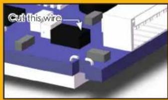
↑ To output in 250mw power you must cut the "rf limit wire".
Channel button
Long press : Change Group
Short press : Change Channel
25mW/250mW Change
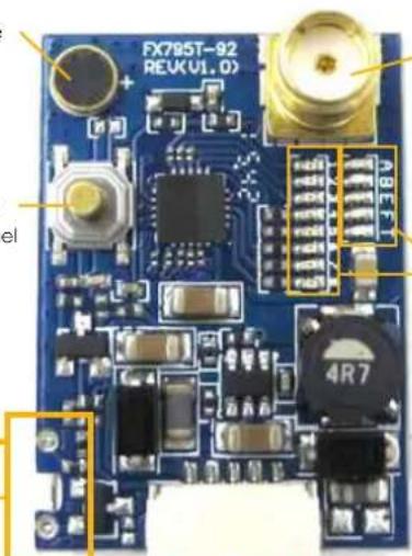
Antenna Connection Jack:
NOTE: Do not power ON your Vengeance without the VTX Antenna installed.
Group LED Channel LED

DC7\~24V in GND Video in GND DC5V out
Vengeance 5.8Ghz Channel
| Group/ Channel | Channel 1 | Channel 2 | Channel 3 | Channel 4 | Channel 5 | Channel 6 | Channel 7 | Channel 8 |
| Group1 (A) 57 | 740 5760 5780 | 5800 5820 5840 | 5860 5880 | |||||
| Group2 (B) 57 | 705 5685 5665 | 5645 5885 5905 | 5925 5945 | |||||
| Group3 (C) 58 | 65 5845 5825 | 5805 5785 5765 | 5745 5725 | |||||
| Group4 (D) 56 | 58 5695 5732 | 5769 5806 5843 | 5880 5917 | |||||
| Group5 (E) 57 | 33 5752 5771 | 5790 5809 5828 | 5847 5866 |